Embed Size (px)
Citation preview

CMPE 257 Winter'11 1
CMPE 257: Wireless and Mobile Networking
Katia Obraczka Computer Engineering
UCSC Baskin Engineering Lecture 5

CMPE 257 Winter'11 2
Announcements • Project proposals. • Student presentations.
– 10 students so we need 5 lectures. • 2 students per lecture.
– Topics: • Security. • Mobility management. • Hybrid networks. • Energy management. • DTNs

CMPE 257 Winter'11 3
Today
• Finish MAC. • Unicast routing.

IEEE 802.11
• Provides 2 types of medium access: – DCF: distributed coordination function. – PCF: point coordination function.
• DCF is contention-based. • PCF is polling-based.
– Collision free. – Implemented atop DCF.
CMPE 257 Winter'11 4
DCF PCF

IEEE 802.11 DCF
• Physical carrier sensing: – Stations listen to channel before
transmitting (CS of CSMA/CA). • Virtual carrier sensing:
– CA OF CSMA/CA. – “Reserve” channel for transmission. – Use RTS/CTS handshake.
CMPE 257 Winter'11 5

CMPE 257 Winter'11 6
IEEE 802.11 MAC Protocol: CSMA (no CA)
802.11 sender 1 if sense channel idle for DIFS then
transmit entire frame (no CD) 2 if sense channel busy then
start random backoff time timer counts down while channel idle transmit when timer expires if no ACK, increase random backoff interval,
repeat 2
802.11 receiver - if frame received OK return ACK after SIFS (ACK needed due to
hidden terminal problem)
sender receiver
DIFS
data
SIFS
ACK

IEEE 802.11 MAC Protocol: CSMA/CA
• Physical CS + virtual CS. – Sense channel for DIFS.
• RTS/CTS handshake before sending data.
• RTS is 20 bytes and CTS is 16 bytes. • Maximum data frame is 2,346 bytes.
CMPE 257 Winter'11 7
Note: This is only for unicast transmissions. Broadcast Transmissions do not use virtual carrier sensing.

CSMA-CA Examples
CMPE 257 Winter'11 8
A
C D B
E
Scenario: A wants to transmit to C. . A sends RTS. . D defers. . C sends CTS. . B defers.
F

CMPE 257 Winter'11 9
IEEE 802.11 Wireless LAN • 802.11b
– 2.4-5 GHz unlicensed spectrum – up to 11 Mbps – direct sequence spread
spectrum (DSSS) in physical layer
• all hosts use same chipping code
• 802.11a – 5-6 GHz range – up to 54 Mbps
• 802.11g – 2.4-5 GHz range – up to 54 Mbps
• 802.11n: multiple antennae – 2.4-5 GHz range – up to 200 Mbps
• All use CSMA/CA for multiple access. • All have base-station and ad-hoc network
modes.
CMPE 257 Winter'11 10
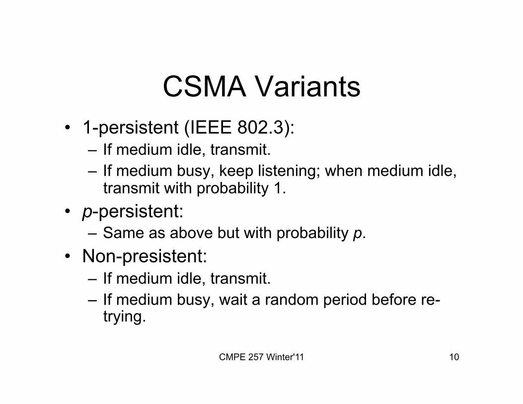
CSMA Variants • 1-persistent (IEEE 802.3):
– If medium idle, transmit. – If medium busy, keep listening; when medium idle,
transmit with probability 1. • p-persistent:
– Same as above but with probability p. • Non-presistent:
– If medium idle, transmit. – If medium busy, wait a random period before re-
trying.

CMPE 257 Winter'11 11
MAC: A Bird’s Eye View

CMPE 257 Winter'11 12
Solutions to Hidden/Exposed Nodes in CSMA
• Use only virtual CS: – RTS/CTS (Request-To-Send/Clear-To-Send) – Used by MACA (Multiple Access Control
Avoidance) and MACAW (MACA for Wireless LANs).
• Use both physical- and virtual CS: – CSMA/CA, IEEE 802.11.

CMPE 257 Winter'11 13
Dynamic Reservation Approaches: Sender- vs. Receiver-initiated
• Sender-initiated: – A node wanting to send data takes the initiative of
setting up the reservation. – Most existing schemes.
• Receiver-initiated: – A receiving node polls a potential transmitting node
for data. – A node can send data after being polled. – E.g., MACA-By Invitation.
CMPE 257 Winter'11 14
Single vs. Multiple Channel Protocols
• Single channel protocols: control and data use the same channel.
• Multiple channel protocols: separate channels for control & data transmission; data transmission on separate channels.

CMPE 257 Winter'11 15
Other criteria for classification
• Power-aware. – E.g., PAMAS.
• Directional or omnidirectional antennas. • QoS-aware
– End-to-end (E2E) delay – Packet loss rate (or the probability) – Available bandwidth – Challenges: lack of centralized control, limited bandwidth, node
mobility, power/computational constraints, error-prone nature of wireless media.
CMPE 257 Winter'11 16
MACAW
• [Bharghavan, 1994]. • Proposed as improvement to MACA
[Karn, 1990]. • Note that first IEEE 802.11 standard
(IEEE 802.11 “legacy”) released in 1997.

CMPE 257 Winter'11 17
MACA
• Proposed as alternative to CSMA. • Introduced CA.
– RTS/CTS handshake (2-way).

CMPE 257 Winter'11 18
MACA • If node A wants to transmit to B, it first sends an RTS
packet to B, indicating the length of the data transmission to follow.
• B returns a CTS packet to A with the expected length of the transmission.
• A starts transmission when it successfully receives CTS. – RTS and CTS packets are much shorter than data packets.
• A neighboring node overhearing an RTS defers its own transmission until the corresponding CTS would have been finished.
• A node hearing the CTS defers for the expected length of the data transmission.

CMPE 257 Winter'11 19
MACA (Cont’d)
• Nodes close to sender: – If no CTS heard, OK to transmit. – Avoid exposed terminal problem: nodes that hear
only RTS can transmit simultaneously with RTS sender.
• Nodes close to receiver: – Upon hearing CTS, defer till after data. – Avoid hidden terminal.
• Binary exponential backoff (BEB). – Possible unfair channel allocation (starvation).
CMPE 257 Winter'11 20
MACAW
• Inspired 802.11. • 2 basic changes to MACA:
– Additional signaling. – Modified backoff algorithm.

CMPE 257 Winter'11 21
MACAW Backoff • Tries to avoid BEB’s unfairness. • Proposed fix: sharing congestion information
among nodes. – Backoff counter information propagated in packet
header. – After successful transmission, neighbors have the
same backoff counter. • Tries to prevent large variations of the back-
off value. – Multiplicative increase (1.5), linear decrease
(decremented by 1).

CMPE 257 Winter'11 22
Data Transmission in MACAW
• Added ACK. – Reliability at layer 2. – If ACK not received:
• Retransmit frame. • Increment backoff timer.

CMPE 257 Winter'11 23
Data Transmission in MACAW • Added small “Data Sending” (DS) control frame.
– Addresses exposed terminal problem. • In MACA, exposed node (received RTS but not CTS) is allowed to
transmit. – Example: S1->R1 and S2->R2
• CTS from R2 may collide with transmission S1->R1. • S2 backs-off.
– Fix: make sure S2 knows RTS-CTS exchange between S1 and R1 was successful.
• S1 sends small control frame, DS with data exchange duration. • When S2 receives DS, defers its transmission.
R1 S1 S2 R2

CMPE 257 Winter'11 24
Data Transmission in MACAW • Added “Request for Request-to-Send” (RRTS). • R2 contends on behalf of S2 if it received RTS from S2 when it
could not have responded because deferring due to S1->R1 exchange.
• When S2 receives RRTS from R2, proceeds with RTS, etc.
S2 R2 R1 S1 RRTS RRTS

CMPE 257 Winter'11 25
FAMA Protocols • Floor Acquisition Multiple Access.
– Floor acquisition = gain control of channel. • MACA is an example of a FAMA
protocol. – Floor acquisition on packet-by-packet
basis. – No physical CS; only virtual CS. – For collision freedom, RTS needs to be at
least 2*channel-propagation-delay. • .

FAMA Paper (Garcia-Luna et al.)
• FAMA non-persistent packet sensing, or FAMA-NPS. – No carrier sensing, i.e., MACA. – Uses ALOHA to transmit RTS.
CMPE 257 Winter'11 26

CMPE 257 Winter'11 27
FAMA-NTR • FAMA non-persistent transmit request. • Sender can send packet bursts. • Combines non-persistent CS + RTS/
CTS exchange. • Enforces waiting periods at sender and
receiver. • For both data and control frames. • Waiting period proportional to maximum
propagation time.

CMPE 257 Winter'11 28
FAMA-NTR (cont’d)
• Before sending: – Node senses
channel. – If channel busy,
backs-off for random period and retries later => non-persistent.
– If channel free, node sends RTS.
• Node waits CTS for 1 RTT. – If CTS not received,
node backs-off. – Otherwise, transmits
data burst (up to a maximum size).

CMPE 257 Winter'11 29
FAMA-NTR
• To allow bursts, receiving station waits after processing each data packet. – Waiting period (T) = maximum propagation time.
• Transmitting node waits for 2T after any control frame. – Allows enough time for RTS-CTS exchange.

CMPE 257 Winter'11 30
Unicast Routing in MANETs

CMPE 257 Winter'11 31
Why MANET routing is challenging?
• No fixed infrastructure. – Nodes can have unlimited mobility. – So?
• Multiple hops to destination. • Unreliable communication medium. • All nodes need to participate in routing/
forwarding. – Also, security issues.

CMPE 257 Winter'11 32
Mobility
• Mobility patterns may vary widely. – Stationary nodes (e.g., sensor nodes). – Highly mobile nodes (e.g., vehicles). – Discrete versus continuous mobility. – Structured versus unstructured mobility.
• Mobility characteristics: – Speed. – Direction. – Pause time.
CMPE 257 Winter'11 33
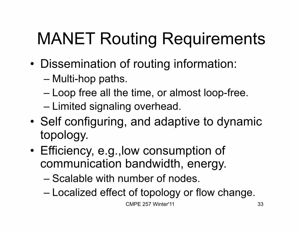
MANET Routing Requirements • Dissemination of routing information:
– Multi-hop paths. – Loop free all the time, or almost loop-free. – Limited signaling overhead.
• Self configuring, and adaptive to dynamic topology.
• Efficiency, e.g.,low consumption of communication bandwidth, energy. – Scalable with number of nodes. – Localized effect of topology or flow change.
CMPE 257 Winter'11 34
MANET Unicast Routing • Many protocols have been proposed. • Many have been invented specifically
for MANETs. • Many are adapted from protocols for
wired networks. • Can any one protocol work well in all
MANET environments?

CMPE 257 Winter'11 35
DV or LS?

CMPE 257 Winter'11 36
DV or LS? • Distance-Vector Algorithm: Routers
exchange their distances to known destinations; a router uses the distance vectors received from its neighbors to compute its own distances. Distributed computation is problem.
• Link-State Algorithm: Routers exchange information about the state of the links in the network; a router uses this information to compute its distances to destinations. Distributed database problem.

CMPE 257 Winter'11 37
Proactive or Reactive?

CMPE 257 Winter'11 38
MANET Unicast Routing Taxonomy
• Proactive protocols: – A.k.a, table-driven. – Traditional routing protocols are proactive. – Compute and maintain routes independent on
traffic demand/patterns. – E.g., OLSR.
• Reactive protocols: – Compute and maintain routes “on-demand”. – E.g., DSR, AODV.
• Hybrid protocols. – E.g., ZRP.

CMPE 257 Winter'11 39
Tradeoffs?
• Latency of route discovery. – Proactive protocols may have lower latency
since routes are maintained at all times. – Reactive protocols may have higher
latency because a route from X to Y will be found only when X attempts to send to Y.

CMPE 257 Winter'11 40
Tradeoffs?
• Overhead of route discovery/maintenance. – Reactive protocols may have lower overhead
because routes are determined only if needed. – Proactive protocols may result in higher overhead
due to continuous route updating (depends on rate of changes).
• Which approach achieves better trade-offs depends on the traffic and mobility patterns.

CMPE 257 Winter'11 41
What about Flooding?

CMPE 257 Winter'11 42
Flooding for Data Delivery
• Sender broadcasts data packet “P” to all its neighbors.
• Each node receiving “P” forwards it to its neighbors.
• Sequence numbers used to avoid forwarding P more than once. Why?
• P reaches destination if reachable from source. Destination does not forward P.

CMPE 257 Winter'11 43
Flooding

CMPE 257 Winter'11 44
Flooding

CMPE 257 Winter'11 45
Flooding
• Advantages: – Simplicity. – Efficient when rate of
information transmission lower than topology changes.
– Robustness.
• Disadvantages: – High overhead. – May result in network
congetion.

CMPE 257 Winter'11 46
Flooding for the Control Plane
• Many protocols perform flooding of control packets. – E.g., route discovery and maintenance.
• Overhead of control packet flooding may be amortized over data packets transmitted.

CMPE 257 Winter'11 47
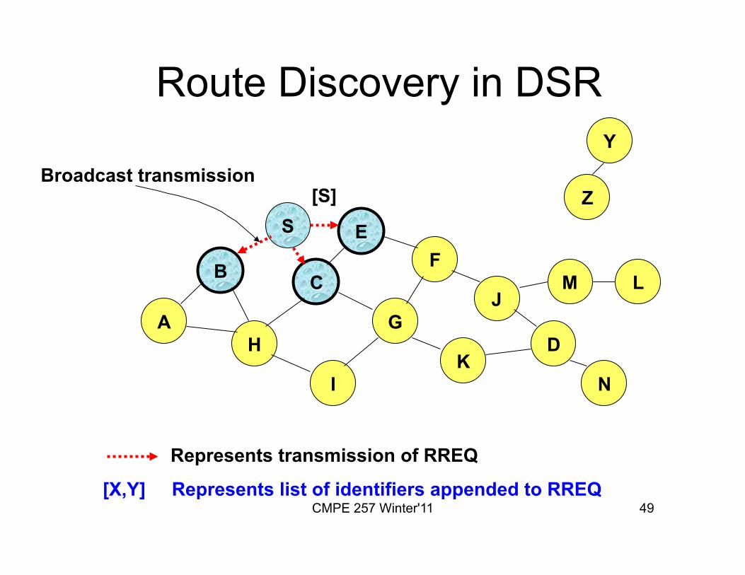
Dynamic Source Routing (DSR) [Johnson96]
• Reactive protocol. • When node S wants to send a packet to
D, and does not have a route to D, node S initiates a route discovery.
• S floods Route Request (RREQ). • Each node appends own identifier when
forwarding RREQ.

CMPE 257 Winter'11 48
Route Discovery in DSR
B
A
S E F
H
J
D
C
G
I K
Z
Y
Represents a node that has received RREQ for D from S
M
N
L
CMPE 257 Winter'11 49
B
A
S E F
H
J
D
C
G
I K
Represents transmission of RREQ
Z
Y
Broadcast transmission
M
N
L
[S]
[X,Y] Represents list of identifiers appended to RREQ
Route Discovery in DSR

CMPE 257 Winter'11 50
B
A
S E F
H
J
D
C
G
I K
• Node H receives packet RREQ from two neighbors: potential for collision
Z
Y
M
N
L
[S,E]
[S,C]
Route Discovery in DSR

CMPE 257 Winter'11 51
B
A
S E F
H
J
D
C
G
I K
• Node C receives RREQ from G and H, but does not forward it again, because node C has already forwarded RREQ once
Z
Y
M
N
L
[S,C,G]
[S,E,F]
Route Discovery in DSR

CMPE 257 Winter'11 52
B
A
S E F
H
J
D
C
G
I K
Z
Y
M
• Nodes J and K both broadcast RREQ to node D • Since nodes J and K are hidden from each other, their transmissions may collide
N
L
[S,C,G,K]
[S,E,F,J]
Route Discovery in DSR

CMPE 257 Winter'11 53
B
A
S E F
H
J
D
C
G
I K
Z
Y
• Node D does not forward RREQ, because node D is the intended target of the route discovery
M
N
L
[S,E,F,J,M]
Route Discovery in DSR

CMPE 257 Winter'11 54
• Destination D on receiving the first RREQ, sends a Route Reply (RREP).
• RREP is sent on a route obtained by reversing the route appended to the received RREQ.
• RREP includes the route from S to D on which RREQ was received by node D.
Route Discovery in DSR

CMPE 257 Winter'11 55
Route Reply in DSR
B
A
S E F
H
J
D
C
G
I K
Z
Y
M
N
L
RREP [S,E,F,J,D]
Represents RREP control message

CMPE 257 Winter'11 56
Route Reply in DSR • RREP can be sent by reversing the route
in RREQ only if links are guaranteed to be bi-directional
• If unidirectional (asymmetric) links are allowed, then RREP may need a route discovery for S from D. – Unless D already knows a route to S. – If a route discovery is initiated by D for a route
to S, then the RREP is piggybacked on D’s RREQ.
CMPE 257 Winter'11 57
Processing RREP
• Node S on receiving RREP, caches the route. • When node S sends a data packet to D, the
entire route is included in the packet header – Hence the name source routing.
• Intermediate nodes use the source route included in a packet to determine to whom a packet should be forwarded.

CMPE 257 Winter'11 58
Data Delivery in DSR
B
A
S E F
H
J
D
C
G
I K
Z
Y
M
N
L
DATA [S,E,F,J,D]
Packet header size grows with route length

CMPE 257 Winter'11 59
DSR Optimization: Route Caching
• Each node caches a new route it learns by any means. – When node S finds route [S,E,F,J,D] to node D, node S also
learns route [S,E,F] to node F. – When node K receives Route Request [S,C,G], K learns
route [K,G,C,S] to S. – When node F forwards Route Reply RREP [S,E,F,J,D], F
learns route [F,J,D] to D. – When node E forwards Data [S,E,F,J,D] it learns route
[E,F,J,D] to node D – Nodes may also learn route when it overhears data.

CMPE 257 Winter'11 60
Use of Route Caching • When S learns that a route to D is broken, it
uses another route from its local cache, if such a route to D exists in its cache; otherwise, S initiates route discovery.
• Node X on receiving a RREQ for some node D can send a RREP if X knows a route to D.
• Use of route cache – Can speed up route discovery. – Can reduce propagation of route requests.

CMPE 257 Winter'11 61
Use of Route Caching
A
E
D G
[P,Q,R]: Represents cached route at a node
M
N
L
[S,E,F,J,D] [E,F,J,D]
[C,S]
[G,C,S]
[F,J,D],[F,E,S]
[J,F,E,S]
Z
K H
B
S
F C
I
J

CMPE 257 Winter'11 62
Route Caching: Speed up Route Discovery,
Reduce RREQ Flooding
A
E
J
D K
M
N
L
[S,E,F,J,D] [E,F,J,D]
[C,S] [G,C,S]
[F,J,D],[F,E,S]
[J,F,E,S]
RREQ When node Z sends a route request for node C, node K sends back a route reply [Z,K,G,C] to node Z using a locally cached route
[K,G,C,S] RREP
Route caches at K and J limit the flooding of Z’s RREQ.
Z
H
B C
S
F
I
G

CMPE 257 Winter'11 63
Route Error (RERR)
B
A
S E F
H
J
D
C
G
I K
Z
Y
M
N
L
RERR [J-D]
J sends a route error to S along route J-F-E-S when its attempt to forward the data packet S (with route SEFJD) on J-D fails. Nodes hearing RERR update their route cache to remove link J-D

CMPE 257 Winter'11 64
Route Caching: Beware! • Stale caches can adversely affect
performance. – With time and host mobility, cached routes
may become invalid. – A sender host may try several stale routes
(obtained from local cache, or replied from cache by other nodes), before finding a good route.

CMPE 257 Winter'11 65
DSR: Advantages • Routes maintained only between nodes who
need to communicate. – Reduces overhead of route maintenance.
• Route caching can further reduce route discovery overhead.
• Single route discovery may yield many routes to the destination, due to intermediate nodes replying from local caches.

CMPE 257 Winter'11 66
DSR: Disadvantages • Packet header size grows with route
length. • Flood of route requests may potentially
reach all nodes in the network. – Care must be taken to avoid collisions
between route requests propagated by neighboring nodes. • Insertion of random delays before forwarding
RREQ.

CMPE 257 Winter'11 67
DSR: Disadvantages • Increased contention if too many route
replies come back due to nodes replying using their local cache. – “RREP” storm problem. – Reply storm may be eased by preventing a
node from sending RREP if it hears another RREP with a shorter route.

CMPE 257 Winter'11 68
DSR: Disadvantages • An intermediate node may send RREP
using a stale cached route, thus polluting other caches. – This problem can be eased if some
mechanism to purge (potentially) invalid cached routes is incorporated. • Static timeouts. • Adaptive timeouts based on link stability.

CMPE 257 Winter'11 69
AODV • Route Requests (RREQ) are forwarded
similarly to DSR. – When a node re-broadcasts a RREQ, it sets up a
reverse path pointing towards the source. – AODV assumes symmetric (bi-directional) links.
• When the intended destination receives a RREQ, it replies by sending a RREP.
• RREPs travel along the reverse path set-up when RREQ is forwarded.

CMPE 257 Winter'11 70
Route Requests in AODV
B
A
S E F
H
J
D
C
G
I K
Z
Y
Represents a node that has received RREQ for D from S
M
N
L

CMPE 257 Winter'11 71
Route Requests in AODV
B
A
S E F
H
J
D
C
G
I K
Represents transmission of RREQ
Z
Y
Broadcast transmission
M
N
L

CMPE 257 Winter'11 72
B
A
S E F
H
J
D
C
G
I K
Represents links on Reverse Path
Z
Y
M
N
L
Route Requests in AODV

CMPE 257 Winter'11 73
AODV Route Discovery: Observations
• RREQ contains source and destination IP address, current destination seq. number (incremented as a result of loss of prior route), and broadcast id (incremented for every RREQ). – Source IP + bcast id uniquely identifies RREQ: nodes do not
forward RREQs they have forwarded recently. – RREQ processing: node creates reverse route table entry for
RREQ source with TTL. – If node has “unexpired” route to destination in its table with
sequence number >= RREQ’s, it replies to RREQ with Route Reply (RREP) back to source.
– Otherwise, broadcast RREQ onward.

CMPE 257 Winter'11 74
Destination Sequence Number
• When node D receives route request with destination sequence number N, D sets its sequence number to N, unless it is already larger than N.
• Node’s own sequence number is monotonically increasing. – Sequence number is incremented after
neighborhood topology change.

CMPE 257 Winter'11 75
Reverse Path Setup in AODV
B
A
S E
D G
I K
• Node C receives RREQ from G and H, but does not forward it again, because node C has already forwarded RREQ once
Z
Y
M
N
L
H
C F
J

CMPE 257 Winter'11 76
Reverse Path Setup in AODV
B
A
S E F
H
J
D
C
G
I K
Z
Y
M
N
L

CMPE 257 Winter'11 77
Reverse Path Setup in AODV
B
A
S E F
H
J
D
C
G
I K
Z
Y
• Node D does not forward RREQ, because node D is the intended target of the RREQ
M
N
L

CMPE 257 Winter'11 78
Route Reply in AODV • An intermediate node has current route to destination,
responds to RREQ with RREP. • RREP contains source and destination IP, current
sequence number, number of hops to destination. – If destination, then destination seq. #. – Else, node’s current record of destination’s seq. #.
• Node receiving RREP sets up forward path to destination.
• If multiple RREPs received, node forwards first one. Later RREPs discarded unless greater seq. # or smaller # of hops.

CMPE 257 Winter'11 79
Route Reply Example
B
A
S E F
H
J
D
C
G
I K
Z
Y
Represents links on path taken by RREP
M
N
L

CMPE 257 Winter'11 80
Forward Path Setup in AODV
B
A
S E F
H
J
D
C
G
I K
Z
Y
M
N
L
Forward links are setup when RREP travels along the reverse path
Represents a link on the forward path

CMPE 257 Winter'11 81
Data Delivery in AODV
B
A
S E F
H
J
D
C
G
I K
Z
Y
M
N
L
Routing table entries used to forward data packet. Route is not included in packet header.
DATA

CMPE 257 Winter'11 82
Timeouts • A routing table entry maintaining a reverse path is
purged after a timeout interval. – Timeout should be long enough to allow RREP to come
back.
• Routing table entry maintaining a forward path is purged if not used for active_route_timeout interval. – If no data being sent using a particular routing table entry,
that entry will be deleted from the routing table (even if the route may actually still be valid).

CMPE 257 Winter'11 83
Link Failure Reporting • Link failures are propagated by means of Route Error
messages, which also update destination sequence numbers. – RERR lists destinations now unreachable.
• If upstream node has neighbors as precursors for the affected destinations, it broadcasts RERR.
• Nodes receiving the RERR update cost to destination to infinity and forward RERR if needed.
• Upon receiving RERR, source will initiate route discovery if still needs route.

CMPE 257 Winter'11 84
Route Error • When node X is unable to forward packet P (from
node S to node D) on link (X,Y), it generates a RERR message.
• Node X increments the destination sequence number for D cached at node X.
• The incremented sequence number N is included in the RERR.
• When node S receives the RERR, it initiates a new route discovery for D using destination sequence number at least as large as N.

CMPE 257 Winter'11 85
Link Failure Detection • Hello messages: neighbor nodes
periodically exchange hello messages. • Absence of hello message is used as
an indication of link failure. • Alternatively, failure to receive several
MAC-level ACKs may be used as an indication of link failure.

CMPE 257 Winter'11 86
AODV Packet Header
• RREQ: – RREQ id. – Destination IP
address. – Destination
sequence number. – Originator IP
address. – Originator sequence
number.
• RREQ id + originator IP uniquely identifies the RREQ.
• Originator sequence number.
• Destination sequence number.

CMPE 257 Winter'11 87
Destination Sequence Number
• Avoid using stale routes. • Node updates its destination seq. # when:
– It generates a RREQ. • Prevents conflicts previously established reverse routes.
– It generates a RREP. • New-seq-# = max(current seq #, RREQ dest. seq #).

CMPE 257 Winter'11 88
Sequence Numbers in AODV
• To prevent formation of loops
– Assume that A does not know about failure of link C-D because RERR sent by C is lost
– Now C performs a route discovery for D. A receives the RREQ (say, via path C-E-A)
– A will reply since it knows a route to D via B. – Results in a loop (for instance, C-E-A-B-C )
A B C D
E
A B C D
E

CMPE 257 Winter'11 89
Optimization: Expanding Ring Search
• RREQs are initially sent with small Time-to-Live (TTL) field, to limit their propagation. – DSR also includes a similar optimization.
• If no RREP is received, then larger TTL tried.

CMPE 257 Winter'11 90
Does The Sequence Numbering Work?
• To some extent: – Sequence numbering scheme is not very
efficient. – Scheme requires that any given node A
either never forgets a destination sequence number it learns, or is able to wait “long enough” so that it cannot possibly attempt to reach a destination D through a path involving a node B that uses A to reach D.

CMPE 257 Winter'11 91
Summary: AODV
• Routes not included in packet header. • Nodes maintain routing table entries for
“active” routes. • At most one route (next hop) maintained
at each node. • Unused routes expire even if topology
does not change.

CMPE 257 Winter'11 92
Optimized Link State Routing (OLSR) [RFC 3626]
• Overhead of flooding link state information reduced by having fewer nodes forward the information.
• Broadcast from X only forwarded by its multipoint relays (MPRs).
• Overhead is also reduced as the size of the LS updates is reduced: LS updates contain only info on MPRs.

CMPE 257 Winter'11 93
OLSR • OLSR floods information through MPRs. • Flooded information contains links connecting
nodes to respective MPRs. – I.e., node sends info on nodes that selected it as
their MPR. – Periodic HELLO messages inform nodes which
other nodes selected it as their MPR. • Routes used by OLSR only include multipoint
relays as intermediate nodes.

CMPE 257 Winter'11 94
MPRs • Multipoint relays of node X are its
neighbors such that each two-hop neighbor of X is a one-hop neighbor of at least one multipoint relay of X. – Each node transmits its neighbor list in
periodic beacons, so that all nodes know their 2-hop neighbors.
• MPRs of X are 1-hop neighbors of X covering X’s 2-hop neighbors.

CMPE 257 Winter'11 95
Optimized Link State Routing (OLSR)
• C and E are multipoint relays of A.
A
B F
C
D
E H
G K
J
Node that has broadcast state information from A

CMPE 257 Winter'11 96
Optimized Link State Routing (OLSR)
• Nodes C and E forward information received from A.
A
B F
C
D
E H
G K
J
Node that has broadcast state information from A

CMPE 257 Winter'11 97
Optimized Link State Routing (OLSR)
• E and K are multipoint relays for H. • K forwards information received from H.
– E has already forwarded the same information once.
A
B F
C
D
E H
G K
J
Node that has broadcast state information from A
L


