Embed Size (px)
DESCRIPTION
corrosion
Citation preview

Corrosion

Corrosion: a chemical or between a material and its
environment that produces a deterioration of the material and its properties
electrochemical reaction
Corrosion
Electrochemical reaction: chemical reactions in which elements are added or removed
from a chemical species and at least one of the species undergoes a change in the
number of valance electrons
Electrochemical Corrosion:
Wet (aqueous) - systems that corrode at low T with a liquid electrolyte
2
Wet (aqueous) - systems that corrode at low T with a liquid electrolyte
Dry (oxidation) - corrosion that occurs at high T (generally over 500˚C)
Aqueous:
Uniform or General
Galvanic or Two-metal
Crevice
Pitting
Intergranular
Velocity-assisted
Environment-assisted cracking
Oxidation:
High Temperature
No moisture nor dissolved electrolytes
Low Temperature
surfaces where T< 135°C
condensation of the acidic sulphur and
chlorine-containing gases
Liquid Metal Embrittlement:
- The dissolution-diffusion model
adsorption of the liquid metal on the solid metal induces dissolution and inward
diffusion
under stress these processes lead to crack nucleation and propagation
- brittle fracture theory
adsorption of the liquid metal atoms at the crack tip weakens inter-atomic bonds and
propagates the crack
Chemical Corrosion
propagates the crack
- diffusion penetration
penetration of liquid metal atoms to nucleate cracks which under stress
- ductile failure model
adsorption of the liquid metal leads to weakening of atomic bonds and nucleation of
dislocations which move under stress, pile-up and work harden the solid.
dissolution helps in the nucleation of voids which grow under stress and cause ductile
failure
Examples: Hg and aluminum alloys, Bi and copper alloys 3

Electrochemical Corrosion - Oxidation
Low Temperature
surfaces where T< 135°C
condensation
acidic sulfur
chlorine-containing gases
High Temperature:
no moisture nor dissolved electrolytes
e.g. direct reaction with oxygen
Y2O3 Y2O3-X
Fe Fe O
4
2 3 2 3-X
Fe Fe2O3

Oxidation – Ellingham Diagram
Low Temperature
surfaces where T< 135°C
condensation
acidic sulfur
chlorine-containing gases
High Temperature:
no moisture nor dissolved electrolytes
e.g. direct reaction with oxygen
Y2O3 Y2O3-X
Fe Fe O
5
2 3 2 3-X
Fe Fe2O3
4Fe + 3O2 2Fe2O3
∆G = ∆G0 + RT ln k
K = [C]c [D]d
[A]a [B]b
K= Po
Used for oxidation and reduction of ore
2

Galvanic Corrosion
Zn(s) Zn2+ + 2e-
Cu2+ + 2e- Cu(s)
Anodic
Cathodic
Zn (s) + Cu2+ Zn2+ + Cu (s)
Daniell Cell
Galvanic Cell
Two half cells
Half cell
charge balance
metal
solution of metal salt
One cell oxidizes the other
direction depends on driving force
6
An+ + ne- A
Bm+ + me- B
mA + nBm+ nB + mAn+
General Reaction

Standard Hydrogen EMF Test – 25°C
Metal sample mass increases
(gold is the cathode, +)
- +
0
Metal sample mass decreases
(iron is the anode, -)
- +
0
Used to develop EMF Series
Two outcomes:
Ag2+
(1M Ag2+) (1M H+)
H+
H+
H+
H+
Pla
tin
um
e-
e-
Go
ld
e-e-
Ag2+
Ag2+
Fe2+
(1M Fe2+) (1M H+)
H+
H+
H+
H+ H2
Pla
tin
um
e-
e-
Iro
n
e-
e-
Fe2+
Fe2+
Vmetal < 0 (relative to Pt) Vmetal > 0 (relative to Pt)
7

• EMF series • Metal with smaller
V corrodes.• Ex: Cd-Ni cell
metalo
- +
more cathodic Au
Cu
Pb
Sn
Ni
Co
+1.420 V
+0.340
- 0.126
- 0.136
- 0.250
- 0.277
metal Vmetalo
∆V = o
Standard EMF Series
Ni
1.0 M
Ni2+ solution
1.0 M
Cd2+ solution
Cd 25°C
more anodic
more cathodic
Co
Cd
Fe
Cr
Zn
Al
Mg
Na
K
- 0.277
- 0.403
- 0.440
- 0.744
- 0.763
- 1.662
- 2.262
- 2.714
- 2.924
0.153V
Data based on Table 17.1, Callister 6e.
8

Aqueous Types
Standard Calomel Electrode (SCE):
antiquated
contains mercury!
reaction between:
Hg
Hg2Cl2 (calomel)
aqueous phase: saturated KCl in H2O
referenced as 0V
9
referenced as 0V
redox potential is +0.2444 V vs. SHE at 25 °C
Standard Hydrogen Electrode (SHE):
modern method

Aqueous Types
Galvanic Corrosion:
Two metals in contact act similar to a model corrosion cell
electrically conduction path
driving force (EMF)
electrolyte (aqueous solution, air)
10
©2003 Brooks/Cole, a division of Thomson Learning, Inc. Thomson Learning™ is a trademark used herein under license.

Aqueous Types
Galvanic Corrosion:
Can be detrimental, or beneficial, the difference is up to the engineer!
11
Stainless steel bolts in zinc plated steel. Zinc anodes on painted LAS.
in both cases, the zinc is less noble. It’s use determines the success of the system

Aqueous Types
Uniform Corrosion:
most common corrosion type
corrosion rate is often expressed as a distance per year
usually mils (1 mil = .001 inches = .0254 mm)
Mils penetration per year (MPY) = 534 x W / (ρAt)
W = weight loss in milligrams
ρ = density (g/cm3)
12
ρ = density (g/cm3)
A = area (in2)
t = time (hrs)
< 1 MPY is outstanding, 5-20 good, 50-200 poor

Simple Aqueous Corrosion (uniform)
Fe Fe2+ + 2e-
O2 + 4e- + 2H2O 4OH-
2Fe2+ + 4OH- 2Fe(OH)2
Fe Fe2+ + 2e-
2H+ + 2e- H2
Anodic
Cathodic
Anodic
Cathodic
Aerobic (Dissolved Oxygen)
Fe2+ + 2Cl- FeCl2(aq)
Anaerobic
Require four components: anode, cathode, conduction path (contact), and electrolyte
2Fe(OH)3 Fe2O3 + 3H2O
2Fe3+ + 6OH- 2Fe(OH)3
Fe Fe3+ + 3e-
O2 + 6e- + 3H2O 6OH-
13
Rust
O2 O2
Fe
Fe2+OH- OH-
e- e-
Fe
e- e-
H+Fe2+H+ H+H+H+H+
H2H2
H+Cl-
H+Cl-
(active corrosion) (partially passivates)
2Fe(OH)3 Fe2O3 + 3H2O

Controlling Uniform Corrosion
Uniform Corrosion:
The earliest attempts at slowing corrosion involved additions of copper to steel
Still used today
High Strength Low Alloy Steel
not made to specific chemical composition
specific mechanical properties.
carbon content between 0.05–0.25%
14
carbon content between 0.05–0.25%
retain formability and weldability
<2.0% Mn
Cu, Ni, Nb, N, V, Cr, Mo, Ti, Ca, Zr, or rare earth elements (Y, Hf)
Cu, Ti, V, and Nb are added for strengthening purposes
Cu, Si, Ni, Cr, P increase corrosion resistance
Zr, Ca, and RE’s control inclusion shape
Control-rolled, pearlite-reduced, microalloyed, acicular ferrite, dual-phase, and Weathering
Controlling Uniform Corrosion
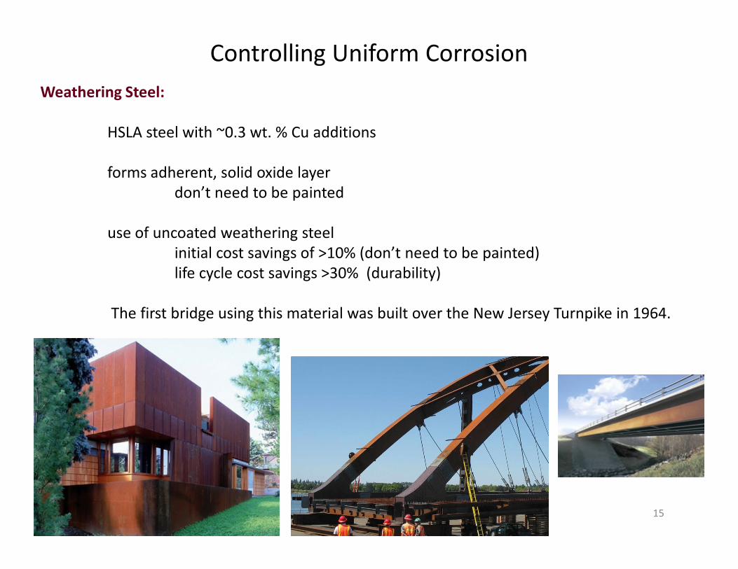
Weathering Steel:
HSLA steel with ~0.3 wt. % Cu additions
forms adherent, solid oxide layer
don’t need to be painted
use of uncoated weathering steel
initial cost savings of >10% (don’t need to be painted)
life cycle cost savings >30% (durability)
15
The first bridge using this material was built over the New Jersey Turnpike in 1964.

Simple Aqueous Corrosion (uniform)
Fe Fe2+ + 2e-
O2 + 4e- + 2H2O 4OH-
2Fe2+ + 4OH- 2Fe(OH)2
Fe Fe2+ + 2e-
2H+ + 2e- H2
Anodic
Cathodic
Anodic
Cathodic
Aerobic (Dissolved Oxygen)
Fe2+ + 2Cl- FeCl2(aq)
Anaerobic
Require four components: anode, cathode, conduction path (contact), and electrolyte
2Fe(OH)3 Fe2O3 + 3H2O
2Fe3+ + 6OH- 2Fe(OH)3
Fe Fe3+ + 3e-
O2 + 6e- + 3H2O 6OH-
16
Rust
O2 O2
Fe
Fe2+OH- OH-
e- e-
Fe
e- e-
H+Fe2+H+ H+H+H+H+
H2H2
H+Cl-
H+Cl-
(active corrosion) (partially passivates)
2Fe(OH)3 Fe2O3 + 3H2O

Stainless Steels
What is stainless steel?
- an iron alloy containing >12% chromium
Applications
- endless applications
chemical handling, marine applications, aesthetics
- one purpose: corrosion resistance
17
Petrochemical nuclear architecture consumer

“Stain-less” Steel
- each SS type has its weakness
Austenitics
- pH value < 1.0
Introduction
“Stainless” Steel
- “rustless”, “stainless”, “inox (inoxydable)”
- originally a miracle material
- chlorides
acidic chlorides (MgCl2 and BaCl2)
seawater
- galvanic
self, more noble alloys
Sensitization
- improper heat treatment
intergranular corrosion
18
New York Times: Jan 31, 1915 New York Times: Jan 22, 1922

How do Stainless Steels Work? Passivation
Fe Fe2+ + 2e-
O2 + 4e- + 2H2O 4OH-
2Fe2+ + 4OH- 2Fe(OH)2
Anodic
Cathodic
Aerobic (Dissolved Oxygen)
Oxidation
Begins with Cr and Fe oxidation
forms passivating layer
very rapid (ms)
HCP Cr2O3 layer
kinetic inhibitor
tenacious
allows cold work, welding, etc
19
(fully passivates)
Fe-Cr(OH)2-3
O2 O2
Fe2+
OH-OH-
e- e-
Cr-rich
base metal
Cr2O3
Fe-Cr

Transpassive Corrosion
Fe Fe2+ + 2e-
2H+ + 2e- H2
Anodic
Cathodic
Fe2+ + 2Cl- FeCl2(aq)
Low pH Corrosion
Breakdown
increased potential (e.g. very low pH)
attacks passivating layer
accelerated in pitted area
pitting
20
Fe-Cr(OH)2-3
Fe2+
e- e-
(partially passivates)
Fe-Cr
Cr-rich
base metal
Cr2O3
H+ H+ H+
H2H2
Fe2+
Cr2+

Crevice Corrosion
1) Oxygen is consumed in crevice by slow passive corrosion
2) Passive corrosion continues, and pH falls by Cr3+ hydrolysis
O2 + 4e- + 2H2O 4OH- (Cathodic)
Cr Cr3+ + 3e- (Anodic)
Cr3+ + 3H2O Cr(OH)3 + H+
H+ + Cl- HCl(aq)
localized decrease in pH (<2)
3) Passive film breaks down in acid and rapid active corrosion starts
4) Active corrosion causes even stronger acidification and stabilizes the crevice corrosion
Breakdown of the Passivating Layer
4) Active corrosion causes even stronger acidification and stabilizes the crevice corrosion
21
e-
OH-
O2
Cl-
M+H+

Breakdown
Surface Roughness
Local environment
pH
Film disruption
chloride ions
Underlying microstructure
Breakdown of the Passivating Layer
Steel
Cl- Cl-
Cl-
γ α’
H+H+H+
Flow
Electrolyte
Underlying microstructure
inclusions
slip bands
surface roughness
phase interfaces
grain boundaries
Stress gradients
22
Steel
©2003 Brooks/Cole, a division of Thomson Learning, Inc. Thomson
Learning™ is a trademark used herein under license.

Chromium Additions to Steel
- Beginning in 18201
- added to medium steel (0.10-0.30% C)
improved hardenability
- 1913, stainless steel “invented”
Harry Brearley
Brown Firth Laboratories
Fe-12.8% Cr-0.24% C
(martensitic)
Carbide Formation
Fe-Cr Phase Diagram (Calphad)Fe-Cr-0.1C Phase DiagramCarbide Formation
23
Fe-Cr Phase Diagram (Calphad)Fe-Cr-0.1C Phase DiagramCarbide Formation
- too brittle for practical use
- solubility limit (<0.02%C)
- Cr23C6 precipitates
1000hr
400°C
600°C
800°C
1000°C
0.1 hr 1 hr 10 hr 100 hr
Cr23C6
Air cool

Chromium Additions - Carbide
Temper-Brittleness
brittle carbide on grain boundary
limitation with early Fe-Cr alloys
Carbon Content
Lower C, less propensity to carbide formation
move the nose
“stainless iron” c. 1920
24
Aitchison, L. Engineering Steels: An exposition of the properties…. D. Van Nostrand Company. New York. 1921.
1000hr
400°C
600°C
800°C
1000°C
0.1 hr 1 hr 10 hr 100 hr
Air cool
Quench
Cr23C6
0.30%0.15%0.05%
Sourmail, T. Stainless Steel. University of Cambridge. 2010.

Nickel and Chromium Additions
Fe-Ni
Austenite stabilizer
demotes martensite formation
tough, solid solution
1889 – first nickel additions (for strength)1
Austenitic Stainless Steel
25
Austenitic Stainless Steel
1914 – austenitic stainless steel invented
<1% C, <20% Ni and 15-40% Cr
Friedrich Krupp AG
Eduard Maurer and Benno Strauss
Provide ductility, toughness, workability
Fe-Ni Phase diagram (Calphad)
1Riley

Not so Fast
Austenitic Stainless Steel
- invented in 1914
Friedrich Krupp AG
Eduard Maurer and Benno Strauss
- limited use throughout the war effort
high temperature applications (e.g. valves)
“Krupp Krankheit” (Krupp’s Disease)
“that peculiar property of nickel chromium steels known as temper-brittleness”
26
“that peculiar property of nickel chromium steels known as temper-brittleness”
- intergranular disintegration
without apparent external cause
- decay is always observed from the surface
corrosion process
- only in isolated cases
traced to faulty heat treatment
Aitchison, L. Engineering Steels: An exposition of the properties…. D. Van Nostrand Company. New York. 1921.

Microcell Theory1
local galvanic couple
(Cr-Fe)23C6 cathode (noble)
matrix anode
weakness: self healing, >12% Cr
Stress Theory2
local stresses around carbide
imperfect passivation
weakness: magnitude
Sensitization Corrosion Theories
18Cr-8Ni
(Cr-Fe)23C6
<12Cr
weakness: magnitude
Carbide Corrosion Theory3
carbides preferentially corrode
weakness: noble
Chromium Depletion Theory4,5,6,7
Cr below passivating
generally applicable
27
18%
12%
8%
Cr
1Stickler, 1963 2Lula, 1954 3Shvartz, 1959 4Strauss et al, 1930 5Bain,1933 6Hillert, 1969 7Tedmon, 1971

~70% Cr
Chromium Depletion Theory
18% Cr
12% Cr
0.1% C0.08% C
20nm 0nm 20nm
5.68% C
28
18%
12%
8%
Cr
18% Cr
12% Cr
0.3% C
0.08% C
20nm 0nm 20nm
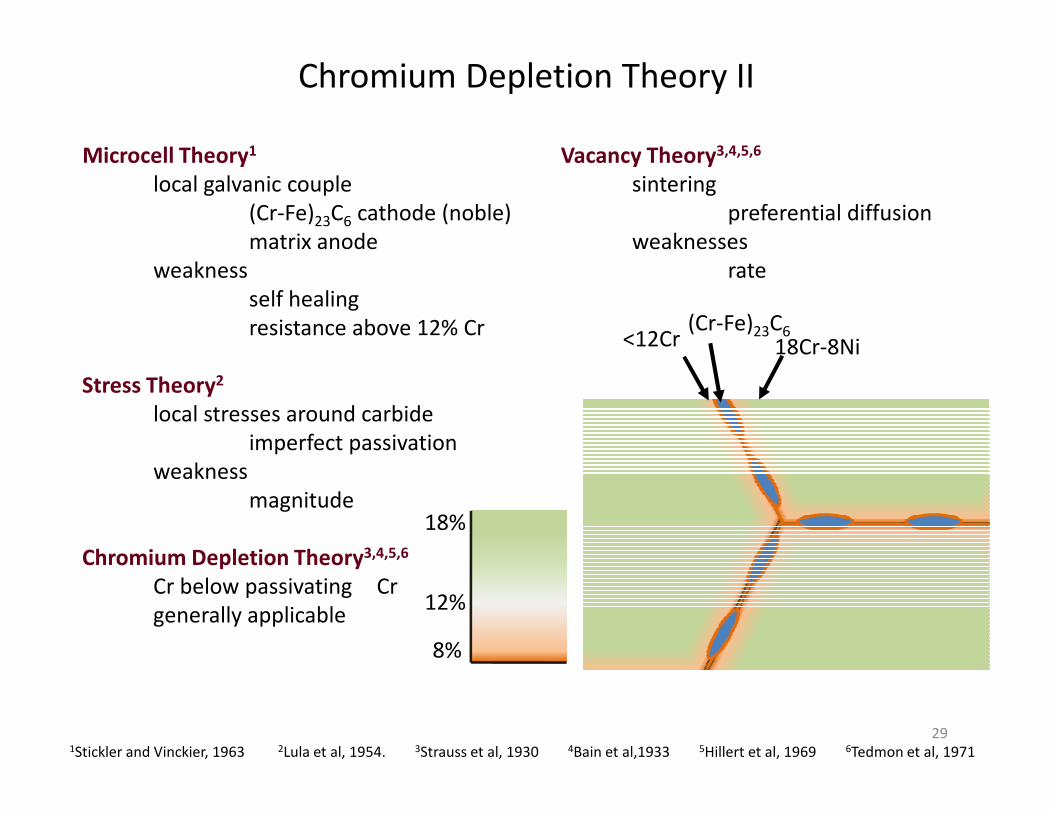
Chromium Depletion Theory II
18Cr-8Ni(Cr-Fe)23C6<12Cr
Microcell Theory1
local galvanic couple
(Cr-Fe)23C6 cathode (noble)
matrix anode
weakness
self healing
resistance above 12% Cr
Stress Theory2
local stresses around carbide
Vacancy Theory3,4,5,6
sintering
preferential diffusion
weaknesses
rate
29
18%
12%
8%
Cr
local stresses around carbide
imperfect passivation
weakness
magnitude
Chromium Depletion Theory3,4,5,6
Cr below passivating
generally applicable
1Stickler and Vinckier, 1963 2Lula et al, 1954. 3Strauss et al, 1930 4Bain et al,1933 5Hillert et al, 1969 6Tedmon et al, 1971

Goal/Hypothesis
Provide explanation for “Krupp Krankheit”
Method
Relate problem to heat treatment
carbide formation
Increasing Carbon Content
0.04% C, 9.30% Ni, 18.3% Cr
0.06% C, 9.22% Ni, 18.0% Cr
strain
UTSσy
1930 – Strauss, Schottky, and Hinnüber
0.06% C, 9.22% Ni, 18.0% Cr
0.12% C, 8.40% Ni, 18.6% Cr
Summary
1) > potential w/> C = carbides
2) > carbide precip at > T, but < corrosion
3) depletion in immediate region, at higher t the C had more time to diffuse
4) > hardness - martensite being formed? (magnetism detected)
5) corrosion still seen in austenitic nickel-containing alloys (no magnetism)
7) 25%Cr, 20% Ni, 0.15% C has only weak tendency to intergranular corrosion
σy
30
Strauss, B., H. Schottky, and J. Hinnüber. Zeitschrift für anorganische und allgemeine Chemie. Vol 188. No. 1. pp 309-324. 1930.

Shvartz and Kristal
C control for sensitization
Cr control for self-healing
Baumel
GB diffusion for sensitization
volume diffusion for self-healing
Strawström and Hillert
sensitization and self-healing
Modeling efforts
sensitization and self-healing
uniform grain boundary film
alloy-carbon-M23C6 local equilibrium
Tedmon, Vermilyea, and Rosolowski
sensitization only
non uniform carbide film
free energy of carbide formation
31
Strawstrom, C., and M. Hillert. An Improved Depleted-Zone Theory of Intergranular Corrosion of 18-8 Stainless Steel. Journal of the Iron and
Steel Institute. Vol 207. pp 77-85. 1969.
20nm 0nm 20nm20nm 0nm 20nm

Analytical Techniques
Early Studies
Corrosion Testing
(Moneypenny-)Strauss Test: H2SO4-CuSO41
Huey Test: boiling HNO3
optical microscopy
showed pits/trenches
low resolution
no chemical informationAitchinson, 1921
32
Models
all proposed before proof of depletion
Strauss, Schottky, and Hinnüber, 1930
Bain , Aborn and Rutherford,1933
Strawström and Hillert, 1969
Tedmon, Vermilyea, and Rosolowski, 1971
1Strauss et al, 1930 2Mahl, 1940 2Schaefer and Harker, 1942
Bain, 1933

First Confirmation
Joshi and Stein, 1972
Auger electron spectroscopy
fracture surfaces
sulfur, silicon, nitrogen, and phosphorus at GB
confirmed Cr-depletion
Subsequent Study
AES1,2
Atom Probe13
Proof of Chromium Depletion
Atom Probe13
STEM/EDS3,4,5,6,7,8,9,10,11,12
increasing resolution
1977 >50nm
1983-1984 50nm
1983-1986 25nm
1989 5nm
Model Validation
main chromium depletion effect
33
Hopkinson, B.E. and K.G. Carroll. Metallurgy: Chromium Distribution around Grain BoundaryHall, 1984 – 50nm probe sizeOrtner, 1989 – 5nm probe size