Embed Size (px)
Citation preview

Lecture Objectives:
• Finish with thermal storage systems
• Learn about plumbing systems

Construction and benefits Active
Passive (wall)

Modeling(stratified tank)
Write energy and mass balancer equation for each section

Installation of thermal storage system
DownstreamUpstream
• Increases chiller efficiency • Increases chiller capacity • Overall system efficiency ??? • Decreases storage capacity• Simplifies system layout• …..
• Decreases chiller efficiency• Decreases chiller capacityOverall system efficiency ???• Increases storage capacity•……• Does not allow chiller shut down!

Plumbing Systems - Hydronic Terms
• Head loss
• Open-loop vs. closed loop
• Open System
• Closed System
Pump
h
Cooling coil in AHUChiller
Pump

Is this open or closed system ?
Cooling towers
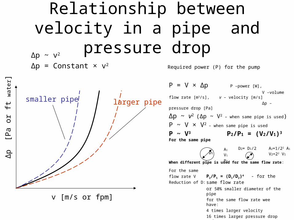
Relationship between velocity in a pipe and pressure drop
Δp ~ v2
Δp = Constant × v2
Δp
[Pa
or
ft w
ater
]
v [m/s or fpm]
larger pipesmaller pipe
Required power (P) for the pump
P = V × Δp P –power [W],
V –volume flow rate [m3/s], v – velocity [m/s]
Δp – pressure drop [Pa]
Δp ~ v2 (Δp ~ V2 – when same pipe is used)
P ~ V × V2 – when same pipe is used
P ~ V3 P2/P1 = (V2/V1)3 For the same pipe
When different pipe is used for the same flow rate:
For the same
flow rate V
Reduction of D:
D1
D2= D1/2 A1
V1
P1
A2=1/22 A1
V2=22 V1
P2/P1 = (D1/D2)4 - for the same flow rate
or 50% smaller diameter of the pipe
for the same flow rate wee have:
4 times larger velocity
16 times larger pressure drop and
16 times lager power for the pump

Head Loss

Fittings
g
Vkh
2
2

Pumps• Raise pressure and produce flow
• Main type• Centrifugal
Inline Base mounted
Example of Turbine pump
Reading (textbook)Page 3-36 - 3-45

Pump curves
• NPSHR = Net Positive Suction Head Required

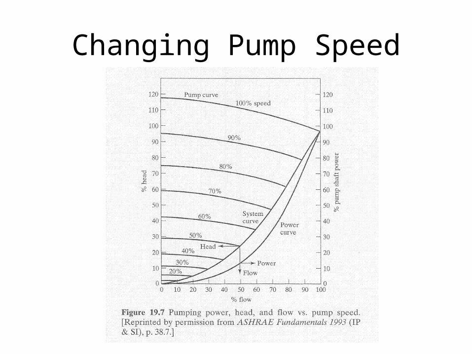
Changing Pump Speed

Net Positive Suction Head(cavitation)

Curve for Multiple Pumps

System Curves
A B∆p
V
A+B
ParallelA B
A B
∆p
V
A+B
A
B
Serial

Find a system curve for this plumbing configuration

Primary/Secondary and Tertiary Pumping (schematics A&B below)
Taylor, S., P. Dupont, B. Jones, T. Hartman and M. Hydeman. 2000. Chilled water plant design guide. San Francisco: Pacific Gas & Electric Company.
http://www.taylor-engineering.com/downloads/cooltools/EDR_DesignGuidelines_CoolToolsChilledWater.pdf
Reading Assignment:

System balancing
BOILER
HC2
AHU1 AHU2
HC1
pump
100 ft 1000 ft
2 gpm 10 gpm
10 ft

Valves• Section 5-14 and 6-15 in the textbook
• Types• Butterfly Valves
• Ball Valves
• Globe Valves
Three way valves

Valve Sizing and Flow Coefficient
Cv value:
in liter/hour or….
in Pa
Control Valve Selection For Hydronic Systems reference:http://www.google.com/url?sa=t&rct=j&q=&esrc=s&source=web&cd=1&cad=rja&uact=8&ved=0CCUQFjAA&url=http%3A%2F%2Fbookstore.ashrae.biz%2Fjournal%2Fdownload.php%3Ffile%3Dhegberg.pdf&ei=IvcqU_O1KMuE2AWgloHgDA&usg=AFQjCNFRAMzPnbzDpAluhyk4l8u_SKKTdw

Control Valve Selection For Hydronic Systems
Before DC we tried to do this
Valve authority