Embed Size (px)
Citation preview

7/23/2019 Lecture Note 1 (Steel)
http://slidepdf.com/reader/full/lecture-note-1-steel 1/30
Materials and Structures
CVEN2302
Lecturer-1: General Principles
Dr Hamid Valipour
7/23/2019 Lecture Note 1 (Steel)
http://slidepdf.com/reader/full/lecture-note-1-steel 2/30
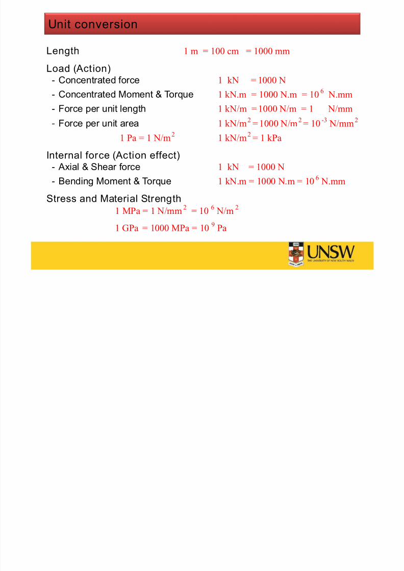
Unit conversion
Length 1 m = 100 cm = 1000 mm
Load (Action)- Concentrated force 1 kN = 1000 N
- Concentrated Moment & Torque 1 kN.m = 1000 N.m = 10
6
N.mm- Force per unit length 1 kN/m = 1000 N/m = 1 N/mm
- Force per unit area 1 kN/m2
= 1000 N/m2= 10
-3 N/mm
2
1 Pa = 1 N/m2
1 kN/m2
= 1 kPa
Internal force (Action effect)- Axial & Shear force 1 kN = 1000 N
- Bending Moment & Torque 1 kN.m = 1000 N.m = 106 N.mm
Stress and Material Strength1 MPa = 1 N/mm
2= 10
6 N/m
2
1 GPa = 1000 MPa = 109
Pa

7/23/2019 Lecture Note 1 (Steel)
http://slidepdf.com/reader/full/lecture-note-1-steel 3/30
Material properties
• Young modulus: E = 200000 MPa= 200 GPa
• Shear modulus: G= 80000 MPa= 80 GPa
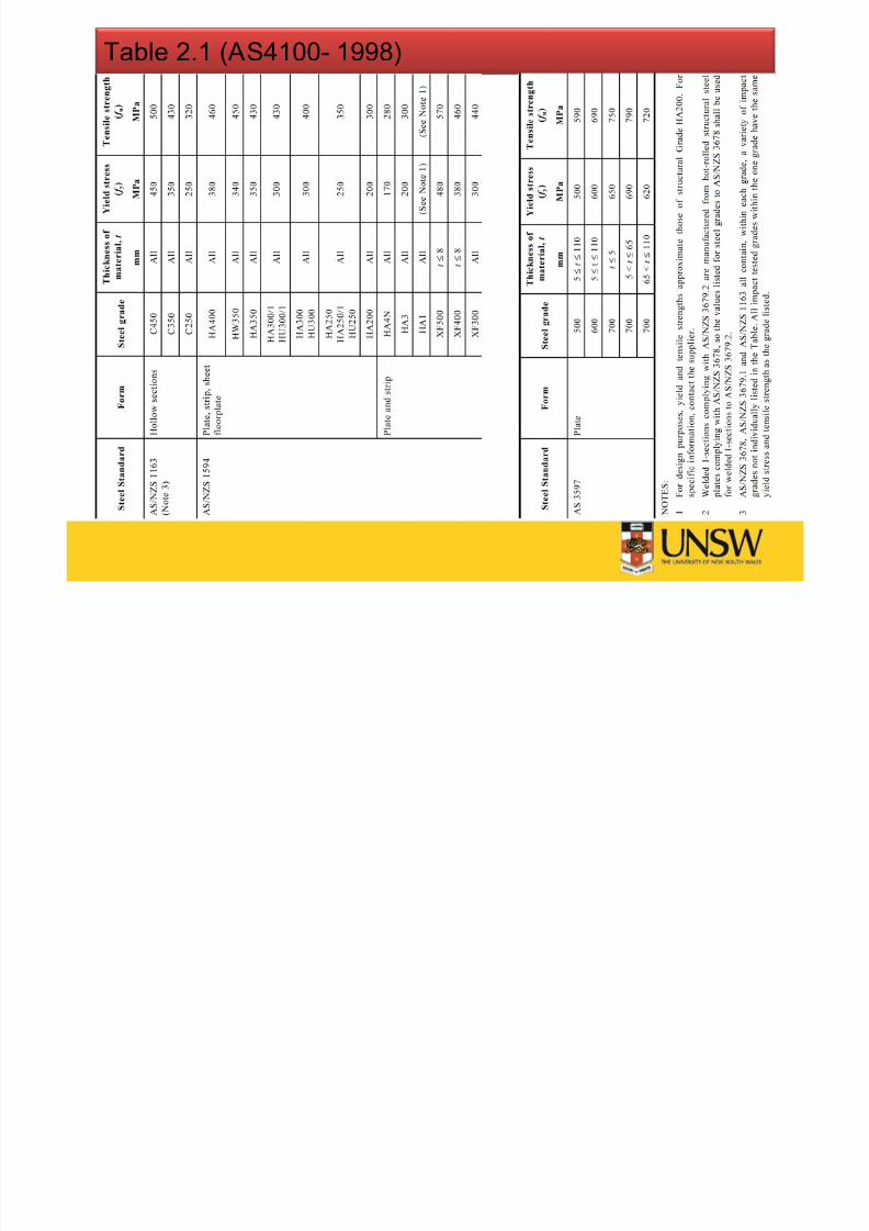
• Yield stress: f y= (MPa)
Shall not exceed that given inTable 2.1 ( AS4100- 1998)
• Ultimate tensile strength: f u= (MPa)
Yield strain:
5102
)MPa(
y y y
f
E
f
y
y u
u f
f yruptureLong plastic
plateau
(Stress)
(Strain)
7/23/2019 Lecture Note 1 (Steel)
http://slidepdf.com/reader/full/lecture-note-1-steel 4/30
Table 2.1 ( AS4100- 1998)
7/23/2019 Lecture Note 1 (Steel)
http://slidepdf.com/reader/full/lecture-note-1-steel 5/30
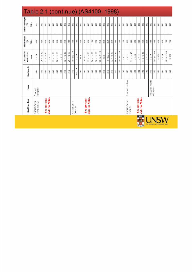
Table 2.1 (continue) ( AS4100- 1998)
S e e p r e v i o u s
s l i d e f o r N o t e s .
S e e p r e v i o u s
s l i d e f o r N o t e s .
S e e p r e v i o u s
s l i d e f o r N o t e s .

7/23/2019 Lecture Note 1 (Steel)
http://slidepdf.com/reader/full/lecture-note-1-steel 6/30
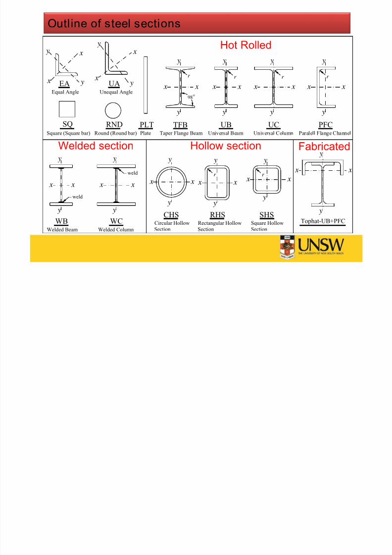
Steel members (Sections)
Classification of sections:
• Hot rolled (plates, taper flange beam, equal leg angle, unequal
leg angle, universal beam, universal column, parallel flange
channel)
• Standard welded sections (welded beam, welded column)
• Cold-formed and welded hollow sections (circular, rectangular
and square hollow sections)
• Fabricated sections (Top hat-UB+PFC)
7/23/2019 Lecture Note 1 (Steel)
http://slidepdf.com/reader/full/lecture-note-1-steel 7/30
Outline of steel sections
x x
y
y
TFB UB
y
y
x x x x
y
y
UC
r
PFC
y
y
x x
98o
EA
x
x
y
y y
y
x
x
UA
WC
y
y
x x x x
y
y
WB
r r r
weld
weld
Universal Beam Universal Column Paralell Flange Channel
Equal Angle Unequal Angle
Welded Beam Welded Column
Taper Flange Beam
Circular HollowSection
CHS RHSRectangular HollowSection
Square HollowSection
SHS
r r
Plate
PLTSQ Square (Square bar) Round (Round bar)
RND
x x
y
y
x x
y
y
x x
y
y
Tophat-UB+PFC
Hot Rolled
Hollow section Fabricated
x
y
x
y
Welded section
7/23/2019 Lecture Note 1 (Steel)
http://slidepdf.com/reader/full/lecture-note-1-steel 8/30
Structure performance
Structures must have reliable performance
under all expected actions such as permanent actions and
imposed actions.
withstand extreme or frequent actions such as wind action and
earthquake action.
Clients have an expectation of satisfactory performance to fulfill
design function under short-term actions such as vibration and foot-fall.
under long-term actions such as element deflections due to creep
in RC structures.
7/23/2019 Lecture Note 1 (Steel)
http://slidepdf.com/reader/full/lecture-note-1-steel 9/30
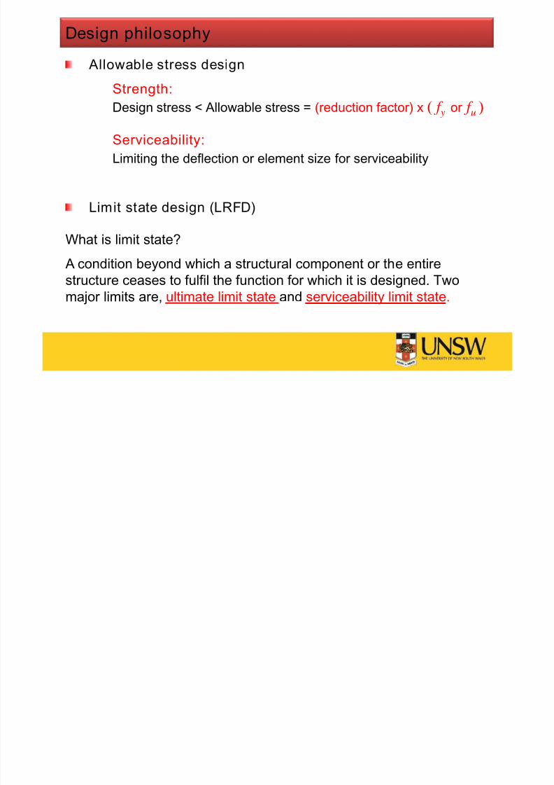
Design philosophy
Allowable stress designStrength:
Design stress < Allowable stress = (reduction factor) x ( f y or f u )
Serviceability:Limiting the deflection or element size for serviceability
Limit state design (LRFD)
What is limit state?
A condition beyond which a structural component or the entire
structure ceases to fulfil the function for which it is designed. Two
major limits are, ultimate limit state and serviceability limit state.

7/23/2019 Lecture Note 1 (Steel)
http://slidepdf.com/reader/full/lecture-note-1-steel 10/30
Design at different levels
StructureMember
Section
Element
Member Structure
Section and Elements
Element
Element Element
Element
Element
Element

7/23/2019 Lecture Note 1 (Steel)
http://slidepdf.com/reader/full/lecture-note-1-steel 11/30
Applicability of AS4100- 1998 (clause 1.1)
This standard sets out minimum requirements for the design, fabrication,erection & modification of steelwork in structures in accordance with the
limit states design concept.
This Standard applies to steel buildings, structures & cranes.
This standard does not apply to:
- Steel elements less than 3 mm thick, with the exception of sections
complying with AS/NZS 1163 and packers.
- Steel members for which the value of the yield stress ( f y ) used indesign exceeds 690 MPa.
- Cold-formed members, other than those complying with AS/NZS 1163,
shall be designed in accordance with AS/NZS 4600.
- Composite steel-concrete members, which shall be designed in
accordance with AS2327.
• Road, railway and pedestrian bridges (AS 5100.1, 2 & 6 apply).

7/23/2019 Lecture Note 1 (Steel)
http://slidepdf.com/reader/full/lecture-note-1-steel 12/30
Definitions
• Action (load): the cause of stress or deformations in a structure
which could be
— dead load or permanent action (G), live load or imposed action (Q),
wind action (W u), earthquake action ( E u), snow (F sn), liquid pressure
(F lp
), rainwater ponding (F pnd
) and ground water (F gw
) in accordance
with (Section 1 AS/NZS 1170[1].0)
• Action effect (load effect): the internal force (i.e. axial force and
shear ) or bending moment due to actions or loads.
• Design action (design load): the combination of the nominal actions
or loads and the load factors as specified in AS1170.
• Design action effect (design load effect): the action or load effectcomputed from the design actions (design loads).
— Axial force ( N * ), Shear force (V * ), Bending moment ( M * ), torsion (T * )
or combination of them
7/23/2019 Lecture Note 1 (Steel)
http://slidepdf.com/reader/full/lecture-note-1-steel 13/30
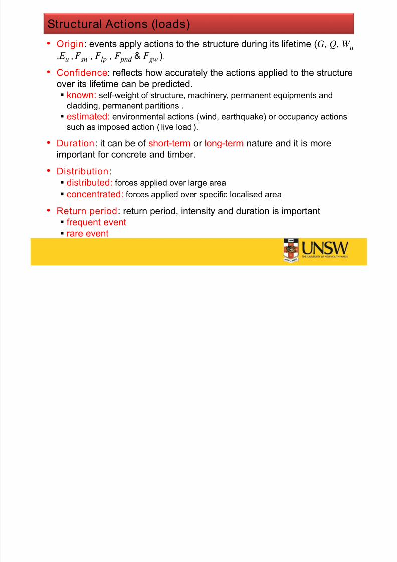
Structural Actions (loads)
• Origin: events apply actions to the structure during its lifetime (G, Q, W u, E u , F sn , F lp , F pnd & F gw ).
• Confidence: reflects how accurately the actions applied to the structure
over its lifetime can be predicted.
known: self-weight of structure, machinery, permanent equipments andcladding, permanent partitions .
estimated: environmental actions (wind, earthquake) or occupancy actions
such as imposed action ( live load ).
• Duration: it can be of short-term or long-term nature and it is moreimportant for concrete and timber.
• Distribution:
distributed: forces applied over large area
concentrated: forces applied over specific localised area
• Return period: return period, intensity and duration is important
frequent event
rare event

7/23/2019 Lecture Note 1 (Steel)
http://slidepdf.com/reader/full/lecture-note-1-steel 14/30
Design process (General)
Project!
Defini tion of project(Design brief)
Includes: specific use,
constraints, functional &
structural requirements
Information search
Includes: design data,
information from other
consultants, loads
Structural systems
(Conceptual design)
Includes:
type of structural system,Connections and
construction techniques
Preliminary designs
and selection
Detailed design
Drawings and technical
specificationsConstruction

7/23/2019 Lecture Note 1 (Steel)
http://slidepdf.com/reader/full/lecture-note-1-steel 15/30
Design process (Structure)
( D e a d &
L i v e L o
a d )
w i n d L o
a d
G,Q
W
Analysis
Load Combination or
Combination of Actions (AS 1170[1].0)
Design action effect
(Design axial force, shear, bending moment)
Design action effect (Capacity factor) (Nominal capacity)
* N M *V *
Idealised model
P e r m a n e
n t & I m p
o s e d L o a d
7/23/2019 Lecture Note 1 (Steel)
http://slidepdf.com/reader/full/lecture-note-1-steel 16/30
General modes of failure
Classification of failure modes
Local
Global
Combination of local and global
Steel yielding (ductile failure mode)
Steel fracture and fatigue (brittle failure mode)
Buckling related failure modes
7/23/2019 Lecture Note 1 (Steel)
http://slidepdf.com/reader/full/lecture-note-1-steel 17/30
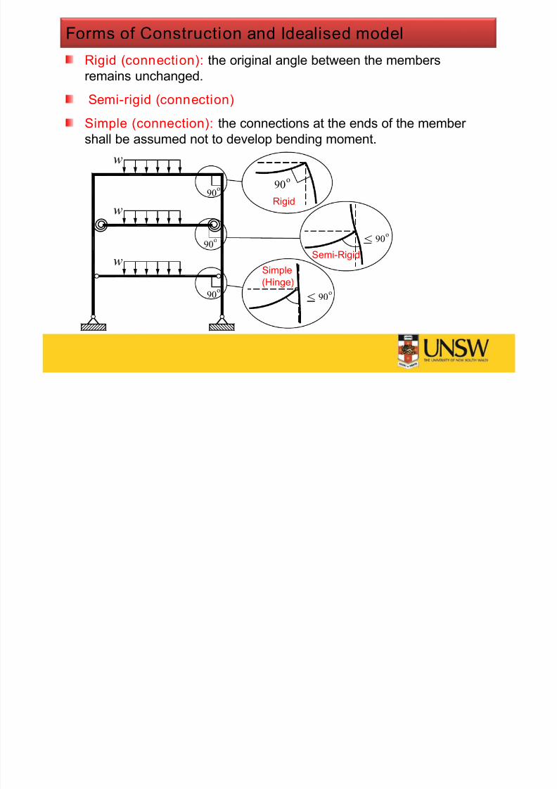
Rigid (connection): the original angle between the members
remains unchanged.
Semi-rigid (connection)
Simple (connection): the connections at the ends of the member
shall be assumed not to develop bending moment.
Forms of Construction and Idealised model
90o
o90
90o
w
90o
90o
<
w
w
< 90o
Rigid
Semi-Rigid
Simple
(Hinge)
7/23/2019 Lecture Note 1 (Steel)
http://slidepdf.com/reader/full/lecture-note-1-steel 18/30
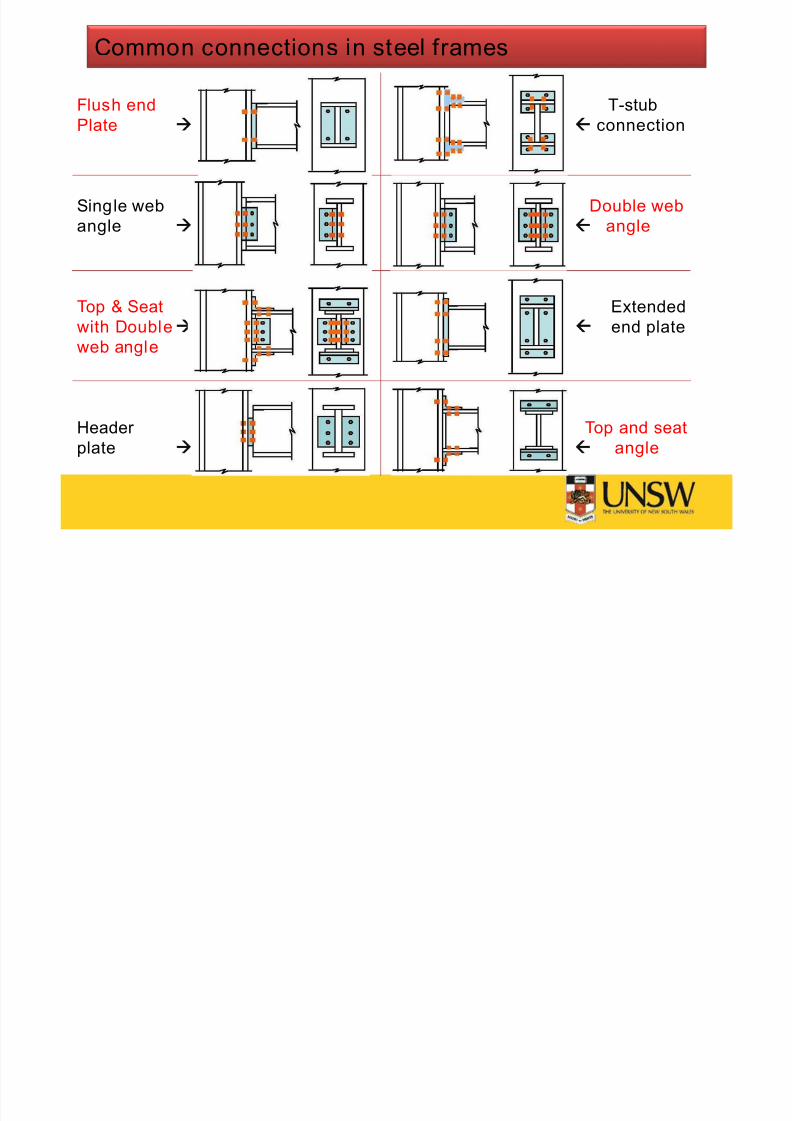
Flush end T-stubPlate connection
Single web Double web
angle angle
Top & Seat Extended
with Double end plate
web angle
Header Top and seat
plate angle
Common connections in steel frames
7/23/2019 Lecture Note 1 (Steel)
http://slidepdf.com/reader/full/lecture-note-1-steel 19/30
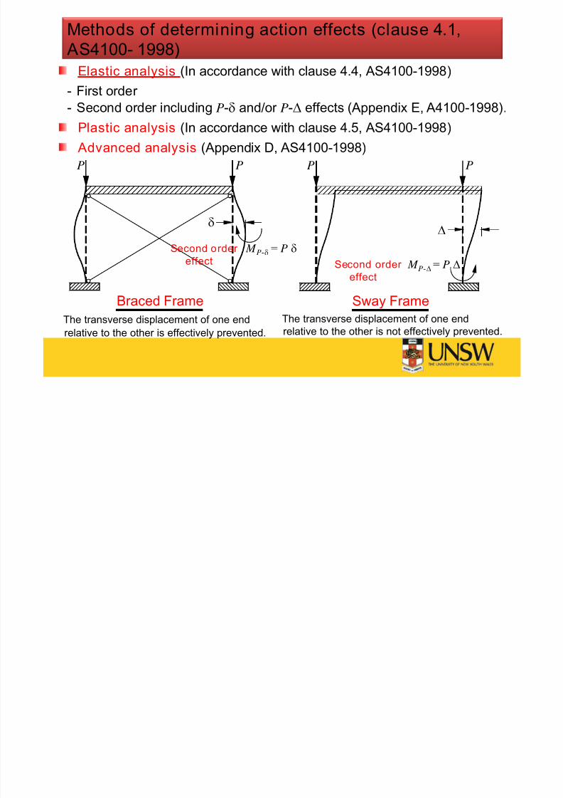
Elastic analysis (In accordance with clause 4.4, AS4100-1998)- First order
- Second order including P- and/or P- effects ( Appendix E, A4100-1998).
Plastic analysis (In accordance with clause 4.5, AS4100-1998)
Advanced analysis ( Appendix D, AS4100-1998)
Methods of determining action effects (clause 4.1,
AS4100- 1998)
P P
Sway Frame
Braced Frame
PP
The transverse displacement of one end
relative to the other is effectively prevented.
The transverse displacement of one end
relative to the other is not effectively prevented.
M = P P-
P- M = P
Second order
effect Second order
effect

7/23/2019 Lecture Note 1 (Steel)
http://slidepdf.com/reader/full/lecture-note-1-steel 20/30
Limit state design
- Stability limit state
The structure as a whole (and any part of it) shall be designed to
prevent instability due to overturning, uplift or sliding
- Strength limit state
The structure and its component members and connections shall bedesigned in such a way that
Design action effect < Design capacity= * Nominal capacity
or S * < Ru
– is capacity reduction factor given in Table 3.4 ( AS4100- 1998).
- Serviceability limit state
The structure and its components shall be designed for the
serviceability limit state by controlling or limiting deflection,vibration, bolt slip and corrosion, as appropriate, in accordance
- Fatigue, Fire, Earthquake and Britt le fracture limit state

7/23/2019 Lecture Note 1 (Steel)
http://slidepdf.com/reader/full/lecture-note-1-steel 21/30
Capacity (reduction) factor
depends on material- steel
- concrete
- timber
and further on
- origin and reliability of strength data
- accuracy of behavioural model
- structural role of member (primary or secondary)
- Effect of failure of a single element on whole structure
7/23/2019 Lecture Note 1 (Steel)
http://slidepdf.com/reader/full/lecture-note-1-steel 22/30
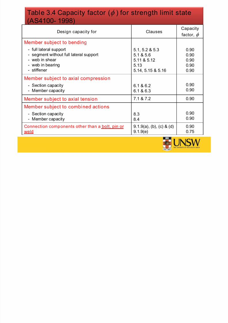
Table 3.4 Capacity factor ( ) for strength limit state
( AS4100- 1998)
Design capacity for Clauses Capacityfactor,
Member subject to bending
- full lateral support
- segment without full lateral support
- web in shear
- web in bearing
- stiffener
5.1, 5.2 & 5.3
5.1 & 5.6
5.11 & 5.12
5.13
5.14, 5.15 & 5.16
0.90
0.90
0.90
0.90
0.90
Member subject to axial compression
- Section capacity- Member capacity
6.1 & 6.26.1 & 6.3
0.900.90
Member subject to axial tension 7.1 & 7.2 0.90
Member subject to combined actions
- Section capacity- Member capacity
8.38.4
0.900.90
Connection components other than a bolt, pin or
weld
9.1.9(a), (b), (c) & (d)
9.1.9(e)
0.90
0.75
7/23/2019 Lecture Note 1 (Steel)
http://slidepdf.com/reader/full/lecture-note-1-steel 23/30
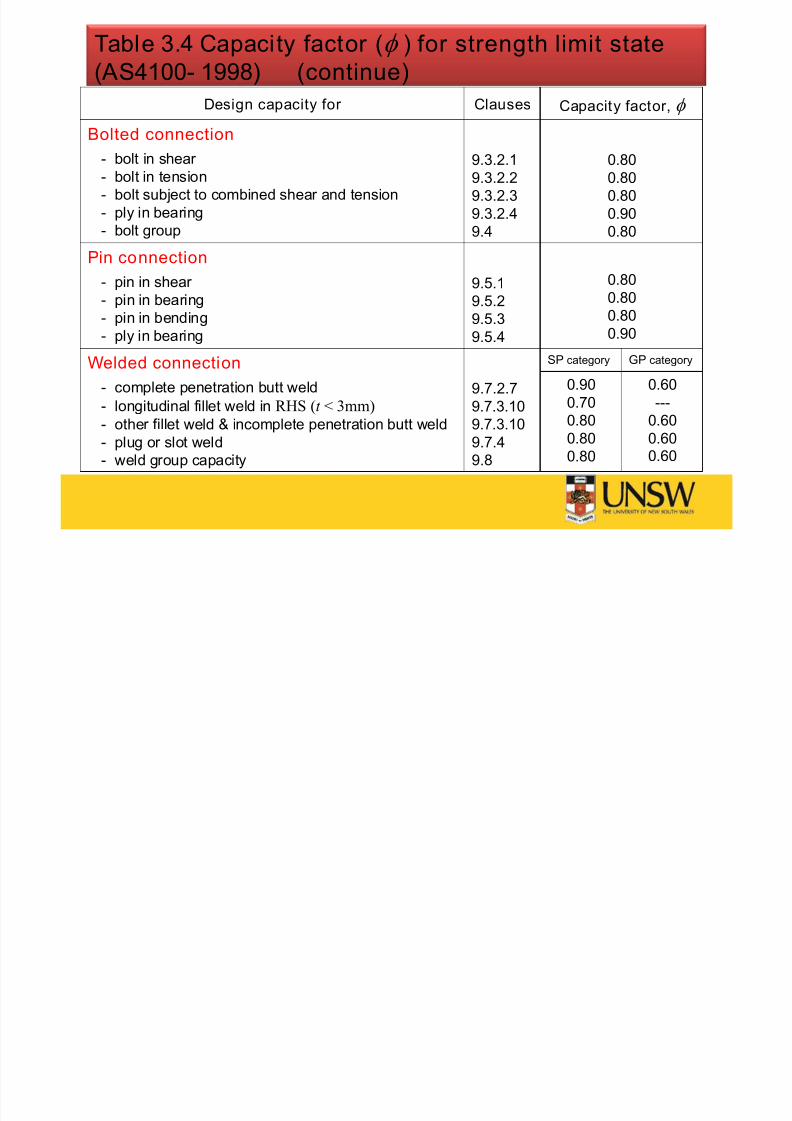
Table 3.4 Capacity factor ( ) for strength limit state
( AS4100- 1998) (continue)
Design capacity for Clauses Capacity factor,
Bolted connection
- bolt in shear
- bolt in tension
- bolt subject to combined shear and tension- ply in bearing
- bolt group
9.3.2.1
9.3.2.2
9.3.2.39.3.2.4
9.4
0.80
0.80
0.800.90
0.80
Pin connection
- pin in shear
- pin in bearing- pin in bending
- ply in bearing
9.5.1
9.5.29.5.3
9.5.4
0.80
0.800.80
0.90
Welded connection
- complete penetration butt weld- longitudinal fillet weld in RHS (t < 3mm)
- other fillet weld & incomplete penetration butt weld
- plug or slot weld
- weld group capacity
9.7.2.79.7.3.10
9.7.3.10
9.7.4
9.8
SP category GP category
0.90
0.70
0.80
0.80
0.80
0.60
---
0.60
0.600.60

7/23/2019 Lecture Note 1 (Steel)
http://slidepdf.com/reader/full/lecture-note-1-steel 24/30
- Stability limit state:
o {0.9G} (for combination that produce net stabilising)
o {1.35G}
o {1.2G,1.5Q}
o {G, E u, c Q}, where c is the combination factor (Table 4.1, AS1170)
o {1.2G, S u, c Q}, where S u can be {W u , F sn , 1.2 or 1.5F lp, 1.2F pnd , 1.2F gw}(clause 4.2.2 and 4.2.3, AS1170[1].0)
- Strength limit state:
o {1.35G}
o {1.2G,1.5Q}
o {0.9G, W u}
o {G, E u, c Q}
o {1.2G, S u, c Q}
- Serviceabil ity limit state: combinations may include one or a number
of the loads {G, s Q, l Q, W s , E s} using the short-term ( s ) and long-
term ( l ) factors given in Table 4.1.
Combinations of actions (Section 4, AS/NZS1170[1]. 0)
7/23/2019 Lecture Note 1 (Steel)
http://slidepdf.com/reader/full/lecture-note-1-steel 25/30
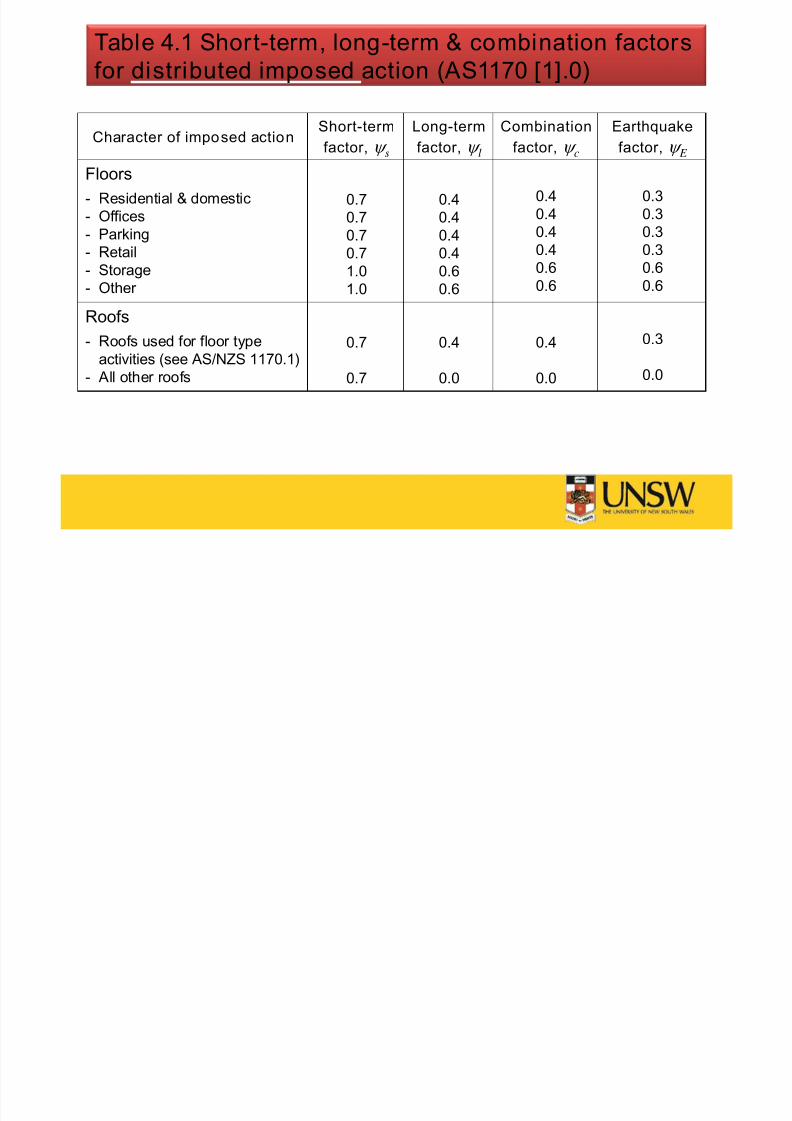
Table 4.1 Short-term, long-term & combination factors
for distributed imposed action ( AS1170 [1].0)
Character of imposed actionShort-term
factor, s
Long-term
factor, l
Combination
factor, c
Earthquake
factor, E
Floors
- Residential & domestic- Offices
- Parking
- Retail
- Storage
- Other
0.70.7
0.7
0.7
1.0
1.0
0.40.4
0.4
0.4
0.6
0.6
0.40.4
0.4
0.4
0.6
0.6
0.30.3
0.3
0.3
0.6
0.6
Roofs
- Roofs used for floor type
activities (see AS/NZS 1170.1)
- All other roofs
0.7
0.7
0.4
0.0
0.4
0.0
0.3
0.0
T bl 4 1 Sh l & bi i f
7/23/2019 Lecture Note 1 (Steel)
http://slidepdf.com/reader/full/lecture-note-1-steel 26/30
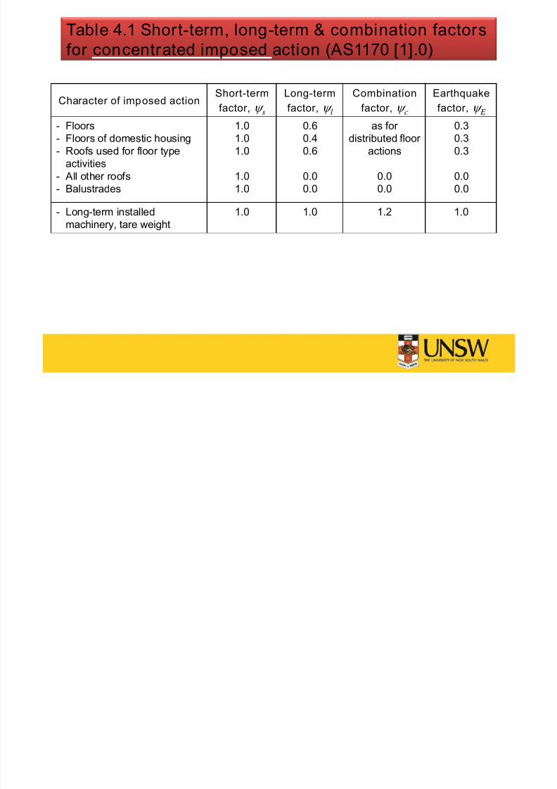
Table 4.1 Short-term, long-term & combination factors
for concentrated imposed action ( AS1170 [1].0)
Character of imposed actionShort-term
factor, s
Long-term
factor, l
Combination
factor, c
Earthquake
factor, E
- Floors
- Floors of domestic housing- Roofs used for floor type
activities
- All other roofs
- Balustrades
1.0
1.01.0
1.0
1.0
0.6
0.40.6
0.0
0.0
as for
distributed floor actions
0.0
0.0
0.3
0.30.3
0.0
0.0
- Long-term installedmachinery, tare weight
1.0 1.0 1.2 1.0
7/23/2019 Lecture Note 1 (Steel)
http://slidepdf.com/reader/full/lecture-note-1-steel 27/30
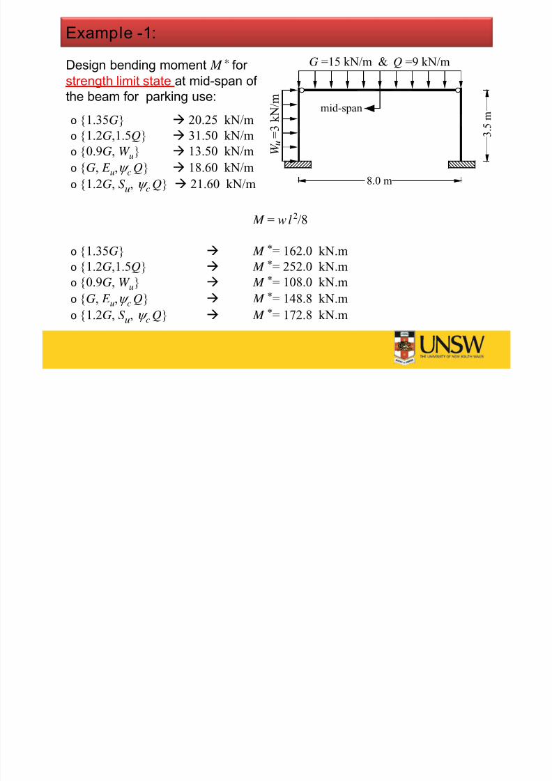
Design bending moment M
* for
strength limit state at mid-span of
the beam for parking use:
o {1.35G} 20.25 kN/m
o
{1.2G,1.5Q}
31.50 kN/mo {0.9G, W u} 13.50 kN/m
o {G, E u, c Q} 18.60 kN/m
o {1.2G, S u, c Q} 21.60 kN/m
Example -1:
G =15 kN/m & Q =9 kN/m
3 . 5 m
8.0 m
W
= 3 k N / m
u
mid-span
M = w l 2/8
o {1.35G} M *= 162.0 kN.m
o {1.2G,1.5Q} M *= 252.0 kN.m
o {0.9G, W u} M *= 108.0 kN.m
o {G, E u, c Q} M *= 148.8 kN.m
o {1.2G, S u, c Q} M *= 172.8 kN.m
7/23/2019 Lecture Note 1 (Steel)
http://slidepdf.com/reader/full/lecture-note-1-steel 28/30
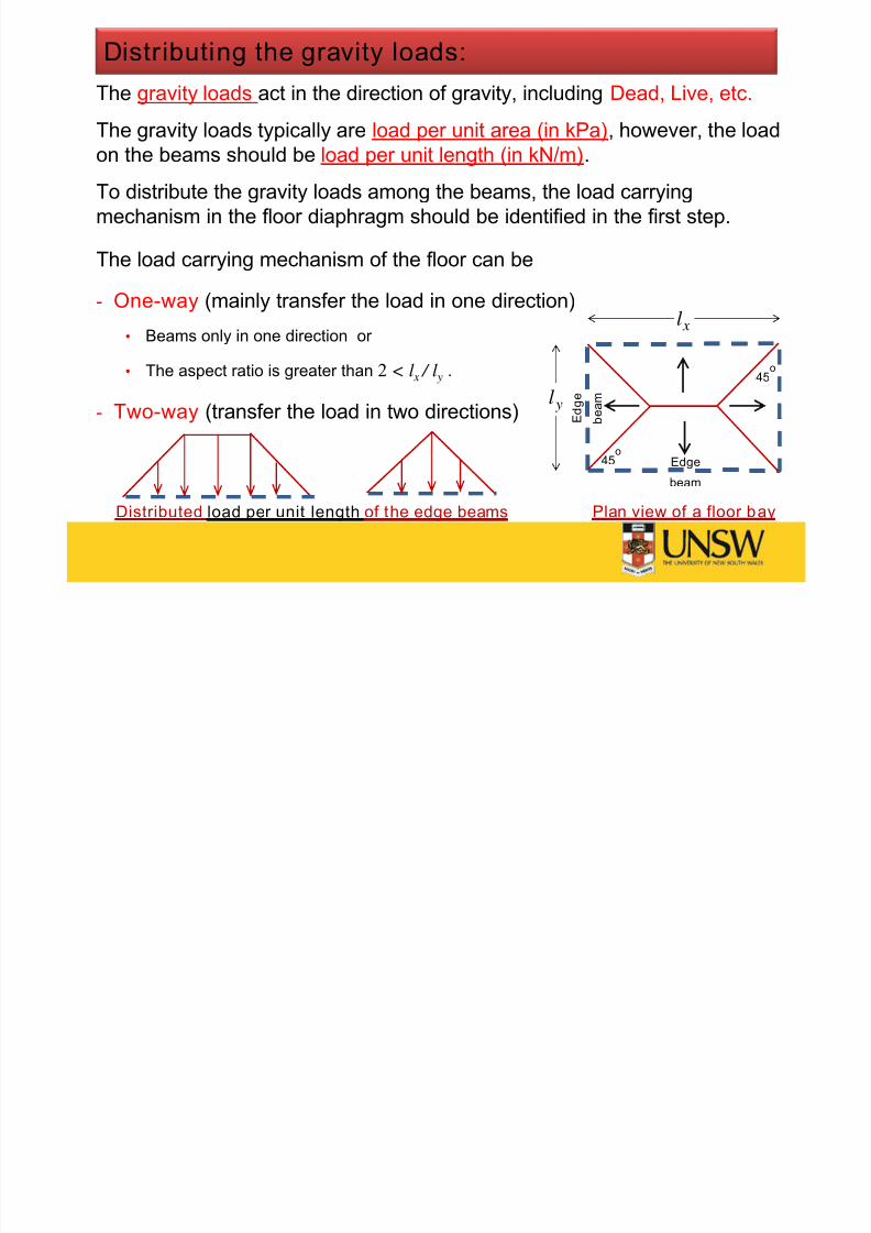
The gravity loads act in the direction of gravity, including Dead, Live, etc.
The gravity loads typically are load per unit area (in kPa), however, the load
on the beams should be load per unit length (in kN/m).
To distribute the gravity loads among the beams, the load carrying
mechanism in the floor diaphragm should be identified in the first step.
The load carrying mechanism of the floor can be
- One-way (mainly transfer the load in one direction)
• Beams only in one direction or
• The aspect ratio is greater than 2 < l x / l y .
- Two-way (transfer the load in two directions)
Distributing the gravity loads:
Plan view of a floor bay
xl
yl
Edge
beam
E d g e
b e a m
45o
45o
Distributed load per unit length of the edge beams

7/23/2019 Lecture Note 1 (Steel)
http://slidepdf.com/reader/full/lecture-note-1-steel 29/30
Type of floor diaphragm:
Steel w ire
meshConcreteslab
Concrete slab
JoistSteelsheet
Steel w iremesh
Steelbeam
Stud
connectors
Steel beam
Concrete slab
Steelsheet
Concrete slab
One-way load transfer
T f fl di h ( ti )
7/23/2019 Lecture Note 1 (Steel)
http://slidepdf.com/reader/full/lecture-note-1-steel 30/30
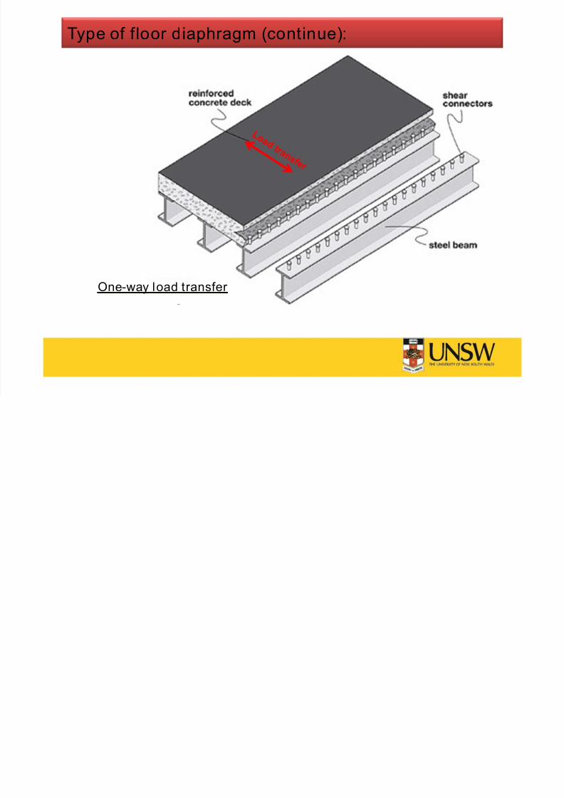
Type of floor diaphragm (continue):
One-way load transfer