Embed Size (px)
Citation preview

Department of Physics and Astronomy
University of Missouri Yun Zhang
It is hard to overemphasize the importance of practical demonstrations for
a true and deep understanding of physics. While it is of course very
important to understand the fundamental laws and relationships of physics
in their theoretical aspects, perhaps nothing like a practical demonstration
can bring them to life for a student of physics. Practical demonstrations of
the laws of physics make clear to students the power of physics to
systematize the seemingly random phenomena, and the power of our own
mind to make sense of them.

1
Part I: Electricity and Magnetism ................................................................................................. 2 1. Charging by Contact ....................................................................................................................... 2 2. Charged Balloon ............................................................................................................................ 2 3. Charged Rolling Coke Can .............................................................................................................. 2 4. Deflected water stream ................................................................................................................. 2 5. Flying Aluminum Pans, Flying Popcorns ......................................................................................... 3 6. Faraday cage .................................................................................................................................. 3 7. Temperature Dependence of Resistance ........................................................................................ 4 8. Variable Parallel Plate Capacitor .................................................................................................... 4 9. Deflection of Moving Charges in a Magnetic Field .......................................................................... 5 10. Current Balance ........................................................................................................................... 5 11. Magnetic Induction: Faraday’s Law .............................................................................................. 6 12. Jumping Ring ............................................................................................................................... 6 13. Magnet Down the Tube ............................................................................................................... 7 14. Magnetic Braking 2 ...................................................................................................................... 8 15. Tesla Coil/Hand Held Tesla Coil .................................................................................................... 9 16. Motor/Hand-‐Cranked Generator ................................................................................................. 9 17. Magnetic Levitation ................................................................................................................... 10 18. Superconductivity Levitation ..................................................................................................... 10
Part 2: Optics ............................................................................................................................. 11 1. Blackboard Optics Kit ................................................................................................................... 11 2. Large Plane Mirrors ..................................................................................................................... 11 3. Plane Mirrors at 90 Degrees ......................................................................................................... 11 4. A large Concave Mirror ................................................................................................................ 12 5. Bulb in the Socket ........................................................................................................................ 13 6. A large Convex Mirror .................................................................................................................. 13 7. Mirage ......................................................................................................................................... 14 8. Light Pipe ..................................................................................................................................... 14 9. Polarizing Sheets ......................................................................................................................... 15 10. Single Slit Diffraction ................................................................................................................. 15 11. Diffraction Gratings ................................................................................................................... 15
Part 3: Modern Physics .............................................................................................................. 16 1. Electron Diffraction ..................................................................................................................... 16 2. Radiometer ................................................................................................................................. 16 3. Cloud Chamber ............................................................................................................................ 16 4. Fusion in the Sun ......................................................................................................................... 17
Part 4: Other Demos .................................................................................................................. 18 1. Jacob’s Ladder ............................................................................................................................. 18 2. A Large Rotary Parallel Plate Capacitor ........................................................................................ 18 3. Magnetic Fields ........................................................................................................................... 18 4. A large Model Electric Generator ................................................................................................. 19 5. Optical Activity ............................................................................................................................ 19 6. Pin Hole Diffraction ..................................................................................................................... 19 7. Double Slit Interference ............................................................................................................... 19 8. Multiple Slit Interference ............................................................................................................. 19

2
Part I: Electricity and Magnetism
1. Charging by Contact
A rubber rod (-‐) is rubbed with wool (+); a glass rod (+) is rubbed with silk (-‐) A white plastic rod is rubbed with cloth (works the best). The charged rod is used to pick up paper crumbs. The charged rod is used to charge an electroscope.
2. Charged Balloon
Balloons are charged by rubbing briskly on the dry air. The charged balloon will then stick to the chalk board or hair because of the induced charge produced.
3. Charged Rolling Coke Can
A white plastic rod is rubbed with cloth. The charged plastic rod is brought near an empty coke can, the rod being held parallel to the long axis of the can. Charges of opposite sign are then attracted to the near side of the can, leaving charges of like sign on the far side of the can. From the inverse square law, the (attractive) force on the near side exceeds the (repulsive) force on the far side, causing the can to roll toward the rod.
4. Deflected water stream
A charged plastic rod is brought near a fine water stream issuing from an upside down dripping bottle. The stream of water is deflected toward the rod. (Not sure whether students can see the deflection.)

3
5. Flying Aluminum Pans, Flying Popcorns
This demonstration utilizes a Van de Graff generator. Aluminum pans sit on top of the dome. When the dome and the pans are charged after the Van de Graff is turned on, the repulsive force between the pans carrying like charges makes the pans fly. Replace the aluminum pans with a Styrofoam cup holding packing peanuts inside. After the Van de Graff is turned on for a short time, the packing peanuts fly out. A banana plug cord is used to discharge the Van de Graff. One end of this cord is connected to the ground of the Van de Graff. Bring the other end to touch the globe, and the globe is discharged.
6. Faraday cage
A small radio is turned on. When the Faraday cage is placed over the radio, the electromagnetic field is shielded, and as a result no radio signal is received by the radio. When the cage is taken away, the radio plays again.

4
7. Temperature Dependence of Resistance
A copper wire wound around a dowel rod is connected in series with a 12V light bulb. After the rod is immersed in liquid nitrogen, the light bulb glows more brightly. This effect occurs because of the decrease of resistivity of copper as the temperature is decreased.
The demonstration is repeated but using a large collection of carbon resistors connected in parallel at the end of a wire. The wire is connected in series with the 12V light bulb. When the carbon resistors are immersed in liquid nitrogen, the light bulb becomes dimmer.
8. Variable Parallel Plate Capacitor
In this demonstration, a parallel plate capacitor is first charged using a DC power supply (not shown in the picture). Then the DC power supply is disconnected from the capacitor. This leaves the amount of charges on the capacitor fixed. Then the capacitance of the capacitor can be changed in two ways: (1) change the separation between the two plates; or (2) insert a dielectric sheet between the two plates. While the capacitance is varied, the potential difference between the plates is measured by an electrometer. The electrometer is connected to a project-‐meter, which is placed on a projector so that the reading of the electrometer can by shown on a screen.
semiconductors
Most metals

5
9. Deflection of Moving Charges in a Magnetic Field
A glass tube with sharp metal tips on both ends sits on a pedestal. When a hand held Tesla Coil is placed close to one end, the high voltage generated by the Tesla Coil produces a visible electron beam in the tube. When a magnet is placed nearby, the electron beam visibly deflects. If the magnetic poles are flipped, the electron beam deflects in the opposite direction.
10. Current Balance
Using a laser-‐beam is aimed at the mirror of the apparatus, the apparatus can be used to show that wires carrying current attract or repel depending upon the relative current direction. Students observe the deflection of the laser beam on the wall when the current is applied to the wires of the apparatus. Parallel Currents
Anti-‐parallel Currents

6
11. Magnetic Induction: Faraday’s Law This demonstration is placed on a projector to show magnetic induction. If a magnet moves toward the coil, the pointer on the ammeter deflects, indicating an electric current flowing in the coil. If the magnet stays at rest in the coil, the pointer does not deflect. If the magnet moves away from the coil, the pointer deflects in the opposite way, indicating a current in the opposite direction flowing in the coil. If the magnet moves toward or away from the coil more quickly, the induced electric currents are larger.
12. Jumping Ring
A toroidal ring of wire is connected to a transformer which in turn is connected to an AC power outlet. The transformer controls the voltage supplied to the toroidal ring of wire and has a switch.
A small light bulb is connected to a metal ring. This ring is placed on top of the core of the toroid. The transformer voltage is set at below 60 volts. When the switch on the transformer is closed, the light bulb lights up due to magnetic induction.
When a copper (aluminum) ring is placed on the toroid and the switch on the transformer is closed, the ring will jump in the air. When another ring of the same diameter but with a slit cut out of it is placed on the toroid, it will not jump when the switch is closed. (The voltage of the transformer must not exceed 110 volts. Or the fuse in the transformer will blow.)
Discussion: this demonstration is similar to the following situation when the switch is closed (though the power source is DC). When the switch is open, there is no current in the coil and no magnetic field is present. When the switch in the circuit is closed, a current is established in the coil. From RHR-‐2, the magnetic field asso-‐ciated with the current in the coil leaves the bottom of the coil and enters the top of the coil (see drawing below). In other words, when there is a current in the coil, the bottom of the coil acts like the north pole of a bar magnet, and the top of the coil acts like the south pole of a bar magnet. The magnetic field of the coil causes a magnetic flux through the metal ring.
Metal ring
Switch
Battery
Iron core
Coil
+ –
7
In the very short time that it takes for the current to rise from zero to its steady value, the magnetic field associated with the current also rises from zero to its steady value. As the magnetic field increases, the magnetic flux through the metal ring changes, and there is an induced voltage and an induced current around the ring. From Lenz's law, the polarity of the induced voltage will be such that it opposes the changing flux through the metal ring. The induced magnetic field of the metal ring will be directed upward through the ring to subtract from the magnetic field of the coil that points downward through the ring. This is illustrated in the figure at the right. To preserve clarity, the iron core and a portion of the circuit have not been shown. The induced magnetic field of the metal ring is similar to that of a bar magnet, with the north pole above the ring, and the south pole below the ring. Thus, the situation is similar to that of two bar magnets with their south poles next to each other. The two south poles repel, and the ring "jumps" upward.
13. Magnet Down the Tube
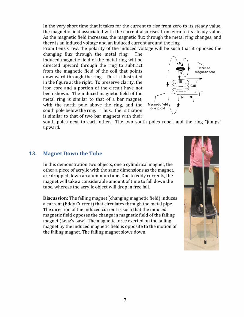
In this demonstration two objects, one a cylindrical magnet, the other a piece of acrylic with the same dimensions as the magnet, are dropped down an aluminum tube. Due to eddy currents, the magnet will take a considerable amount of time to fall down the tube, whereas the acrylic object will drop in free fall. Discussion: The falling magnet (changing magnetic field) induces a current (Eddy Current) that circulates through the metal pipe. The direction of the induced current is such that the induced magnetic field opposes the change in magnetic field of the falling magnet (Lenz’s Law). The magnetic force exerted on the falling magnet by the induced magnetic field is opposite to the motion of the falling magnet. The falling magnet slows down.
Magnetic field due to coil
Coil
+ –
I
S
N
S
NInduced
magnetic field
I

8
• Magnetic Braking 1
A pendulum bob made of copper is placed between the poles of an electromagnet. When the pendulum is set in motion and current then put into the electromagnet, the pendulum will stop very quickly due to the induced eddy current in the bob. If a copper bob with slits is used instead, no (or a tiny amount of) eddy current will be induced and the pendulum will almost swing as it normally would.
Discussion: The figure shows the directions of the Eddy Currents and the magnetic forces on the sheet of metal when it enters and leaves the region where an external magnetic field exists. In each case, the direction of the magnetic force is opposite to the motion of the sheet of metal, thus providing a braking effect.
14. Magnetic Braking 2
A pendulum is used with three different aluminum bobs, once being a solid bob, one having some open slits, and the third have many open slits. The pendulum is swung between the poles of a variable-‐gap magnet. The holder has two slits so that two bobs can swing at the same time and their differences compared. The solid pendulum stops almost immediately. The one with many slits swings almost like a normal pendulum. The bob with some slits will swing and eventually stop but will take less time to do so as compared with the bob with many slits.

9
15. Tesla Coil/Hand Held Tesla Coil
Tesla coils generate high frequency high voltage, which is used to light bulbs without touching. Discussion: the strong electric field generated by the high voltage drives electrons in the light bulb, creating electric current.
16. Motor/Hand-‐Cranked Generator
This device can function as a motor or a hand-‐cranked generator. If the leads are connected to a battery, the handle rotates. If the leads are connected to a light bulb, cranking the handle makes the bulb light up. The faster the handle is cranked, the more brightly the bulb lights up.
• • •

10
17. Magnetic Levitation In this apparatus a permanent magnet is suspended close to an aluminum disk. As the aluminum disk spins, eddy currents are produced, creating a magnetic field that repels the magnet.
18. Superconductivity Levitation
In this demonstration, a superconductor is used to demonstrate the Meissner Effect (that a material in a superconducting state will repel a magnet.) A slab of YBa2Cu3O7 superconducting material is dropped into a small container full of liquid nitrogen and allowed to reach thermal equilibrium. Using tweezers, a small cobalt-‐samarium magnet is placed on top of the superconducting slab and is observed to float a few millimeters above the superconductor.

11
Part 2: Optics
1. Blackboard Optics Kit
The kit includes convex and concave spherical mirrors, converging\diverging lenses, and prisms. Parallel rays are incident on mirrors\lenses to illustrate the converging\diverging actions, and the real\virtual focal points. The prism can be utilized to illustrate partial refraction\reflection and total internal reflection, and dispersion.
2. Large Plane Mirrors
These large plane mirrors can be used to demonstrate reflection of light.
3. Plane Mirrors at 90 Degrees
Two plane mirrors are mounted on a wooden base and jointed together at a 90 degree angle. An object placed in front of the mirrors produces three images.

12
4. A large Concave Mirror
Students can walk toward this mirror to explore different imaging characteristics of a concave mirror at different object distances.
• • • • • • • • • • •
Discussion:
Case 1: Object is far from a concave mirror: Image is inverted, smaller
Case 2: Object is very close to a concave mirror: Image is upright, larger
This case: the person cannot see her image since the image is behind her.
Case 1:
Case 2:

13
5. Bulb in the Socket
This demonstration utilizes an apparatus constructed from wood on one end of which is placed a spherical concave mirror. At the other end a light socket is placed so as to be at the center of curvature of the mirror. Hidden underneath this socket is another socket with a light bulb that is upside down. When the hidden light bulb is turned on, it appears as though it were in the socket on top.
6. A large Convex Mirror
A convex mirror always produces virtual (and upright) images that are reduced in size.

14
7. Mirage
In the MIRAGE apparatus, two concave spherical mirrors fit together so that the focal point of the lower mirror is at the center of the upper one and the focal point of the upper mirror is at the center of the lower one. An object placed on the surface of the lower mirror produces a real image in the plane of the hole in the upper mirror. This apparatus is passed around the audience.
8. Light Pipe
A bent glass rod is used to illustrate total internal reflection. Light is fed into the rod using a laser pointer.

15
9. Polarizing Sheets
One polarizing sheet is placed on an overhead projector and the reduction of intensity is observed. A second sheet is then placed over the first and rotated relative to the first to show the gradual change in intensity. In particular when the second is perpendicular to the first, no light is transmitted through the second.
A third polarizing sheet is inserted between the original two, with its axis at 45 degrees with respect to the original two sheets. Light can then be observed to pass through the three sheets. One polarizing sheet: reduces light (unpolarized) intensity by ½.
Two polarizing sheets at 90 degrees: completely block the light.
10. Single Slit Diffraction
In this demonstration a variable slit is placed in a laser beam and slit spacing decreased. It is observed that the radiation pattern spreads out.
11. Diffraction Gratings
A laser beam passing through a diffraction grating produces a diffraction pattern.

16
Part 3: Modern Physics
1. Electron Diffraction
This demonstration utilizes the Electron Diffraction Tube apparatus. When in operation and at the appropriate voltage level, a series of diffraction circles are observed on the front viewing screen of the apparatus. When the voltage increases, the diffraction circles move toward the center.
2. Radiometer Four vanes each having one side black and one side white, are mounted on a pivot which is enclosed in a partially evacuated glass bulb. As light strikes it from the side, the absorbed photons heat the black side which heats the surrounding air molecules which then bounce off the vane imparting momentum.
3. Cloud Chamber
The apparatus is placed on a bed of dry ice and the inside bottom is wetted with a 95% ethanol mixture. After about twenty minutes ionization tracks are clearly visible and the audience is asked to leave their seats and observe the tracks in the chamber.
Preparations instructions:
17
(1) Crush about 15 lbs of dry ice and place it on top of the black plastic sheet covering the insulation pad.
(2) Place the chamber on top. Cover the gaps on the sides with the black elastic belt to reduce evaporation of dry ice.
(3) Pour the liquid (methanol, ethanol…-‐ does not matter as long as water is less than 20%) into the chamber, directly onto the metal plate until it is completely covered. Be sure to saturate the black felt sheets as well. They help keep the atmosphere saturated.
(4) Place the cover over the chamber and allow equilibrium to establish (it takes about twenty minutes). Moving the chamber upsets the equilibrium. But if the chamber is set up on a cart with good wheels, after moving the chamber equilibrium can be restored within 10 to 15 minutes.
(5) Use the slide projector to illuminate through the window area. Lots of activity can be seen in the vapor over the liquid without using any radioactive sources. Sources can be mounted on top of corks and placed in the liquid so the radiation travels horizontally through the vapor. The tracks don’t make it very far, but are visible (Beta sources work the best).
4. Fusion in the Sun
This demonstration is a chapter in a computer generated movie “The Universe” by the History Channel. This chapter runs about 10 minutes.
18
Part 4: Other Demos
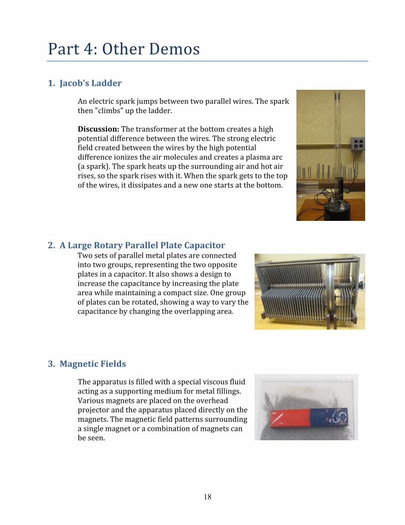
1. Jacob’s Ladder
An electric spark jumps between two parallel wires. The spark then "climbs" up the ladder. Discussion: The transformer at the bottom creates a high potential difference between the wires. The strong electric field created between the wires by the high potential difference ionizes the air molecules and creates a plasma arc (a spark). The spark heats up the surrounding air and hot air rises, so the spark rises with it. When the spark gets to the top of the wires, it dissipates and a new one starts at the bottom.
2. A Large Rotary Parallel Plate Capacitor Two sets of parallel metal plates are connected into two groups, representing the two opposite plates in a capacitor. It also shows a design to increase the capacitance by increasing the plate area while maintaining a compact size. One group of plates can be rotated, showing a way to vary the capacitance by changing the overlapping area.
3. Magnetic Fields
The apparatus is filled with a special viscous fluid acting as a supporting medium for metal fillings. Various magnets are placed on the overhead projector and the apparatus placed directly on the magnets. The magnetic field patterns surrounding a single magnet or a combination of magnets can be seen.

19
4. A large Model Electric Generator In this wooden model generator, a coil is placed between two magnetic poles. When the coil is turned, the pointer in the ammeter deflects, indicating an electric current is generated. If the coil is turned in the opposite direction, the pointer in the ammeter deflects in the opposite direction.
5. Optical Activity
In this demonstration a beaker is filled with Karo corn syrup and placed on a cardboard mask with a hole about two-‐thirds the diameter of the beaker to block out excess light. A polarizing sheet is placed on an overhead projector and the mask and beaker placed over the sheet. A second polarizing sheet is then placed over the top surface of the beaker, and the audience observes that light emerging from the top surface has different planes of polarization for different colors.
6. Pin Hole Diffraction
A laser beam is focused on a small pin hole. The diffraction pattern is then viewed on a distance screen and is observed to be a series of alternating concentric dark and light rings.
7. Double Slit Interference
Three double slits with different spacings are placed in a laser beam and the resulting pattern shown on a distant screen. The interference pattern is spread more apart when the slits are closer together.
8. Multiple Slit Interference
Laser light is passed through three slits, four slits, and five slits and the resulting pattern shown on a distant screen. It is observed that the pattern spreads out more (becomes sharper) as the number of slits is increased.


![[301] Variables and Expressions · Today's Outline Review • Operator Precedence Expressions, Variables, and Assignments Demos Bugs Demos Naming variables Demos](https://img.dokumen.tips/doc/110x75/60353c1a1ded2c381409d526/301-variables-and-expressions-todays-outline-review-a-operator-precedence-expressions.jpg)