Embed Size (px)
Citation preview

Lecture 8 Current and ResistanceLooking forward at …
• the meaning of electric current, and how charges move in a conductor.
• how to use a simple model to understand the flow of current in metals.
• how to calculate the resistance of a conductor from its dimensions and its resistivity or conductivity.
• how an electromotive force (emf) makes it possible for current to flow in a circuit.
• how to do calculations involving energy and power in circuits.
© 2016 Pearson Education Inc.

Introduction• Electric circuits contain
charges in motion.
• In a flashlight, the amount of current that flows out of the bulb is the same as the amountthat flows into the bulb.
• It is the energy of the charges that decreases as the current flows through light bulbs.
• Circuits are at the heart of modern devices such as computers, televisions, and industrial power systems.
© 2016 Pearson Education Inc.

Current• A current is any motion of charge
from one region to another.
• A small cylinder with base A and length dx has volume dV=Adx. In the volume there are dN= ndV particles with a charge of dQ=nqAdx . If all of them cross the right base in time dt, their speed is vd=dx/dt.
• If " = $%&', (current density)
• ( = " ) * (like electric flux). In general ( = ∫ " ) ,*
© 2016 Pearson Education Inc.
A
dxDrift speed in metals is tiny vd= 10-4 m/s.
Compare with thermal speed vth= 104 m/s!

Direction of current flow• A current can be produced by positive or negative charge
flow.
• Conventional current is treated as a flow of positive charges.
• In a metallic conductor, the moving charges are electrons —but the current still points in the direction positive charges would flow.
© 2016 Pearson Education Inc.

Signs of charge carriers• In general, a conductor may
contain several different kinds of moving charged particles.
• An example is current flow in an ionic solution.
• In the sodium chloride solutionshown, current can be carried by both positive sodium ions and negative chlorine ions
• The total current I is found by adding up the currents due to each kind of charged particle.
© 2016 Pearson Education Inc.

What causes the current?• What makes charged particles to move? !" = $%
• Now the system is NOT electrostatic: % may not be 0 inside a conductor.
• So each charge accelerates with ' = ()% and its velocity grows
with time: * = *+ + ()%-.
• Wait! Then the current grows with time when we have non-zero %! Wrong!
• The current stays the same, because the velocity of the charges is not growing. It is not growing, because the charges dissipate the kinetic energy they have gained (transfer it to the lattice of theconductor) in the form of random lattice oscillations (heat).
© 2016 Pearson Education Inc.

Metallic conduction• Electrons in a conductor are free to move
through the crystal, colliding at intervals with the stationary positive ions (this is naïve).
• The motion of the electrons is analogous to the motion of a ball rolling down an inclined plane and bouncing off pegs in its path.
• We assume that after each collision the velocity is random. Then the average velocity in the direction of E, just after the collision is 0!

Resistivity
• !" =< ! >=< !'> + )*+ < ,> , <.> means average over all moving charged
particles.
• - = ./!" = 0)1234* + = 5+
• 5 is the conductivity, 6 = 1/5 is the resistivity
• The resistivity of a material is the ratio of the electric field in the material to the current density it causes:
• The next slide shows the resistivity of various types of materials.
© 2016 Pearson Education Inc.
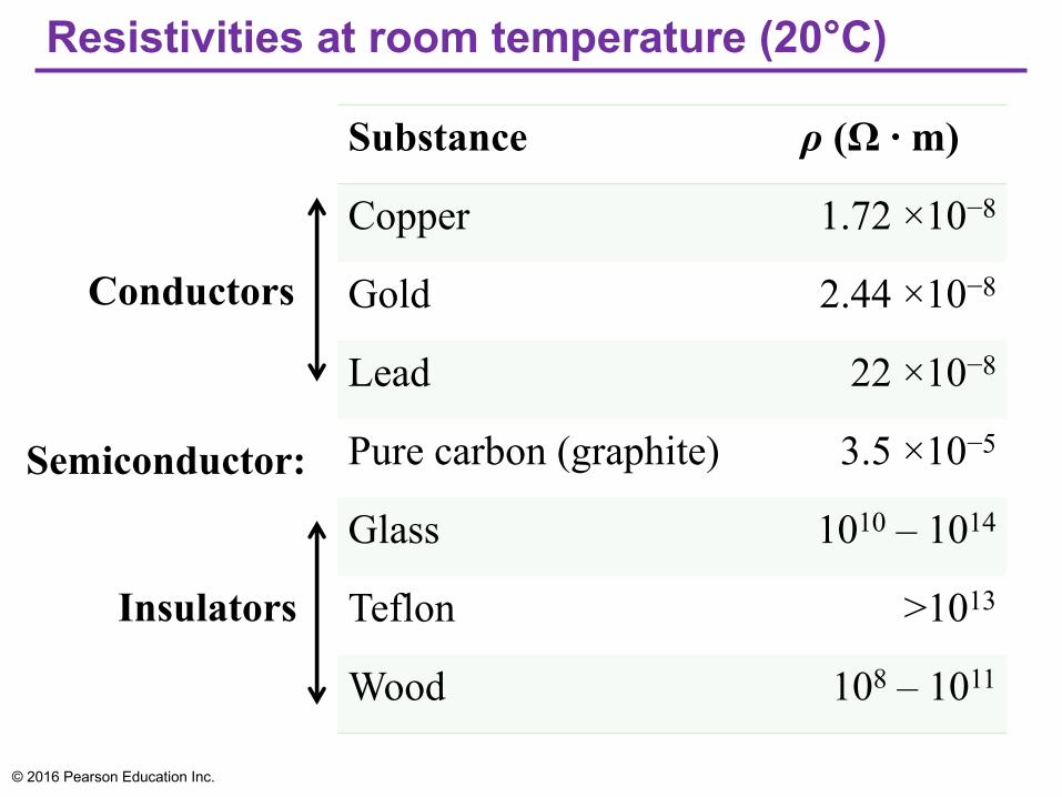
Resistivities at room temperature (20°C)
© 2016 Pearson Education Inc.
Substance ρ (Ω · m)
Copper 1.72 ×10⁻⁸
Gold 2.44 ×10⁻⁸
Lead 22 ×10−8
Pure carbon (graphite) 3.5 ×10⁻⁵
Glass 1010 – 1014
Teflon >1013
Wood 108 – 1011
Conductors
Insulators
Semiconductor:

Circuit boards and resistivity• The copper “wires,” or traces, on this circuit board are printed
directly onto the surface of the dark-colored insulating board.
• Even though the traces are very close to each other, the board has such a high resistivity that essentially no current can flow between the traces.
© 2016 Pearson Education Inc.
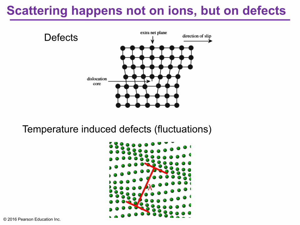
Scattering happens not on ions, but on defects
© 2016 Pearson Education Inc.
Defects
Temperature induced defects (fluctuations)
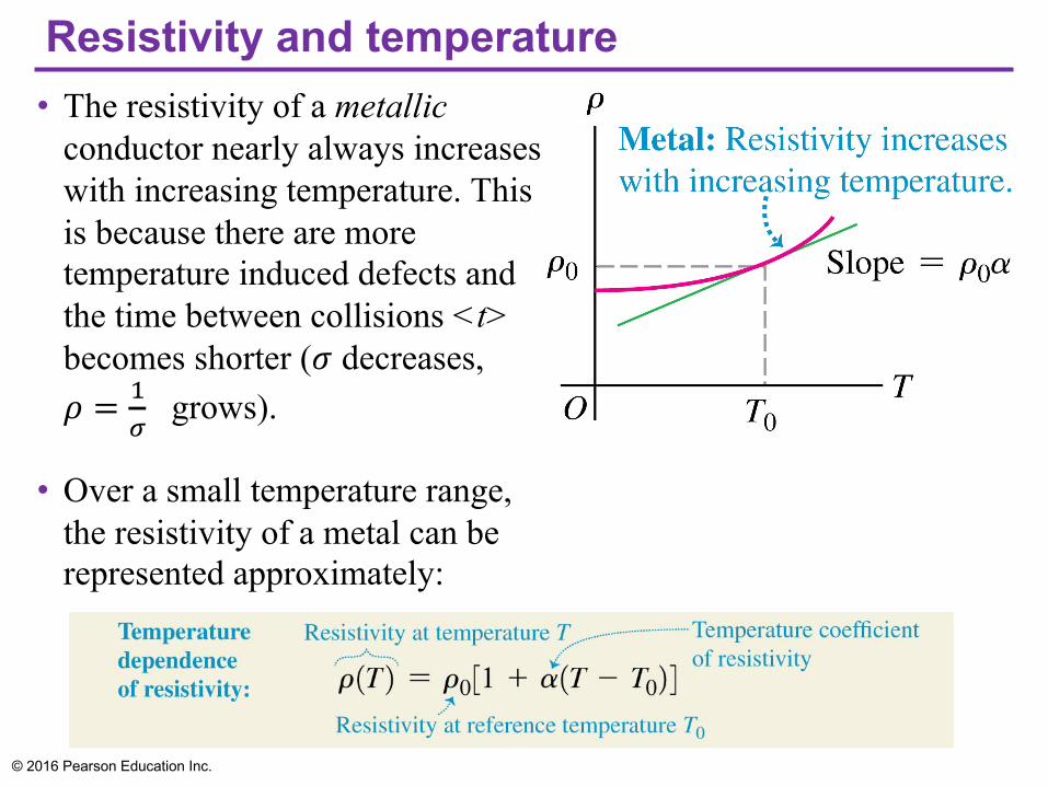
Resistivity and temperature• The resistivity of a metallic
conductor nearly always increases with increasing temperature. This is because there are more temperature induced defects and the time between collisions <t> becomes shorter (! decreases, " = $
% grows).
• Over a small temperature range, the resistivity of a metal can be represented approximately:
© 2016 Pearson Education Inc.

Temperature coefficients of resistivity
© 2016 Pearson Education Inc.
Material α [(°C)−1]Aluminum 0.00039
Carbon (graphite) −0.0005
Copper 0.00393
Iron 0.0050
Lead 0.0043
Silver 0.0038
Tungsten 0.0045

Resistivity and temperature• The resistivity of graphite (a semiconductor) decreases with
increasing temperature, since at higher temperatures, more electrons “shake loose” from the atoms and become mobile, i.e n (charge number density) is not constant, but grows with T.
• Measuring the resistivity of a small semiconductor crystal is a sensitive measure of temperature; this is the principle of a type of thermometer called a thermistor.
© 2016 Pearson Education Inc.

Superconductivity• Some materials show a
phenomenon called superconductivity.
• As the temperature decreases, the resistivity at first decreases smoothly, like that of any metal.
• Below a certain critical temperature Tc a phase transition occurs and the resistivity suddenly drops to zero.
• This is because the electrons form pairs that can move together without scattering and energy loss.
• Once a current has been established in a superconducting ring, it continues indefinitely without the presence of any driving field.
© 2016 Pearson Education Inc.

• From ! = #$, multiply by L, use that EL=V, J=I/A : V=RI, where the resistance of a conductor is R=#%/'
• This is Ohm’s law: V = IR.
Resistance and Ohm’s law
© 2016 Pearson Education Inc.

Resistors are color-coded for easy identification• This resistor has a resistance of 5.7 kΩ with a tolerance
of ±10%.
© 2016 Pearson Education Inc.

Ohmic resistors• For a resistor that obeys Ohm’s law, a graph of current as a
function of potential difference (voltage) is a straight line.
© 2016 Pearson Education Inc.
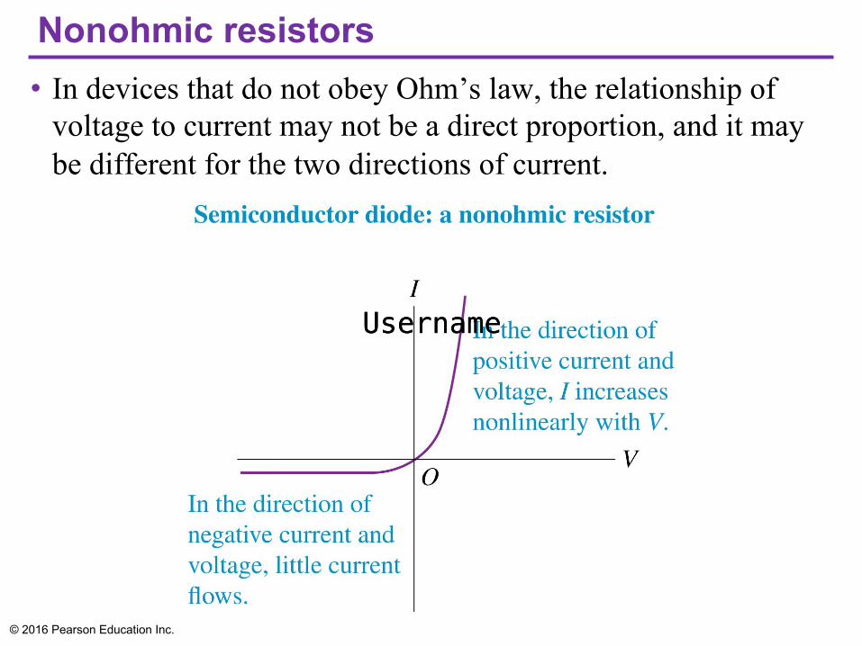
Nonohmic resistors• In devices that do not obey Ohm’s law, the relationship of
voltage to current may not be a direct proportion, and it may be different for the two directions of current.
© 2016 Pearson Education Inc.
UsernameUsername

Electromotive force and circuits• Just as a water fountain requires a pump, an electric circuit
requires a source of electromotive force to sustain a steady current.
© 2016 Pearson Education Inc.

Electromotive force and circuits• The influence that makes current flow from lower to higher
potential is called electromotive force (abbreviated emf and pronounced “ee-em-eff”), and a circuit device that provides emf is called a source of emf.
• Note that “electromotive force” is a poor term because emf is not a force but an energy-per-unit-charge quantity, like potential.
• The SI unit of emf is the same as that for potential, the volt (1 V = 1 J/C).
• A typical flashlight battery has an emf of 1.5 V; this means that the battery does 1.5 J of work on every coulomb of charge that passes through it.
• We’ll use the symbol (a script capital E) for emf.
© 2016 Pearson Education Inc.

Internal resistance• Real sources of emf actually contain
some internal resistance r. This takes into account not only charge scattering inside, but all processesthat dissipate the original non-electrostatic energy.
• The terminal voltage of the 12-V battery shown at the right is less than 12 V when it is connected to the light bulb.
© 2016 Pearson Education Inc.

Table 25.4 — Symbols for circuit diagrams
© 2016 Pearson Education Inc.

Potential changes• The figure shows how the
potential varies as we go around a complete circuit.
• The potential rises when the current goes through a battery, and drops when it goes through a resistor.
• Going all the way around the loop brings the potential back to where it started.
© 2016 Pearson Education Inc.

Energy and power in electric circuits• The box represents a circuit
element with potential difference Vab = Va − Vbbetween its terminals and current ! = #$
#% passing through it in the direction from a toward b. &'( = &) *+,
• If the potential at b is lower than at a, then there is a net transfer of energy out of the electric system (charges + E fields) to the circuit element (energy is converted to non-electrostatic type.)
• The time rate of energy transfer is power, denoted by - = #./#% , so
we write:
© 2016 Pearson Education Inc.

Power• The upper rectangle
represents a source with emfand internal resistance r,
connected by ideal wires to an external circuit represented by the lower box.
• Point a is at higher potential than point b, so Va > Vb and Vab is positive. Energy is transferred to the system of charges: P = VabI. For non-ideal battery:
© 2016 Pearson Education Inc.