Embed Size (px)
Citation preview

1
EE4900/EE6420 Digital Communications Suketu Naik
EE4900/EE6420: Digital Communications
Lecture 6
Modulation,
Demodulation
(Detection): Part 1

2
EE4900/EE6420 Digital Communications Suketu Naik
Block Diagrams of Communication System
Digital Communication System
Informatio
n (sound,
video, text,
data, …)
Transducer &
A/D ConverterModulator
Source
Encoder
Channel
Encoder
Tx RF
System
Output
Signal
D/A Converter
and/or output
transducer
DemodulatorSource
Decoder
Channel
Decoder
Rx RF
System
Channel

3
EE4900/EE6420 Digital Communications Suketu Naik
EE4900/EE6720: Digital Communications
Introduction

4
EE4900/EE6420 Digital Communications Suketu Naik
Digital Baseband Modulation Schemes
Baseband Modulation is done before the information
(bits) is sent out using a carrier signal
Popular methods for low data-rate are,
ASK: Amplitude Shift Keying
OOK: On-Off Keying
FSK: Frequency Shift Keying
ASK Signal
OOK Signal
FSK Signal

5
EE4900/EE6420 Digital Communications Suketu Naik
Digital Baseband Modulation Schemes
Baseband Modulation is done before the information
(bits) is sent out using a carrier signal
Popular methods for high data-rate are,
PCM: Pulse Code Modulation
PAM: Pulse Amplitude Modulation
PWM: Pulse Width Modulation
PPM: Pulse Position Modulation
BPSK: Binary Phase Shift Keying
QPSK: Quadrature Phase Shift Keying
O-QPSK: Offset Quadrature Phase Shift Keying
QAM: Quadrature Amplitude Modulation

6
EE4900/EE6420 Digital Communications Suketu Naik
Pulse Code Modulation (PCM)
PCM is commonly used for digital audio (Windows PCs,
CDs, digital telephony)
PCM: Analog signal (such as voice or music) is
converted to discrete samples and then quantized to bits
After quantization, companding (compressing and
expanding) takes place: μ-law in North America and
Japan and A-law in Europe and rest of the world

7
EE4900/EE6420 Digital Communications Suketu Naik
Pulse Code Modulation (PCM)
PCM Example
PCM Signal
Original Signal

8
EE4900/EE6420 Digital Communications Suketu Naik
Pulse Amplitude Modulation (PAM)
PAM is used in Digital TV, 10GBase-T Ethernet, LED
driver, Controls
PAM: Width is fixed, Amplitude varies
Original Signal
PAM Signal

9
EE4900/EE6420 Digital Communications Suketu Naik
Pulse Width or Duration Modulation (PWM or PDM)
PWM is used in Controls (motors, servos for robots,
power, audio, telecomm.),
PWM: Position is fixed, Width varies
Original Signal
PWM Signal

10
EE4900/EE6420 Digital Communications Suketu Naik
Pulse Position Modulation (PPM)
PPM is used in non-coherent RF comm., contactless
smart card, RFID tags, radio control, optical comm.
PPM: Width is fixed, Position varies
Original Signal
PPM Signal

11
EE4900/EE6420 Digital Communications Suketu Naik
Binary Phase Shift Keying (BPSK)
BPSK is commonly used in communications
BPSK: Phase of the baseband signal changes from 0 deg
to 180 deg (2 transitions)=1 bit per symbol
Original Signal
BPSK Symbol
Q (out of phase)
I (in phase)Phase Diagram 01

12
EE4900/EE6420 Digital Communications Suketu Naik
Quadrature Phase Shift Keying (QPSK)
QPSK (and O-QPSK) is commonly used in
communications
QPSK: Phase of the baseband signal changes from 45
deg, 135 deg, 225 deg, 315 deg (4 transitions)=2 bits per
symbol
Original Signal
QPSK Symbol
Q (out of phase)
I (in phase)Phase Diagram
11
10
01
00

13
EE4900/EE6420 Digital Communications Suketu Naik
8-PSK
8PSK = 8 phase transitions= 3 bits per symbol
Q (out of phase)
I (in phase)8-PSK Phase
Diagram
000
001
011
010
101
111
110
100

14
EE4900/EE6420 Digital Communications Suketu Naik
Quadrature Amplitude Modulation (QAM)
QAM (rhymes with Guam and VietNAM) is commonly
used in communications
QAM: Amplitude and Phase of the Baseband signal
changes, 16-QAM (16 transitions, 4-bits/symbol), 32-QAM
(5-bits/symbol), 64-QAM (64 transitions, 6-bits/symbol)
16-QAM
Phase Diagram
Q (out of phase)
I (in phase)

15
EE4900/EE6420 Digital Communications Suketu Naik
Quadrature Amplitude Modulation (QAM)
QAM Signal in Time-domain
8-QAM=8PSK

16
EE4900/EE6420 Digital Communications Suketu Naik
EE4900/EE6420: Digital Communications
Basics of
Modulation

17
EE4900/EE6420 Digital Communications Suketu Naik
Waveforms=Bits
M-ary (“emery”) digital communication system uses M
symbols to transmit log2(M) bits
Examples
BPSK: M=2, log2(M)=1 bit per symbol
Two symbols, one for each bit (0 and 1)
QPSK: M=4, log2(M)=2 bits per symbol
Four symbols, one for two bit pairs
(00, 01, 11, 10)
Binary PAM: M=2, 1 bit per symbol
8-PAM: M=8, 3 bits per symbol
16-QAM, 32-QAM, 64-QAM, 128-QAM: ?

18
EE4900/EE6420 Digital Communications Suketu Naik
Waveforms, Symbols, Basis Functions
M-ary communication uses M symbols
Symbols are created by changing amplitudes of basis
functions
Thus a waveform is a linear combination or weighted
sum of basis functions
This waveform can be called the baseband signal or the
modulating signal
The modulating signal modulates (multiplied with) the
carrier signal so that the carrier signal can now carry
“bits”
Basis functions > Symbols > Waveform

19
EE4900/EE6420 Digital Communications Suketu Naik
Signal Space and Basis Functions
Let’s represent the M waveforms as a signal (symbol) set
𝑺 = {𝒔𝟎 𝒕 , 𝒔𝟏 𝒕 , 𝒔𝟐 𝒕 , … , 𝒔𝑴−𝟏 𝒕 }with symbol time Ts
B=set of basis functions
Signal Space=Span{B}= linear
combination of basis functions
Baseband signal s(t) (with K=M)
𝒔(𝒕) =
𝒌=𝟎
𝑲−𝟏
𝒂𝒌∅𝒌(𝒕)
Energy 𝑬𝒌= 𝑻𝟏𝑻𝟐 ∅𝒌
𝟐 𝒕 𝒅𝒕
s0(t) s1(t) s2(t) s3(t) s4(t) s5(t) s6(t) s7(t)
Ts
Example
1) M=8 waveforms=8 signals (symbols)
2) Signal (symbol) set S contains 8
possible signals (symbols)
3) Each symbol represents 3-bits
e.g. bit patterns such as 101 or 100 are
mapped to specific symbols
4) s(t), the baseband signal, is the
linear combination of the basis
functions, constructed from symbols,
s0(t), …sM-1(t)
Example Baseband Signal s(t)
Basis FunctionAmplitude
2Ts 3Ts 4Ts …

20
EE4900/EE6420 Digital Communications Suketu Naik
Properties of Basis Functions
Orthogonality
න𝑻𝟏
𝑻𝟐
∅𝒊 𝒕 ∅𝒋 𝒕 𝒅𝒕 = 𝟎
Interpretation:
Multiply two different signals and integrate, the result is 0
Orthonormal Set
න𝑻𝟏
𝑻𝟐
∅𝒊 𝒕 ∅𝒋 𝒕 𝒅𝒕 = 𝜹 𝒊 − 𝒋 = ቊ𝟏 𝒊𝒇 𝒊 = 𝒋𝟎 𝒊𝒇 𝒊 ≠ 𝒋
Interpretation:
Multiply two different signals and integrate, the result is 0
Multiply two identical signals and integrate, the result is 1
Example: cos(2πt) sin(2πt)
1) Two orthogonal signals are transmitted together to reduce noise (e.g.
QPSK, QAM)
2) The detector (receiver) is designed based on orthonormality

21
EE4900/EE6420 Digital Communications Suketu Naik
Energy
Recall that baseband signal s(t) can be created from K
orthonormal functions as,
𝒔(𝒕) =
𝒊=𝟎
𝑲−𝟏
𝒂𝒌∅𝒌(𝒕)
Interpretation:
Constants ak are the components of K-dimensional vector so that s(t)
can be represented as K-dim vector S,
𝑺 = [𝒂𝟎 𝒂𝟏 𝒂𝟐…𝒂𝑲−𝟏]
Energy
𝑬 = න𝑻𝟏
𝑻𝟐
𝒔𝟐 𝒕 𝒅𝒕 =
𝒌=𝟎
𝑲−𝟏
𝒂𝒌𝟐
1) Energy in the signal s(t) is equal to the square of the Euclidean
distance between the K-dimensional point and the origin
2) This result is important for designing the detector (receiver)
Analog signal
representing
the bit stream
An example
[𝒂𝟎 𝒂𝟏 𝒂𝟐]
0
1
2
An example

22
EE4900/EE6420 Digital Communications Suketu Naik
EE4900/EE6420: Digital Communications
Modulation
And Detection

23
EE4900/EE6420 Digital Communications Suketu Naik
Approximation of Received Signal r(t)
Transmitted signal=s(t), Received signal=r(t), Noise=w(t)
r(t)=s(t) + w(t)
Goal: find the best approximation ො𝒓(t) to r(t) using basis functions
Why?
Because s(t) is corrupted by noise and we need to find an equivalent
of the corrupted s(t) or r(t) in Span{B}
Why?
-Span{B} contains the basis functions
-So that we can determine the symbols and hence the basis functions
Why?
Because the basis functions were used to create symbols which
represented the bits (information)
Symbols representing bits Symbols corrupted by noise
s(t) r(t)

24
EE4900/EE6420 Digital Communications Suketu Naik
Least-Mean-Square Error
Transmitted signal=s(t), Received signal=r(t), Noise=w(t)
r(t)=s(t) + w(t)
Goal: find the best approximation ො𝒓(t) to r(t) using basis functions
How?
Find the energy of the error between the received signal r(t) and
approximation ො𝒓(t)
Energy of the error
𝒔(𝒕) =
𝒌=𝟎
𝑲−𝟏
𝒂𝒌∅𝒌(𝒕)
ො𝒓(𝒕) =
𝒌=𝟎
𝑲−𝟏
𝒙𝒌∅𝒌(𝒕)
Transmitted Vector
[𝒂𝟎 𝒂𝟏 𝒂𝟐…𝒂𝑲−𝟏]
Approximate Vector
[𝒙𝟎 𝒙𝟏 𝒙𝟐…𝒙𝑲−𝟏]
𝜺 = න𝑻𝟏
𝑻𝟐
|𝒓 𝒕 − ො𝒓(𝒕)|𝟐𝒅𝒕
Energy of the error is minimized by selecting the
approximate vector [𝒙𝟎 𝒙𝟏 𝒙𝟐…𝒙𝑲−𝟏]

25
EE4900/EE6420 Digital Communications Suketu Naik
Signal Space Projections or Phase Diagram or Constellation
𝒔(𝒕) =
𝒌=𝟎
𝑲−𝟏
𝒂𝒌∅𝒌(𝒕)𝒙𝒌 = න
𝑻𝟏
𝑻𝟐
𝒓 𝒕 ∅𝒌 𝒕 𝒅𝒕
Goal: find the approximate vector xk
Analysis
Equation
Synthesis
Equation
Received Signal
Approximate
Received Signal
Basis Function 2
Basis Function 1
Approximate
Vector, xk
An example with K=M=2
Things to remember:
1) Phase diagram shows
Points
2) Points are denoted by
Vectors from origin
3) Points and Vectors
represent an actual analog
baseband signal
4) The amplitude of the
baseband signal = point in
the phase diagram

26
EE4900/EE6420 Digital Communications Suketu Naik
Modulator based on Synthesis Equation
Data/Audio/Video
[101 100 001 000 010 011 110 111]
Serial to Parallel
Group of
3 bits
One look-up table
per symbol
Constructing one
symbol so(t)
signal s(t) is created
from K-symbols
Example
Same group of bits
go to each path
1) Group of bits (e.g. 101)= the
decimal index (e.g. 5)
2) Now the coefficient with that
index is selected
Pulse-shaping filter
can be used here

27
EE4900/EE6420 Digital Communications Suketu Naik
Summary: Modulation
It’s simple!
M-ary Modulation:
1) Serial bit stream represents data, audio, video
2) Create group of bits (Serial to Parallel) according to the M
3) Use the group of bits as the index in a look-up-table of
coefficients (amplitudes) of the basis functions
4) Pass the coefficient samples through pulse-shaping filter (one of
the pulse shapes, next lecture). Pulse shape is either the basis
function or a part of basis function. The output is called a
symbol.
5) Add all the symbols together (number of symbols depends on M
which depends on group of bits). This is the baseband signal.
6) Baseband signal then can modulate the carrier signal.
7) Carrier signal is transmitted…
28
EE4900/EE6420 Digital Communications Suketu Naik
Detector based on Analysis Equation
Received
Signal
Basis
Function
Find the
area
Find the
approximate
vector
Subtract the transmitted symbols
from the approximate vector and
find the minimum
Decision
Rule (derived from
Least Mean Square
Error = the Energy of
the Error)
𝜺 = න𝑻𝟏
𝑻𝟐
|𝒓 𝒕 − ො𝒓(𝒕)|𝟐𝒅𝒕

29
EE4900/EE6420 Digital Communications Suketu Naik
Practical Detector: Matched Filter
Matched filter (matched to the pulse-shaping filter) can be used
for detection Direct Application of
Analysis Equation
Matched Filter
30
EE4900/EE6420 Digital Communications Suketu Naik
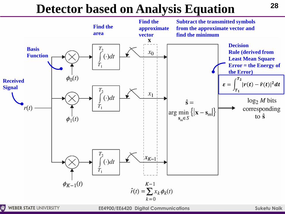
Comparison of Two Approaches
Impulse response of the matched filter=time-reversal of pulse-shaping filter*
*= this is generally true. For PAM, pulse shape=basis function. However, note that BPSK, QPSK, 16-QAM may not have identical pulse shape
and basis function. For example for QPSK, basis functions=p(t)*cos and -p(t)*sin; where p(t) is the pulse or the impulse response of the pulse-
shaping filter. We will cover pulse shapes, PAM, QAM in upcoming lectures.
Pulse or the impulse
response of the pulse-
shaping filter*

31
EE4900/EE6420 Digital Communications Suketu Naik
Summary: Demodulation (Detection)
It’s simple!
M-ary Demodulation (Detection):
1) Carrier signal is filtered, down-converted, filtered to baseband
signal
2) Now we reverse the process of modulation: pass it through
matched filter whose impulse response is the time-reversal of the
pulse shaping filter.
3) Output samples (x) from the matched filter are passed through
decision block which implements Least-Mean-Square error logic
4) Least-Mean-Square error logic:
1) x = we hope that these are the symbol amplitudes
2) a = we transmitted these symbol amplitudes=constellation
points
3) Take the differences x-a (Euclidean distance) and find the
minimum. This is the output or our best guess for what was
transmitted.

32
EE4900/EE6420 Digital Communications Suketu Naik
Examples

33
EE4900/EE6420 Digital Communications Suketu Naik
Example 5.1.1: Synthesis (Modulator)
Signal Space Projections
or Phase Diagram or
Constellation
Note that the points So and S1
are actual signals (symbols)
in time
0.5 1 0.5 1 0.5 1
0.5 1 0.5 1 0.5 1
basis function 1
(note: it can have different
amplitudes than 1 and -1)
basis function 2
K=2=two symbols
Two Orthonormal
Basis Functions
Coefficient chosen according
to the group of bits(=index)
Index Coeff
Symbols are constructed
from sum of the two basis
functions above
Coefficient chosen according
to the group of bits(=index)

34
EE4900/EE6420 Digital Communications Suketu Naik
Example 5.1.1: Analysis (Detector)How do we figure out what was transmitted given r(t)?
A: Find approximate vector [x0 x1]
The approximate vector
shown on the phase diagram
Received Signal r(t)
𝒙𝒌 = න𝑻𝟏
𝑻𝟐
𝒓 𝒕 ∅𝒌 𝒕 𝒅𝒕
Analysis Equation
Multiply r(t) with basis function,
then find the area (integral)
ො𝒓 𝒕 = 𝟐∅𝟎 𝒕 +𝟐
𝟑∅𝟏(𝒕)
ො𝒓(𝒕) =
𝒌=𝟎
𝑲−𝟏
𝒙𝒌∅𝒌(𝒕)

35
EE4900/EE6420 Digital Communications Suketu Naik
Example 5.1.1: Analysis (Detector)Transmitted signal s(t) Received signal r(t)
+0.5 1 0.5 1
2
4
2
Shape is changed and
Amplitude is changed. Why?
Approximate signal ො𝒓(𝒕)
0.5 1 0.5 1
1 1
-1
8/3=2.67
4/3=1.33
0.5 1
=
0.5 1
6
2
s(t)

36
EE4900/EE6420 Digital Communications Suketu Naik
Example 5.1.1: Analysis (Detector)Approximate vector
x=[2 2/3]
What was transmitted?
Sm=[6 2]
What did we determine as the transmitted signal?
Decision Rule:
|2-6|=4
|2/3-2|=1.33
Answer: Minimum of {4, 1.33}=1.33
What was transmitted? 0d (000b) or 1d (001b)or 2d (010b)?
0.5 1
6
2
s(t)