Embed Size (px)
Citation preview

Lecture 6
Angle Modulation and Demodulation

Agenda
Introduction to Angle Modulation and
Demodulation
Frequency and Phase Modulation
Angle Demodulation
FM Applications
Angle Modulation

Introduction
The other two parameters (frequency and phase) of the carrier sinusoid can be varied by the message signal m(t)
We will start by discussing the Frequency Modulation (FM)
Previously, it was thought that the bandwidth required by the FM is less than the one needed by the AM bandwidth
However, the bandwidth at FM is greater with several times than that of AM
Angle Modulation

Introduction
While AM signals carry a message with their varying amplitude, FM signals can vary instantaneous frequency in proportion to the modulating signal m(t)
The carrier frequency is changing continuously every instant
Instantaneous frequency Consider a general sinusoid
Conventional sinusoid
Angle Modulation
Introduction
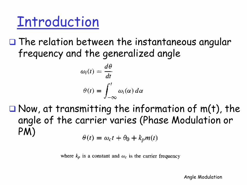
The relation between the instantaneous angular frequency and the generalized angle
Now, at transmitting the information of m(t), the angle of the carrier varies (Phase Modulation or PM)
Angle Modulation

Introduction
The resulting PM wave
In PM, the instantaneous angular frequency is given by
The instantaneous angular frequency varies linearly
with the derivative of the modulating signal (FM)
In FM, the instantaneous angular frequency is
Angle Modulation
Introduction
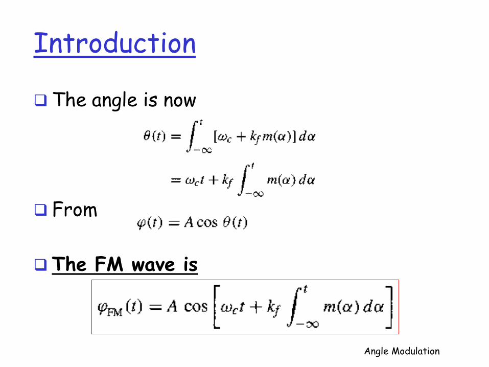
The angle is now
From
The FM wave is
Angle Modulation

Introduction
Angle Modulation

Introduction In both PM and FM, the angle of the
carrier is varied in proportion to some measure of m(t)
In PM, it is directly proportional to m(t)
In FM, it is proportional to the integral of m(t)
As shown in the figure in the previous slide, A frequency modulator can be directly used to
generate an FM signal or the message m(t) can be processed by a differentiator to generate PM signals
Angle Modulation

Introduction The generalized angle-modulated carrier can
be
The message m(t) can be recovered from
by passing it through a system with transfer function
Angle Modulation

Bandwidth of Angle-Modulated Waves
Unlike AM, angle modulation is nonlinear and no properties if Fourier transform can be directly applied for its bandwidth analysis
To determine the bandwidth of an FM wave
and define
Angle Modulation

Bandwidth of Angle-Modulated Waves
Such that its relationship to the FM signal is
Expanding the exponential in power series yields
and
Angle Modulation

Bandwidth of Angle-Modulated Waves
The modulated wave consists of an unmodulated carrier plus various amplitude-modulated terms
The signal a(t) is an integral of m(t)
If M(f) is bandlimited to B, A(f) is also bandlimited to B Integration is a linear operation equivalent to passing
a signal through a transfer function
The spectrum of is bandlimited to nB
Angle Modulation

Bandwidth of Angle-Modulated Waves
Although the bandwidth of an FM wave is theoretically infinite, for practical signals with bounded will remain finite
Angle Modulation

Narrowband Angle Modulation Approximation
Unlike AM, angle modulations are nonlinear
When
Then, the equation
becomes
Angle Modulation
Narrowband Angle Modulation Approximation
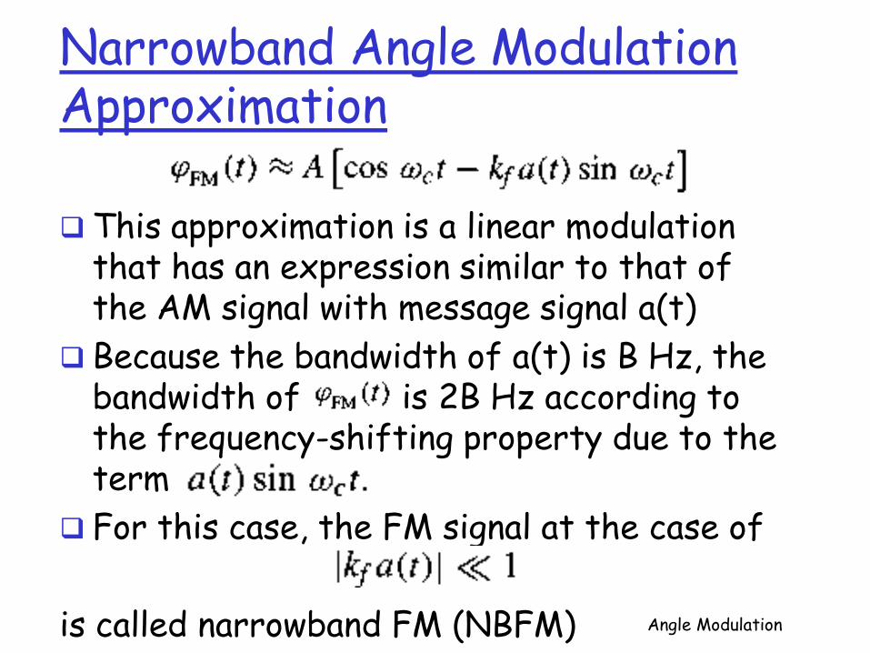
This approximation is a linear modulation that has an expression similar to that of the AM signal with message signal a(t)
Because the bandwidth of a(t) is B Hz, the bandwidth of is 2B Hz according to the frequency-shifting property due to the term
For this case, the FM signal at the case of
is called narrowband FM (NBFM) Angle Modulation
Wideband FM (WBFM) Bandwidth Analysis
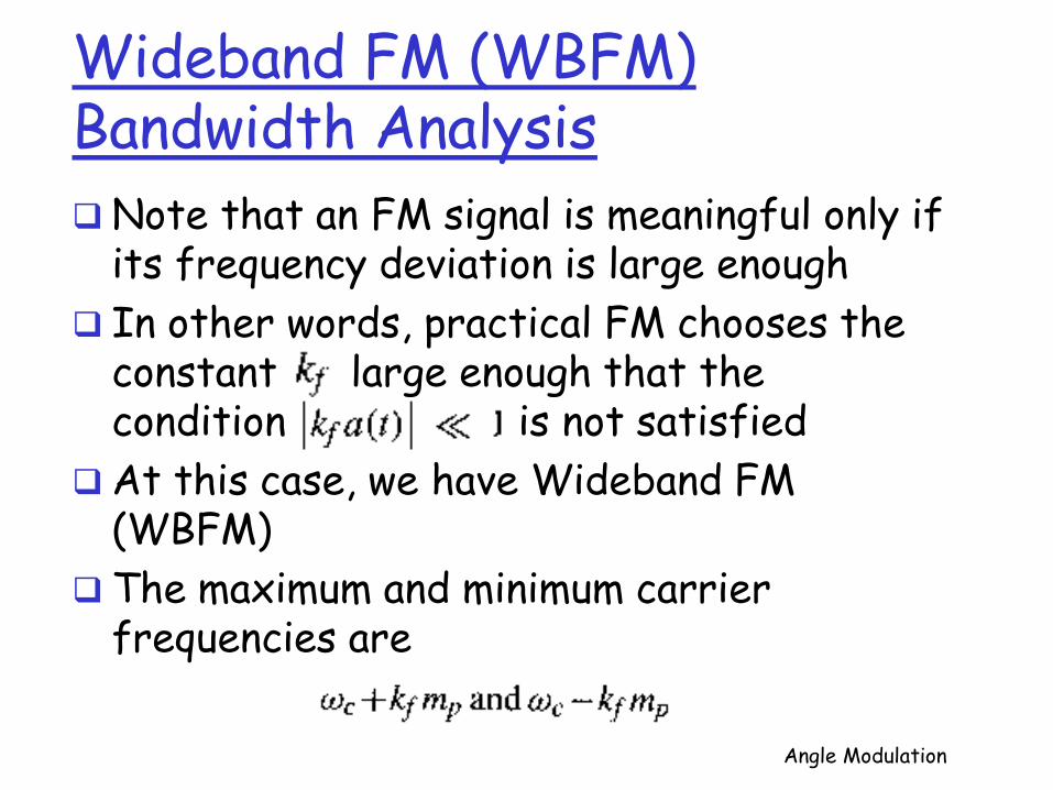
Note that an FM signal is meaningful only if its frequency deviation is large enough
In other words, practical FM chooses the constant large enough that the condition is not satisfied
At this case, we have Wideband FM (WBFM)
The maximum and minimum carrier frequencies are
Angle Modulation

Wideband FM (WBFM) Bandwidth Analysis
The peak frequency deviation from the carrier frequency
The estimated FM bandwidth
This estimated bandwidth is calculated based
on the staircase approximation of m(t)
This bandwidth is somewhat higher that the actual value Angle Modulation

Wideband FM (WBFM) Bandwidth Analysis
Better FM bandwidth approximation is between
In case of very small is very small that we have NBFM
So,
However, we showed previously that for NBFM, the FM bandwidth is approximately 2B Hz
Angle Modulation

Wideband FM (WBFM) Bandwidth Analysis
So, better estimate for bandwidth of FM
In case
We define a deviation ratio
The bandwidth of FM
β is called modulation index
Angle Modulation

Phase Modulation
All results derived for FM can be directly applied to PM
The instantaneous frequency
The peak frequency deviation
Angle Modulation

Phase Modulation
If we assume
Then
Angle Modulation

Notes In FM,
Depends only on the peak of m(t) not the spectrum
of m(t)
In PM,
Depends on the peak of
However, depends strongly on the spectral composition of m(t)
PM depends on the spectral shape of m(t) [not in FM]
So, for m(t) spectrum concentrated at lower frequencies, bandwidth of PM will be smaller than the one at case of m(t) spectrum concentrated at higher frequencies

Generating FM Waves
There are two ways of generating FM waves Indirect
• Narrowband FM generator
Direct • Voltage-controlled oscillator
Angle Modulation

Narrowband FM (NBFM) Generation
Indirect FM generators are used for generating wideband angle modulation signals
For NBFM and NBPM signals In case of and the modulated
signals can be approximated by
Both approximations are linear and similar to the expression of the AM wave
Angle Modulation

NBFM Generation The equations
Possible methods of generating narrowband FM and PM signals by using DSB-SC modulators
Angle Modulation

NBFM Generation
Because the approximation in
The NBFM generated by
has some distortion and amplitude variations

NBFM Generation
A nonlinear device designed to limit the amplitude of a bandpass signal can remove most of the distortion
Bandpass Limiter The amplitude variations of an angle-modulated
carrier can be eliminated by what is known as a bandpass limiter, consists of a hard limiter followed by a bandpass filter
Angle Modulation

NBFM Generation
Bandpass Limiter The input output characteristic of a hard limiter is
shown
The limiter output will be a square wave of unit amplitude regardless of the incoming sinusoidal amplitude
Angle Modulation

NBFM Generation
Angle-modulated sinusoidal input
Results in a constant amplitude angle-modulated square wave
Angle Modulation

Indirect Method of Armstrong
In this method, NBFM is generated as shown
Then converted to WBFM by using additional frequency multipliers
Angle Modulation

Indirect Method of Armstrong
A frequency multiplier can be realized by a nonlinear device followed by a bandpass filter
For a nonlinear device with output y(t) and input x(t)
If an FM signal passes through the device, the output signal will be
Angle Modulation

Indirect Method of Armstrong
Simplified commercial FM transmitter using Armstrong’s method
Angle Modulation

Direct Generation
In a voltage-controlled oscillator (VCO), the frequency is controlled by an external voltage
The oscillation frequency varies linearly with the control voltage
An FM wave by using the modulating signal m(t), as a control signal, can be generated
VCO can be built by varying one of the reactive parameters (C or L) of the resonant circuit
Angle Modulation

Features of Angle Modulation The transmission bandwidth of AM systems
cannot be changed
In angle modulation, the transmission bandwidth can be adjusted by adjusting ∆f
AM systems do not have the feature of exchanging signal power for transmission bandwidth
For angle-modulated systems, the SNR is roughly proportional to the square of the transmission bandwidth
Angle Modulation

Demodulation of FM Signals The information in an FM signal
resides in the instantaneous frequency
Frequency-selective network with a transfer function of the form
Over the FM band would yield an output proportional to the instantaneous frequency
Angle Demodulation

Demodulation of FM Signals FM demodulator frequency response
Output of the differentiator to the input FM wave
Angle Demodulation

Demodulation of FM Signals FM demodulation by direct differentiation
Ideal differentiator with transfer function is j2πf
The output if we apply to the ideal differentiator
.

Demodulation of FM Signals Both the amplitude and the frequency of the
signal are modulated
Because , we have for all t
Then, m(t) can be obtained by envelope detection
The amplitude A of the carrier should be constant
Channel noise and fading cause A to vary

Demodulation of FM Signals Practical Frequency Demodulators
The differentiator is only one way to convert frequency variation of FM signals into amplitude variation [envelope detectors]
Another method for detection using Operational amplifier differentiator
The role of the differentiator can be replaced by any linear system (frequency response contains a linear segment of positive slope) [slope detection]

Demodulation of FM Signals Practical Frequency Demodulators
One simple device for FM demodulation is an RC high-pass filter
The RC frequency response
If the parameter RC << that The RC filter approximates a differentiator

Demodulation of FM Signals FM Demodulation via Phase Locked Loop (PLL)
Voltage Controlled Oscillator
Angle Demodulation

Demodulation of FM Signals FM Demodulation via Phase Locked Loop (PLL)
Consider a PLL with input signal
and output error signal
When the input signal is an FM signal
The loop filter output signal
If the incoming signal is a PM wave, then
Angle Demodulation

Effects of Nonlinear Distortion and Interference
Immunity of Angle Modulation to Nonlinearities Very useful feature of angle modulation is its constant
amplitude, which makes it less susceptible to nonlinearities
Amplifier with second order nonlinear distortion
Clearly, the first term is the desired signal amplification term, the remaining terms are the unwanted nonlinear distortion

Effects of Nonlinear Distortion and Interference
Immunity of Angle Modulation to Nonlinearities For the angle modulated signal
The nonideal system output
A bandpass filter centered at with bandwidth equaling to can extract the desired FM signal component without any distortion
For a DSB-SC signal passes through a nonlinearity , the output is

Effects of Nonlinear Distortion and Interference
Interference Effect Angle modulation is also less vulnerable than AM to small-
signal interference from adjacent channels
Let us consider the interference of an unmodulated carrier with another sinusoid
The received signal
where

Effects of Nonlinear Distortion and Interference
Interference Effect When the interfering signal is small in comparison to the
carrier
then
The output
The interference output is inversely proportional to the carrier amplitude A
The larger A, the smaller interference effect in FM

Effects of Nonlinear Distortion and Interference
Interference due to Channel Noise The channel noise acts as interference in an angle-
modulated signal
We will consider the most common form of noise, white noise, which has a constant power spectral density
Such noise may be considered as a sum of sinusoids of all frequencies in the band
All components have the same amplitudes (uniform density)
This means that the interference I is constant for all frequencies

Effects of Nonlinear Distortion and Interference
Interference due to Channel Noise The amplitude spectrum of the interference at the
receiver output is shown
Effect of interference in PM, FM, and FM with preemphasis-deemphasis (PDE)

Effects of Nonlinear Distortion and Interference
Interference due to Channel Noise
Preemphasis and Deemphasis in FM Broadcasting In FM, interference increases linearly with frequency
The noise power in the receiver output is concentrated at higher frequencies
To consider this issue • At the transmitter, the weaker high frequency components are
boosted before modulation
• At the receiver, attenuating the higher frequency components

Effects of Nonlinear Distortion and Interference
Interference due to Channel Noise
Preemphasis and Deemphasis in FM Broadcasting

Effects of Nonlinear Distortion and Interference
Interference due to Channel Noise
Preemphasis and Deemphasis Filters Assignment
• Prepare a report about those filters discussing their comprising components and their works
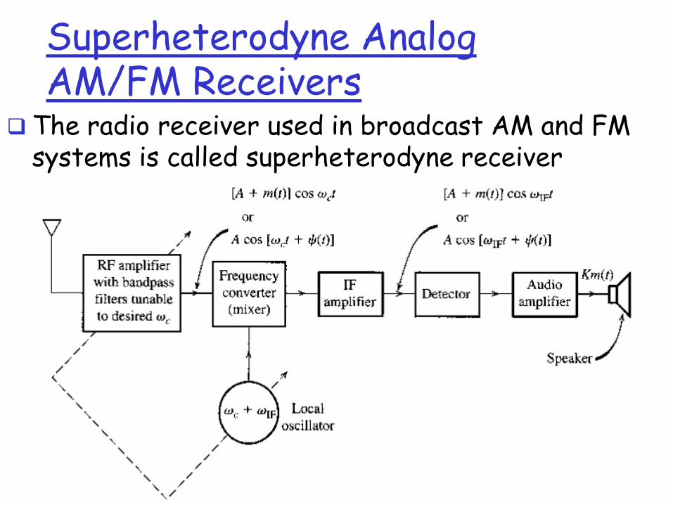
Superheterodyne Analog AM/FM Receivers
The radio receiver used in broadcast AM and FM systems is called superheterodyne receiver

Superheterodyne Analog AM/FM Receivers
It consists of
an RF (radio-frequency) section
• Tunable filter and an amplifier
a frequency converter or mixer
• Translates the carrier from to a fixed IF frequency
An intermediate-frequency (IF) amplifier
An envelope detector
An audio amplifier

Superheterodyne Analog AM/FM Receivers
The importance of the superheterodyne receiver
Used in radio and television broadcasting
Adequate selectivity of frequencies
Accommodate many carrier frequencies

FM Broadcasting System
FM Transmitter
The FCC has assigned a frequency range of 88 to 108
MHz for FM broadcasting with a separation of 200 KHz between adjacent stations

FM Broadcasting System
Spectrum of a baseband stereo signal
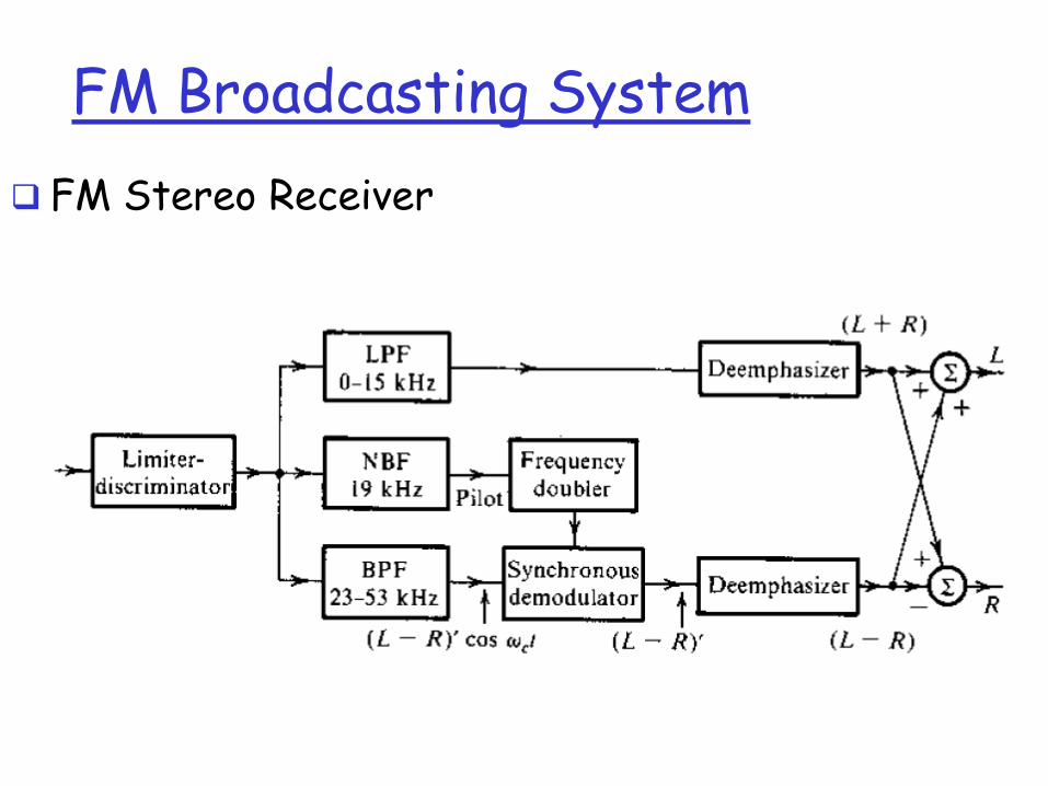
FM Broadcasting System
FM Stereo Receiver

Lecture Summary
Covered material Introduction to Angle Modulation and Demodulation
Frequency and Phase Modulation Angle Demodulation FM Applications
Material to be covered next lecture Performance Study of Angle Modulation in the
Existence of Noise
Angle Modulation