Embed Size (px)
Citation preview

Stephan Henzler Mixed-Signal-Electronics 2011/12
Mixed-Signal-Electronics
PD Dr.-Ing. Stephan Henzler
1

Stephan Henzler Mixed-Signal-Electronics 2011/12
Binary Number Representation
2
# #
normalized
Sign
magnitude
1‘s
complement
2‘s
complement
Offset
binary
+7 +7/8 0111 0111 0111 1111
+6 +6/8 0110 0110 0110 1110
+5 +5/8 0101 0101 0101 1101
+4 +4/8 0100 0100 0100 1100
+3 +3/8 0011 0011 0011 1011
+2 +2/8 0010 0010 0010 1010
+1 +1/8 0001 0001 0001 1001
+0 0 0000 0000 0000 1000
-0 0 1000 1111
-1 -1/8 1001 1110 1111 0111
-2 -2/8 1010 1101 1110 0110
-3 -3/8 1011 1100 1101 0101
-4 -4/8 1100 1011 1100 0100
-5 -5/8 1101 1010 1011 0011
-6 -6/8 1110 1001 1010 0010
-7 -7/8 1111 1000 1001 0001
-8 -8/8 1000 0000
Stephan Henzler Mixed-Signal-Electronics 2011/12
Nyquist Rate
Digital-to-Analog Converters
3
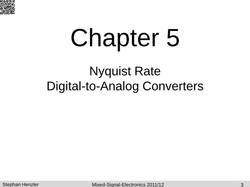
Chapter 5
Stephan Henzler Mixed-Signal-Electronics 2011/12
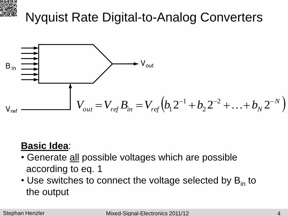
Nyquist Rate Digital-to-Analog Converters
4
Basic Idea:
• Generate all possible voltages which are possible
according to eq. 1
• Use switches to connect the voltage selected by Bin to
the output
N
Nrefinrefout bbbVBVV 222 2
2
1
1

Stephan Henzler Mixed-Signal-Electronics 2011/12
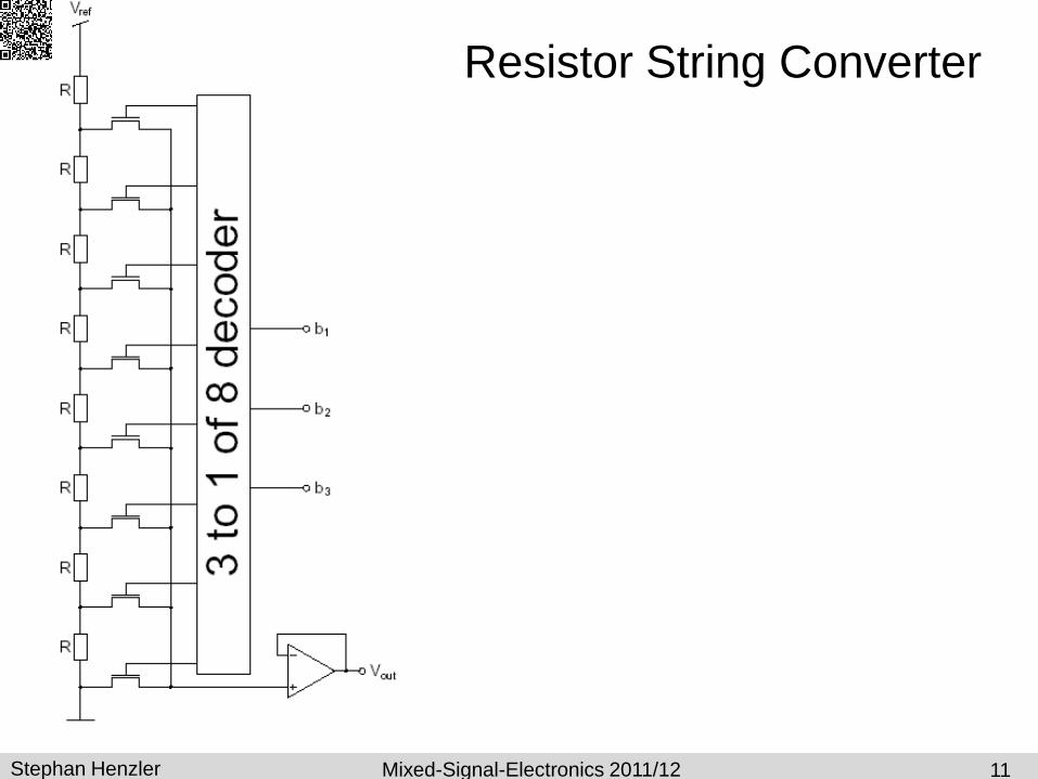
3-Bit Resistor String Converter
Generate all possible voltages with
resistive voltage divider
Switches = NMOS transistors
Transmission gates enable
– higher voltage range
– but higher parasitic cap, area
(layout more complicated)
Buffer experiences high input
voltage variation
Slow due to buffer and analog mux
How fast does the DAC settle
5
str
ictl
y m
on
oto
nic
voltage follower
bu
s
max value

Stephan Henzler Mixed-Signal-Electronics 2011/12
Elmore Delay
6
Prerequisites:
– one input only
– caps between network node and ground only
– no resistive loops
W. C. Elmore, The Transient Response of Damped Linear Networks with Particular Regard to Wideband Amplifiers, Journal of Applied Physics, 1948.
Stephan Henzler Mixed-Signal-Electronics 2011/12
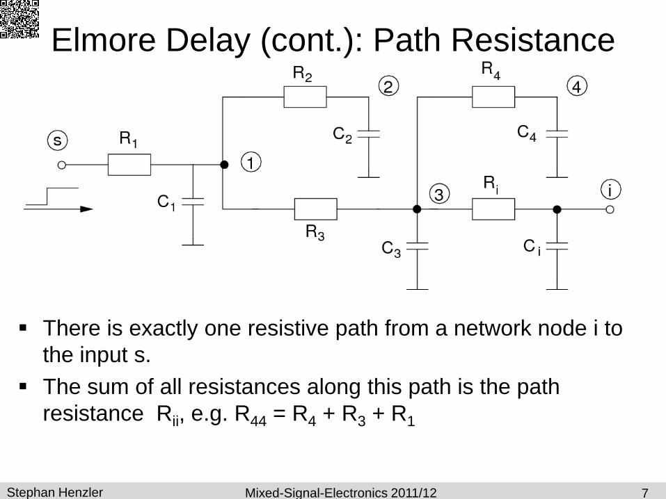
Elmore Delay (cont.): Path Resistance
7
There is exactly one resistive path from a network node i to
the input s.
The sum of all resistances along this path is the path
resistance Rii, e.g. R44 = R4 + R3 + R1

Stephan Henzler Mixed-Signal-Electronics 2011/12
Elmore Delay: Shared Path Resistance
The shared path resistance Rik is the sum of all resistances
along the joint sub-path of the two paths s i and s k.
Example: Ri4 = R1 + R3
8

Stephan Henzler Mixed-Signal-Electronics 2011/12
SS 2008
9
Elmore Delay (cont): Delay Approximation
Elmore delay:
First order approximation of the delay after which a voltage step at the input s can be observed at the output i.

Stephan Henzler Mixed-Signal-Electronics 2011/12
SS 2008
10
Elmore Delay (cont): Delay Approximation
Elmore delay:
Useful for
– Estimation of wire delay
– Estimation of DAC settling time
– …
Stephan Henzler Mixed-Signal-Electronics 2011/12
Resistor String Converter
11

Stephan Henzler Mixed-Signal-Electronics 2011/12 12
Resistor String Converter
(with pass-gate decoder)
Stephan Henzler Mixed-Signal-Electronics 2011/12
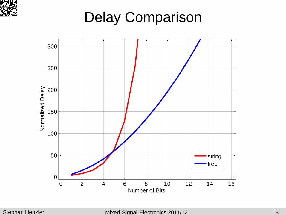
Delay Comparison
13
0 2 4 6 8 10 12 14 160
50
100
150
200
250
300
Number of Bits
No
rma
lize
d D
ela
y
string
tree
Stephan Henzler Mixed-Signal-Electronics 2011/12
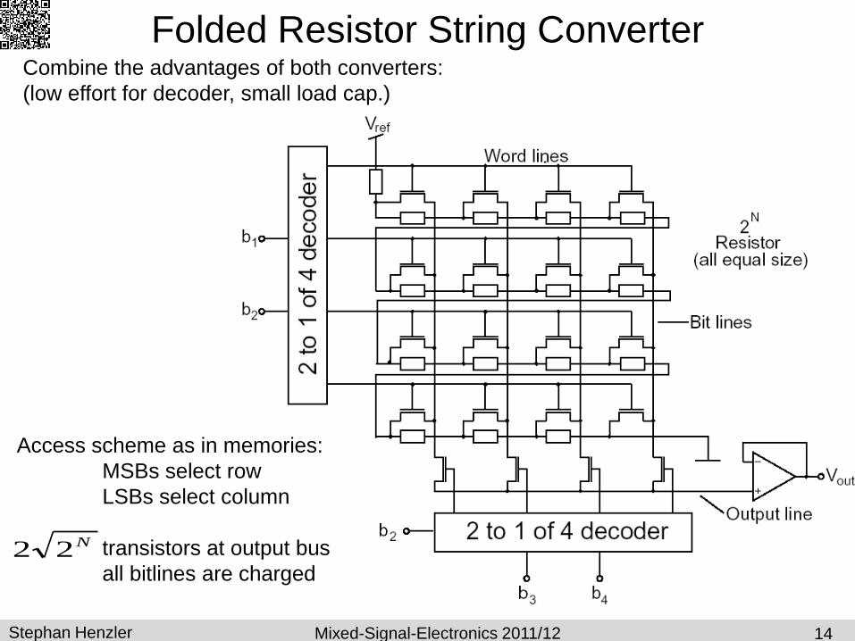
Folded Resistor String Converter
14
Combine the advantages of both converters:
(low effort for decoder, small load cap.)
Access scheme as in memories:
MSBs select row
LSBs select column
transistors at output bus
all bitlines are charged
N22

Stephan Henzler Mixed-Signal-Electronics 2011/12
Multi-Stage
Resistor String Converter
Subdivde voltage range in
coarse sub-intervals first
Copy the respective voltage
interval
Fine interpolation of the
copied interval
15
• if opamps match the converter is monotonic
• less resistors
• reduced area and power

Stephan Henzler Mixed-Signal-Electronics 2011/12
Binary Weighted Current Mode Converters
16
Until now: All possible voltages are generated,
1 out of 2N voltages is copied to the output
Now:
• Current mode, i.e. currents are generated, superposed
and then converted into the output voltage
• Input word is already binary generated binary weighted
currents and superpose them into a current that corresponds
to the input word.
IbIbIbIbIF 481
341
221
1
1
min
max 2 N
I
I
scale switches
Stephan Henzler Mixed-Signal-Electronics 2011/12
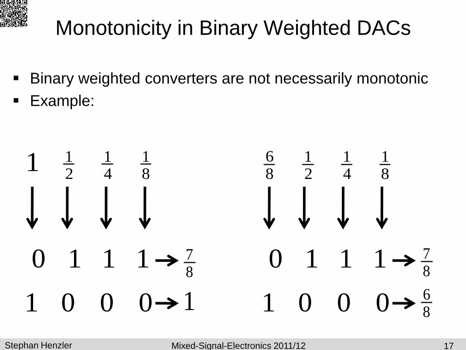
Monotonicity in Binary Weighted DACs
Binary weighted converters are not necessarily monotonic
Example:
17
81
41
211
1110
0001 1
87
81
41
21
86
1110
0001 86
87
Stephan Henzler Mixed-Signal-Electronics 2011/12
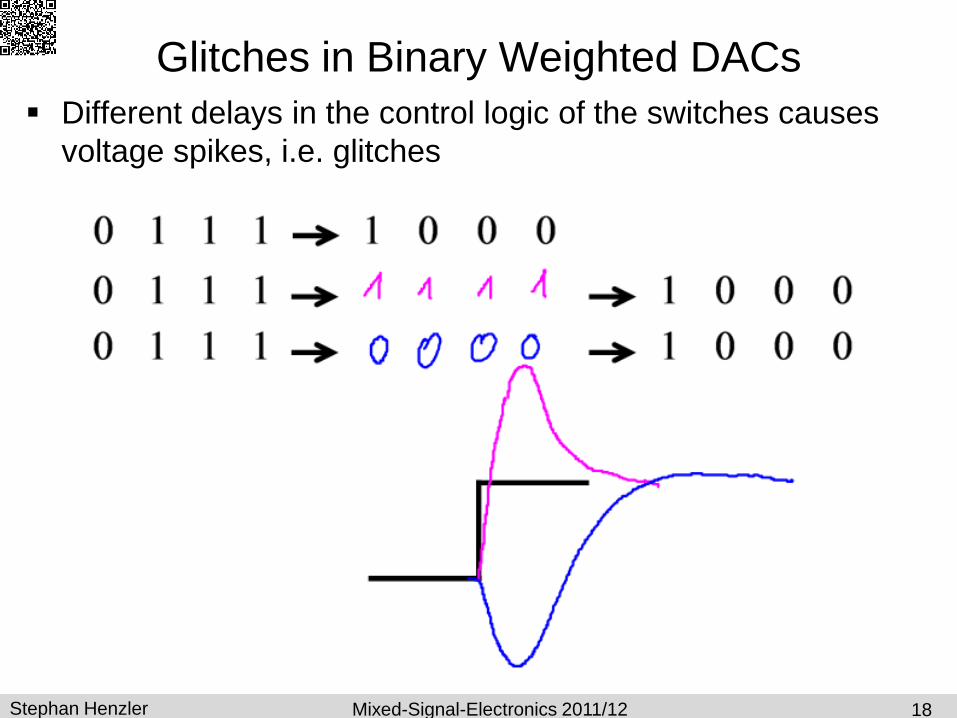
Glitches in Binary Weighted DACs
Different delays in the control logic of the switches causes
voltage spikes, i.e. glitches
18
1110 0001
1110 1111
1110 0000
0001
0001
Stephan Henzler Mixed-Signal-Electronics 2011/12
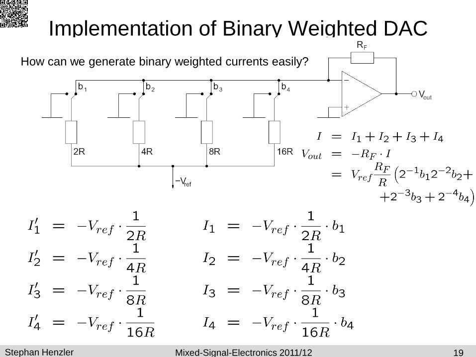
Implementation of Binary Weighted DAC
19
How can we generate binary weighted currents easily?
Stephan Henzler Mixed-Signal-Electronics 2011/12
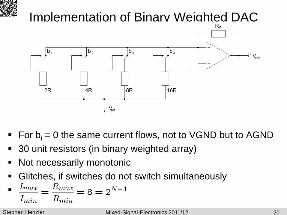
Implementation of Binary Weighted DAC
For bi = 0 the same current flows, not to VGND but to AGND
30 unit resistors (in binary weighted array)
Not necessarily monotonic
Glitches, if switches do not switch simultaneously
20
Stephan Henzler Mixed-Signal-Electronics 2011/12
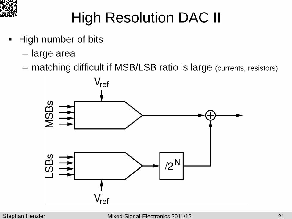
High Resolution DAC II
High number of bits
– large area
– matching difficult if MSB/LSB ratio is large (currents, resistors)
21

Stephan Henzler Mixed-Signal-Electronics 2011/12
High Resolution DAC
High number of bits
– large area
– matching difficult if MSB/LSB ratio is large (currents, resistors)
22

Stephan Henzler Mixed-Signal-Electronics 2011/12
Implementation of Binary Weighted DAC
(with improved resistor ratio)
23

Stephan Henzler Mixed-Signal-Electronics 2011/12
Implementation of Binary Weighted DAC
(with improved resistor ratio)
(reduced)
19 unit resistors 24 24
Stephan Henzler Mixed-Signal-Electronics 2011/12
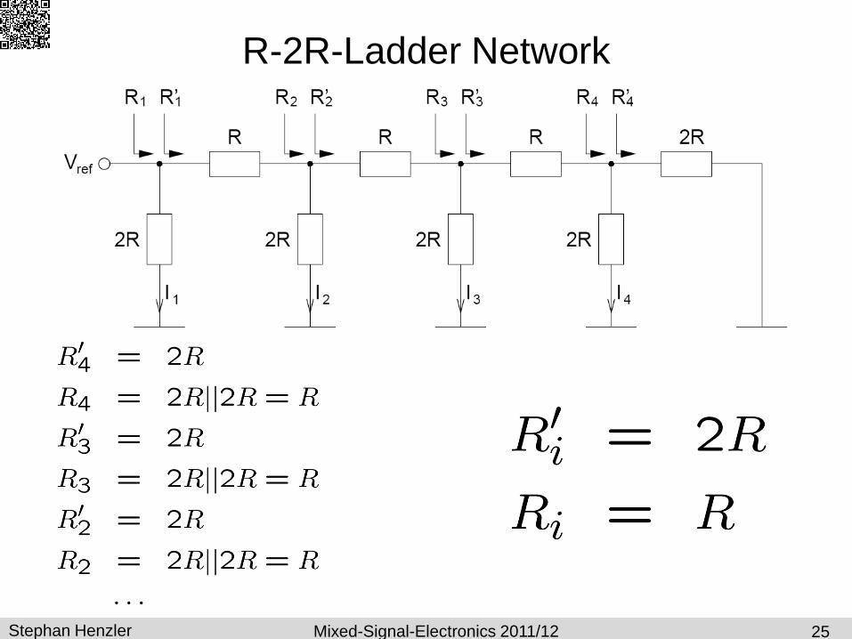
R-2R-Ladder Network
25
Stephan Henzler Mixed-Signal-Electronics 2011/12
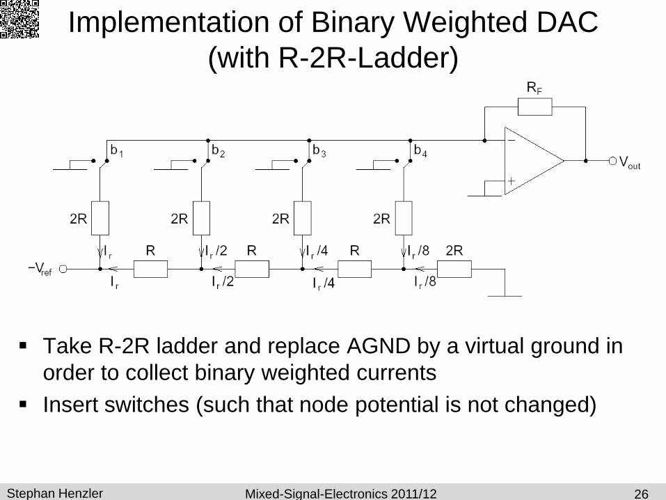
Implementation of Binary Weighted DAC
(with R-2R-Ladder)
Take R-2R ladder and replace AGND by a virtual ground in
order to collect binary weighted currents
Insert switches (such that node potential is not changed)
26

Stephan Henzler Mixed-Signal-Electronics 2011/12
Implementation of Binary Weighted DAC
(with R-2R-current divider)
R-2R ladder as current divider
27

Stephan Henzler Mixed-Signal-Electronics 2011/12
Switched Capacitor Amplifier
(without output reset)
28 28

Stephan Henzler Mixed-Signal-Electronics 2011/12
SC-Amplifier with Controllable Capacitors
Various variants possible
Gain is altered according to binary input
multiplying DAC (M-DAC)
29
Stephan Henzler Mixed-Signal-Electronics 2011/12
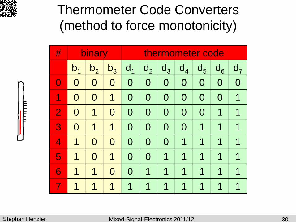
Thermometer Code Converters
(method to force monotonicity)
30
# binary thermometer code
b1 b2 b3 d1 d2 d3 d4 d5 d6 d7
0 0 0 0 0 0 0 0 0 0 0
1 0 0 1 0 0 0 0 0 0 1
2 0 1 0 0 0 0 0 0 1 1
3 0 1 1 0 0 0 0 1 1 1
4 1 0 0 0 0 0 1 1 1 1
5 1 0 1 0 0 1 1 1 1 1
6 1 1 0 0 1 1 1 1 1 1
7 1 1 1 1 1 1 1 1 1 1

Stephan Henzler Mixed-Signal-Electronics 2011/12
Thermometer Code Converters
(method to force monotonicity)
31
Stephan Henzler Mixed-Signal-Electronics 2011/12
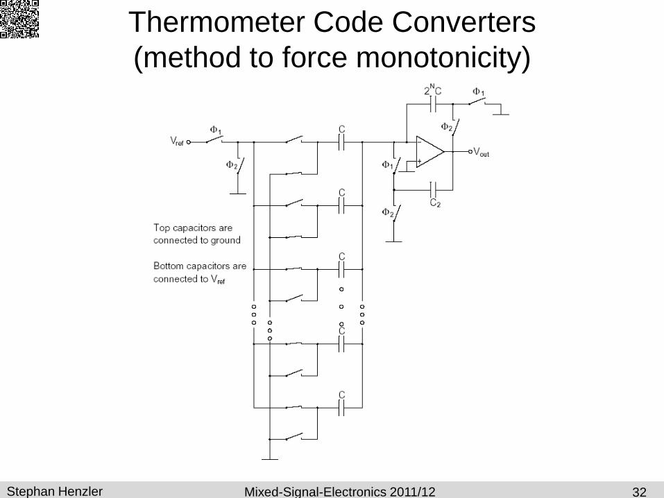
Thermometer Code Converters
(method to force monotonicity)
32
Stephan Henzler Mixed-Signal-Electronics 2011/12
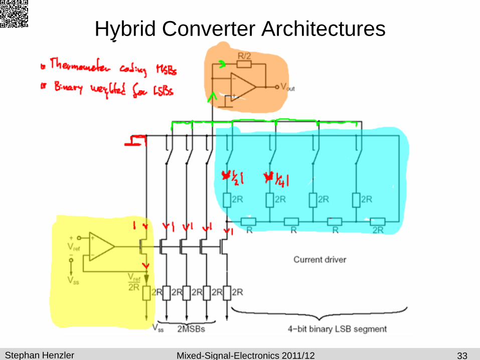
Hybrid Converter Architectures
33

Stephan Henzler Advanced Integrated Circuit Design 2011/12
Differential Current Steering DAC
34
b1 b2 b3 I+ I- Vo
0 0 0 0 I 7/4 I -7/8 RI
0 0 1 1/4 I 6/4 I -5/8 RI
0 1 0 2/4 I 5/4 I -3/8 RI
0 1 1 3/4 I 4/4 I -1/8 RI
1 0 0 4/4 I 3/4 I 1/8 RI
1 0 1 5/4 I 2/4 I 3/8 RI
1 1 0 6/4 I 1/4 I 5/8 RI
1 1 1 7/4 I 0 I 7/8 RI

Stephan Henzler Advanced Integrated Circuit Design 2011/12
Charge Scaling DAC
Compatibel with switched capacitor circuits
Principle: Divide charge binarily
All caps discharged during 1 (reset phase, no valid output)
35