Embed Size (px)
Citation preview

Modelling of Steam Turbine and its Governing System
Dr M S R Murty
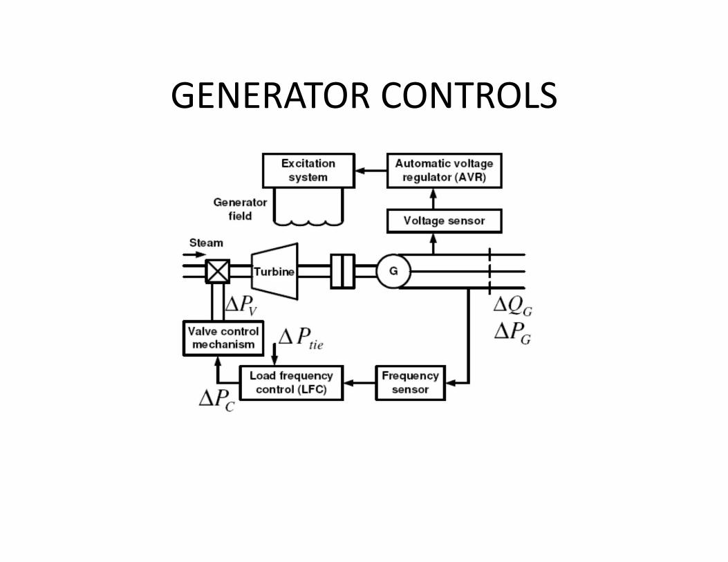
GENERATOR CONTROLS

Grid
Reference
ST : steam turbineG : generator
SV : stop valve
CV
SVSteam
Speed
Power
GOVERNINGSYSTEM G
ST
CV contr. valve valve
Fig. 1 STEAM TURBINE GOVERNING SCHEME

SPEED
+
Valve
Position
SET
POINT -
Mechanical
Power
+GOVERNOR TURBINE ROTOR
INERTIA
Fig 2 GOVERNING SYSTEM FUNCTIONAL BLOCK DIAGRAM

Governing Control system
• Speed Sensing :Mechanical (Fly ball type), Hydraulic (Pump), Electric (toothed Wheel pick up)
• MW Transducer for Power• Processing : Hydro‐mechanical, Electro‐hydraulic, Digital Electro‐hydraulic
• Amplification: Hydraulic amplifiers in various stages
• Actuation: Hydraulic Servomotor

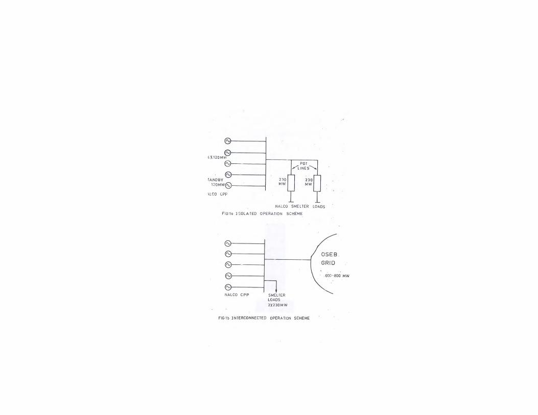
TG Unit Operating Modes:Isolated : S Open : Speed changes when gov valve is adjusted
Interconnected : S Closed or grid connected: Speed is unaffected
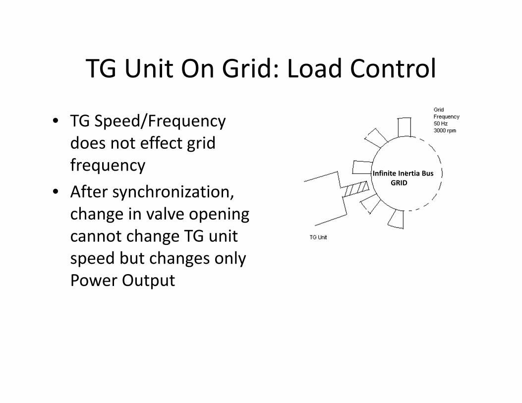
TG Unit On Grid: Load Control
• TG Speed/Frequency does not effect grid frequency
• After synchronization, change in valve opening cannot change TG unit speed but changes only Power Output
Infinite Inertia BusGRID
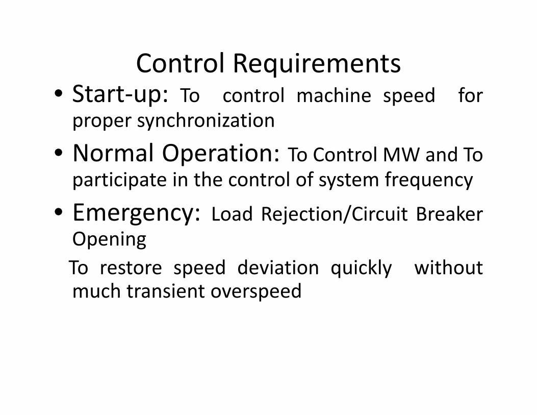
Control Requirements• Start‐up: To control machine speed forproper synchronization
• Normal Operation: To Control MW and Toparticipate in the control of system frequency
• Emergency: Load Rejection/Circuit BreakerOpeningTo restore speed deviation quickly withoutmuch transient overspeed

Governing system: Technology
• Mechanical Hydraulic Control (MHC)• Electro‐ Hydraulic Control (EHC)Sensing, Processing, primary amplification using electronic circuitryTransistor version (BHEL/ KWU Siemens Iskamatic modules)
• Digital Electro‐ Hydraulic Control (DEHC)Microprocessor based
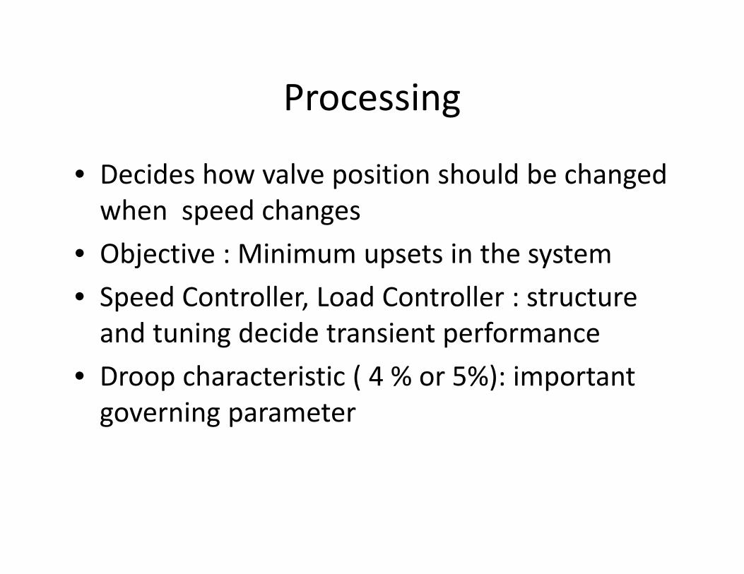
Processing
• Decides how valve position should be changed when speed changes
• Objective : Minimum upsets in the system• Speed Controller, Load Controller : structure and tuning decide transient performance
• Droop characteristic ( 4 % or 5%): important governing parameter

Electronic Controller Features
• Separation of Speed Control and Load (Power) Control functions with separate processing philosophy
• Speed Controller: Proportional‐ Derivative action: Anticipatory Control
• Load Controller: Proportional‐ Integral action• Interaction with ATRS and TSE

Simple Speed governing system
/Gate
Command
GateOil
ServomotorSENSING
PROCESSING AMPLIFICATION AND ACTUATION
SETPOINT

Steam
· Actuation of Valve (Servomotor)
· Hydraulic Amplification
Speed & MW
· PrimaryAmplification
· Sensing
· Processing
Electro-hydraulicConverter
ControlValve
EH
HYDRAULICPART
ST
G
ELECTRONICPART
Fig 3 ELECTRO – HYDRAULIC GOVERNOR SCHEME

VALVEOPENINGCOMMAND
––
Load
Speed
+
+LoadRef.
SpeedRef.
SPEEDCONTROLLER
(PDP)
LOADCONTROLLER
( P I )
SELECTIONLOGIC
(MIN – MAX)
Fig 4 SPEED CONTROLLER AND LOAD CONTROLLER IN EHG

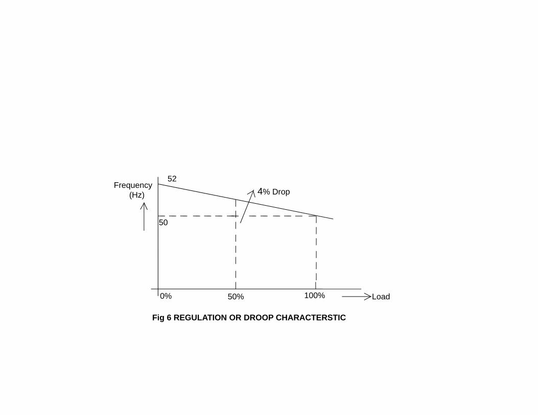
Droop Characteristic
Speed Change
Turbine Power Change
= (Load)
Valve Opening Change
Steam Flow Change
Load %
Speed Or Frequency
104 %
100 %
0 50 100
52 Hz
50 Hz
Frequency(Hz)
50
524% Drop
Load0% 50% 100%
Fig 6 REGULATION OR DROOP CHARACTERSTIC
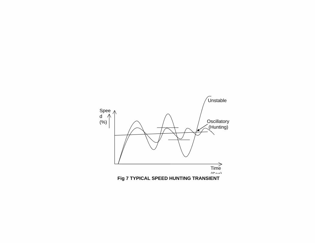
Time (Sec)
Speed(%)
Unstable
Oscillatory (Hunting)
Fig 7 TYPICAL SPEED HUNTING TRANSIENT
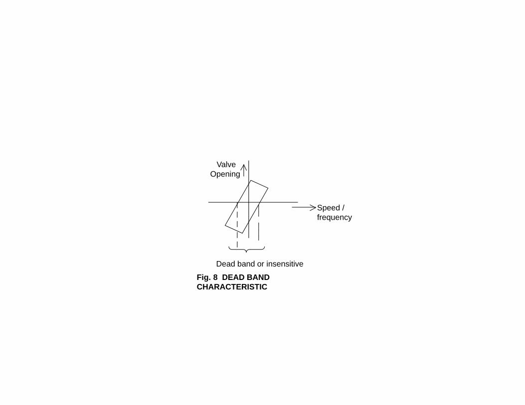
ValveOpening
Dead band or insensitive zone
Speed / frequency
Fig. 8 DEAD BAND CHARACTERISTIC

STEAM TURBINE SCHEME WITH HP AND IP CONTROLS
Reheater
IPCV
HPCVSteam
Condenser
LPTHPT
IPT G
R H
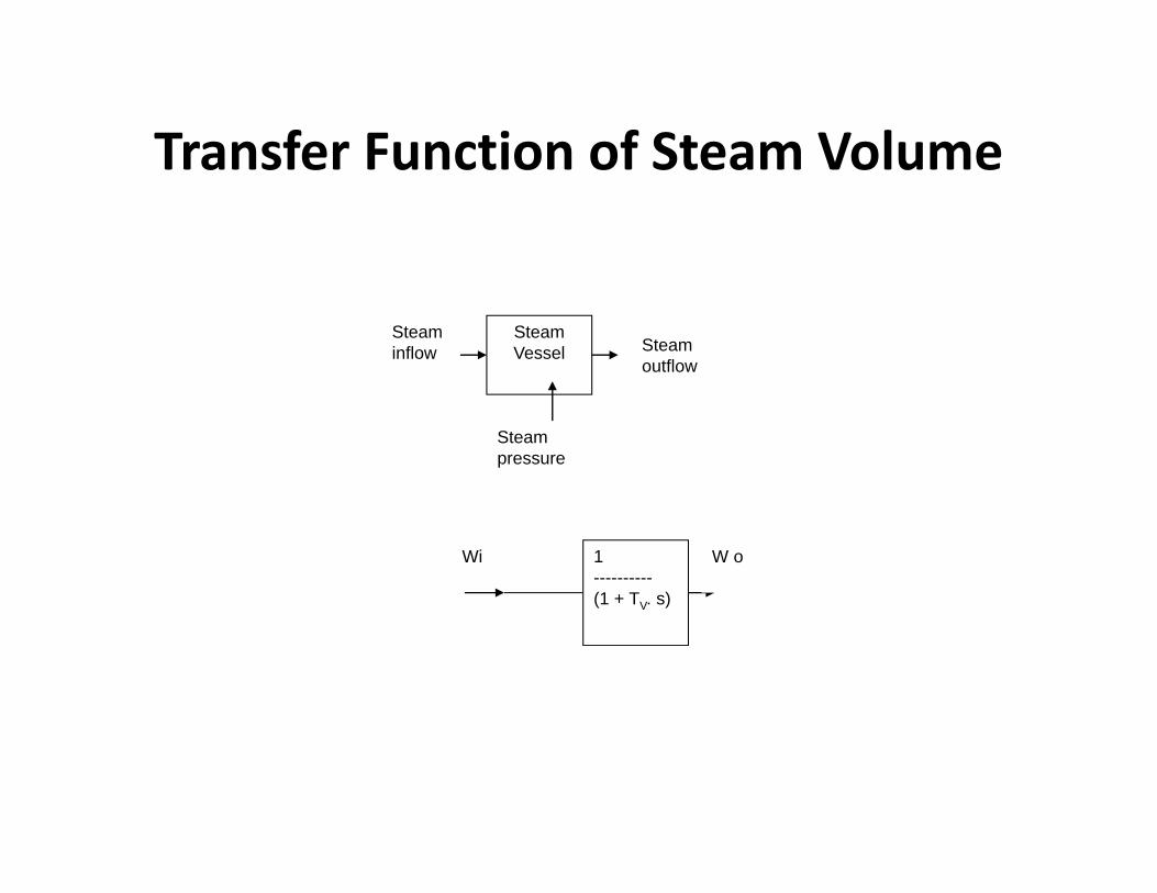
Transfer Function of Steam Volume
Steam Vessel
Steam inflow Steam
outflow
Steam pressure
1----------(1 + TV. s)
Wi W o

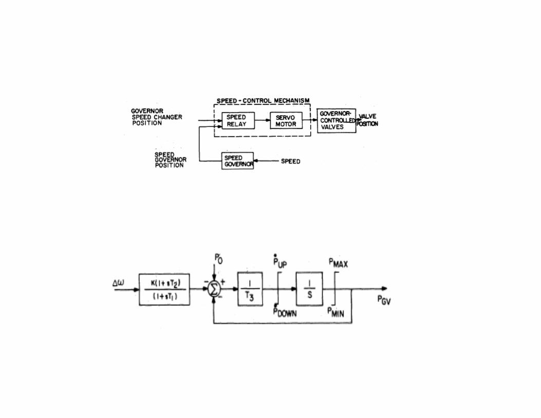
Functional block diagram of turbine governing system

TURBINE CONTROLLER
29Feed forward provision
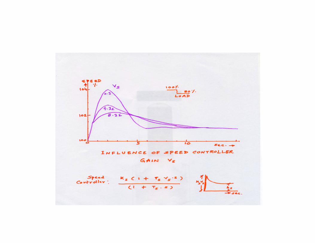
KSVSSpeed Controller: Proportional Derivative
Load Controller : Proportional Integral
Load
Load Ref
SpeedRef SPEED
CONTROLLER
LOADCONTROLLER
SELECTIONLOGIC
EH
To Hyd.Amplifier
speed
Ks(1+VsTs.S)(1 + Ts . S)droop
KPL + 1TILS
KS

PI
t
Output(Y)
t
PDP
K
Output(Y)
Speed Controller Load Controller
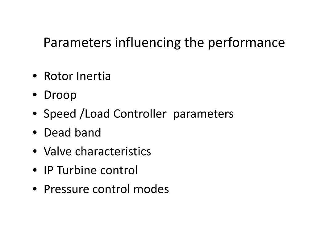
Parameters influencing the performance
• Rotor Inertia• Droop• Speed /Load Controller parameters• Dead band• Valve characteristics• IP Turbine control• Pressure control modes
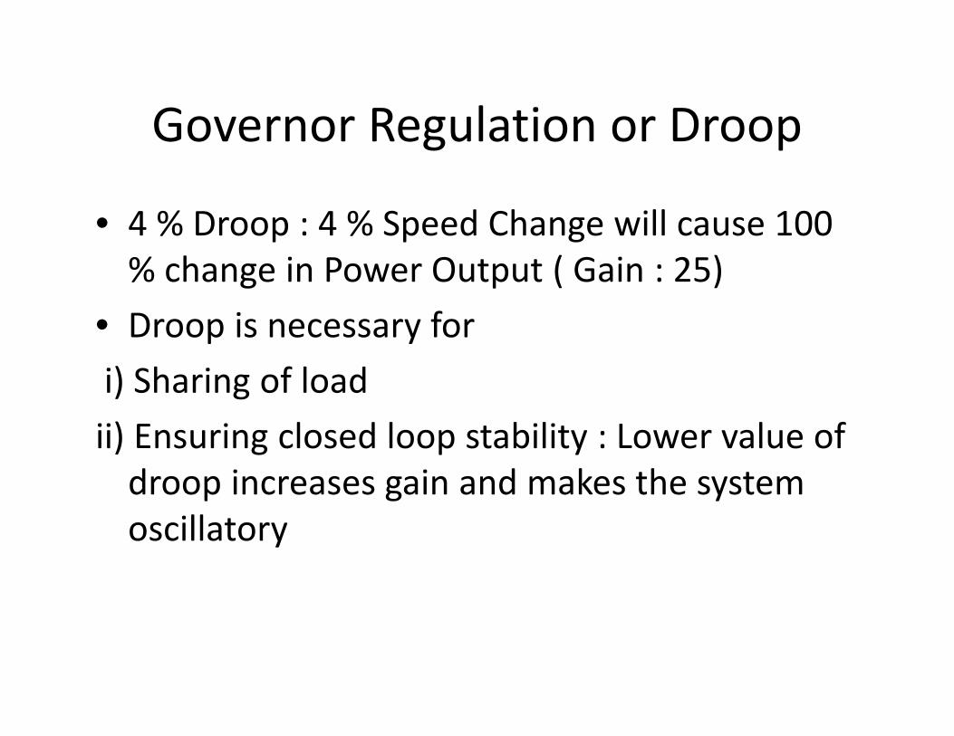
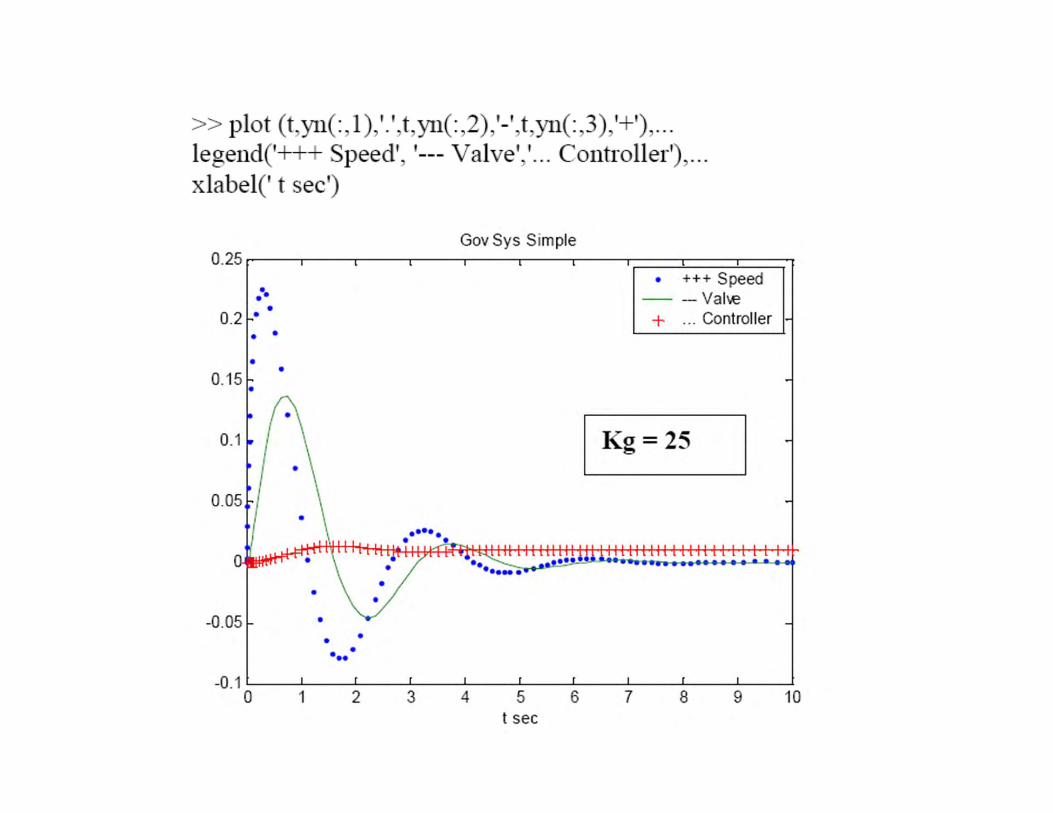
Governor Regulation or Droop
• 4 % Droop : 4 % Speed Change will cause 100 % change in Power Output ( Gain : 25)
• Droop is necessary fori) Sharing of loadii) Ensuring closed loop stability : Lower value of droop increases gain and makes the system oscillatory

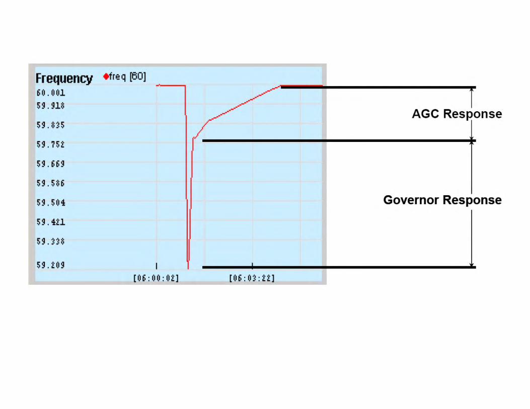
Governing System Response
• Response times are important : delay in correction can cause transient speed rise high and trip the turbine
• Stability of governing system depends on processing algorithm ( PI, PID , PDP etc.,) and on system parameters & time constants
Performance specifications: Load Rejection
• Rejection to zero load from any load• Speed shall be returned to the set point as may be modified by speed droop or regulation
• No more than one under speed deviation exceeding 5 %
• No more than one over speed deviation exceeding 5 % after initial over speed deviation
Performance specifications: Sustained conditions
• Steady state governing speed band: Not more than 0.3 % ( at no load or any load). Also called speed stability index.
• Steady state governing load band: Not more than 0.4 % ( at 5 % speed droop) Also called power stability index.

Stability Index: Degree of stability
• Judged by the magnitude of sustained oscillations of speed and power output from the turbine that are produced by the governor system
• Stability index illustrates the regulating performance for the governor and turbine
• Governor Deadband illustrates the performance for the governor alone

Load Rejection
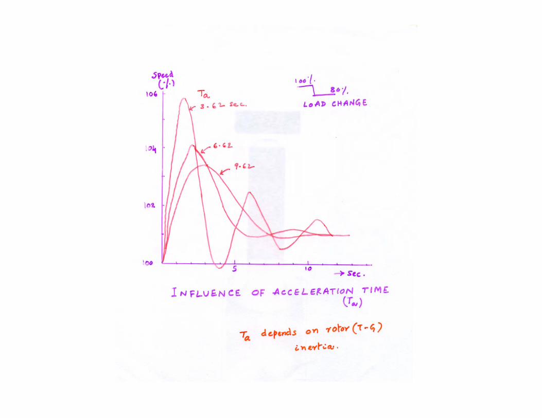
• Governing System Performance can be judged by full load rejection behavior : Transient Speed Rise (TSR), hunting
• Emergency Governor should not get activated• Influencing parameters : Rotor Acceleration Time ( Ta), Droop, Speed Controller gains, Incremental droop
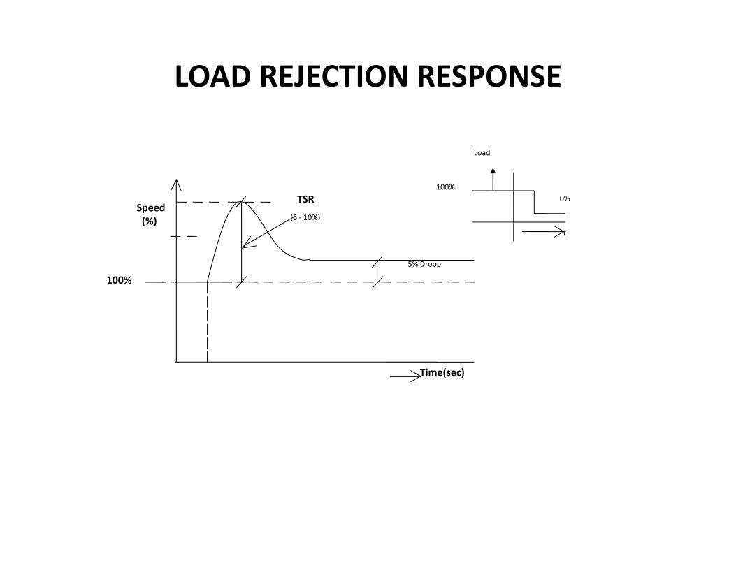
LOAD REJECTION RESPONSE
Load
100%
Time(sec)
t
100%0%
Speed(%)
TSR(6 ‐ 10%)
5% Droop

3
FW
SH1
QDRUM
WW
BOILER
SH2
G
Q
150 at a 540ºC
HTP
IPT
COND
RH
.
.
.
Flue Gas
Fuel
Air
DESH
Interaction with Boiler Controls
GOVERNOR
Master PressureControl
Drum Levelcontrol
TemperatureControl
Spray

ExtractionSteamPressure
STEAM
CONDENSER
LPCVLOAD
SPEED
HPT
LPT G
GOV,SYSTEM
HPCV
TO PROCESS
EXTRACTION TURBINE CONTROL SCHEME
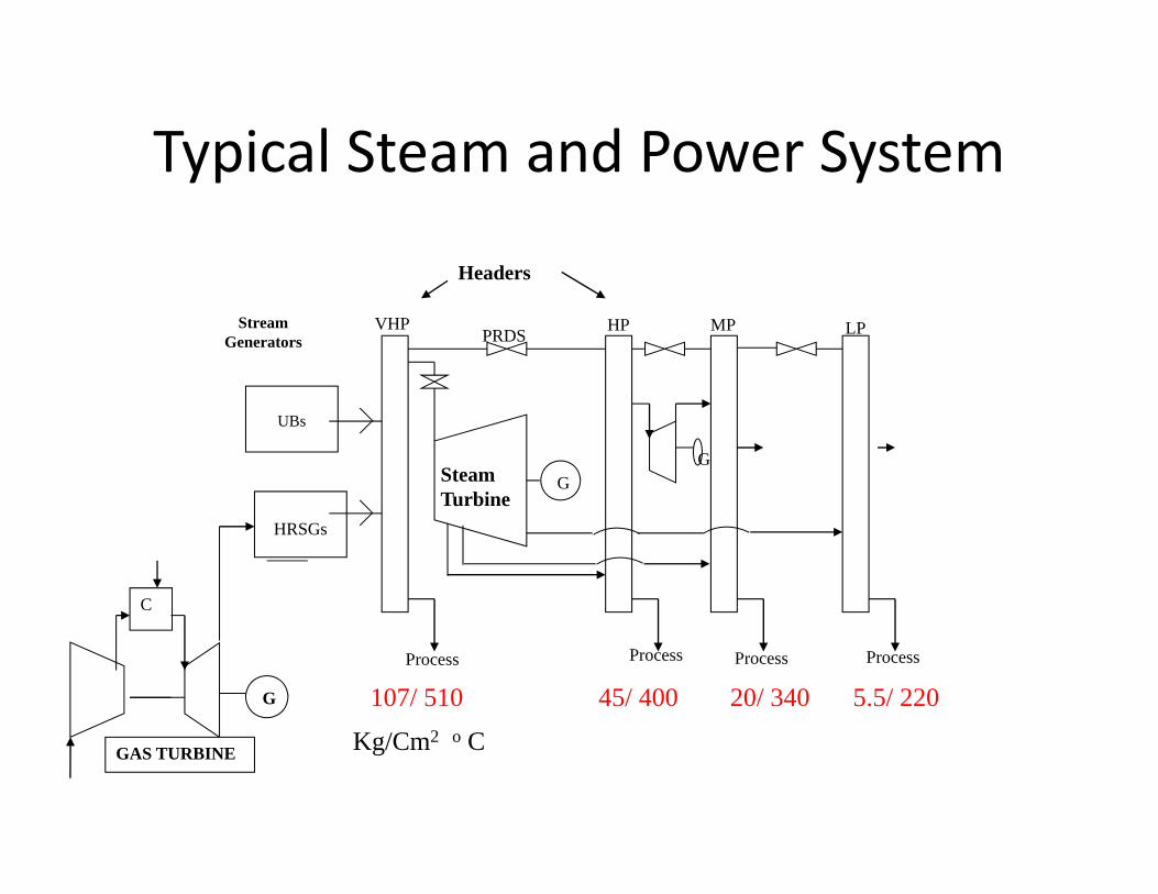
StreamGenerators
LP
Process
VHP HP MPPRDS
Process ProcessProcess
HRSGs
UBs
G
Typical Steam and Power System
Headers
107/ 510 45/ 400 20/ 340 5.5/ 220
Kg/Cm2 o C
C
G
GAS TURBINE
GSteam Turbine

Steam and Power system Dynamics
Steam System
Power System
Fuel System
Upsets in one system can influence the other
Modelling and Simulation

Instantaneous response
• Assume sudden Load Reduction and instantaneous change in generation
1.0
.8
Powerp.u Load, PL
Time (Sec.)
Generation Pg
Frequency
Time (Sec.)
50 Hz

Rotor Inertia
• At steady state :Turbine Torque (Pm) = Load Torque( (Pel)
• During transient :Speed = ∫((Pm – Pel) / Ta ) dt
• Ta = Acceleration time or inertia constant (function of moment of inertia)
Typical values: Ta = 9 ‐ 12 sec

Acceleration/ Deceleration
→ me
Pg
Deviation area is indicative ofacceleration/ deceleration
PL

PL → me
Pg
Delay due to the cumulative effects of Governor, hydraulic passages,turbine
n or f
→ t
Frequency or SpeedvariationDue to the above :
Governor Response
Settling Speed higher

‐
Xp○ ○○
Hydraulic relays time constant
Inflow(Qi) α ΔXp
Qi = volumetric
displacement of oil
= Ap . dxsm/dtKpΔXp = Ap sxsm
Xsm
ΔXsm1
Tsm .SΔ Xp
bLever gain

HP TURBINE TIME CONSTSANT
T4 = Steam mass inside turbine
Mass flow through HP turbine → Kg / Sec 207.4
Volume x Density= 0.844 (m3) (1 / 0.02337) = 36.114
T4 = 36.114 / 207.4 = 0.17 Sec.
VHP includes : ‐ Volume in inlet portion up to 1st stage.‐ all piping connections‐ blading
IP Turbine : 0.27 Sec
LP Turbine : 0.47 Sec
TReheaterr : 10 to 20 Sec.


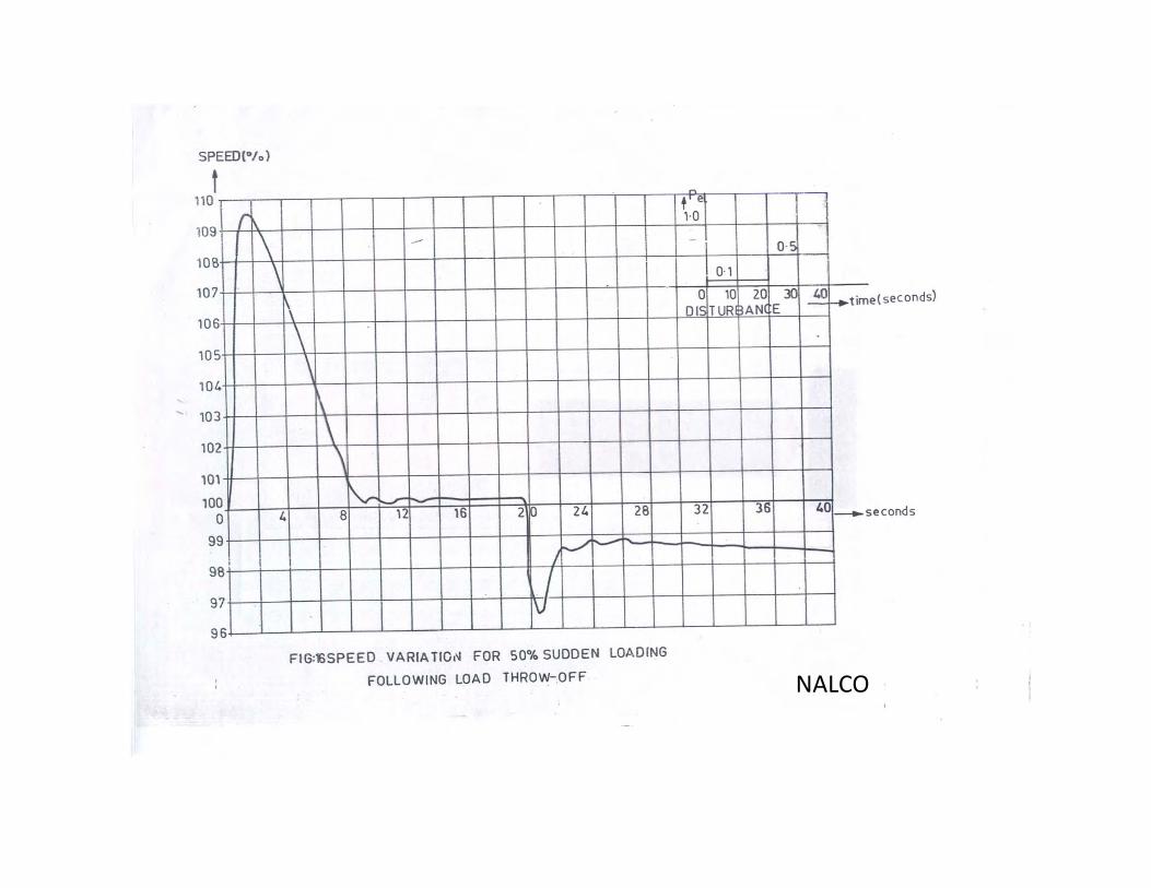
NALCO
NALCO

GNFC Bharuch
GNFC Bharuch

GNFC Bharuch

GNFC Bharuch