Embed Size (px)
Citation preview

Lecture 14-1Lecture 14-1
Computer Science 425Distributed Systems
CS 425 / CSE 424 / ECE 428
Fall 2012
Computer Science 425Distributed Systems
CS 425 / CSE 424 / ECE 428
Fall 2012
Indranil Gupta (Indy)
October 11, 2012
Lecture 14
NetworkingReading: Chapter 3 (relevant parts)
2012, I. Gupta, K. Nahrtstedt, S. Mitra, N. Vaidya, M. T. Harandi, J. Hou
Lecture 14-2Lecture 14-2
HW2 due nowHW2 due now

Lecture 14-3Lecture 14-3
Our Distributed System DefinitionOur Distributed System Definition
A distributed system is a collection of entities, each of which is autonomous, programmable, asynchronous and failure-prone, and communicating through an unreliable communication medium.
• Our interest in distributed systems involves – design and implementation, maintenance, study, algorithmics
• Entity=a process on a device (PC, PDA)
• Communication Medium=Wired or wireless network
Focus of this lecture

Lecture 14-4Lecture 14-4
So far…So far…
• Abstract distributed system – collection of processes over a communication medium
• Protocols/algorithms for synchronization, snapshots, multicast, election, mutual exclusion, failure detectors, p2p, Hadoop
• Intended to work in any distributed group of processes1. E.g., Group of processes on computer hosts
2. E.g., Group of processes on mobile devices
• For most of this course, we’ll focus on (1): computer hosts over the Internet

Lecture 14-5Lecture 14-5The Internet (Internet Mapping Project, color coded by ISPs)
PCs,routers,switches…=nodes
links=edges

Lecture 14-6Lecture 14-6
Internet 5-Layer Networking StackInternet 5-Layer Networking Stack
Messages (UDP) or Streams (TCP)
Application
Transport
Internet
UDP or TCP packets
IP datagrams
Network-specific frames
MessageLayers
Underlying network
Data Link Layer
This is where all distributed algorithms/techniques run
Lecture 14-7Lecture 14-7
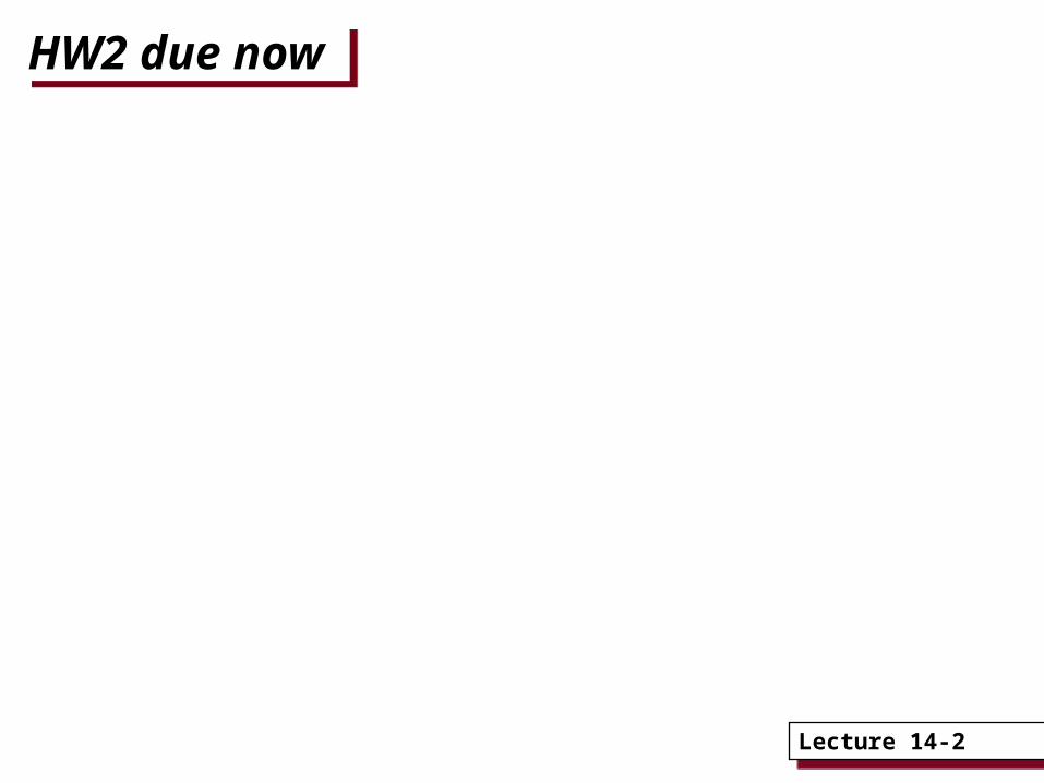
Routing Algorithms Routing Algorithms Nodes connected in some topology. Routing algorithm runs at
network layer in each node.
Goal of routing algorithm: given the destination IP address in packet, determine the “next hop”
thus determine the route for each packet as it travels through the net
dynamically update routing information to reflect failures, changes (e.g, router joins and leaves) and congestion (overloaded router)
Two approaches: Distance-vector (e.g., RIP)
Every node knows the next-hop for each possible destination LAN
Link-state (e.g., OSPF)
Every node knows status of every “link” in the network
In both, information maintained as a table
Tables updated either
Proactively – periodically, or
Reactively – when a neighbor/some link status changes
NETWORK/INTERNET LAYER

Lecture 14-8Lecture 14-8
Distance Vector RoutingDistance Vector Routing
• Also termed as distributed Bellman-Ford algorithm or Ford-Fulkerson algorithm, included in RIP (Routing Information Protocol), AppleTalk, and Cisco routers.
– Each node/router maintains a table indexed by each destination node. Entry gives (best known distance to destination, best next-hop for destination)
– Once every T seconds, each router sends to each neighbor its own entire table. Neighbor uses this to update its own table. (proactive)

Lecture 14-9Lecture 14-9
Distance Vector Routing Distance Vector Routing
A B
D E
C
Hosts or LANs
Routers
1
3
6
45
2
To Link Cost
B 1 1
C 1 2
D 3 1
E 1 2
A local
To Link Cost
A 2 2
B 2 1
D 5 2
E 5 1
C local
Routing Table for A
Routing Table for C
To Link Cost
A 1 1
C 2 1
D 4 2
E 4 1
B local Routing Table for B
Link number (all links have cost=1)

Lecture 14-10Lecture 14-10
Distance Vector RoutingDistance Vector Routing
+, then min across neighbors
Costs only (next hop omitted)

Lecture 14-11Lecture 14-11
Pseudo-Code for RIPPseudo-Code for RIP
Send: Each t seconds or when Tl changes, send Tl on each non-faulty outgoing link.Receive: Whenever a routing table Tr is received on link n:
for all rows Rr in Tr {if (Rr.link not equal n) {
Rr.cost = Rr.cost + 1;Rr.link = n;if (Rr.destination is not in Tl) add Rr to Tl; // add new destination to Tlelse for all rows Rl in Tl {
if (Rr.destination = Rl.destination and (Rr.cost < Rl.cost or Rl.link = n))
Rl = Rr;// Rr.cost < Rl.cost : remote node has better route// Rl.link = n : remote node is more authoritative
}}
}

Lecture 14-12Lecture 14-12
Link State RoutingLink State Routing
• Each router must1. Discover its neighbors and learn their network addresses
– When a router is booted up, it learns who its neighbors are by sending a special Hello packet on each point-to-point link.
– The router on the other end sends back a reply.
2. Measure the delay or cost to each of its neighbors
– A router sends a special Echo packet over the link that the other end sends back immediately. By measuring the round-trip time, the sending router gets a reasonable delay estimate.
3. Construct a packet telling all it has just learned.
– Broadcast this packet

Lecture 14-13Lecture 14-13
Link State RoutingLink State Routing
• A router broadcasts a link-state-advertisement (LSA) packet after booting, as well as periodically (or upon topology change). Packet forwarded only once, TTL-restricted
• Initial TTL is very high, since need it to get to every router

Lecture 14-14Lecture 14-14
Link State RoutingLink State Routing
4. Broadcast the LSA packet to all other routers.• Each packet contains a sequence number that is incremented for each
new LSA packet sent.
• Each router keeps track of all the (source router, sequence) pairs it sees. When a new LSA packet comes in, it is checked against these pairs. If the received packet is new, it is forwarded on all the links except the one it arrived on. (Thus old LSA packets are dropped)
• The age of each packet is included and is decremented once per time unit. When the age hits zero, the information is discarded. Initial age = high. Such state is often called soft state.
5. For routing a packet, since the source knows the entire network graph, it simply computes the shortest path (actual sequence of nodes) locally using the Dijkstra’s algorithm. It can include the path in the packet, and intermediate nodes simply follow this route to decide their next hop for the packet.

Lecture 14-15Lecture 14-15
Transport Layer =Transmission Control
Protocol
Transport Layer =Transmission Control
Protocol • Function 0 – provide an application with a connection-oriented view of the network (IP is connectionless)
• Function 1 (Message decomposition and reassembly): Breaks messages into packets at the transmitting end and reassembles packets into messages at the receiving end.
– E.g., using identification and fragment offset fields in IPv4 header
• Function 2 (Multiplexing and demultiplexing): Multiplexes several lower-rate sessions, all from the same source and all going to the same destination, into one session at the network layer.
• Function 3 (Reliable communication): Provides reliability to the application by acks + retransmissions in an end to end manner
• Function 4 (End-to-end congestion/flow control): Reduces rate at which data is sent when congestion is detected in the network. (TCP friendliness)
• Function 5 (Ordering): Of packets within a stream - FIFO• All these functionalities are a part of TCP.
TRANSPORT LAYER

Lecture 14-16Lecture 14-16
DNS: Domain Name SystemDNS: Domain Name System
People: many identifiers:– SSN, name, UIN, etc.
Internet hosts, routers:– IP address (32/64 bit) - used
for addressing datagrams
– Resource “name”, e.g., URL sal.cs.uiuc.edu – human-readable format
Q: given a resource name, how does a client find out the IP address of the service/server?
Domain Name System:• distributed database
implemented in a hierarchy of many name servers
• application-layer protocol that is responsible for resolving names (address/name translation)
Lecture 14-17Lecture 14-17
DNS Name ServersDNS Name Servers
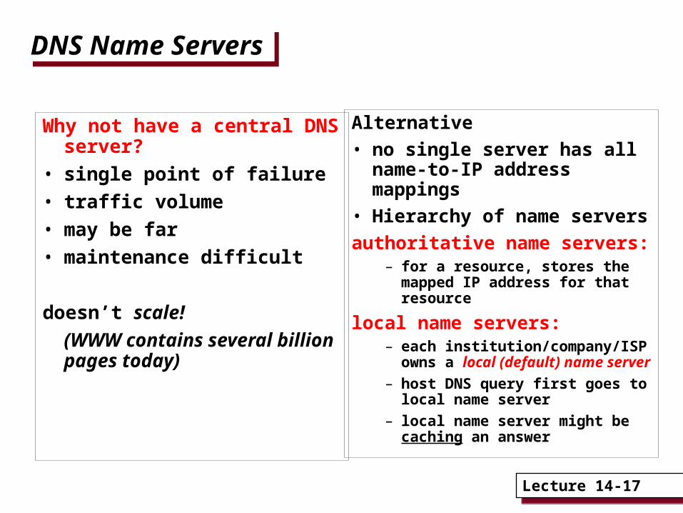
Alternative
• no single server has all name-to-IP address mappings
• Hierarchy of name servers
authoritative name servers:– for a resource, stores the mapped
IP address for that resource
local name servers:– each institution/company/ISP
owns a local (default) name server
– host DNS query first goes to local name server
– local name server might be caching an answer
Why not have a central DNS server?
• single point of failure
• traffic volume
• may be far
• maintenance difficult
doesn’t scale!
(WWW contains several billion pages today)

Lecture 14-18Lecture 14-18
DNS: Root Name ServersDNS: Root Name Servers
• contacted by local name server that cannot resolve query
• root name server:– contacts authoritative
name server if name mapping not known
– gets mapping
– returns mapping to local name server
• ~ 13 root name servers worldwide (as of ‘12)
Lecture 14-19Lecture 14-19
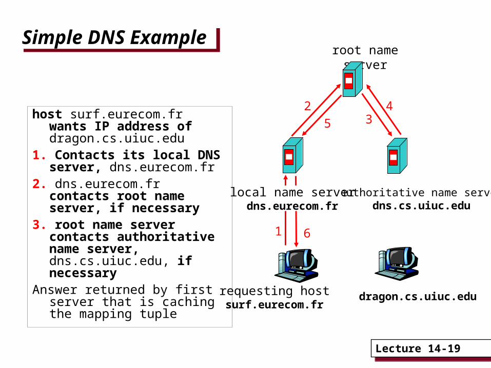
Simple DNS ExampleSimple DNS Example
host surf.eurecom.fr wants IP address of dragon.cs.uiuc.edu
1. Contacts its local DNS server, dns.eurecom.fr
2. dns.eurecom.fr contacts root name server, if necessary
3. root name server contacts authoritative name server, dns.cs.uiuc.edu, if necessary
Answer returned by first server that is caching the mapping tuple
requesting hostsurf.eurecom.fr
dragon.cs.uiuc.edu
root name server
authoritative name serverdns.cs.uiuc.edu
local name serverdns.eurecom.fr
1
23
4
5
6
Lecture 14-20Lecture 14-20
DNS ExampleDNS Example
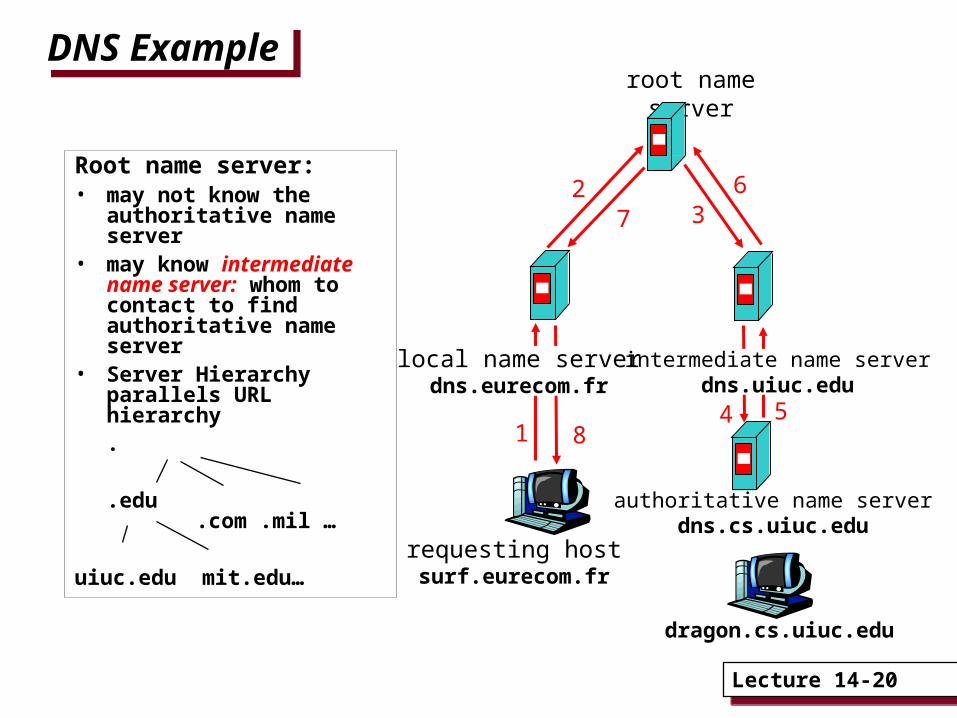
Root name server:• may not know the
authoritative name server
• may know intermediate name server: whom to contact to find authoritative name server
• Server Hierarchy parallels URL hierarchy
.
.edu .com .mil …
uiuc.edu mit.edu…requesting hostsurf.eurecom.fr
dragon.cs.uiuc.edu
root name server
local name serverdns.eurecom.fr
1
23
4 5
6
authoritative name serverdns.cs.uiuc.edu
intermediate name serverdns.uiuc.edu
7
8

Lecture 14-21Lecture 14-21
DNS: Iterated QueriesDNS: Iterated Queries
recursive query:• puts burden of name
resolution on servers along the way
• may fail if a server does not know next server to contact
iterated query:• contacted server replies
with name of server to querying server
• “I don’t know this resource name, but ask this other server”
• takes longer (more replies) but gives client more control
requesting hostsurf.eurecom.fr
dragon.cs.uiuc.edu
root name server
local name serverdns.eurecom.fr
1
23
4
5 6
authoritative name serverdns.cs.uiuc.edu
intermediate name serverdns.uiuc.edu
7
8
iterated query

Lecture 14-22Lecture 14-22
DNS: Caching and Updating RecordsDNS: Caching and Updating Records
• Once (any) name server learns mapping, it caches mapping
– cache entries timeout (disappear) after some time
• Update/notify mechanisms: insert new DNS entries– RFC 2136– http://www.ietf.org/html.charters/dnsind-charter.html
– Akamai/CDNs used this extensively to redirect HTTP requests to nearby caching servers

Lecture 14-23Lecture 14-23
SummarySummary
• Reading for this lecture: Chapter 3
• Midterm next Tuesday October 16th– Location: Here! (1310 DCL)
– Syllabus: Lectures 1-12, HWs1-2, MPs1-2.
– Closed book, closed notes. NO cheatsheets or calculators.
1. Multiple choice questions
2. Big problems: like HW problems, either design or application
• Practice midterm posted on Website (Assignments page) – no solutions will be posted
– Please use our office hours!

Lecture 14-24Lecture 14-24
Backup Slides (Not Covered)Backup Slides (Not Covered)

Lecture 14-25Lecture 14-25
ARP: Address Resolution Protocol between IP and Underlying Networks
ARP: Address Resolution Protocol between IP and Underlying Networks
• Most hosts are attached to a LAN by an interface board that only understands LAN addresses. For example, every Ethernet board is equipped with a globally unique 48-bit Ethernet address.
• The boards send and receive frames based on 48-bit Ethernet addresses. They know nothing about the 32-bit IP addresses.
• Address Resolution Protocol (ARP) maps the IP addresses onto data link layer addresses (e.g., Ethernet).
DATA LINK LAYER

Lecture 14-26Lecture 14-26
ARP ExampleARP Example Routers have multiple network
Interface cards/devices. Each interfacehas a different MAC/IP address.

Lecture 14-27Lecture 14-27
ARPARP
Suppose host 1’s IP layer (192.31.65.7) gets a packet from its transport layer destined for 192.31.65.5 (host 2)?
• Host 1’s IP layer broadcasts an ARP packet onto the Ethernet asking: ``Who owns IP address 192.31.65.5?''
• Host 2 responds with its Ethernet address (E2).• The IP layer on host 1 builds an Ethernet frame addressed to E2, puts the IP packet in the payload field, and transmits it on the Ethernet.• The Ethernet board of host 2 detects this frame and causes an interrupt, to deliver the packet to the IP layer on host 2.Thus, the packet is transmitted from host 1’s IP layer to host 2’s IP layer
Lecture 14-28Lecture 14-28
ARPARP• The performance of ARP can be improved by
caching the broadcast results.
• Host 1 can include its own IP to Ethernet mapping in the ARP packet.

Lecture 14-29Lecture 14-29
ARPARP
Suppose host 1’s IP layer (192.31.65.7) gets a packet from its transport layer with destination address set to 192.31.63.8 (host 4)?
• Host 1’s IP layer broadcasts an ARP packet onto the Ethernet asking: ``Who owns IP address 192.31.63.8?''
• Router E3/F1 responds with its Ethernet address (E3).• The IP layer on host 1 transmits an Ethernet frame addressed to E3• The E3 Ethernet board of router F1 receives the frame and delivers it to the IP layer on F1• F1’s IP layer knows from the destination address of 192.31.63.8 in the packet that it has to be next sent to 192.31.60.7. • F1’s IP layer sends an ARP on the FDDI ring for IP address 192.31.60.7. • Router E4/F3 replies.• F1’s IP layer transmits an FDDI frame (containing the packet) addressed to F3• The FDDI board of F3 receives the frame, and delivers it to the IP layer.• F3 knows from the destination address of 192.31.63.8 in the packet that it has to be next sent out to 192.31.63.8 through the interface E4• F3 does an ARP on the EE Ethernet for IP address 192.31.63.8 • Host 4 responds with E6• F3 transmits the packet inside an Ethernet frame addressed to E6, and it reaches host 4’s IP layer


![ECSE$425$Lecture$1:$ Course$Introduc5on$ · WhatECSE$425$isn’t ECSE$425,$Fall$2011,$Lecture$1$$ ©$2011$B.$H.$Meyer$ [Credit:$xkcd.com] 4](https://img.dokumen.tips/doc/110x75/5f63b10b4ca71b66f816a421/ecse425lecture1-courseintroduc5on-whatecse425isnat-ecse425fall2011lecture1.jpg)