Embed Size (px)
DESCRIPTION
Learning Programme Bm and Deflected Shape
Citation preview

ES3C7 Structural Design and AnalysisES3C7 Structural Design and AnalysisSELF-LEARNING EXERCISESELF-LEARNING EXERCISE
Deflected Shape and Bending Moments
Engineering Year 3: Civil Engineering

IntroductionIntroduction
The following self-learning exercise, of 69 frames, is ‘branched’
so that you can be given further instructions on points you do
not understand. It has been ‘scrambled’ to help you resist the
temptation to look at the next frame to find the answer to
questions. You will therefore find that you jump from frame to
frame. Your drawings are to be done free-hand and to reveal
possible answers use the ENTER key for each fly-in from the left
side.
LEARNING OUTCOME: On successful completion of the exercise
you should be able to draw the deflected shape and bending
moment diagram for a variety of structures without calculation.

To study the deflected shape of simply-supported beam begin at FRAME 1
To study the deflected shape of a propped cantilever beam begin at FRAME 6
To study bending moments in a cantilever beam begin at FRAME 16
To study bending moment diagrams of a simply
supported beam begin at FRAME 18
To study effect of rigid joints begin at FRAME 30
To study effect of pinned joints begin at FRAME 37
To study effect of roller supports begin at FRAME 39
To study bending moment diagrams of a portal frame begin at FRAME 44
To study uniformly distributed loading begin at FRAME 55
To study several point loads begin at FRAME 29
To study more complex structures and loading begin at FRAME 67
Summary (Summary (for later referencefor later reference))

Assuming elastic (small displacement) behaviour, draw the deflected
shape for the following beam
If you drew (a) go to Frame 7.
If you drew (b) go to Frame 9.
If you drew (c) go to Frame 4.
If you drew (d) some other shape, go to Frame 12.
FRAME 1

This is incorrect. If the
member is elastic it will
NOT ‘kink’ at any point
along its length.
Return to Frame 6.
FRAME 2

Go to Frame 8.
FRAME 3

Yes, the beam will deflect
as shown:
In this position the beam is compressed along the top edge and
stretched along the bottom edge.
Now go to Frame 6.
FRAME 4

Yes, the top side of the beam
is in tension near the fixed
support, and on the underside
elsewhere:
Now returning to the previous
example;
it can be seen that when the beam deflects, neither support
resists the bending (unlike the propped cantilever beam).
Now go to Frame 11.
FRAME 5

For the simply-supported beam
the side of the beam in tension
can be labelled as shown, i.e. with a ‘T’ on the edge that would be
convex when bent.
Now draw the deflected shape
for the propped cantilever beam:
If you drew (a) go to Frame 2,
(b) go to Frame 10,
(c) go to Frame 13,
(d) go to Frame 9.
FRAME 6
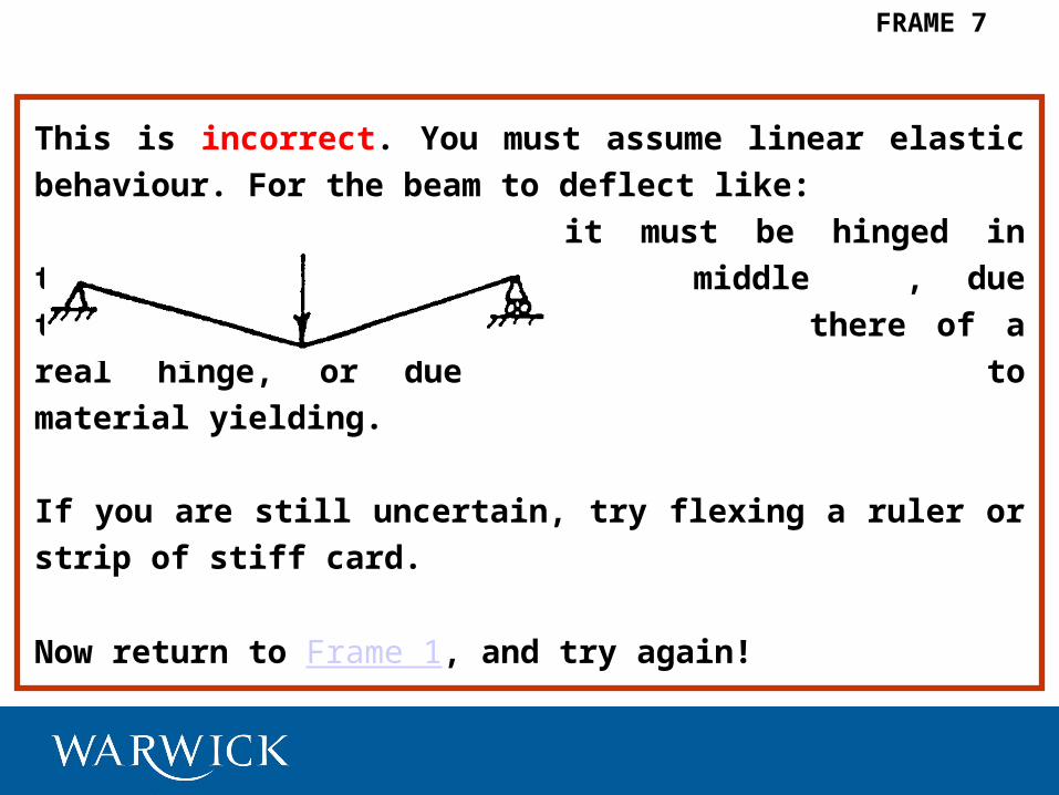
This is incorrect. You must assume linear elastic behaviour. For
the beam to deflect like:
it must be hinged in the
middle, due to the presence
there of a real hinge, or due
to material yielding.
If you are still uncertain, try flexing a ruler or strip of stiff card.
Now return to Frame 1, and try again!
FRAME 7

You have given the wrong distribution of tension. If we look at
the deflected shape:
Given the convex side of the beam is in tension, (i.e. the
‘outside’ of the curve), tension can be labelled thus for this
case:
Now got to Frame 5.
FRAME 8

No, this is not correct.
The supports shown above are knife-edges which do not
restrain rotation at the ends of the beam. So as it bends the
ends will deflect so:
Now return to Frame 1 (if you last attempted the simply-
supported beam) or Frame 6 and try again.
FRAME 9

No, this is not correct. At a fixed end the beam is held against
rotation.
It cannot hinge like this:
if it is linear elastic. Instead, the beam will deflect thus:
Now go to Frame 13.
FRAME 10

The supports for this beam
are knife-edges which do
not restrain rotation at the
ends of the beam.
So as it bends, the ends
will deflect thus:
Now got to Frame 16.
FRAME 11

No, the correct deflected shape is one of (a), (b), or (c).
If you cannot see why, try each in turn and read
through the relevant frames to find out why each is
right or wrong.
So now return to Frame 1.
FRAME 12

Yes, the beam will deflect as
shown:
Now label those lengths of side that will be in tension, as shown for
the simple supported beam in Frame 6.
If you drew: (a) go to Frame 8,
(b) go to Frame 3,
(c) go to Frame 5,
(d) go to Frame 15.
FRAME 13

No, this is incorrect. The turning effect produced by the forces
at A and B is anti-clockwise:
To resist this, the moment at B must be clockwise:
Now return to Frame 16 and try again.
FRAME 14

Go to Frame 8.
FRAME 15

If a cantilever is loaded by an end
point force:
then to keep end B ‘fixed’, a moment
M has to be applied by the support to
the cantilever, as shown. Which way should the end bending moment
be applied to ‘fix’ end B against rotation in this case:
If you think (a) (b)
Go to Frame 14 Go to Frame 20.
FRAME 16

Now draw the bending moment diagrams for
the structure shown in Frame 56, and then go
to Frame 19.
FRAME 17

The bending moment can be measured at any point along a member.
In the case of the cantilever:
The bending moment is the maximum
at fixed end, and varies linearly to zero at the free end. How does the
moment vary along this simply-supported beam?
If you think it varies:
(a) with maximum moment at the ends, and zero moment in the centre
(linear variation between these points), go to Frame 22,
(b) maximum in the centre, zero at the ends; linear variation,
go to Frame 24,
(c) some other variation, go to Frame 22.
FRAME 18

The bending moment diagrams are:
If you did not draw these correctly
and are still unsure of why you were
wrong, you may benefit from
reading the whole programme
again; otherwise go to Frame 29.
FRAME 19

Yes, a clockwise moment must be
applied at B.
In the case of the simply-supported beam, the member can be
visualised as TWO cantilevers joined together back-to-back in
the middle, where the slope is zero.
Now go to Frame 18.
FRAME 20

FRAME 21
Go to Frame 27.

You are wrong. If two cantilever moment diagrams are drawn
back-to-back they show the diagram for the simply-supported
beam.
Now go to Frame 24.
FRAME 22

Yes, this is correct:
Now continue with Frame 25.
FRAME 23

Yes, the bending moment will vary linearly from zero at the ends
to a maximum at the centre. We can plot the moment against
distance along the beam, using the beam line as the datum for
moment, to obtain ‘the bending moment diagram’.
For this case it is:
Now go to Frame 28.
FRAME 24

In this programme of directed learning we are
considering two-dimensional structures which contain a
variety of joints and support conditions. These have
differing effects on the deflected shape and bending
moment diagram.
Now got to Frame 30.
FRAME 25

The deflected shape, and lengths
of side in tension are:
If you drew:
(a) go to Frame 23,
(b) go to Frame 21,
(c) go to Frame 27.
FRAME 26

No, this is incorrect. The lengths
of the side in tension are:
Therefore bending moment diagram must cross from one side
to the other, at some position to the left of the applied load.
The correct shape is therefore:
Don’t understand why,
go to Frame 16 and work
through again.
Otherwise go to Frame 25.
FRAME 27

The sign convention is the moment diagram is always drawn on the
side of the member that is in tension due to bending. This can be seen
in the last slide (Frame 27):
Here the beam is always in tension on
the underside, and the b.m. diagram is
drawn below the beam. However, if
there are lengths of tension on the top
side of the member, then the b.m. diagram would cross to that side.
Now sketch the deflected shape, label the lengths of side in tension,
and draw the b.m. diagram for this propped cantilever:
and go to Frame 26.
FRAME 28

So far, we have considered situations with only one point load. In the
next few slides, more complex loading is considered. For example,
sketch the deflected shape of the following two-span continuous
beam, and label the lengths of side in tension. It should be assumed
that the effect of loading on the left-hand span is similar to that on the
right-hand span.
If you drew:
(a) go to Frame 32,
(b) go to Frame 34,
(c) Something else, go to Frame 52.
FRAME 29

Rigid joints. A perfectly rigid joint keeps the angles, between
the members meeting at that joint, constant. It is denoted
thus: However, the joint may of course rotate
when the deforms, forcing the member
ends to rotate by the same amount:
Angle at joint
between members
remains constant.
Now go to Frame 33.
FRAME 30

This is the correct deflected shape:
The b.m. diagram for
this condition is:
Note that the b.m. diagram for each member is drawn with that
member as datum. Obviously, for joint A to be in equilibrium the
two member end moments must be equal in magnitude, but
opposite direction. This is a useful check to see whether the
diagram is correct or not. Note also that it is usual to determine
b.m. diagrams on the underformed state of the structure. The
moment in the horizontal member is therefore constant as the
lever arm of the force is constant along this member.
Now go to Frame 37.
FRAME 31

Yes, the correct shape is:
Now draw the b.m. diagram.
If you drew:
(a) go to Frame 55,
(b) go to Frame 60,
(c) go to Frame 64,
(d) Something else, go to Frame 68.
FRAME 32

As this joint compels one member end to rotate
by the same amount as the other, it transmits
moment from one member to the other, just as if
they formed one continuous member. However, the b.m.
diagram is still drawn perpendicular to each member.
Draw the deflected shape for this:
and label the lengths of side in tension.
If you drew: (a) go to Frame 35.
(b) go to Frame 38.
(c) go to Frame 31.
FRAME 33

FRAME 34
Go to Frame 52.

No. For the frame to deflect in the way you have
chosen, there would have to be a vertical upward
force:
Return to Frame 33 and try again.
FRAME 35

FRAME 36
Go to Frame 40.

FRAME 37
Pinned Joints. A pinned joint acts like a hinge, and the
connected members can rotate about it. Pinned joints do not
transmit moment, and so the moment at the pinned end(s) of a
member must be zero. Draw the b.m. diagram for this structure:
If you drew: (a) go to Frame 40,
(b) go to Frame 36,
(c) go to Frame 50,
(d) Something else, go to Frame 45.
denotes pinned joint

This is not correct.
The rigid joint will transmit moment to the horizontal member
which is also flexible and will therefore deflect in flexure.
Now return to Frame 33 and try again.
FRAME 38

Roller Supports. The roller support is a knife-edge free to move
in one direction, but giving support in the perpendicular
direction:
In the exercises to follow, it should be assumed that such
supports are also capable of ‘holding-down’ the members to
which they are attached. Now draw
the deflected shape of this structure
and label the side lengths in tension.
Then turn to Frame 43.
FRAME 39
Provides support
Free to move

Due to the pinned joints, this
structure is a ‘mechanism’, and is
not in static equilibrium.
Always remember to check the stability of structures!
Now go to Frame 39.
FRAME 40

FRAME 41
Go to Frame 46.

FRAME 42
Go to Frame 53.

If you drew: (a) go to Frame 48,
(b) go to Frame 51,
(c) go to Frame 57.
FRAME 43

Yes. You have chosen the correct b.m. diagram. Following the same procedure, draw the b.m. diagram for:If you drew: (a)go to Frame 53,
(b)go to Frame 53,
(c)go to Frame 42,
(d)go to Frame 47.
(e) Something else, go to Frame 54.
FRAME 44

FRAME 45
Go to Frame 40.

The lengths of side in tension are:
Since the b.m. diagram must
be drawn at the tension side
it must cross-over the
horizontal member, but stay
on the right of the vertical
Thus: prop. The moment at the
roller is zero.
Now go to Frame 44.
FRAME 46

FRAME 47
Go to Frame 53.

No, the frame does not bend at the knee joint. This is
a rigid joint as described in Frame 30. You may
benefit from reading from Frame 30 again.
Otherwise return to Frame 43.
FRAME 48

FRAME 49
Go to Frame 46.

FRAME 50
Go to Frame 40.

Yes, you have chosen the correct deflected shape:
Now use the deflected shape to sketch the b.m.
diagram
If you drew: (a) go to Frame 44,
(b) go to Frame 49,
(c) go to Frame 41,
(d) Something else, go to Frame 46.
FRAME 51

No, you are not correct. The beam is continuous over the
central support so there should be no sharp changes of slope.
As the effects of loading on the two spans are similar, both
spans would have some lengths where the underside is in
tension.
[However, if, say, the left span was unloaded, then the shape
would be: ]
Now return to Frame 29 and try again.
FRAME 52

The correct solution is:
The deflected shape and length of sides are:
Now go to Frame 56.
FRAME 53

FRAME 54
Go to Frame 53.

Yes, this is the correct b.m. diagram:
Now if the number of point loads is increased, the diagram
becomes:
Now go to Frame 63.
FRAME 55

If arrived here from Frame 17 go to Frame 19 after drawing
b.m.
Now draw the deflected shape for these two
structures, labelling those lengths of the side in
tension.
Then turn to Frame 59.
FRAME 56

No, for the frame to deflect in the manner you have chosen,
there would need to be no end support at the vertical member.
However, the roller support on the inclined face forces the
vertical member upwards when the horizontal force is applied.
Now return to Frame 39 and try again.
FRAME 57
(See Frames 33
and 31.)

FRAME 58
Go to Frame 64.

The deflected shapes are:
If you are puzzled, try reading through from Frame 30 again.
Otherwise turn to Frame 17.
FRAME 59

FRAME 60
Go to Frame 64.

If arrived here from Frame 62 go to Frame 69 after drawing
b.m.
If arrived here from Frame 67 draw the deflected shape
and label those lengths of side in tension in this final
example:
Now turn to Frame 66.
FRAME 61

Now draw the b.m. diagram for the structure
shown in Frame 61,
If b.m diagram is drawn go to Frame 69.
FRAME 62

Now draw the b.m. diagram for this beam problem:
The loading on the right-hand span is uniformly distributed.
If you drew: (a) go to Frame 65,
(b) Something else, look again at Frame 55 again.
FRAME 63

It is known that the deflected shape is:
and also that the b.m. diagram is drawn on this side in tension.
We also know that the b.m. is zero at the extreme ends of the
beam, which are simply-supported, and that a linear variation
occurs between supports and/or load points. So, by inspection,
we can draw the b.m. diagram:
Now go to Frame 55.
FRAME 64

Correct. Uniformly distributed loading leads to a parabolic b.m.
diagram.
Now draw the deflected shape and b.m. diagram for this
structure:
Go to Frame 67.
FRAME 65

You should get either:
or
The correct shape depends upon the relative effects of the
horizontal and vertical loading. If vertical load dominates, (b) is
correct.
Now go to Frame 62.
FRAME 66

The structure will deflect as:
and the b.m. diagram will be
The horizontal reaction at A is zero, and therefore if the
moments are to be determined on the undeformed shape, then
there is zero moment in the column. The beam then behaves as
a propped cantilever. If the moments are determined on the
deformed shape then moment ‘V‘ will lead to b.m. in the
column, which will therefore bend. Now go to Frame 61.
FRAME 67
H = 0

FRAME 68
Go to Frame 64.

The b.m. diagrams are:
To correspond to the deflected shapes in Frame 66.
If you have already seen Frame 66 the exercise has ended, and
so you go to Frame 70.
FRAME 69

The END
Acknowledgments:
This programme of self-learning was developed pre-1987 by a
third year undergraduate student as part of a third year
individual project. Dr Mottram thanks this unknown student and
supervisor (Ian May, now Professor at Heriot-Watt Univ.) for
their contribution so that we have this excellent self-learning
programme on deflected shape and bending moments of two-
dimensional structures.
J. T. Mottram Sept. 2006
FRAME 70