Embed Size (px)
Citation preview

Learning outcomes
After you complete this chapter and the relevant learning experiences you will be able to:
relate the historical development of electricity as our major energy source
describe the modern methods of electrical generation
explain the principles for generating electricity from renewable energy sources
explain the reasons for the adoption of alternating current (a.c.) for the main electricity power supply system
describe the advantages and applications of modern direct current (d.c.) transmission
identify the conductors and their purpose in a three-phase distribution system
illustrate the stages of transmission and distribution of electricity from generation to consumers
illustrate the different arrangements of distribution to consumers
describe the arrangements for electricity distribution within an electrical installation
discuss the processes for the connection of electricity to a consumer’s installation and the need for compliance with safety standards.
1electrical energy–past,
present and future
01 - Pethebridge vol1 7e.indd 101 - Pethebridge vol1 7e.indd 1 10/9/09 2:23:21 PM10/9/09 2:23:21 PM
SAMPLE C
HAPTER

E L E C T R I C A L W I R I N G P R A C T I C E — V O L U M E 1
2
phenomena have been applied practically, developing the
electrotechnology industry we have today. A summary of this
development is given in Table 1.1 and Table 1.2.
Brief history of the electricity supply industry Electrical energy cannot be stored in large quantities.
Therefore bulk supplies of electrical energy must be fed
directly from the generating station through a transmission
and distribution system to the consumer. This need led to
the development of the electricity supply industry.
Immediately following the publication of the results
of Faraday’s famous 1831 experiments, many practical
generators were constructed by inventors. Their aim was to
produce a supply of direct current that would take the place
of the battery as a source of electrical energy.
The fi rst d.c. generators, also known as dynamos, were
produced for experimental purposes. Later, dynamos were
produced for electroplating and for supplying the arc lamp.
Used for lighting, the arc lamp produces an intense light
from an arc created between two carbon electrodes. Some
of the fi rst machines in Britain were specifi cally designed
to supply the energy required for the arc lamps used in
lighthouses, but it was not long before the arc lamp was
being used for lighting public places.
The design of larger, more effi cient dynamos continued.
To give some indication of size, Edison’s famous Jumbo
dynamo of 1881 was rated at 1500 light 110 volt and was
driven by a 150 horsepower engine, equivalent to about
112 kW. By contrast, the larger generators in a base-load
power station today are rated up to 650 000 kW.
Before 1880, the primary purpose of most electrical
sources was to supply the electrical energy for arc lamps.
However, the open arc of these lamps produced gases that
were a fi re hazard, and the arc carbons and control gear
required constant maintenance. They were made only in
high ratings; accordingly, when the enclosed, small and
low-rated incandescent electric lamp became a practical
proposition, it quickly replaced the arc lamp in most
lighting applications.
The invention of the incandescent lamp heralded the
growth of public supply, but the early public supply systems
were nearly all direct current, were small and were often
owned by private companies. Municipal councils became
involved mainly because of their interest in public street
lighting, and they absorbed many private supply companies.
In later years, large supply areas came under the control
of electricity enterprises, such as county councils in some
jurisdictions, that were formed for the sole purpose of
distributing electricity.
Electricity was fi rst sold to consumers about 130 years ago
and since then the electrical industry has reached a stage
where it encompasses so many branches and specialties
that the range of career opportunities seems limitless.
The technological advancement of a community
can be fairly accurately assessed by the amount
of electrical energy it uses. For example, the
consumption per person in South-East Asia is
considerably less than that of the United States (US).
The role of the electrical industry and the electrician in
high-technology societies is a vital one.
Regardless of the electrical worker’s particular
fi eld of activity within the industry, a sound technical
knowledge is necessary for work competence and
effi ciency. When carrying out installation work, theory
must be applied to wiring circuits, electrical machine
operation and control. Technical knowledge is also
necessary for a full understanding of the many rules
and regulations governing the installation, repair and
maintenance of wiring and equipment.
There are a number of ways in which a person
can qualify for an electrician’s licence. However,
the most common way is to undertake a training
program, usually through an apprenticeship, which
incorporates prescribed off-the-job and on-the-job
training standards. Before a licence is issued, an
applicant must demonstrate competence in ensuring
their work complies with all safety standards, including
demonstration of a sound knowledge of regulations,
in particular the Wiring Rules (Australian/New Zealand
Standard AS/NZS 3000).
However, for those embarking on the electrical trade,
it is well worth starting with a look at the fascinating
story of the development of electricity.
1.1 A brief history of electrical energy production and supply
Discoveries and development of electrical energyElectrical and magnetic phenomena have been known
and observed in the past as natural occurrences. Over
several millennia of human curiosity and enquiry, these
01 - Pethebridge vol1 7e.indd 201 - Pethebridge vol1 7e.indd 2 10/9/09 2:23:22 PM10/9/09 2:23:22 PM
SAMPLE C
HAPTER

3
C H A P T E R 1 E L E C T R I C A L E N E R G Y — P A S T , P R E S E N T A N D F U T U R E
Table 1.1 Historical discoveries of electrical phenomena
2000 BCE Hoang-ti Chinese emperor Used a form of the magnetic compass to steer war chariots across the plains of Tartary.
750–700 BCE Homer Greek epic poet The lodestone, a natural magnet, is referred to in Homer’s Odyssey.
1600 Dr William Gilbert Physician Published the fi rst major work in English attempting to describe electric forces and magnetic forces, providing the impetus for study and experiment by many philosophers.
1706–1790 Benjamin Franklin Statesman and scientist
Demonstrated that lightning is a form of electricity, with his kite experiment, and produced an explanation for the differences between positive and negative charge.
1736–1806 Charles Coulomb Physicist Proved the force of attraction between two electric charges is inversely proportional to the square of their distance, known as Coulombs Law. The standard unit for the quantity of electricity is named after him, i.e. a coulomb is a current of one ampere per second.
1745–1827 Alessandro Volta Physicist Developed the ‘pile’, consisting of a series of plates of silver and zinc interleaved by spongy matter soaked with a saline solution. The voltaic pile was the forerunner of the modern dry cell and was used by scientists in experiments for the next 25 years. The unit of electromotive force, the volt (V), is named after him.
1775–1836 André Ampère Physicist Said to be the founder of electrodynamism (electromagnetism) and proposed Ampère’s Law, relating the circulating magnetic fi eld in a closed loop to the electric current passing through the loop. He is remembered in the name of the unit of electric current, the ampere (A).
1777–1851 Hans Christian Oersted
Chemist and physicist
Discovered that a conductor carrying electric current produces a magnetic fi eld.
1787–1854 Georg Ohm Physicist Formulated Ohm’s Law which states the relationship between current in a circuit and the voltage applied to the circuit. The unit of resistance, the ohm (Ω), is named after him.
1791–1867 Michael Faraday Chemist and physicist
Discovered electromagnetic induction, the principle underlying the conversion of mechanical to electrical energy in modern generators. He produced the fi rst transformer, which forms the basis of our modern transmission and distribution systems. He has been called the father of modern electrical engineering.
1824–1887 Gustav Kirchhoff Physicist Among other notable discoveries, he developed laws to calculate current and voltage in complex circuits. In their simplest forms, these have become intuitive to the competent electrotechnology practitioner.
1831–1879 James Clerk Maxwell
Mathematician and physicist
Set the foundation for modern physics with his theoretical work on kinetics and electromagnetism. He was the fi rst to express the basic laws of electricity and magnetism in a unifi ed way.
1857–1894 Heinrich Hertz Physicist Working on the theories developed by Maxwell, he discovered the existence of electromagnetic waves. The unit of frequency, hertz (Hz), is named after him.
01 - Pethebridge vol1 7e.indd 301 - Pethebridge vol1 7e.indd 3 10/9/09 2:23:23 PM10/9/09 2:23:23 PM
SAMPLE C
HAPTER

E L E C T R I C A L W I R I N G P R A C T I C E — V O L U M E 1
4
Gradually, as alternators (generators that produce
alternating current), motors, transformers and equipment
progressively improved, three-phase a.c. generation,
transmission and distribution was adopted worldwide.
This was due mainly to economies in transmission and to the
simplicity and effi ciency of transformation from high to low
voltage or vice versa. Most modern Australian systems are of
a standard three-phase a.c. type.
Table 1.2 Milestones in the utilisation of electricity
1846–1914 George Westinghouse, Entrepreneur and businessman
Transformed the ideas of great inventors and engineers like Tesla into commercial reality. These included the transformer and the induction motor, heralding the a.c supply system we have today.
1847–1931 Thomas Edison, Inventor and entrepreneur
Produced the fi rst commercial incandescent lamp and developed the fi rst major electrical distribution system based on direct current.
1856–1943 Nikola Tesla, Engineer Tesla’s patents and theoretical work form the basis of the alternating current electrical system we know today. He developed the a.c. motor (also known as an induction motor), which is probably the most important single development in the industrial use of electricity. A great engineer.
1862–1919 Mikhail Dolivo-Dobrovolsky, Engineer, electrician and inventor
Accredited with developing the three-phase a.c. system.
1857 First commercial use of an arc lamp in a lighthouse at Dungeness, England.
1863 Portion of Sydney lit up on 11 June by a high-powered arc lamp on Observatory Hill.
1879 Electricity fi rst sold to the public in the USA.
1880 First public supply in Melbourne, Victoria (VIC).
1881 First public supply in England at Godalming.
1883 First public supply in Brisbane, Queensland (QLD).
1883 First public supply in Adelaide, South Australia (SA).
1888 First public supply in Tamworth, New South Wales (NSW).
1891 First public supply in Perth, Western Australia (WA).
1892 First public supply in Sydney, NSW.
1893 First public supply in Hobart, Tasmania (TAS).
1920s and 1930s Establishment of state owned and operated electricity generation and supply systems.
1994 Following New Zealand’s lead, Australian governments agreed to the introduction of competition in the generation, distribution and supply of electricity.
1994–1996 Corporatisation of state owned generation and distribution assets: some sold to private operators and some operated by state governments.
1996 Establishment of the National Electricity Market Management Company Limited (NEMMCO) to manage the marketing of electricity in the new competitive climate and maintain security of the power system.
1998 The National Electricity Market (NEM)* commenced a wholesale market for electricity supply in the interconnected power systems of QLD, NSW, Australian Capital Territory (ACT), Snowy Hydro Limited, VIC and SA.
2000s Progressive implementation of competition in the retailing of electricity, allowing end-users to choose their energy supplier. This has required the installation of new energy meters and information technology systems to process transfers of customers between registered energy retailers.
2005 Tasmania became a participant in the NEM with the interconnection of its power system to Victoria via the undersea cable across Bass Strait known as BassLink.
* The vast and sparsely populated distance between western and eastern Australia make it uneconomical for WA to be interconnected to the NEM power systems; however, WA is embarking on a similar competitive energy market, expected to be operating by 2010.
01 - Pethebridge vol1 7e.indd 401 - Pethebridge vol1 7e.indd 4 10/9/09 2:23:24 PM10/9/09 2:23:24 PM
SAMPLE C
HAPTER

5
C H A P T E R 1 E L E C T R I C A L E N E R G Y — P A S T , P R E S E N T A N D F U T U R E
Practical power alternators:
iron core
Figure 1.1 Principles of electrical generation
1.2 Modern generation methods
The bulk of electrical energy produced today is obtained from
a rotating turbine attached to an electrical generator. Energy
used to drive turbines is extracted from steam, fl owing water,
hot gases and wind. In Australia, as in most other countries,
the prime source for producing steam to drive turbines is
coal. However, there are exceptions, such as France, where
coal contributes less than 4 per cent and nuclear energy is the
prime source. Other fuels used to produce steam are natural
gas, petroleum and concentrated sunlight.
Hydroelectric systems use the controlled fl ow of water
from dams to drive turbine generators. In some suitable
coastal locations the energy from tidal fl ows is another
source used to drive turbine generators.
In gas turbine generators the hot gases produced by
burning natural gas or oil are used to directly drive the
turbine. More recently these are being supplemented with a
variety of renewable energy sources.
Modern generating systems fall into the following
groups:
• power stations using thermal energy released from
burning coal, oil or natural gas to produce steam or hot
gases, known as thermal stations
• power stations using thermal energy released by nuclear
reaction, known as nuclear power stations
• power stations using the kinetic energy of moving water,
known as hydroelectric stations (the most common form
of renewable energy)
• other renewable energy sources such as biogas from
landfi ll, geothermal, solar energy or kinetic energy from
wind and wave movement.
In addition to these there are many small diesel-engine
driven generators for electricity supply in areas remote from
the main power network and these are becoming more
common as standby supply in non-domestic installations.
Thermal power stations utilise the heat energy derived
from burning coal, oil or natural gas to convert water to
steam, and the steam is used at high pressure to drive a
turbine that is directly coupled to an alternator producing
electrical energy. The concept is illustrated in Figures 1.1
to 1.3. Coal and nuclear thermal power plants may take
many hours, if not days, to achieve a steady state power
output. Since they require a long period of time to heat up to
operating temperature, these plants are used to supply large
amounts of base-load demand.
The voltage (V), or pressure, at which the current is
produced ranges from 11 000 V to 23 000 V. Transformers are
used to ‘step up’ the voltage for transmission and ‘step down’
for utilisation of the electrical energy. The ease with which
voltage can be transformed is one of the main advantages of
using a.c.
Although nuclear power stations are similar in many
respects to thermal power stations, they are identifi ed
separately because of the additional equipment required to
control the process, the associated risk of a nuclear accident,
and the problems of nuclear waste containment.
However, nuclear electricity generation is well established
in the USA, Canada, Europe, India, Japan and China.
Preliminary work was commenced at Jervis Bay, NSW, for the
fi rst Australian nuclear power station, but this work ceased
in 1974.
The Intergovernmental Panel on Climate Change
(IPCC), a peak scientifi c body of the United Nations,
concluded in their Fourth Assessment Report. Climate
Change 2007 that our climate is warming as a result of
greenhouse gases produced mainly from human activity,
in particular, from gas emissions into the atmosphere from
01 - Pethebridge vol1 7e.indd 501 - Pethebridge vol1 7e.indd 5 10/9/09 2:23:24 PM10/9/09 2:23:24 PM
SAMPLE C
HAPTER

E L E C T R I C A L W I R I N G P R A C T I C E — V O L U M E 1
6
Boiler
Steam turbine
Alternator—typical ratings are 250 to 650 MW at 23 kV
Coal pulverisor
Coal delivery
Burner
Superheated steam
Boiler drum
Step-up transformer
Flow waterpump
Water from cooling tower of lake
Cooling water return
Hot gas
Flue—includes dust collection system to prevent heavy particles from entering the atmosphere
1. The heat energy stored in coal is released by burning it in a furnace to raise steam at high pressure and temperature in the boiler.
2. The steam is superheated with hot gases from
the furnace.
3. The superheated steam is fed to the turbine, where it strikes the blades, rotating thealternator shaft.
4. In producing alternating current (a.c.) at a
frequency of 50 Hz, the turbine rotates at:
5. Depleted steam is condensed (back to water) and returned to the boiler, continuing the cycle.
Condenser
1
2
3
4
5
330 kV or 500 kV to switchyard for transmission to distribution sub-stations
Alternator
Preheater
Exhaust
Energy reduced exhaust gas
Compressor stageTurbine stage
Combustion chamber
High pressure combustion gases
500 ºC
Gas supply
1. Air is drawn into the compressor and compressed. 2. Exhaust gases heat the compressed air in the preheater.3. Heated compressed air is fed to the combustion chamber. 4. Gas is burnt in heated compressed air in the combustion chamber producing high pressure combustion gases.5. Combustion gases are fed to the turbine, where they strike the blades, rotating the alternator shaft. 6. Energy reduced combustion gases are emitted as exhaust.In cogeneration systems the exhaust gas is used in space, water or process heating increasing the thermal efficiency on the system to as much as 90 per cent.
1
23
4
5
6
Transformer—type and rating depends on alternator output and load requirements
The rating of gas turbine units varies greatly from mobile units of a few hundred kilowatts to large complex units in the hundreds of megawatts range. The large units are often integrated with steam systems to increase their thermal efficiency and reduce overall greenhouse gas emissions.
Figure 1.2 Principles of coal-powered thermal generation
Figure 1.3 Principles of gas-powered thermal generation
01 - Pethebridge vol1 7e.indd 601 - Pethebridge vol1 7e.indd 6 10/9/09 2:23:25 PM10/9/09 2:23:25 PM
SAMPLE C
HAPTER
7
C H A P T E R 1 E L E C T R I C A L E N E R G Y — P A S T , P R E S E N T A N D F U T U R E
burning fossil fuels such as coal. This has prompted debate
on the question of using nuclear power (see Figure 1.4)
for electricity generation in Australia as an alternative to
coal. However, success with current research into clean coal
technology, which endeavours to collect and safely store
greenhouse gases produced from burning coal, means that
coal may remain the preferred fuel for base-load generation
in the immediate future.
1.3 Renewable energy and sustainable energy practices While greenhouse gases occur naturally in the atmosphere,
human activities such as land clearing and the burning of
fossil fuels are increasing the concentration of these gases.
In recognition of this problem, international efforts are
concentrated on curbing greenhouse gas emissions across all
sectors of the economy. These initiatives include providing
incentives to individuals and enterprises to adopt sustainable
energy practices. For example, individual consumers can
apply to purchase sustainable energy electricity from their
energy retailer, which commits itself to acquiring the
equivalent amount from renewable energy sources.
Sustainable energy is a term that means both an effi cient
use of energy from any source (that is, using less energy to
provide the same service) and energy from renewable sources
such as hydro, geothermal, solar, wind and tidal movement.
Note that renewable energy is not energy extracted from
materials such as the burning of fossil fuels, but is the
conversion of energy already existing in nature to other more
useful sources such as electricity. (The use of solar thermal
energy for hot-water systems is discussed in Volume 2.)
Renewable energy sources Hydroelectric power stations, such as those used in the
eastern states of Australia and in the South Island, New
Zealand, use the kinetic energy of moving water to drive
turbines. Hydroelectric generation is the fastest to respond
to increasing power demands, reaching full power in two
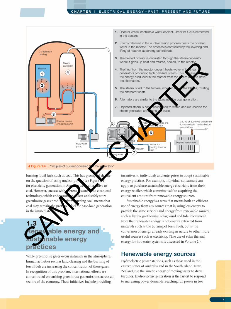
Figure 1.4 Principles of nuclear-powered thermal generation
1. Reactor vessel contains a water coolant. Uranium fuel is immersed in the coolant.
2. Energy released in the nuclear fission process heats the coolant water in the reactor. The process is controlled by the lowering and lifting of neutron-absorbing control rods.
3. The heated coolant is circulated through the steam generator where it gives up heat and returns, cooled, to the reactor.
4. The heat from the reactor coolant heats water in the steam generators producing high pressure steam. This process isolates the energy produced in the reactor from the steam used to drive the alternators.
5. The steam is fed to the turbine, where it strikes the blades, rotating the alternator shaft.
6. Alternators are similar to the types used in coal generation.
7. Depleted steam is condensed (back to water) and returned to the steam generator, continuing the cycle.
Steam turbine
Alternator—typical ratings are 250 to 650 MW at 23 kV
Step-up transformer Flow waterpump
Water from cooling tower of lake
Cooling water return
Condenser
330 kV or 500 kV to switchyard for transmission to distribution sub-stations
1
3
4
5
6
7
Reactor
Steamgenerator
Reactor coolantcirculation pump
2
Containmentbuilding
01 - Pethebridge vol1 7e.indd 701 - Pethebridge vol1 7e.indd 7 10/9/09 2:23:28 PM10/9/09 2:23:28 PM
SAMPLE C
HAPTER

E L E C T R I C A L W I R I N G P R A C T I C E — V O L U M E 1
8
to three minutes. These plants can provide both base-load
and peak-load demands for power at a relatively low cost,
provided suffi cient water is available.
The main local source of electrical energy in Tasmania
is hydroelectric, producing 60 per cent of Australia’s renew-
able energy (see Figures 1.5, 1.6a and 1.6b). BassLink,
commissioned in 2005, connects Tasmania to the eastern
Australia electricity grid, allowing the island state to sell
electricity from its major renewable source to the mainland
user. More importantly, it allows Tasmania to buy electricity
from the mainland during long periods of drought when dam
storage levels for electricity generation may fall substantially.
While conventional power stations need boilers to
produce steam to drive generators, some countries can do
without them as they can use steam produced from water
heated naturally underground; these schemes are termed
geothermal. The fi rst geothermal power station was built in
1913 at Larderello in Italy, and the second was commissioned
in 1958 at Wairakei in New Zealand. The Wairakei and the
Ohaaki (commissioned in 1989) power stations account
for about 8 per cent of the total generating capacity of the
Electricity Corporation of New Zealand.
Initially only a few renewable energy sources, such as
hydro and geothermal, have been considered viable by
electricity generators and distributors. However, through
government initiatives and the growing need to develop
other sources of renewable energy, their contribution to the
public supply network is increasing.
‘Hot rock’ technology is a form of geothermal energy
being developed in South Australia where the high thermal
energy that exists in rock some 3 kilometres (km) below the
earth’s surface is being retrieved to produce steam to drive
generators. The principles are shown in Figure 1.7.
Solar energy can be converted to electrical energy by
directing sunlight onto a photovoltaic (PV) array. PV solar
cells have been used for some time to produce small amounts
of power on satellite stations, and by telecommunications
companies for such applications as outback relay stations
and microwave communication systems. They are also used
for remote-area power supply (RAPS) systems. Rechargeable
batteries are an essential part of any RAPS system; they store
the electrical energy produced by the PV cells for times when
the demand for power exceeds supply, such as at night or
on an overcast day.
Step-up transformer
330 kV or 500 kV to switchyard for transmission to distribution sub-stations
3
4
5
6
1
1. The water stored behind a dam is released through huge pipes known as penstocks.
2. Inlet guide vanes direct the water through the water turbine.
3. The kinetic energy in the falling water is transferred to the turbine blades rotating the turbine and the attached generator. The guide vanes allow the shaft to spin at a controlled speed and regulate energy output.
2
PenstockWater discharge from holding dam
Turbine hall
Weir or river
Turbine discharge
Water turbine
Control vanes
Alternator—power network units mostly rated in the range of the tens of megawatts with output voltage from 11 to 23 kV
4. Water turbines have a relatively low rotational speed. So to produce alternating current (a.c.) at a frequency of 50 Hz the alternates are designed with more poles than steam turbine driven units. For example, a 24 pole alternator is rotated at 250 rpm.
5. Energy depleted water is discharged to a weir or river.
6. Discharge water is typically used for irrigation. Some turbine designs (e.g. Francis Turbine) can be used to pump water back to the holding dam.
In this system the alternator is used as a sychronous motor, taking power from the network during the off-peak periods to drive the turbine as a pump.
Figure 1.5 Principles of hydro power generation
01 - Pethebridge vol1 7e.indd 801 - Pethebridge vol1 7e.indd 8 10/9/09 2:23:30 PM10/9/09 2:23:30 PM
SAMPLE C
HAPTER

9
C H A P T E R 1 E L E C T R I C A L E N E R G Y — P A S T , P R E S E N T A N D F U T U R E
Individual consumers who are connected to the public
distribution system can supplement their electricity use by
installing a roof-mounted array of PV solar cells as shown in
Figure 1.8a. Although these systems supply clean renewable
energy they are initially expensive, even with a government
subsidy, and those who choose to install them do so on
environmental grounds. Their uptake is greater in countries
where the government subsidies are substantial. Large scale
PV power stations are currently in the planning stage, using
new generation solar cell technologies.
The use of heat from sunlight (i.e. solar thermal energy)
has commonly been used in solar hot-water systems for many
years. Now solar thermal energy is proving to be an effective
method for generating larger amounts of electricity. In these
systems inexpensive solar collectors are used to develop high-
temperature hot water for steam generators. A pilot plant has
been installed at Macquarie Energy’s Liddell Power Station
in the Hunter Valley (NSW) where it is used to supplement
coal use. A 2000 megawatt (MW) solar thermal power station
using this technology is planned for installation in the US.
The principle is shown in Figure 1.8b. Using thermal storage
technology the station is intended for base-load supply as an
alternative to coal, gas and nuclear power stations.
Two other sources of renewable energy, which have up
until the 1990s only been the subject of research in Australia,
are wind-generated and wave-generated electrical energy.
Magnetic field exitation control
Turbine
Three phase stator in which electricity is
generated
Hydro generatorsThe spinning speed of water turbines is relatively low compared with steam and gas turbines. Therefore to generate the standard frequency of 50 Hz hydro generators are designed with as many as 24 poles resulting in a machine of large rotor diameter and short axial length. Hydro generators have lower outputs than steam turbine machines; however, they provide the largest amount of ‘clean energy’ base-load supply in Australia with machines rated up to 250 MW.
Rotor carrying the coils that when energised
create the magnetic field
Figure 1.6a Features of a water turbine generator
Figure 1.6b Features of a steam turbine generator
Injectionwell
Productionwell
Heat exchanger
Feedpump
Condenser
Turbine
Alternator
12
5
4
3
Output to supply network
1. Water is injected deep into heat-bearing rocks.
2. The heat from the deep rocks is captured as steam and brought to the surface.
3. The steam gives up heat to a secondary (drive) fluid, which boils to become a high pressure vapour.
4. The high pressure vapour is fed to the turbine, where it strikes the blades and rotates the alternator shaft.
5. Depleted vapour is condensed (back to a fluid) and returned to the heat exchanger continuing the cycle.
Figure 1.7 Principles of geothermal power generation from hot rock
Turbine
Three phase stator in which electricity is generated incorporates hollow
conductors for water cooling
Magnetic field exitation and ancillary
cooling equipment
Rotor carrying the coils that when energised create
the magnetic fieldSteam and gas driven generatorsSteam and gas turbine driven generators are typically designed with 2 or 4 poles because of high optimum turbine speed. (Generating at the standard frequency of 50 Hz a 2-pole machine spins at 3000 rpm.) These generators are designed with relative small diameter rotors and long axial length. Steam turbine generators are the main source of base-load supply in Australia with machines rated upto 660 MW.
Hydrogen cooling
01 - Pethebridge vol1 7e.indd 901 - Pethebridge vol1 7e.indd 9 10/9/09 2:23:31 PM10/9/09 2:23:31 PM
SAMPLE C
HAPTER

E L E C T R I C A L W I R I N G P R A C T I C E — V O L U M E 1
10
Since the 1990s Australian state governments, together
with electrical energy companies, have embarked on the
development of wind farms as a cost-effective renewable
source of electricity generation. By 2006 Australia had a
wind-generating capacity in excess of 800 MW with the
expectation that this will increase substantially in the next
decade (see Figure 1.9).
Currently there are several wind farms throughout New
Zealand with a total capacity in excess of 170 MW.
In 1990, the Hydro-Electric Commission of Tasmania
commissioned a Norwegian company to study the feasibility
of installing a wave power plant on King Island in Bass Strait.
The study, completed in 1991, showed that the project was
not economical.
With this type of system, waves move into a narrowing
concrete channel and spill into a reservoir. Electricity is
generated as water runs through turbines back to the sea
at a lower level. A more promising method for harnessing
energy from the ocean involves use of special buoys that
capture the energy from wave motion in a hydraulic system
to drive on-board generators. Portugal is the fi rst country to
commercially harvest wave energy in this way with a wave
farm of three machines generating 2.25 MW and plans to
expand capacity to 70 MW.
The most exciting project in harvesting wave energy
is CETO technology, a system of underwater pumping
units invented in Australia. A commercial demonstration
farm is being developed in Western Australia for operation
in 2009.
Unlike other wave energy systems currently under
development around the world, the CETO wave power
converter is the fi rst unit to be fully submerged and to
produce high-pressure seawater from the power of waves.
By delivering high-pressure seawater ashore, the
technology allows the production of either zero-emission
electricity (similar to hydroelectricity) or zero-emission
freshwater (utilising standard reverse-osmosis desalination
technology). It also means that there is no need for under-sea
grids or high-voltage transmission, or costly marine qualifi ed
plants.
Service lines to distribution network
Main switchboard
Circuit protection devices
Service protection devices and metering
Photo- voltaic (PV) array
Grid connected inverter*
Final subcircuit for light, power and appliances
1
23
4
5
1. Energy from sunlight falling on the array of photo-voltaic cells is converted to d.c. electrical energy.
2. The d.c. from the PV array is fed into the grid connected inverter, which ‘inverts’ the d.c. to230 V a.c.
3. Supply from the inverter is fed to supply loads to the consumer’s installation or to the distribution network.
4. When the consumer’s demand is greater than the energy generated by the PV array, energy is supplied from the distribution network.
5. When the consumer’s demand is less than generated by the PV array, energy is supplied to the distribution network. In this way the consumer gains credits for the energy supplied.
* The grid connected inverter includes safety controls to cut off the supply from the PV array if it detects any interruption to the distribution network. This is necessary to guard against power quality issues for the network, interference with protection devices, equipment damage and personal safety hazards.
Figure 1.8a Application of direct solar power generation
1. Water is fed to pipes in the energy absorber.2. Sunlight strikes the CLFR collectors.3a. CLFR collectors are focused on the energy absorber,
reflecting the sunlight to roughly 30 times the intensity of sunlight at Earth’s surface.
3b. CLFR solar collectors track sun for optimum energy capture.
4. Solar energy focused on the energy absorber is converted to thermal energy in the form of high pressure steam (285ºC).
5. Steam is fed to turbines similar to conventional steam generation plants.
Compact linear Fresnel reflector (CLFR) solar collector
Energy absorber
Feed water
High pressure steam delivery
1
2
3a3b
5
4
Figure 1.8b Principles of solar thermal power generation AUSRA
1
01 - Pethebridge vol1 7e.indd 1001 - Pethebridge vol1 7e.indd 10 10/9/09 2:23:35 PM10/9/09 2:23:35 PM
SAMPLE C
HAPTER

11
C H A P T E R 1 E L E C T R I C A L E N E R G Y — P A S T , P R E S E N T A N D F U T U R E
CETO units are fully submerged and permanently
anchored to the sea floor, meaning that there is no visual
impact as the units are out of sight. Figure 1.10 shows how
wave power is converted to electricity. This also assists
in making them safe from the extreme forces that can be
present during storms. They are self-tuning to tide, sea
state and wave pattern, making them able to perform
in a wide variety of wave heights and in any direction.
CETO units are manufactured from steel, rubber and
hypalon materials, all proven for over 20 years in a marine
environment.
The detrimental effects on the world’s environment from
the burning of fossil fuels such as coal show that there is an
increased need for renewable forms of energy production.
Figure 1.9 Principles of wind power generation
Figure 1.10 How it works—CETO wave energy system CETO
1
2
3
5
Alternator
Pressurised sea water
Desalination plant
Sea water return
Water turbine
Output to supply network
1. The CETO wave power converter units produce high pressure sea water from the power of waves.
2. High pressure sea water is piped ashore where it is directed to electricity generation, desalination or both.
3. The kinetic energy in the high pressure sea water is transferred to the turbine blades rotating the turbine and the attached generator.
4. As with hydro generation, the alternator is designed with many poles in order to produce alternating current (a.c.) at a frequency of 50 Hz at the relatively low rotational speed of the water turbine. 46
5. Energy depleted sea water is returned to the sea.
6. High pressure sea water can be directed to desalination during periods (off-peak) when electricity demand is low. The water is fed through a reverse-osmosis process, supplementing fresh water reserves.
To fresh water reserves
CETO wave power converter units are moored to the seabed at depths from 15 to 50 metres
Spinner hub
Main bearing
Main shaft
Gear
Coupling
Fail-safe disk brake
Cooling system
Generator
01 - Pethebridge vol1 7e.indd 1101 - Pethebridge vol1 7e.indd 11 10/9/09 2:23:36 PM10/9/09 2:23:36 PM
SAMPLE C
HAPTER

E L E C T R I C A L W I R I N G P R A C T I C E — V O L U M E 1
12
However, the capital costs of these methods of generation
for large scale, grid-connected power remain high compared
with coal-fi red and gas-fi red methods. Economics seems
to be the main obstacle to the increased use of renewable
energy sources; however, with government initiatives such
as subsidies and carbon trading schemes, and emerging
renewable energy technology, its adoption should increase
substantially in the next decade.
Generating and using energy effi cientlyMuch of the thermal energy, such as steam or hot gases,
that is produced for direct use in manufacturing processes
tends to be lost to the atmosphere through fl ue and exhaust
systems. The same is true of thermal electricity generation
plants. The effi ciency of energy use can be increased by
utilising the waste energy to either generate electricity or
provide the thermal energy needed for other processes. For
example, a hospital might generate electricity using a gas
turbine, and the hot exhaust gases from the turbine could be
used to produce hot water and steam for hospital cleaning
and sterilising purposes (see Figure 1.3 on p. 6). Any excess
electricity could be fed into a public grid system, resulting
in a reduced cost of electrical energy for the hospital. This
arrangement is known as co-generation and is being used in
manufacturing processes where thermal energy is required.
The Building Code of Australia (BCA) and New Zealand
Building Code (NZBC) include requirements for buildings
to be more energy effi cient, achieved in part by the electrical
installation. You will learn more about this and sustainable
work practices in following chapters and as you progress
through your training.
1.4 Electricity transmission and distribution systems Generating stations are the main source of electrical energy,
but for this energy to be utilised, it must be conveyed from
the energy source to the consumer. Public supply fi rst
consisted of a large number of small power stations, many
privately owned and each supplying a relatively small local
area. Only in the large cities was the interchange of power
between supply authorities practicable. Consequently, in
the event of a severe overload or breakdown in the local
supply system a blackout would occur. The only way to avoid
a blackout would have been heavy investment in standby
power plants and this was uneconomical.
Supply engineers came to realise that the best way to
provide a reliable and economical supply was by state-
wide or country-wide transmission-line grids fed by large
generating stations. The power stations could be located
on fuel reserves, saving fuel transport and handling costs,
and the stations could be connected directly to a state’s grid
system. Many small, uneconomical power stations could
be shut down and their combined loads supplied by large,
effi cient units via the grid. Some of the advantages of this are:
• large generating units are more effi cient in operation
than small ones
• less reserve plant is required to supply peaks of supply
demand, or in an emergency
• many remote places, such as rural areas that would be
considered inaccessible to a normal supply system, may
be supplied by ‘tapping off ’ the state grid
• the interchange of power is possible both within the
grid system and interstate; the eastern grid scheme
interconnects the power systems of QLD, NSW, ACT,
VIC, SA, TAS and Snowy Hydro Limited; the New
Zealand grid interconnects the power systems of the
North and South Islands
• centralised control results in economies in both
generation and operation.
The eastern grid scheme of transmission requires
thousands of kilometres of high-voltage transmission lines.
A small percentage of these lines might be underground
where a concentrated load occurs in large cities, but the
major grid system is overhead as aerial lines. For complete
reliability and service, the design for the transmission system
must provide for the:
• continuity of supply under any conditions of breakdown,
overload or emergency
• full protection of the system from external or internal
hazards
• complete fl exibility of the system for maintenance, power
interchange or switching purposes.
Early in the 20th century, a controversy arose over the
respective merits of a.c. and d.c. systems. The disadvantage
of the d.c. system was the diffi culty it presented in changing
generated voltages to the high-voltage values needed for
effi cient transmission over any great distance, as shown in
Figure 1.11. Eventually the system evolved to the three-phase
a.c. system (HVAC) we have today.
Only in later years was this disadvantage overcome by
the development of a.c. to d.c. conversion and d.c. to a.c.
inversion equipment, leading to the successful installation
of some high-voltage d.c. (HVDC) transmission lines, as
illustrated in Figure 1.12.
1
01 - Pethebridge vol1 7e.indd 1201 - Pethebridge vol1 7e.indd 12 10/9/09 2:23:39 PM10/9/09 2:23:39 PM
SAMPLE C
HAPTER

13
C H A P T E R 1 E L E C T R I C A L E N E R G Y — P A S T , P R E S E N T A N D F U T U R E
Figure 1.11 Direct current (d.c.) and alternating current (a.c.) systems
Power transmitted is proportional to the voltage and the current.
Transmission power loss because heat in wires is in proportion to the current squared.For example, halving the current will reduce the power lost to one-quarter, i.e. (1/2)2.
Current
Transmission line
Load
Generator
Disadvantage of early d.c. systems:
Higher transmission voltage reduces the current and therefore the losses
Current
Transmission line
Generator (alternator)
a.c.
Lower transmission loss
Step-up transformer increases the voltage for transmission
Load
Step-down transformer decreases voltage suitable for the load
Advantage of a.c. systems:
Designation of a.c. conductors:The three-phase system has three active conductors, each known as a phase or line. They are most commonly designated by line numbers L1, L2 and L3; by their colour code (Clause 3.8), Red Active, White Active and Blue Active; as Phase 1, Phase 2 and Phase 3; or as A Phase, B Phase and C Phase.While the terms line and phase are, strictly speaking, not synonymous, in practice a load is more often referred to as being connected, say, between phase and neutral rather than between line and neutral, or between phases rather than between lines.
Some advantages of three-phase a.c. systems:
Low-voltage supply
L 1
L 2
L 3
Neutral
Single-phase loads can be distributedacross the three phases by use of a neutral conductor
Three-phaseinduction motor
Gives constant torque and power for a given load
Very efficient
Relatively cheap to manufacture
Load Load Load
Delivers power with less conductor material than a single-phase system
No electrical connection needed to the rotor
3
01 - Pethebridge vol1 7e.indd 1301 - Pethebridge vol1 7e.indd 13 10/9/09 2:23:40 PM10/9/09 2:23:40 PM
SAMPLE C
HAPTER

E L E C T R I C A L W I R I N G P R A C T I C E — V O L U M E 1
14
Both the thermal and hydroelectric power stations
generate three-phase power at voltages dependent on the
generator’s specifications. Typical generation voltages
are 11 kilovolts (kV), 17 kV, 22 kV and 23 kV for thermal
stations, and 6.6 kV, 11 kV and 22 kV for hydroelectric
generation. The generation voltage is usually too low for
long-distance transmission and must be stepped up by
transformers to transmission voltages with typical values
of 66 kV, 132 kV and 330 kV. Primary grid transmission
is usually at 330 kV. Victoria, New South Wales and
South Australia have grid sections at 500 kV. At these
high transmission voltages, less current is required to
transmit a given amount of power, allowing economies to
be effected in both the installation and utilisation of the
power line.
The transmission grid lines are interconnected for
control, switching, protection and transformation purposes
at regional and zone substations. Another function of these
substations is the supply of secondary transmission systems
at lower voltages, and local distributors tap off this secondary
system for supply and distribution within their own
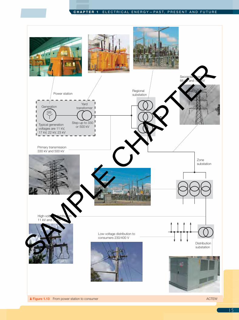
franchise area. The general principles of transmission and
distribution are illustrated in Figure 1.13.
Control of the power system is effected by transmission
network operator control centres in each state, in which
computer-based facilities continuously monitor energy
needs and system stability in communication with
distributor and generator control centres. As consumers
switch on electrical loads, for example, lighting or electrical
machines, more energy is drawn from the system, and less
energy is needed as electrical loads are switched off. In this
way consumers actually determine the amount of energy
the system needs to supply at any point in time. These
changes in energy demand cause instability in the system,
and any change in phase relationship or fl uctuation in
voltage and frequency must be controlled by the network
operators within the limits set down by the Australian
Energy Regulator. Voltages above or below limits specifi ed
by the energy regulator can cause electrical devices to
overheat. Correct supply frequency is important to
prevent damage to generators and to consumers’ electrical
machinery and to maintain the accuracy of electric clocks
and other timing devices.
As you can see, lines of communication in the control of
the power network are of paramount importance. Most large
power network operators have their own telecommunication
network, typically a combination of microwave facilities and
fi bre optic cores embedded in transmission line earth wires
Note: The circuit diagrams in this chapter do not show mandatory protection and control devices, as the diagrams are intended to convey general concepts of transmission and distribution.
Figure 1.12 Modern d.c. transmission
HVDC transmission line
+ +
Converter station Converter station
Isolationtransformer
Isolationtransformer
Valve house
Valve house
Network 1HVACtransmission
Network 2HVACtransmission
Power can be controlledto flow in either direction
Some advantages of HVDC transmission:
than HVAC transmission.
1
01 - Pethebridge vol1 7e.indd 1401 - Pethebridge vol1 7e.indd 14 10/9/09 2:23:41 PM10/9/09 2:23:41 PM
SAMPLE C
HAPTER
15
C H A P T E R 1 E L E C T R I C A L E N E R G Y — P A S T , P R E S E N T A N D F U T U R E
Generation
Typical generation voltages are 11 kV, 17 kV, 22 kV, 23 kV
GS
Yardtransformer
Power station
Primary transmission 330 kV and 500 kV
Regionalsubstation
Secondary transmission66 kV and 132 kV
High-voltage distribution11 kV and 33 kV
Zonesubstation
Distributionsubstation
Low-voltage distribution to consumers 230/400 V
Step-up to 330 or 500 kV
Figure 1.13 From power station to consumer ACTEW
5
01 - Pethebridge vol1 7e.indd 1501 - Pethebridge vol1 7e.indd 15 10/9/09 2:23:42 PM10/9/09 2:23:42 PM
SAMPLE C
HAPTER

E L E C T R I C A L W I R I N G P R A C T I C E — V O L U M E 1
16
(Chapter 4 includes an example of this type of cable.)
Spare communication capacity is generally made available
for leasing by other licensed telecommunication operators.
1.5 Distribution of electricity to consumers The generation and transmission systems bring electricity
supply to the point of fi nal distribution. The low-voltage
distribution system is the second-last link in the chain
joining the power station generator to the consuming device
on the consumer’s premises. The last link is the wiring
within the premises themselves.
Figure 1.14A shows that the fi nal distribution of power is
accomplished by high-voltage feeders that either:
• go directly to bulk supply consumers, who have their
own substation and facilities for low-voltage distribution
on their premises
• go to a number of consumers fed from a common low-
voltage network supplied by distribution transformers
situated at strategic positions throughout the network.
The low-voltage supply to the consumer depends on the
type and rating of the load to be connected, and may be a:
• 230 V two-wire supply (one active conductor and one
neutral), most common for single domestic dwellings
• 230/400 V three-wire supply (two active conductors and
one neutral) where the single-phase demand is higher or
single-phase 400 V equipment, such as a welder, is installed
• 230/400 V four-wire supply (three active conductors
and one neutral) where the demand is highest or where
three-phase loads such as motors are installed. The
single-phase loads must be balanced across the three
phases.
A single-phase three-wire 230/460 V a.c. system is in
current use for isolated supplies, usually in remote rural
districts. The system is known as the single-wire earth-return
(SWER) as transformer primary is supplied by a single wire,
the return being via the general mass of earth, and is typical
of that shown in Figure 1.14b. Supply of 230 V is available for
standard single-phase 230 V light and power loads, whereas
for heavy loads such as welders and large motors, a 460 V
single-phase supply is available.
The three-phase four-wire low-voltage distribution in
which the fourth conductor has the combined function of
The most common standards for low-voltage supply system are:Type: Three-phase four-wire (TN-C)Nominal voltages: 230/400 V a.c.* Tolerance Australia: +10% to –6% at 50 Hz Tolerance New Zealand: ± 6% at 50 Hz.* The agreed supply from some distributors may maintain the previous standard of 240/415 V ± 6%
Protective Earth and Neutral conductor—you will learn more about this in Chapter 8 Protection—earthing and other protective methods
3 3
3
3
3
3 Typical local area distribution substation
400 V
400 V 400 V
230 V
Consumers 1 and 2:230 V two-wire
Consumer 3:230/400 Vthree-wire
Consumer 4:230/400 Vfour-wire
1 2 34
High-voltage customers
Low-voltage customers
Step-down transformer 11 kV to 230/400 V
Step-down transformer 11 to 230/400 V
Step-down transformer 11 to 230/400 V
L1
L2
L3
PEN
11 kV 3-phase supply
Figure 1.14a Distribution to urban consumers
1
01 - Pethebridge vol1 7e.indd 1601 - Pethebridge vol1 7e.indd 16 10/9/09 2:23:44 PM10/9/09 2:23:44 PM
SAMPLE C
HAPTER

17
C H A P T E R 1 E L E C T R I C A L E N E R G Y — P A S T , P R E S E N T A N D F U T U R E
protective earth and neutral, as described in this section, is
by far the most commonly used system throughout Australia
and New Zealand and is the system referred to in Part 2 of
the Wiring Rules.
1.6 Distribution of electricity in the consumer’s installation
Safety and effi ciency are the prime considerations in
the electrical generation, transmission and distribution
systems discussed in this chapter. In the fi nal step of
delivering electricity for use in lighting and appliances,
that is, the consumer’s own electrical installation, safety is
paramount. All electrical installations must comply with
the fundamental safety requirements of the Wiring Rules.
Electricity safety regulations in all jurisdictions require a
process to be followed for obtaining connection of supply
to a consumer installation, and for inspection and testing
to ensure that the installation complies with all safety
requirements of the Wiring Rules and any additional local
service and installation rules. You will learn more about
the safety aspects of electrical installations in subsequent
chapters and as you progress in your training. For now,
to complete the picture of electricity distribution from
generator to use, you need to gain an understanding of the
basic concepts that determine how electricity is distributed
within the electrical installation.
The Wiring Rules require that an electrical installation be
divided into circuits, with devices for control and protection
against faults and over-current. Basic arrangements for a
small and larger installation are shown in Figure 1.15.
An important difference between the low-voltage
distribution supply to the consumer and the consumer’s
installation is that the protective-earth and neutral (PEN)
conductor of the distribution system is divided in the
consumer’s installation into separate protective-earth (PE)
conductors and neutral (N) conductors. You will learn
more about this in Chapter 8.
Connection of the completed and tested installation
to the local distributor’s mains is the fi nal step in getting
a supply of electricity to the consumer’s premises. Forms
to request supply are provided by various electricity
distributors for completion by the electrical contractor or
customer, and they are basically similar but may differ in
detail and layout.
LV earth
33 kV 19.1 kV
A
A
N
Residence230 V two-wire
Farm shed230 V two-wire
Farm plant/machinery230/460 V three-wire
HT andcore earth
19.1 kV SWER line to other customers
SWERdistributiontransformer
Isolationtransformer
Three-phase33 kV line
460 V 230 V
230 V
Typical rural consumer
Single Wire Earth Return (SWER) systemBecause of the simplicity and low cost of the SWER system, it is popular in rural areas where loads are light and consumers few. It is not suitable for urban areas. The two main working problems of the system are in maintaining the effectiveness of the earth-return circuit and in minimising interference with communication circuits.
Earth-return currentsconfined to SWER system
Figure 1.14b Distribution to rural or remote consumers
7
01 - Pethebridge vol1 7e.indd 1701 - Pethebridge vol1 7e.indd 17 10/9/09 2:23:45 PM10/9/09 2:23:45 PM
SAMPLE C
HAPTER

18
E L E C T R I C A L W I R I N G P R A C T I C E — V O L U M E 1
Getting connected to the supply networkElectrical work, whether a new installation or alterations
and additions to existing installations, requires cooperation
between the consumer, the distributor and the electrical
contractor. To this end distributors and electrical regulatory
authorities have processes in place that must be followed to
ensure the network’s quality of service to all consumers and
the safety of the service and electrical installations. Across
most jurisdictions the process for connecting an electrical
installation to the supply network is much the same and this
is outlined in the following points.
Notifi cation of intention to carry out electrical work Well before supply is given and prior to the installation of
wiring, it is necessary to submit an application for supply, or
notice of intention to carry out electrical installation work,
to the local energy distributor. This notifi cation should be
completed in detail and signed by the consumer or electrical
contractor, and applies to work that requires a change to the
load or type of supply.
The main purpose of a notifi cation is to inform the
distributor of the extent of work so that they can make
arrangements to ensure they have the capacity and the
infrastructure to supply electricity to their customers. The
technical information typically provided in a notifi cation is
listed in Table 1.3.
Financial contributionThe distributor may require a fi nancial contribution by a
customer or developer of installations or projects if these
require major alterations or upgrading of supply network
infrastructure in order to supply electricity to customers.
Even in relatively modest installations, such as a single house,
Figure 1.15 Examples of the typical arrangement of consumer installations
PEN
L1
L2
L3
Neutralbar
Earth bar
Active conductors
Circuits for light, power and appliance
Mainswitchboard
Protection andcontrol devices
Service protection devices and metering
Protectiveearthingconductors
Neutralconductors
Typical distribution arrangement of a consumer’s installation with demand less than 100 A per phase
Earth bar
Neutralbar
1
1
4
4
Protection andcontrol devices
Protection andcontrol devices
Service protection devices and metering
Earth bar
Neutralbar
Mainswitchboard
Distribution board
32 22 2 3
Single and three-phase circuitsto light, power and appliance
322 2 3
Single and three-phase circuits to light, power and appliance
Protective earthingconductors
Protective earthingconductors
Typical distribution arrangement of a consumer’s installation with demand greater than 100 A per phase
Note: The PEN conductor of the supply divides into separate protective earth and neutral conductors at the MEN* link mostly at the main switchboard.
* Multiple Earthed Neutral
The number on a single line shows that the line represents that many conductors,
e.g. represents 4 conductors, three phases and neutral.
4
Low-voltage distribution system
1
01 - Pethebridge vol1 7e.indd 1801 - Pethebridge vol1 7e.indd 18 10/9/09 2:23:46 PM10/9/09 2:23:46 PM
SAMPLE C
HAPTER

19
C H A P T E R 1 E L E C T R I C A L E N E R G Y — P A S T , P R E S E N T A N D F U T U R E
the fi nal connection from the distributor’s network to the
consumer’s installation comes at a cost to the consumer.
Verifi cation of complianceWhen the electrical installation is complete, the installing
electrical contractor or supervising electrician must:
• visually inspect the work for compliance with the wiring
regulations
• conduct tests in accordance with the Clause 1.8 and
Section 8 of the Wiring Rules and prescribed by local
regulations.
This is to ensure that the installation is safe and operates
as intended (see Chapter 2).
Once the installation has been proven safe and
compliant with the Wiring Rules and local regulations (e.g.
Distributor service and installation rules, Figure 1.16), the
electrical contractor must give the customer a signed formal
document stating the compliance of the installation. The title
of the compliance document may vary, such as certifi cate of
compliance or certifi cate of electrical safety, depending on
jurisdiction; however, their purpose is the same, that is, to
maintain a safe electrical environment and act as a record to
help to ensure electrical installation work is only carried out
by licensed and competent persons. A copy may be given to
the consumer.
Connecting the supplyBefore connecting the supply, the energy distributor must
visually inspect and test the installation. This is generally
confi ned to the consumer’s mains, the main earthing
conductor, the main switchboard and particular types of
installations such as those in hazardous areas (see
Volume 2). However, in some cases the whole installation
might be inspected under the distributor’s regulatory
obligation to conduct a schedule of checks to monitor
the standard of electrical installation work carried out
by electrical contractors and their employees. If the job
is satisfactory, supply is connected. In some jurisdictions
licensed registered independent inspectors are engaged to
carry out inspection work.
Table 1.3 Typical information supplied in a notifi cation to carry out electrical installation work
Type of installation Whether the installation is new, an alteration to an existing installation or separation of existing supply for multiple customers or tariffs.
Service connection Whether the service is underground, overhead or a combination of both and/or connected directly to a pole-mounted transformer.
Service size Whether the installation requires 100 A, 200 A, 300 A, 400 A or a specifi ed greater rating.
Number of installations Whether this is for a single installation or multiple installation. For a multiple installation list the number of houses or units involved.
Premises type Whether the premises are commercial or domestic or a combination of both.
Maximum demand Current demand determined for each phase of the supply.
Other aspects Estimated length of the service.Whether high-voltage supply is required.Whether proposed equipment may cause excessive voltage fl uctuation (e.g. welders).Whether the installation includes a generator or other alternative source.
Typical content
Typicalal contontent
Typical content
Distributor Service and
Installation Rules
Wiring Rules
Figure 1.16 Distributor service and installation rules
9
01 - Pethebridge vol1 7e.indd 1901 - Pethebridge vol1 7e.indd 19 10/9/09 2:23:47 PM10/9/09 2:23:47 PM
SAMPLE C
HAPTER

E L E C T R I C A L W I R I N G P R A C T I C E — V O L U M E 1
20
Summary
In some areas an electrical contractor may gain
authorisation status to carry out the connection of supply,
and seal service and metering equipment to prevent illegal
tampering with the supply. In this case, the contractor
must be specially trained and carry specifi c safety and test
equipment for the work.
Dealing with defective workIf an installation does not comply with all the tests or rules
or is incomplete the energy distributor has the right to
refuse supply. If the defect on the installation is major, that
is, connecting it to the supply would render the installation
potentially dangerous, the distributor will not connect the
installation. On the other hand, if the defect is considered
to be a minor one, supply is usually given. In either case,
the installation inspector issues a defect notice to the
customer listing the defects of the installation, and the
electrical contractor must remedy the defects and arrange
for a reinspection. Disciplinary action against electrical
contractors for breach of compliance standards can be
severe, depending on the degree of risk these breaches pose
or the repetition of offences. An offending contractor may
be imposed with more frequent inspections of their work
until they can show work that is consistently free of defects.
More serious offences may attract an infringement notice or
fi ne, a licence suspension or a recommendation to undertake
further training.
Situations requiring special procedures There are also situations in which special procedures must
be followed or arrangements made that alter or supplement
those mentioned above. Examples are:
• where a progress inspection or inspections are necessary,
such as in a large factory or a large building where
sections might be required to operate before the
completion of the whole installation
• in the case of a building service, to give supply to
electrical equipment during building operations
• where additions or alterations require a changeover from
existing metering, switchboard or consumer’s mains
to a new position or arrangement, particularly where
minimum disruption of supply is required
• where there is an emergency or breakdown or the
circumstances are such that the usual procedures would
not provide the services required to meet the situation.
E L E C T R I C A L W I R I N G P R A C T I C E — V O L U M E 1
1.1 A brief history of electrical energy production and supply
Discoveries and development of electrical energy,
Table 1.1
Brief history of the electricity supply industry, Table 1.2
1.2 Modern generation methods
Figures 1.1 to 1.4
1.3 Renewable energy and sustainable energy practices
Renewable energy sources, Figures 1.5 to 1.10
Generating and using energy effi ciently
1.4 Electricity transmission and distribution systems
Figures 1.11 to 1.13
1.5 Distribution of electricity to consumers
Page 16, Figures 1.14a, 1.14b
1.6 Distribution of electricity in the consumer’s installation
Getting connected to the supply network,
Figure 1.15
Notifi cation of intention to carry out electrical
work, Table 1.3
Financial contribution
Verifi cation of compliance, Figure 1.16
Connecting the supply
Dealing with defective work
Situations requiring special procedures
2
01 - Pethebridge vol1 7e.indd 2001 - Pethebridge vol1 7e.indd 20 10/9/09 2:23:49 PM10/9/09 2:23:49 PM
SAMPLE C
HAPTER

21
C H A P T E R 1 E L E C T R I C A L E N E R G Y — P A S T , P R E S E N T A N D F U T U R E
Review questions
1 Who made the most important contribution to the
electrical industry, in your opinion? Give reasons for
your opinion.
2 How does coal-powered thermal generation work?
3 Describe the basic principle of electricity generation in
an alternator.
4 At what voltages do steam turbine driven alternators
produce electricity?
5 How is the steam that is used to drive the turbine
isolated from the reactor in nuclear-powered thermal
generation?
6 How is the thermal effi ciency of a gas turbine alternator
increased?
7 Why is it important to drive a generator at a particular
constant speed?
8 Apart from being a clean energy source, what are some
advantages of hydro generation over steam generation?
9 What is hot rock technology?
10 How can water be reused for power generation in a
hydro scheme?
11 List some common applications of direct solar power
generation.
12 Give an example of effi cient use of energy.
13 What are the advantages of three-phase a.c. systems?
14 What is the main disadvantage of the original d.c.
supply systems?
15 Describe the principles and advantages of modern d.c.
transmission.
16 How are the conductors in a three-phase low-voltage
system designated?
17 What are the primary and secondary transmission
voltages?
18 What role do substations play in the transmission and
distribution of electricity?
19 Who determines how much energy is needed from the
electricity supply system at any one time?
20 What is the most common distribution system to
consumers in Australia and New Zealand?
21 Explain the function of the fourth conductor in the
three-phase low-voltage distribution system.
22 Illustrate a SWER system showing the typical voltages it
supplies.
23 List the confi gurations of low-voltage supply to
consumers.
24 How is the protective earth and neutral (PEN)
conductor arranged in the consumer’s installation?
25 Describe the Wiring Rules requirement for arrangement
of electrical installations.
26 List the components of a consumer’s installation that
are installed at a main switchboard.
27 Briefl y describe the main processes involved in
connecting supply to a consumer’s installation.
28 What actions are taken if an inspector fi nds an
installation to be defective?
29 Name three aspects of electrical work typically covered
in service and installation rules.
30 Describe a situation where special procedures are used
for inspection and connection or disconnection of
supply.
01 - Pethebridge vol1 7e.indd 2101 - Pethebridge vol1 7e.indd 21 10/9/09 2:23:50 PM10/9/09 2:23:50 PM
SAMPLE C
HAPTER