Embed Size (px)
Citation preview
LEARN
ING
ACTIVITY #2
Test the Strength of Structural Members
Learning Activity #2:
Overview of the ActivityIn this learning activity, we will test the strengths of the cardboard structural members we used in our
model of the Grant Road Bridge. We will design a series of experiments to determine the strengths of these members in both tension and compression. The experiments will be conducted with a simple testing machine that uses a lever to apply a controlled force to a test specimen. 1
To analyze the experimental data obtained from the testing machine, we will learn and apply the principle of the lever. Finally, we will use a computer spreadsheet to graph the results of our tests. These graphs will help us to observe how various physical properties affect the strength of a structural member. We will also use these graphs as a tool for analyzing and designing bridges in Learning Activities #3 and #5.
Why?To design a structure, an engineer must be able to determine the strengths of the structural members that
comprise it. In Learning Activity #1, we saw that external loads cause internal forces to develop in a structure. We also observed that a structure can successfully carry its external loads only if the internal member forces are less than the corresponding member strengths. Thus an engineer can’t evaluate the load-carrying ability of the structure without first being able to determine member strengths.
Engineers determine the strengths of members in two different ways—through experimentation and through the application of scientific principles. The scientific study of structural members and materials is called the mechanics of materials. The mechanics of materials is typically taught as an entire undergraduate
2-1
1 It is not intended that students build the testing machine as part of this learning activity. The device is quite simple, but it will require some woodworking skill to build. Detailed drawings and dimensions are provided In Appendix C. One device will be adequate for a class of students; however, one device per four or five students will greatly enhance the opportunities for hands-on participation in the learning activity. Once built, the testing machine can be re-used indefinitely.
#2
2-2
engineering course and thus is beyond the scope of this book. In this learning activity, we will determine member strengths primarily through experimentation. However, by carefully examining trends in our experi-mental data, we will discover some of the fundamental principles on which the mechanics of materials is based.
We will also learn how to design a series of experiments to obtain the data required to solve a problem. The ability to design and conduct experiments is not just important to structural engineers—it is a critical skill in a wide variety of engineering and scientific fields.
Learning ObjectivesAs a result of this learning activity, you will be able to do the following:
n Calculate the cross-sectional area of a structural member.
n Describe the yielding, rupture, and buckling failure modes.
n Explain the factors that affect the tensile strength and the compressive strength of a structural member.
n Design a testing program to determine the strength of structural members.
n Determine the tensile strength and the compressive strength of structural members through experimentation.
n Explain the principle of the lever, and apply this principle to the analysis of experimental data.
n Use a computer spreadsheet to analyze and graph experimental data.
Key TermsTo successfully complete this learning activity, you must understand the following key terms and concepts
from Learning Activity #1:
member load tension strength
force internal force compression failure
Information1. Cross-Section and Cross-Sectional Area
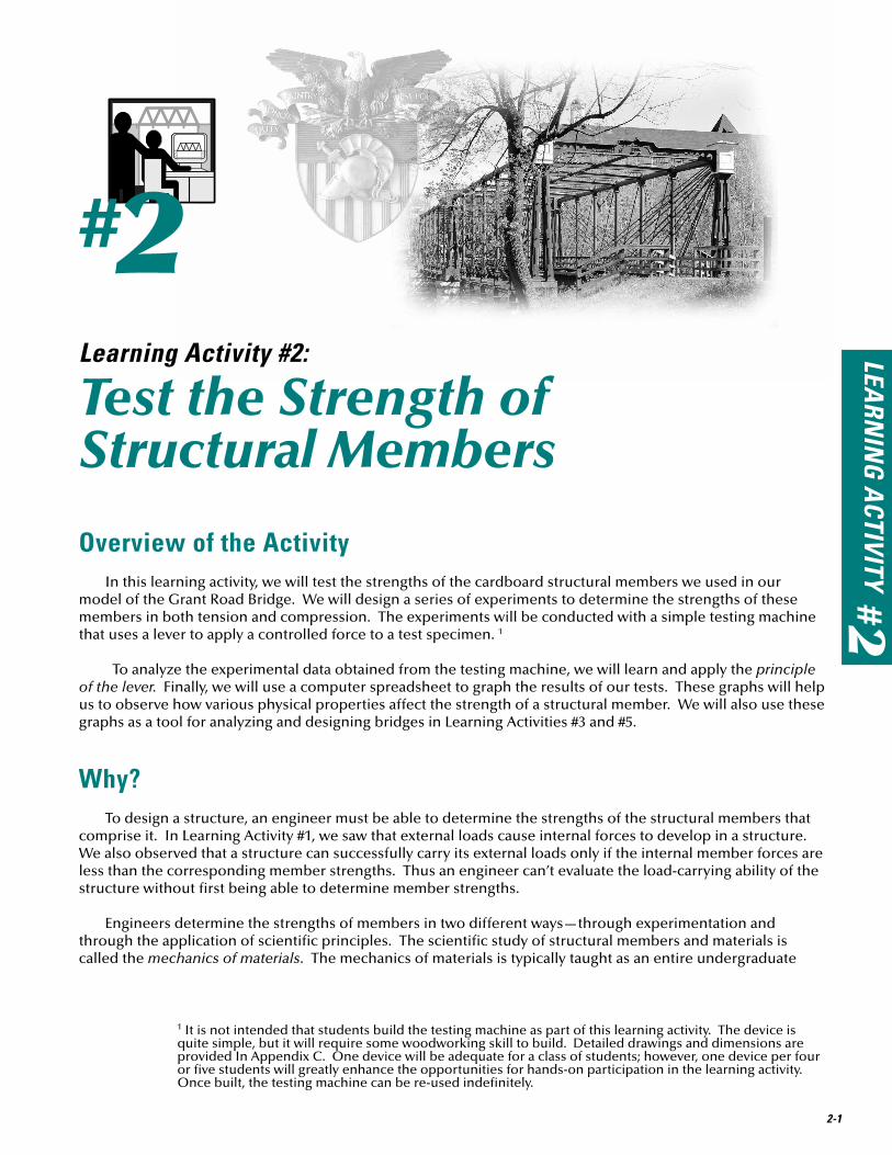
One of the most important characteristics affecting the strength of a structural member is its cross-section. A cross-section is the two-dimensional shape you see when you look at the end of a member. In the illustration below, for example, the solid rod has a circular cross-section, and the solid bar has a rectangular cross-section.
Cross-Sectionw
h
Typical Structural Members
w
h
Solid RodSolid Bar
Hollow Tube
Shape
Solid Rod Solid Bar Hollow Tube Shape
Typical structural members and their cross-sections.

LEARN
ING
ACTIVITY #2
2-3
The cross-sectional area is the surface area of the cross-section. For example, the cross-sectional area of the solid bar on the previous page is the area of the black rectangle. To calculate it, you would multiply the width w by the height h. The cross-sectional area is always expressed in units of length squared—for example, square inches or square millimeters.
2. Tensile Strength
In Learning Activity #1, we defined strength as the maximum internal force a member can carry before it fails. The internal force in a structural member can be either tension or compression. Because the failure of a structural member in tension is very different from its failure in compression, we must consider the tensile strength and compressive strength separately.
Tensile strength is the maximum tension force a member can carry before it fails. As this definition suggests, one way to determine the tensile strength of a member is to load it in tension until it fails—that is, pull on the member from both ends until it physically breaks in two—then mea-sure the amount of force that caused the failure.
Suppose we wanted to test the tensile strength of a carbon steel bar. Carbon steel is one of the most common materials used in structures. It is a mixture of iron and a very small amount of carbon—less than 1%. For our carbon steel test specimen, we will use the bar shown here. It has a square cross-section measuring 1 inch on each side. This cross-section is typically designated 1” x 1” (“one inch by one inch”), and its cross-sectional area is 1 square inch.
Steel is quite strong. To break a steel bar—even this rela-tively small one—we will need a special machine like the one pictured below. This hydraulic testing machine is capable of stretching a test specimen with many thousands of pounds. The machine can measure both the load on the specimen and its corresponding deformation—the increase in the length of the bar as it is stretched.
To determine the tensile strength of a member, pull on it from both ends until it breaks in two.
A hydraulic testing machine.
To test the bar, we will clamp its ends into the machine and gradually increase the load until the steel fails. As the load is applied, the machine will continuously measure and record both the load and the deformation of the specimen. If we plot these data on a graph, the result will look something like this.
1”
1”
10”

2-4
Load-deformation curve for a 1” x 1” carbon steel bar.
0.012 2.0
10,000
20,000
30,000
40,000
50,000
60,000
Load
(pou
nds)
Deformation (inches)0
0
XYield Point Rupture
Ultimate Strength
Yield Strength
0.012 2.0
10,000
20,000
30,000
40,000
50,000
60,000
Load
(pou
nds)
Deformation (inches)0
0
XYield Point
XYield Point
Ultimate Strength
Yield Strength
Ultimate Strength
Yield Strength
This graph is called a load-deformation curve. It shows us how the member deforms—and ultimately how it fails—as the load is increased. 2 A careful examination of the load-deformation curve will tell us a lot about carbon steel. Let’s examine the curve from left to right. The load-deformation curve originates in the lower left-hand corner of the graph, which tells us that the deformation is zero when the load is zero. This certainly makes sense. The bar won’t start to stretch until we apply a force to it. As we follow the curve up and to the right, we notice that the curve is almost perfectly straight from zero all the way up to about 36,000 pounds. The straight line means that the deformation increases in direct proportion to the load. For example, the deforma-tion at 20,000 pounds is exactly twice as large as the deformation at 10,000 pounds. In this linear part of the load-deformation curve, the behavior of the steel bar is said to be elastic. Elastic behavior means that, if the load is removed, the deformation will also return to zero. When a member is elastic, it always returns to its original length after it is unloaded. This particular steel bar will remain elastic, as long as the load on it is kept below 36,000 pounds. When the load does reach 36,000 pounds, the deformation of the bar is just over 1/100”. The total length of the bar has increased from 10” to 10.012”—a change of only about one tenth of one percent.
As the load is increased beyond 36,000 pounds, the behavior of the bar changes rather abruptly. There is suddenly a huge increase in deformation, with virtually no change in the load. The steel is beginning to fail. When a material undergoes large deformations with little change in load, it is said to be yielding. The point on the load-deformation curve where yielding begins is called the yield point, and the force at which yielding occurs is called the yield strength. Beyond the yield point, the steel stretches like taffy. And unlike the elastic behavior we observed earlier, any deformation that occurs beyond the yield point will not disappear after the load is removed. This permanent elongation of the member is called plastic deformation. Note that, as the plastic deformation increases, the bar eventually begins to carry more load. The load peaks at 58,000 pounds, which is called the ultimate strength of the member. After further plastic deformation, the specimen finally breaks into two pieces. This failure mode is called a rupture.
So what is the tensile strength of this steel member? Is it the yield strength or the ultimate strength? Since the tensile strength is the force at which the member fails, the answer to this question depends on how the structural engineer chooses to define “failure.” For most practical structural applications, the engineer would probably want to ensure that the member does not yield. In such cases, “failure” would be defined as yielding, and the tensile strength would be 36,000 pounds—the yield strength. In some cases, however, the engineer might only want to ensure that the member does not rupture. In such cases, the tensile strength would be 58,000 pounds—the ultimate strength. This latter definition of failure might be appropriate, for example, when the engineer is designing for the effect of an extraordinary event like a major earthquake. In such cases, the engineer might be willing to accept some plastic deformation of the structure, as long as it does not collapse.
2 The test machine measures the load applied to the bar. What we are really interested in, however, is the internal force in the bar. Fortunately, in this test, the magnitude of the load and the internal member force are exactly equal. Can you explain why?

LEARN
ING
ACTIVITY #2
This is an important and often misunderstood point—in structural engineering, there is often no single uni-versally accepted definition of “failure.” Rather, the engineer must exercise his or her professional judgment to determine the conditions under which a structure (or a component of a structure) no longer will function as intended.
One other characteristic of the load-deformation curve for the carbon steel bar is worth mentioning. Note that, at rupture, the bar has deformed two full inches—20% of its original length. This capacity to undergo very large plastic deformation after yielding is called ductility. Ductility is one of the most beneficial properties of steel, and it is one of the most important reasons why steel is so widely used in structures. When a ductile member begins to fail, its large plastic deformation provides an obvious warning that something is wrong with the structure. This warning provides an opportunity to evacuate people and make emergency repairs before the structure collapses. For this reason, ductility greatly enhances structural safety.
Not all structural materials are ductile. Materials that do not undergo large plastic deformation prior to failure are called brittle materials. A typical load-deformation curve for a brittle material is shown at right. Note that the material ruptures with-out yielding and thus without giving any warning that a failure is about to occur. For this reason, brittle materials are generally undesirable for structural members. Cast iron is a brittle material, which explains why cast iron has been entirely replaced by steel in modern structures. Concrete is a brittle material, which explains (in part) why concrete is always reinforced with steel bars when it is used as a structural material.
We have seen how one particular structural member made of one particular material can be tested to determine its tensile strength. If we were to repeat this test with many different members—different sizes, different cross-sections, and different materials—some patterns would begin to emerge. A careful analysis of these patterns would reveal the following facts about the tensile strength of structural members:
n Tensile strength depends on the cross-sectional area of a member. As the cross-sectional area increases, the tensile strength increases in direct proportion to the area. If the cross-section of our carbon steel bar were changed from 1” x 1” to 2” x 2”, the cross sectional area would increase from 1 square inch to 4 square inches, and the yield strength would increase from 36,000 pounds to about 144,000 pounds—four times greater.
n Tensile strength depends on the type of material the member is made of. Every material has its own charac-teristic strength, measured in units of force per area (for example, pounds per square inch or newtons per square meter). The yield strength of carbon steel is 36,000 pounds per square inch. Other types of steel with yield strengths of 50,000 pounds per square inch and higher are common. The tensile strength of a member can be calculated by multiplying the tensile strength of the material by the cross-sectional area of the member.
n Tensile strength does not depend on the length of a member. If we used the same 1” x 1” cross-section but changed the length of our specimen from 10” to 20”, the tensile strength would remain exactly the same.
n Tensile strength does not depend on the shape of the cross-section. If we tested a hollow tube or circular rod with a cross-sectional area of 1 square inch, we would find that its tensile strength is exactly the same as the 1” x 1” square steel bar.
These observations will guide the design of our own testing program, later in this learning activity.
3. Compressive Strength
Compressive strength is the maximum compression force a member can carry before it fails. We can determine the compressive strength of a structural member by loading it in compression until it fails, then
2-5
Load
Deformation0
0
X
Rupture
UltimateStrength
Load
Deformation0
0
X
Rupture
UltimateStrength
Load-deformation curve for a brittle material.
2-6
measuring the amount of force required to cause the failure.
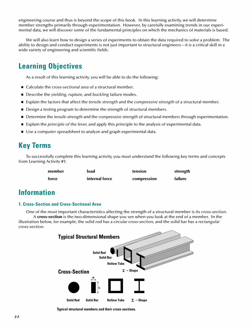
To understand how a structural member fails in compression, try the following simple experiment. Hold a yardstick or meter stick vertically, with its bottom end on the floor. Now put the stick in compression by pushing downward on its top end. Gradually increase the compression force. At some point, the stick will suddenly bend sideways—in engineer-ing terms, it will buckle. Buckling is a failure that occurs when compression causes a member to suddenly bend sideways, perpendicular to the direction of the applied load. Buckling is the most common failure mode for structural members in compression. When a member fails by buckling, its compressive strength is the internal force at which buckling occurs.
Try repeating the same experiment with a 12-inch wooden ruler. Unless you’re really strong, you’ll probably find that you can’t push hard enough on the 12-inch ruler to make it buckle. This observation suggests an important characteristic of buckling failures: Shorter members have greater compressive strength than longer ones.
Now suppose we wanted to test the compressive strength of a 1” x 1” carbon steel bar. Again, we would need to use our hydraulic testing machine to load the bar. It would take about 34,000 pounds of compressive force to cause the 10” long bar to buckle. Recognizing that the compressive strength of the bar depends on its length, we would need to test a series of 1” x 1” square bars, each with a different length. We would find that increasing the length of the bar to 20” would cause a substantial reduction in its strength—to about 28,000 pounds. A 40” bar would fail at around 13,000 pounds. If we tested members with lengths up to 100” and plotted the results on a graph of compressive strength vs. length, the result would look like this:
0
5000
10000
15000
20000
25000
30000
35000
40000
0 20 40 60 80 100
Length (inches)
Com
pres
sive
Str
engt
h (p
ound
s)
Compressive strength vs. length for a 1”x1” carbon steel bar.
This graph vividly illustrates the effect of member length on compressive strength. Note that an 80” member is less than one-tenth as strong as a 10” member, even though their cross-sections are identical.
How do the size and shape of the cross-section affect compressive strength? In Learning Activity #1, we observed that hollow tubes seem to be more effective than solid bars at carrying compression. Let’s test that observation now with another simple experiment. Using the same file-folder cardboard you used to build the Grant Road Bridge, cut out two identical rectangles measuring 5 centimeters wide and 10 centimeters long. Fold one of the two rectangles into a square tube measuring 1cm x 1cm. Glue the edges together as we did when we prefabricated the square tubes in Learning Activity #1. The second rectangle should remain unfolded—a 5cm-wide “bar” with a length of 10cm. We now have two structural members—a bar and a tube. Both are the same length, and both use exactly the same amount of material. Place each one with its ends between your

LEARN
ING
ACTIVITY #2
2-7
thumb and forefinger, and squeeze. You’ll find that the flat rectangular “bar” buckles with only the slightest compressive force. On the other hand, the tube is amazingly strong—almost impossible to buckle with one hand. This simple test clearly demonstrates another important characteristic of buckling failures: A hollow tube has significantly higher compressive strength than a solid bar using the same amount of material.
Now let’s do the same sort of experiment with actual steel structural members. Our goal is to investigate how the cross-sectional area and cross-section shape affect the compressive strength. We can accomplish this goal by testing a series of steel specimens with various areas and shapes, then comparing the results. Since we will be studying the effects of two different variables—cross-sectional area and shape—we will need to design the experiments carefully. It is important that successive tests change only one variable at a time, so we can logically compare the results and determine the effect of each variable.
For example, consider the following five carbon steel test specimens:
A cardboard bar buckles with
only a slight load.
A cardboard tube is amazingly strong in compression
n Specimen A is the same 1” x 1” solid square bar we have been using throughout this learning activity. The test results for this bar will provide a basis for comparison with the other specimens.
n Specimen B is a hollow tube measuring 2.125” x 2.125”. The thickness of the tube walls is 0.125” (1/8”). These dimensions result in a cross-sec-tional area of exactly 1 square inch—the same as Specimen A. Because their cross-sectional areas are equal, we can compare the test results from Specimens A and B to determine the effect of cross-section shape on compressive strength.
n Specimen C is a 0.707” x 0.707” solid bar. These dimensions result in a cross-sectional area of 0.5 square inches—exactly half the area of Specimen A. Since Specimens A and C have the same shape, we can compare the two sets of test results to determine the effect of cross-sectional area on strength.
n Specimen D is a 1” x 0.5” solid bar. Like Specimen C, this bar has a cross-sectional area of 0.5 square inches; however, the cross-section of Specimen D is rectangular, rather than square. Thus we can compare the test results from Specimens C and D to further examine the effect of cross-section shape on strength.
n Specimen E is a 1.35” x 1.35” hollow tube with walls 0.1” thick. Its cross-sectional area is exactly 0.5 square inch. We can compare the test results from Specimens C and E to determine the effect of cross-section shape. We can compare the results from Specimens A and E to determine the effect of cross-sectional area.
Carbon steel test specimens used to determine how cross-sectional
area and shape affect compressive strength.
1”
1”
Length
A
1” Length
0.5”
D
0.707” Length
0.707”
C
2.125”
2.125”0.125”
Length
B
Length0.1”
1.35”
1.35”
E
1”
1”
Length
A1”
1”
Length
A
1” Length
0.5”
D1” Length
0.5”
D
0.707” Length
0.707”
C
0.707” Length
0.707”
C
2.125”
2.125”0.125”
Length
B
2.125”
2.125”0.125”
Length
B
Length0.1”
1.35”
1.35”
E
Length0.1”
1.35”
1.35”
E
2-8
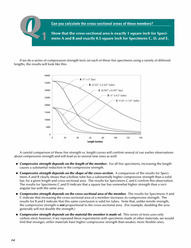
QQ1Can you calculate the cross-sectional areas of these members?
Show that the cross-sectional area is exactly 1 square inch for Speci-mens A and B and exactly 0.5 square inch for Specimens C, D, and E.
If we do a series of compression strength tests on each of these five specimens using a variety of different lengths, the results will look like this:
0
5000
10000
15000
20000
25000
30000
35000
40000
0 20 40 60 80 100 120 140
Length (inches)
B (2.125" x 2.125" tube)
A (1" x 1" bar)
C (0.707" x 0.707" bar)
D (1" x 0.5" tube)
E (1.35" x 1.35" tube)
A careful comparison of these five strength vs. length curves will confirm several of our earlier observations about compressive strength and will lead us to several new ones as well:
n Compressive strength depends on the length of the member. For all five specimens, increasing the length causes a substantial reduction in the compressive strength.
n Compressive strength depends on the shape of the cross-section. A comparison of the results for Speci-mens A and B clearly shows that a hollow tube has a substantially higher compressive strength than a solid bar, for a given length and cross-sectional area. The results for Specimens C and E confirm this observation. The results for Specimens C and D indicate that a square bar has somewhat higher strength than a rect-angular bar with the same area.
n Compressive strength depends on the cross-sectional area of the member. The results for Specimens A and C indicate that increasing the cross-sectional area of a member increases its compressive strength. The results for B and E indicate that this same conclusion is valid for tubes. Note that, unlike tensile strength, the compressive strength is not proportional to the cross-sectional area. (For example, doubling the area generally will not double the strength.)
n Compressive strength depends on the material the member is made of. This series of tests uses only carbon steel; however, if we repeated these experiments with specimens made of other materials, we would find that stronger, stiffer materials have higher compressive strength than weaker, more flexible ones.
LEARN
ING
ACTIVITY #2
2-9
QQ2What can we learn from a comparison of Specimens A and E?
Compare the compressive strength vs. length curves for Specimens A and E on the graph above. What conclusion can you draw from this comparison?
4. The Principle of the Lever
When actual structural members are tested in a laboratory, powerful hydraulic machines are used to per-form the tests. We don’t have hydraulic power available for this project, but we do have the power of the lever to help us apply a large, controlled, measurable tension or compression force to a cardboard structural member. The simple testing machine we will use in this learning activity is based on the prin-ciple of the lever; thus, to understand how the machine works, you will need to understand how a lever works.
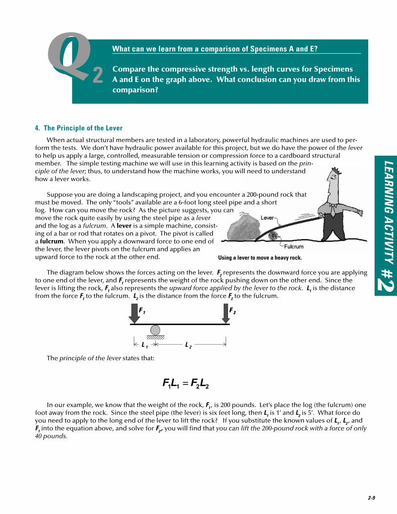
Suppose you are doing a landscaping project, and you encounter a 200-pound rock that must be moved. The only “tools” available are a 6-foot long steel pipe and a short log. How can you move the rock? As the picture suggests, you can move the rock quite easily by using the steel pipe as a lever and the log as a fulcrum. A lever is a simple machine, consist-ing of a bar or rod that rotates on a pivot. The pivot is called a fulcrum. When you apply a downward force to one end of the lever, the lever pivots on the fulcrum and applies an upward force to the rock at the other end.
The diagram below shows the forces acting on the lever. F2 represents the downward force you are applying to one end of the lever, and F1 represents the weight of the rock pushing down on the other end. Since the lever is lifting the rock, F1 also represents the upward force applied by the lever to the rock. L1 is the distance from the force F1 to the fulcrum. L2 is the distance from the force F2 to the fulcrum.
The principle of the lever states that:
In our example, we know that the weight of the rock, F1 , is 200 pounds. Let’s place the log (the fulcrum) one foot away from the rock. Since the steel pipe (the lever) is six feet long, then L1 is 1’ and L2 is 5’. What force do you need to apply to the long end of the lever to lift the rock? If you substitute the known values of L1 , L2 , and F1 into the equation above, and solve for F2 , you will find that you can lift the 200-pound rock with a force of only 40 pounds.
Using a lever to move a heavy rock.
L 1 L 2
F 2F 1
L 1 L 2
F 2F 1
2-10
QQ3Using this lever, how much weight could you lift with 50 pounds?
Suppose you need to move another rock with this lever. Using the same bar and fulcrum location, you push downward with a force of 50 pounds to lift the rock. How much does the rock weigh?
This simple example shows how a lever can be used to significantly increase the amount of force that can be applied to an object. It also shows how we can use the principle of the lever to precisely calculate the amount of force applied to an object. The testing machine we will be using to conduct strength tests is a direct applica-tion of this principle.
5. Converting Mass to Weight
Weight is a force; thus, we express the weight of an object in units of force. In the lever example above, the weight of the rock and the forces applied to the lever are expressed in pounds—the standard measure of force in the U.S. Customary system of units.
The experiments conducted in this learning activity use metric units, also called SI units. (SI stands for Systeme International.) Determining the weight of an object in SI units is a bit more complicated than doing it in U.S. units. When you “weigh” an object on a metric scale, the number you read from the scale is usually in grams or kilograms, which are units of mass, not force. Thus, when you “weigh” an object on a metric scale, you actually do not measure its weight. You measure its mass.
To determine the weight of this object, you must convert its mass to a force, using the equation
In this equation, W is the weight of the object, m is its mass, and g is the acceleration of gravity. In SI units, g = 9.81 meters/sec2. If you express the mass m in kilograms, then the weight W will be in newtons.
QQ4What is the weight of a 5-kilogram mass?
In Learning Activity #1, we used a 5-kilogram stack of books to load the Grant Road Bridge. How much did this stack of books weigh?
We will use this mass-to-weight conversion extensively when we analyze the experimental data collected as part of this learning activity.

LEARN
ING
ACTIVITY #2
2-11
The Problem
The NeedThe Town Engineer of Hauptville, New York, has decided to conduct a structural evaluation of the Grant
Road Bridge, to ensure that it can safely carry the required highway loads. Before he can begin analyzing the structure, he will need to obtain information about the strengths of the various structural members used in the main trusses. He decides to hire a materials testing laboratory to design and conduct an experimental testing program to provide the necessary information.
Your JobYour materials testing company, Universal Structural Materials Assessment, Inc., has been hired by the
Hauptville Town Engineer to provide experimental data in support of his structural evaluation of the Grant Road Bridge. Your job is to design and conduct a program of experimentation to determine the strengths of all structural members used in the main trusses of the bridge. As a technical specialist, you are responsible for providing your client with complete, accurate data and presenting that data in a manner that is both under-standable and usable.
The Solution
The PlanOur plan to provide the Hauptville Engineer with the information he needs is as follows:
n Familiarize with the testing machine that we will use for our experiments.
n Design a testing program.
n Make the test specimens.
n Conduct tension and compression strength tests.
n Analyze and graph the experimental data.
The product of our work will be a series of graphs that the Hauptville Engineer can use as the basis for his structural evaluation.
The Testing Machine
DescriptionThis simple lever-based testing machine will allow you to apply a controlled tension or compression force to
a test specimen and measure that force with reasonable accuracy. Though you do not need to build the machine, you should understand how it works, in order to use it properly and to achieve accurate results.
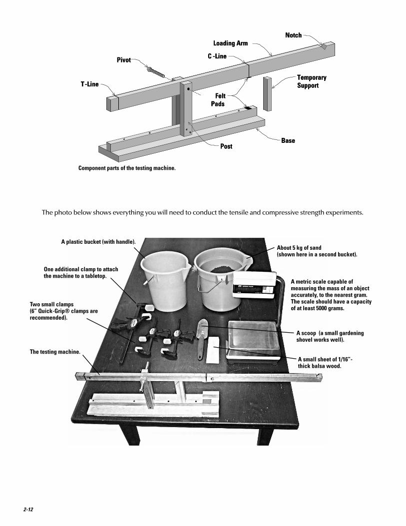
The configuration and component parts of the testing machine are illustrated in the drawing below. The loading arm is fastened to the posts with a steel bolt, which serves as a pivot. The T-Line and C-Line are vertical marks on the loading arm, indicating the points where the tension and compression specimens will be fastened for testing. Felt pads are fastened to the underside of the loading arm and the top side of the base at the C-Line. These pads will ensure that compression test specimens are uniformly loaded. The temporary support is a wooden post that is used to support the loading arm while a tension specimen is being clamped into position.
The Learning Activity
2-12
Component parts of the testing machine.
The photo below shows everything you will need to conduct the tensile and compressive strength experiments.
Pivot
Loading ArmNotch
TemporarySupport
BasePost
C -Line
T-Line
FeltPads
Pivot
Loading ArmNotch
TemporarySupport
BasePost
C -Line
T-Line
FeltPads
The testing machine.
Two small clamps (6” Quick-Grip® clamps are recommended).
One additional clamp to attach the machine to a tabletop.
A plastic bucket (with handle).About 5 kg of sand (shown here in a second bucket).
A scoop (a small gardening shovel works well).
A metric scale capable of measuring the mass of an object accurately, to the nearest gram. The scale should have a capacity of at least 5000 grams.
A small sheet of 1/16”- thick balsa wood.
LEARN
ING
ACTIVITY #2
2-13
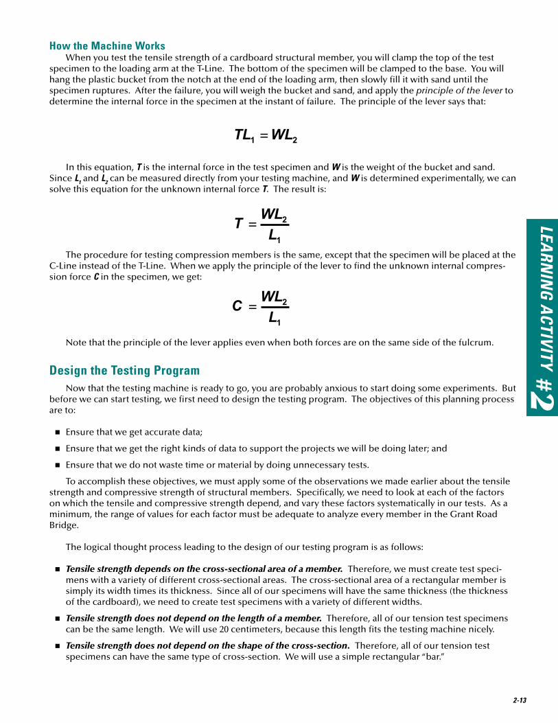
How the Machine WorksWhen you test the tensile strength of a cardboard structural member, you will clamp the top of the test
specimen to the loading arm at the T-Line. The bottom of the specimen will be clamped to the base. You will hang the plastic bucket from the notch at the end of the loading arm, then slowly fill it with sand until the specimen ruptures. After the failure, you will weigh the bucket and sand, and apply the principle of the lever to determine the internal force in the specimen at the instant of failure. The principle of the lever says that:
In this equation, T is the internal force in the test specimen and W is the weight of the bucket and sand. Since L1 and L2 can be measured directly from your testing machine, and W is determined experimentally, we can solve this equation for the unknown internal force T. The result is:
The procedure for testing compression members is the same, except that the specimen will be placed at the C-Line instead of the T-Line. When we apply the principle of the lever to find the unknown internal compres-sion force C in the specimen, we get:
Note that the principle of the lever applies even when both forces are on the same side of the fulcrum.
Design the Testing ProgramNow that the testing machine is ready to go, you are probably anxious to start doing some experiments. But
before we can start testing, we first need to design the testing program. The objectives of this planning process are to:
n Ensure that we get accurate data;
n Ensure that we get the right kinds of data to support the projects we will be doing later; and
n Ensure that we do not waste time or material by doing unnecessary tests.
To accomplish these objectives, we must apply some of the observations we made earlier about the tensile strength and compressive strength of structural members. Specifically, we need to look at each of the factors on which the tensile and compressive strength depend, and vary these factors systematically in our tests. As a minimum, the range of values for each factor must be adequate to analyze every member in the Grant Road Bridge.
The logical thought process leading to the design of our testing program is as follows:
n Tensile strength depends on the cross-sectional area of a member. Therefore, we must create test speci-mens with a variety of different cross-sectional areas. The cross-sectional area of a rectangular member is simply its width times its thickness. Since all of our specimens will have the same thickness (the thickness of the cardboard), we need to create test specimens with a variety of different widths.
n Tensile strength does not depend on the length of a member. Therefore, all of our tension test specimens can be the same length. We will use 20 centimeters, because this length fits the testing machine nicely.
n Tensile strength does not depend on the shape of the cross-section. Therefore, all of our tension test specimens can have the same type of cross-section. We will use a simple rectangular “bar.”

2-14
3 cm
20 cm
3 cm
width3 cm
20 cm
3 cm
width
n Compressive strength depends of the shape and size of the cross-section. Therefore, we must create compression test specimens for each of the different cross-sections we plan to use in our structure. We will test rectangular tubes with the same dimensions as the tubes used in the Grant Road Bridge model.
n Compressive strength depends of the length of the member. Therefore, we must create test specimens with the full range of different lengths we plan to use in our structure. We will use lengths from 5 to 16 centimeters.
n Tensile and compressive strength both depend on the material the member is made of. Therefore, to do a truly comprehensive testing program, we would need to create test specimens of various different materi-als. Since our projects will all use the same type of cardboard, however, we will only test this one material.
In designing the testing program, we must also consider the effects of experimental error and the natural variability of the properties we are attempting to measure. There are many possible sources of experimental error in our test setup. (We will discuss them in detail later.) Some of these can be controlled by conducting the tests very carefully; but no matter how careful we are, our experimental data will exhibit some natural variability. For this reason, we should repeat each of our experiments several times and average the results. Repeating each experiment several times is especially important for the compression tests, which are inherently more variable than the tension tests.
Taking all of these factors into account, our testing program will consist of the following experiments:
Make the Test SpecimensThe configuration of a typical tension test specimen is shown below. The member itself is a strip of card-
board 20 centimeters long, sliced from a file folder just as we did in Learning Activity #1. Glued onto each end of the member is a 3-centimeter square of cardboard, which provides a surface for the clamps to grip when the specimen is placed in the testing machine.
Test #
Cross-Section Length Number of Specimens
T1 4 mm-wide bar 20 cm 3 T2 6 mm-wide bar 20 cm 3 T3 8 mm-wide bar 20 cm 3 C1 10 mm x 10 mm tube 5 cm 3 C2 10 mm x 10 mm tube 10 cm 3 C3 10 mm x 10 mm tube 16 cm 3 C4 6 mm x 10 mm tube 5 cm 3 C5 6 mm x 10 mm tube 10 cm 3 C6 6 mm x 10 mm tube 16 cm 3
Tension test specimen.
LEARN
ING
ACTIVITY #2
2-15
Making a tension test specimen.
Reinforcing the ends of a compression test specimen.
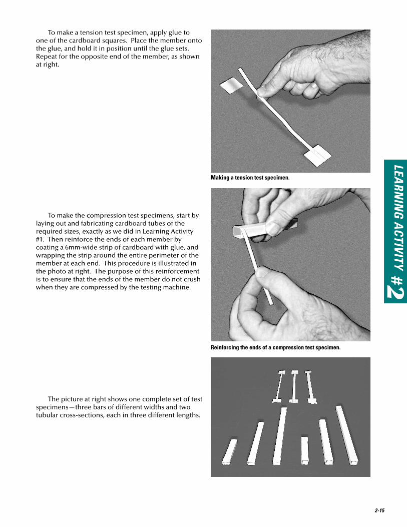
To make a tension test specimen, apply glue to one of the cardboard squares. Place the member onto the glue, and hold it in position until the glue sets. Repeat for the opposite end of the member, as shown at right.
To make the compression test specimens, start by laying out and fabricating cardboard tubes of the required sizes, exactly as we did in Learning Activity #1. Then reinforce the ends of each member by coating a 6mm-wide strip of cardboard with glue, and wrapping the strip around the entire perimeter of the member at each end. This procedure is illustrated in the photo at right. The purpose of this reinforcement is to ensure that the ends of the member do not crush when they are compressed by the testing machine.
The picture at right shows one complete set of test specimens—three bars of different widths and two tubular cross-sections, each in three different lengths.

2-16
Conduct the Tension TestsUse the following procedure to test each of your
tension specimens:
1) To prepare for your first test, clamp the testing machine to the edge of a table, with the long end of the loading arm overhanging as shown. Place the temporary support under the loading arm, and hang a bucket from the notch at the end of the loading arm. Put a chair or stool below the bucket and, if necessary, stack books on the chair so that the space between the top of the stack and the bottom of the bucket is only about two inches. When a test specimen breaks, the bucket will fall; we don’t want it to fall very far.
2) Place one of the 4mm tension specimens (Test T1) into position, centered on the T-Line.
3) Clamp the top of the specimen to the loading arm and the bottom of the specimen to the base. Ensure that the specimen remains straight and vertical. The clamps must be tight, so the speci-men won’t slip.
2
3
1

LEARN
ING
ACTIVITY #2
2-17
QQ5Is cardboard ductile or brittle?
Did your test specimen fail in a ductile or brittle manner? What does this characteristic tell you about the suitability of cardboard as a structural material?
4) Remove the temporary support, and gently allow the weight of the bucket to pull the specimen tight. Now begin the loading process. Fill the scoop with sand, then slowly pour the sand from the scoop into the bucket. Wait 5 seconds, then add a second scoop of sand. Wait 5 seconds, and add a third scoop. Continue this process, always waiting 5 seconds between scoops, until the specimen breaks.
5) The failure of the specimen will happen suddenly, without warning—often during one of the 5-sec-ond pauses in the loading process. However, if the failure does occur while you are adding sand, stop immediately. The sand in the bucket should be the exact amount that caused the failure to occur.
4
5
6) Lift the bucket off of the testing machine, place it on the scale, and record the mass.
Now empty the bucket, and repeat the process for each of your tension specimens. For each test, keep careful records of the specimen size and the mass of the bucket and sand. 6
2-18
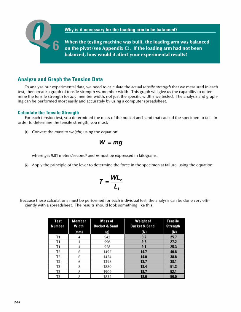
QQ6Why is it necessary for the loading arm to be balanced?
When the testing machine was built, the loading arm was balanced on the pivot (see Appendix C). If the loading arm had not been balanced, how would it affect your experimental results?
Analyze and Graph the Tension DataTo analyze our experimental data, we need to calculate the actual tensile strength that we measured in each
test, then create a graph of tensile strength vs. member width. This graph will give us the capability to deter-mine the tensile strength for any member width, not just the specific widths we tested. The analysis and graph-ing can be performed most easily and accurately by using a computer spreadsheet.
Calculate the Tensile StrengthFor each tension test, you determined the mass of the bucket and sand that caused the specimen to fail. In
order to determine the tensile strength, you must:
(1) Convert the mass to weight, using the equation:
where g is 9.81 meters/second2 and m must be expressed in kilograms.
(2) Apply the principle of the lever to determine the force in the specimen at failure, using the equation:
Because these calculations must be performed for each individual test, the analysis can be done very effi-ciently with a spreadsheet. The results should look something like this:
Test Member Mass of Weight of Tensile Number Width Bucket & Sand Bucket & Sand Strength
(mm) (g) (N) (N)T1 4 942 9.2 25.7T1 4 996 9.8 27.2T1 4 928 9.1 25.3T2 6 1497 14.7 40.8T2 6 1424 14.0 38.8T2 6 1398 13.7 38.1T3 8 1880 18.4 51.3T3 8 1909 18.7 52.1T3 8 1832 18.0 50.0

LEARN
ING
ACTIVITY #2
2-19
In this spreadsheet, the black cells are headings, the white cells are for entry of experimental data, and the gray cells are calculated automatically. The cell formulas required to create this spreadsheet with Microsoft Excel look like this:
Note that the spreadsheet is set up to allow any values of L1 and L2 to be entered. This is important, because the actual measurements L1 and L2 for your testing machine are likely to be different from these values. Note also that the mass was recorded in grams, so it had to be converted to kilograms (divided by 1000) as part of the weight calculation.
QQ7Can you verify these spreadsheet calculations?
Whenever you use a computer to solve a numerical problem, you should verify that the calculations are being done correctly. One way to verify computer results is to perform one complete set of calcula-tions by hand and compare your answer with the one the computer calculated. Select any one of the tension test results above, calculate the tensile strength by hand, and compare your results to the com-puter solution. Are the computer results correct?
Create a Graph of Tensile Strength vs. Member WidthOnce the spreadsheet is set up, it is a relatively simple task to create a graph of tensile strength vs. member
width. The best type of graph for this type of data is an “x-y scatter plot,” with no line connecting the data points. Use member width for the x-axis and tensile strength for the y-axis. The procedure for creating this graph depends of the spreadsheet software you are using. Check the program’s “Help” menu for instructions. The result should look something like the graph on the following page . Each “+” symbol represents one test.

2-20
Tensile Strength vs. Member Length for cardboard members (experimental data).
0
10
20
30
40
50
60
0 1 2 3 4 5 6 7 8 9
Member Width (mm)
Tens
ile S
treng
th (n
ewto
ns)
0.0
10.0
20.0
30.0
40.0
50.0
60.0
0 1 2 3 4 5 6 7 8 9
Member Width (mm)
Tens
ile S
treng
th (n
ewto
ns)
Trend Line
Tensile Strength vs. Member Length for cardboard members (experimental data with trend line).
As you might expect, there is some “scatter” in our experimental data—a clear indication of both experi-mental error and natural variability in the tensile strength of a material. Nonetheless, the data points all appear to lie along a straight line. This observation suggests that there is a linear relationship between member width and tensile strength. We can represent this linear relationship by drawing a “best fit” straight line directly on the x-y scatter plot. Many spreadsheet programs can do this automatically, using a function called “trend line” or “linear regression.” Again, check the “Help” menu of your spreadsheet program to see if either of these functions is available. If not, you can print a copy of the graph you just created, then use a pencil and ruler to draw a straight line that best fits your data. Whether you draw the line yourself or use the spreadsheet to do it, you must ensure that the trend line passes through the point (0,0). We know that a member with zero width must have zero strength, so the point (0,0) must lie on the trend line. In a spreadsheet program, this is normally accomplished by setting the y-intercept of the trend line to zero. The result should look like this:

LEARN
ING
ACTIVITY #2
2-21
Notice that this chart can be used as a powerful design tool. Even though you only performed tests on specimens of three different widths, you can now easily determine the tensile strength of a member with any width between 0 and 8 mm. To use the correct mathematical term, you can interpolate any point on the graph. You could also guess at the strength of a member with a width larger than 8 mm; in other words, you could extrapolate from the graph. But be careful! Extrapolation can be dangerous. Just because our data appear to be highly linear in the range from 0 to 8 mm doesn’t mean that the relationship between member width and tensile strength will continue to be linear for larger widths.
QQ8Can you use the graph to determine tensile strength?
What is the tensile strength of a cardboard member 5 millimeters wide? What is the strength of a double 4-millimeter bar, like the ones we used in the Grant Road Bridge model?
On an Actual Bridge Project
How do engineers obtain data from experimental strength testing?
The sort of strength testing we have been doing in this learning
activity is generally not performed as part of the design process for individual
structures. Rather, testing is done by researchers in universities, in government
laboratories, and in industry. The results of these tests are incorporated into books
called design codes, which are published by professional societies and made avail-
able to engineers. For example, the American Institute of Steel Construction pub-
lishes a design code for steel structures. The American Concrete Institute publishes a
design code for concrete structures. These codes are updated frequently, so that
practicing engineers can have access to the most current research results, without
actually having to develop and conduct experiments for each project.

2-22
Test the Compression Specimens1) To conduct the compression tests, set up the
testing machine in the same way you did for the tension tests. Place one of the 16 cm-long speci-mens (Test C3) at the “C-Line,” between the loading arm and the base. Both the top and bottom of the specimen should be resting on the felt pads.
Once the specimen is in place, apply load just as you did for the tension tests. Add sand to the bucket one scoop at a time, pausing 5 seconds between scoops.
2) When the specimen buckles, remove the bucket, place it on the scale, and record the mass.
Empty the bucket, and repeat the process for each of your compression specimens. For each test, keep careful records of the specimen size and length and the mass of the bucket and sand.
3) To mount the 10cm-long and 5cm-long specimens, a minor adjustment to the testing machine will be required. It is very important that the loading arm be exactly horizontal at the start of each test; otherwise, the four sides of the tube will not be loaded equally. For the shorter specimens, it is necessary to block up the base of the member with books or pieces of wood until the loading arm is level. Use the 16 cm-long temporary support as a gage. Use shims made of 1/16” balsa wood to make fine adjustments to the height of the specimen. Because balsa is soft, these shims will also perform the function of the lower felt pad, which is now covered up.
1
2
3

LEARN
ING
ACTIVITY #2
2-23
QQ9What are some possible sources of error in these experiments?
Now that you have completed the tension and compression tests, think about some of the factors that might cause your results to be inaccurate. List at least five possible sources of experimental error in these tests. Which sources of error do you think have the greatest effect on your results? How can you minimize them?
Analyze and Graph the Compression DataTo analyze our experimental data, we will first calculate the actual compressive strength measured in each
test, then use these data to create a compressive strength vs. length graph for each cross-section. Again, these tasks are best performed with a computer spreadsheet.
Calculate the Compressive StrengthAs long as the distance from the C-Line to the pivot of your testing machine is exactly equal to L1, we can
calculate the compressive strength C using the equation:
We can use a slightly modified version of our tension spreadsheet to do the data analysis. The result should look like this:
Test Size Length Mass of Weight of CompressiveNumber Bucket & Sand Bucket & Sand Strength
(mm) (cm) (g) (N) (N)C1 10 x 10 5 1948 19.1 53.1C1 5 2014 19.8 54.9C1 5 1816 17.8 49.5C2 10 1755 17.2 47.9C2 10 1821 17.9 49.7C2 10 1940 19.0 52.9C3 16 1531 15.0 41.8C3 16 1572 15.4 42.9C3 16 1498 14.7 40.9C4 6 x 10 5 1776 17.4 48.4C4 5 1704 16.7 46.5C4 5 1663 16.3 45.4C5 10 1688 16.6 46.0C5 10 1572 15.4 42.9C5 10 1701 16.7 46.4C6 16 1404 13.8 38.3C6 16 1432 14.0 39.1C6 16 1305 12.8 35.6

2-24
Compressive Strength vs. Length for a 6mm x 10 mm cardboard tube (experimental data).
Compressive Strength vs. Length for a 10mm x 10mm cardboard tube (experimental data).
Create a Graph of Compressive Strength vs. LengthThe compressive strength of a tube is affected by both the size of its cross-section and the length of the
member. Thus we need to create a series of strength vs. length graphs, one for each different cross-section. Again, we will use the “x-y scatter plot,” with member length as the x-axis and compressive strength as the y-axis. The resulting graphs for the 10mm x 10mm and 6mm x 10mm cross-sections should look like this:
0.0
10.0
20.0
30.0
40.0
50.0
60.0
0 2 4 6 8 10 12 14 16 18
Length (cm)
Com
pres
sive
Stre
ngth
(new
tons
)
0.0
10.0
20.0
30.0
40.0
50.0
60.0
0 2 4 6 8 10 12 14 16 18
Length (cm)
Com
pres
sive
Stre
ngth
(new
tons
)

LEARN
ING
ACTIVITY #2
QQ1 0Can you use the graph to determine compressive strength?
What is the compressive strength of a 6mm x 10mm tube that is 12cm long? What is the compressive strength of an 8mm x 10mm tube that is 6cm long?
2-25
Compressive Strength vs. Length for cardboard tubes (experimental data with polynomial trend lines).
Note also that the experimental data plotted on the compression strength graphs do not seem to be as strongly linear as the tension strength data were. Indeed, the relationship between compressive strength and length is not linear, so it would be incorrect to represent them with a linear trend line. Instead, we should use a “best fit” curve to represent the data. The graph below shows both sets of data, with polynomial trend lines added. Again, if you’re spreadsheet does not have this capability, you can print the two graphs above, and sketch in the “best fit” curves by hand.
0
10
20
30
40
50
60
0 2 4 6 8 10 12 14 16 18
Length (cm)
Com
pres
sive
Stre
ngth
(new
tons
)10mm x 10mm tube
6mm x 10mm tube
Like the tensile strength graph you developed earlier, this is an important design tool. Of course, this graph is only useful for two particular member sizes—the 6 mm x 10 mm tube and 10 mm x 10 mm tube. If you wanted to use a different size member in a design, you would need to run another series of tests and produce a cor-responding chart for that cross-section.
ConclusionIn doing this project, you had an opportunity to learn about structural members, how they fail, and how
their various characteristics affect their strength. You learned about designing experiments, and you saw that the data obtained from well-designed experiments can be used to predict the strengths of structural members with reasonable accuracy. Most important, you produced a series of graphs that we will soon use to analyze and design model truss bridges.
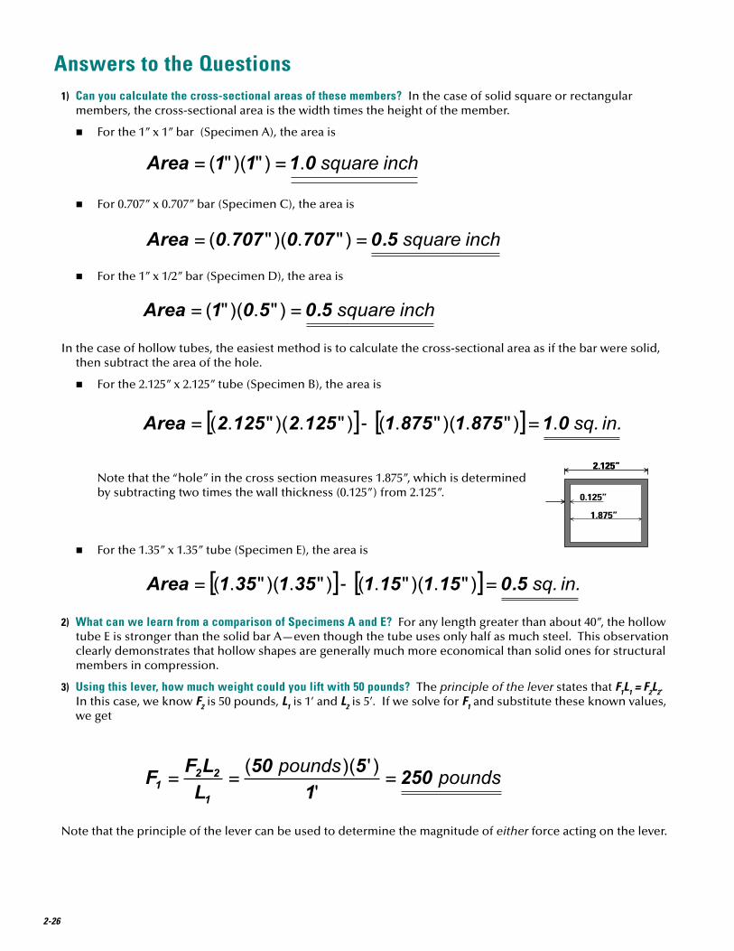
Answers to the Questions1) Can you calculate the cross-sectional areas of these members? In the case of solid square or rectangular
members, the cross-sectional area is the width times the height of the member.
n For the 1” x 1” bar (Specimen A), the area is
n For 0.707” x 0.707” bar (Specimen C), the area is
n For the 1” x 1/2” bar (Specimen D), the area is
In the case of hollow tubes, the easiest method is to calculate the cross-sectional area as if the bar were solid, then subtract the area of the hole.
n For the 2.125” x 2.125” tube (Specimen B), the area is
Note that the “hole” in the cross section measures 1.875”, which is determined by subtracting two times the wall thickness (0.125”) from 2.125”.
n For the 1.35” x 1.35” tube (Specimen E), the area is
2) What can we learn from a comparison of Specimens A and E? For any length greater than about 40”, the hollow tube E is stronger than the solid bar A—even though the tube uses only half as much steel. This observation clearly demonstrates that hollow shapes are generally much more economical than solid ones for structural members in compression.
3) Using this lever, how much weight could you lift with 50 pounds? The principle of the lever states that F1L1 = F2L2. In this case, we know F2 is 50 pounds, L1 is 1’ and L2 is 5’. If we solve for F1 and substitute these known values, we get
Note that the principle of the lever can be used to determine the magnitude of either force acting on the lever.
2.125”
0.125”
1.875”
2.125”
0.125”
1.875”
2-26

LEARN
ING
ACTIVITY #2
4) What is the weight of a 5-kilogram mass? To find the weight of a 5-kilogram mass, use the equation
5) Is cardboard ductile or brittle? Cardboard fails suddenly, with no warning and with no evidence of yielding before rupture. Therefore, it is a brittle material and would not be appropriate for use in actual structures.
6) Why was it necessary to balance the loading arm? If the loading arm were not balanced, then the weight of the arm itself would affect the force in the specimen. For example, if the long side of the loading arm were heavier than the short end (even with the clamp attached), then the weight of the loading arm would add to the internal force in the specimen. But that force would not be accounted for in our analysis of experi-mental data, because the equation T=WL2 / L1 assumes that W and T are the only forces acting on the loading arm. Thus an improperly balanced loading arm could be a significant source of experimental error.
7) Can you verify these spreadsheet calculations? The following calculations are a manual verification of the test result for the first specimen:
Given: L1 = 25 cm
L2 = 69.5 cm
Mass of bucket and sand = 942 grams = 0.942 kilogram
Convert mass to weight:
Apply the principle of the lever:
This answer matches the spreadsheet result exactly.
8) Can you use the graph to determine tensile strength?
n A cardboard member 5mm wide should have a tensile strength of about 32 newtons.
n A single 4-mm bar should have a tensile strength of about 26 newtons. The doubled 4-mm bar has twice the cross-sectional area and therefore twice the strength—about 52 newtons.
9) What are some possible sources of error in these experiments? Some possible sources of error include:
n Inaccurate fabrication of the test specimens.
n Inaccurate positioning of the specimens in the testing machine.
n Inaccurate measurement of L1 and L2.
n Inaccurate measurement of the weight of sand in the bucket.
n Improperly calibrated scale.
n Loading arm not balanced.
2-27

n Poor experimental procedure, such as adding sand too rapidly, adding sand after the specimen has failed, or not ensuring that the loading arm is horizontal at the start of the test.
n Friction at the pivot of the loading arm.
Of these sources of error, inaccuracy in the fabrication and positioning of test specimens is probably most critical. If a 4 mm tension specimen is actually only 3 mm wide, the measured tensile strength will be too small by 25% percent. If a compression specimen is not placed exactly vertically in the testing machine, all four sides of the tube will not be loaded uniformly, the member will fail prematurely, and the measured compressive strength will be much too low. None of these sources of error can be eliminated, but they can be minimized by fabricating test specimens as precisely as possible and by careful attention to proper experimental procedures.
10) Can you use the graph to determine compressive strength?
n The compressive strength of a 6mm x 10mm tube with a length of 12cm is approximately 43 newtons.
n There is no strength vs. length graph for an 8mm x 10mm tube. Nonetheless, because this member size falls between the 6mm x 10mm tube and the 10mm x 10mm tube, we can reasonably interpolate between the two curves. The compressive strength of an 8mm x 10mm tube with a length of 6cm could be estimated at approximately 49 newtons.
Some Ideas for Enhancing this Learning ActivityOnce students have completed the basic strength tests described above, have them develop and perform
experiments to answer questions like these:
n Are different cross-section shapes—triangles, I-shapes, and circular tubes, for example—more or less efficient than square tubes in carrying compression?
n Do two 4 mm bars really have the same strength as one 8 mm bar?
n Can the tensile strength of a cardboard member be improved by coating it with glue?
n What is the tensile strength of a piece of licorice? The compressive strength of a pretzel stick?
Better yet, have the students formulate their own questions, then design experiments to find the answers.
After students have completed a series of tensile strength and compressive strength experiments, ask them to assess the design of the testing machine. Working in teams, the students should study and discuss the operation of the device, then recommend at least three improvements to its configuration that will improve the accuracy of the experimental results or improve the user-friendliness of the machine. This exercise will help to reinforce what the students have already learned about tensile strength, compressive strength, levers, and experimental error. It will also get them thinking about design—the subject of two future learning activities.
2-28