Embed Size (px)
Citation preview
Dudić, P., S. et. al.: Leakage Quantification of Compressed Air on Pipes Using Termovision
THERMAL SCIENCE, Year 2012, Vol. 16, Suppl. 2, pp. S621-S631 S621
LEAKAGE QUANTIFICATION OF COMPRESSED AIR ON PIPES USING THERMOVISION
by
Slobodan P. DUDIĆa, Ivana M. IGNJATOVIĆa,*, Dragan D. ŠEŠLIJAa, Vladislav A. BLAGOJEVIĆb, and Miodrag M. STOJILJKOVIĆb a
Faculty of Technical Sciences, University of Novi Sad, Novi Sad, Serbia
b
Faculty of Mechanical Engineering, University of Niš, Niš, Serbia
Original scientific paper
DOI:
Nondestructive testing methods are increasingly in use. With these methods it is possible to obtain the desired information about the system, without altering or damaging it in any way. This paper examines the possibilities of applying these methods in the quantification of losses incurred by leaking of compressed air from the system in the terms of increasing energy efficiency of the system. The emphasis is on the application of ultrasound detector and IR (infrared) thermographic camera. The potentials and limitations of these technologies are analyzed for leakage quantification on a steel pipe in compressed air systems, as well as the reliability and accuracy of the results thus obtained.
Key words: energy efficiency, ultrasound, IR thermography, leak quantification, compressed air
Introduction
Numbers of industries use compressed air. Compressed air is very expensive energy resource. From the total costs of compressed air production 75% are spent on energy. In the EU, compressed air production contributes 10% of the total electric energy consumption in industry [1], and in some industrial branches, such as the glass industry, even 30%. Compressed air losses are present in nearly all applications and constitute 25 to 30% of the total compressed air requirements. However, there are particular systems in which this percent amounts from 30% up to even 60% [2]. On the other hand, when the manufacturing costs are calculated, it is necessary to include the costs for compressed air consumption. In that calculation, costs for compressed air consumption should be added to the machining cost, and then to the total cost bucket [3].
Leaks are the most visible and most significant contributors to compressed air losses. Leakage rate varies between 20% and 40% of the total air usage [4].
In general, most losses in the compressed air systems pressure can be classified into three main groups: losses arising from leakage of air from the system, artificial demand, and inadequate use.
* Corresponding author; [email protected]

Dudić, P., S. et. al.: Leakage Quantification of Compressed Air on Pipes Using Termovision
S622 THERMAL SCIENCE, Year 2012, Vol. 16, Suppl. 2, pp. S621-S631
Leakage is one of the largest sources of energy losses in pneumatic systems, and is the simplest and cheapest to manage for the purpose of minimizing and improving energy efficiency of compressed air. In order to reduce leakage and improve energy efficiency of the system, it is necessary to detect leaks and eliminate the causes of leaks. Active leak detection and adequate repair can reduce leaks to less than 10% of the total compressed air production.
Before implementing any improvements in a compressed air system, one should carry out measurements of losses occurring in the system due to leakage of compressed air. Quantification of losses enables a realistic insight into the amount and costs of losses, and also allows comparison of the situation before and after corrective actions and repair of the system.
Detection and quantification of compressed air leaks
Detection, quantification and repair of leaks contributes to: reduction of operating time of equipment, which prolongs its operating life; avoidance of unnecessary compressor capacity; avoidance of pressure fluctuations which deteriorate tool operation quality and diminish efficiency of equipment, potentially leading to production breakdowns; avoidance of extra maintenance time, i. e. reduction of maintenance costs, reduction of tied assets, i.e. spare parts, better utilization of maintenance personnel, reduction of noise level in workplace.
The problem of compressed air and fluid leaks has been in the focus of scientific literature for years. Numerous authors have dealt with the leakage of technical gases (propylene, ethylene, etc.), natural gas, oil, water, and other fluids [5]. Due to similar physical and exploitation properties of gases, the problem of compressed air leak detection can be dealt with equivalent to other technical gases. According to [6-8], all methods for leak detection for gases and liquids can be classified as hardware, biological or software methods.
Hardware methods are based on implementation of various devices for the detection of leaks and their locations. Based on the operating principle, these devices can be classified into four groups: visual devices (thermographic cameras, temperature sensors, GPR ground penetrating radar, etc.), acoustic devices (ultrasound detectors, acoustic sensors), gas detection devices, and pressure and flow gauges.
Biological methods for leak detection are empirical methods based on the sensory perception (hearing, smell, sight, etc.) either of the personnel or the animals that are specially trained to detect and locate leaks.
Software methods are based on using various software packages for the detection of leaks. The detection is performed by software analysis of flow, pressure, temperature, or some other system parameter, and their comparison with the set of predefined values.
Comparison and analysis of these methods and their potential application for leak detection is given in [9]. Several methods are most popular in the practical detection of compressed air leaks: detection of leaks based on sensory perception, detection of leaks by bubble test [10], ultrasound leak detection, and infrared leak detection.
In many cases, leaks can be detected quite easily. Heavy leaks are easy to hear, but the small ones are not. In some cases, a single method is sufficient to detect leaks, while in other cases a combination of methods have to be used in order to detect their location. Once the magnitude of losses is established, the total value of compressed air losses could be calculated based on the price of compressed air production per 1 m3. There are various

Dudić, P., S. et. al.: Leakage Quantification of Compressed Air on Pipes Using Termovision
THERMAL SCIENCE, Year 2012, Vol. 16, Suppl. 2, pp. S621-S631 S623
methods of compressed air leak quantification [11]. They are based, mostly, on the measurement of compressor operation time, although flow gauges, ultrasound detectors, and IR thermography are also gaining popularity [12]. Some compressed air systems feature permanent flow gauges. Flow gauges allow the monitoring of the production of compressed air, its consumption in particular components, as well as the leaks in the system. Leaks can be quantified using the following methods: a flow gauge is positioned before the pneumatic device, and the flow is measured when
the device is inactive, one flow gauge is positioned at the inlet of the tested pipeline, while another is positioned
at the outlet, so that the difference between the inlet and outlet flows represents a leak. A good ultrasound detector is vital for detection of leaks. However, it cannot provide an
exact account of compressed air leakage, i. e. money savings. On the other hand, combination of the ultrasound detector and thermographic camera can approximate the losses [11].
Nondestructive methods for leakage detection and quantification background
Ultrasound technology
Ultrasound is the sound with the frequency above the upper limit of human hearing. The audible frequency range in humans goes from 10 Hz to approximately 20 kHz. Ultrasound technology utilizes sound waves that are beyond human perception, and ranges between 20 kHz and 100 kHz.
Ultrasound technology has wide application. Ultrasound testing methods belong to the group of nondestructive testing methods (NDT). Currently, the ultrasound testing method is most popular in medicine. Non-invasive ultrasound diagnostics is mostly used for examination of internal organs [13]. Exposure of cells to ultrasound does not have harmful effects, although the ultrasound waves penetrate relatively deeply into the human body.
Besides medicine, ultrasound has also been widely used in industrial applications. It has been increasingly used in the processing, chemical, petrochemical, food, metal industry, as well as in civil engineering and architecture. It is most often used for measurement of physical quantities, such as fluid flow, fluid level, material thickness, length, surface area, volume, speed, etc. In addition, it is frequently used for ultrasound cleaning, welding, process automation (ultrasound sensors) [14], analysis of material structure [15], detection of defective machine components and subassemblies, inspection of electrical installations and equipment, detection of foreign bodies in food [16], detection of fluid leaks [17], etc.
Wide spectrum of sounds is generated by cavitation or turbulence of air molecules under the pressure, which flow out into the atmosphere through orifices, cracks, and seams. According to [18], ultrasound leak detection can be classified as active, passive, and vibroacoustic.
Active ultrasound leak detection uses one or more transmitters or receivers in non-contact or contact applications. With this method, the sound generated by the transmitter penetrates the tested structure, and after reflection off the obstacle returns to the same, or some other transmitter.
Passive ultrasound leak detection is used with compressed air leaks in reservoirs under pressure or vacuum reservoirs. In this case, the ultrasound signal is not generated by the transmitter, but is caused by the reservoir leak. Turbulence of air molecules under the pressure, which flow out into the atmosphere through orifices, cracks, and seams, produces
Dudić, P., S. et. al.: Leakage Quantification of Compressed Air on Pipes Using Termovision
S624 THERMAL SCIENCE, Year 2012, Vol. 16, Suppl. 2, pp. S621-S631
sound (also familiar as the white noise) which contains a wide spectrum of sounds, ranging from audible to inaudible frequencies. As humans are unable to sense the energy of this frequency, ultrasound equipment must be used to process the sound emission into audible sound (ultrasound converter). Ultrasound sensor (detector) is used to receive sound pressure waves of ultrasound frequency. Due to filtering, ultrasound detectors are not affected by audible background noise.
Passive ultrasound detection cannot be used reliably for quantification of compressed air leaks, but only for detection, as reported by [19]. The application of passive ultrasound on leak detection on a steel pipe in compressed air systems shall be the focus of this paper.
Infrared thermography
Infrared technology uses IR thermovision cameras to display and measure thermal energy radiated by an object. Those cameras allow a very accurate non-contact temperature measurement. In almost all compressed air systems, the occurrence of malfunction or air leak is accompanied by temperature change.
The thermal, or infrared energy, represents light emission, which is invisible to the human eye, due to high wavelength. It is the part of electromagnetic radiation, which is popularly known as heat or heat radiation. As opposed to the visible light, in the infrared spectrum every object with temperature above absolute zero emits heat. Even very cold objects, such as ice cubes, emit heat in the infrared spectrum. Object temperature and the quantity of its infrared emission are in direct proportion.
According to the method of measurement, thermography can be passive and active. Passive thermography observes objects in a stationary state. The differences between infrared emissions from the object surface are either caused by the difference in temperature or surface properties. Active thermography is based on observing the dynamic behavior of an object that is exposed to thermal excitation. Thermal excitation can be achieved in various ways. Thus, there are the impulse, periodic, lock-in, vibration, and other types of excitations. All these approaches have a common goal to transmit a packet of energy towards an object under examination, and observe its response to thermal excitation – the development in time of surface temperature distribution. Subsequent analysis can reveal the material structure beneath the surface, possible inclusions, cracks, or processes that occur beneath the surface [20]. The principles of infrared thermography are well presented in [21].
Infrared thermography constantly finds new modes of employment. It is easily used in all processes, which release thermal energy with measurable difference in temperatures. Infrared thermography is also used in civil engineering and architecture [22, 23], electric power industry [24], automotive industry [25], medicine [26], manufacturing industry [27], environment protection, and protection of historic heritage [21, 28, 29], while it is also increasingly used for fluid leak detection [30, 31]. Infrared thermography is also used in agriculture [21] and different industrial processes [32].
Thermography has been successfully applied in pneumatic systems examination. IR camera can record temperature changes in the installation and determine the locations of failures or leaks. With the scheduled actions, such as eliminating failures and locations where leak occurs, it is possible to accomplish significant savings in the consumption of compressed air, or raise the energy efficiency of the entire pneumatic system [33].
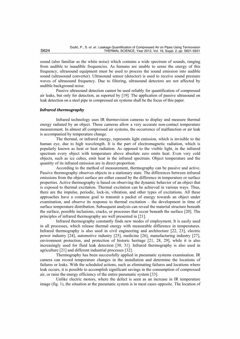
Unlike electric motors, where the defect is seen as an increase in IR temperature image (fig. 1), the situation at the pneumatic system is in most cases opposite. The location of
Dudić, P., S. et. al.: Leakage Quantification of Compressed Air on Pipes Using Termovision
THERMAL SCIENCE, Year 2012, Vol. 16, Suppl. 2, pp. S621-S631 S625
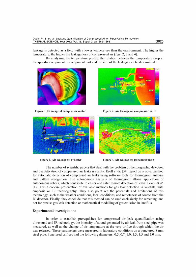
leakage is detected as a field with a lower temperature than the environment. The higher the temperature, the higher the leakage/loss of compressed air (figs. 2, 3 and 4).
By analyzing the temperature profile, the relation between the temperature drop at the specific component or component part and the size of the leakage can be determined.
Figure 1. IR image of compressor motor Figure 2. Air leakage on compressor valve
Figure 3. Air leakage on cylinder Figure 4. Air leakage on pneumatic hose
The number of scientific papers that deal with the problem of thermographic detection and quantification of compressed air leaks is scanty. Kroll et al. [34] report on a novel method for automatic detection of compressed air leaks using software tools for thermogram analysis and pattern recognition. The autonomous analysis of thermogram allows application of autonomous robots, which contribute to easier and safer remote detection of leaks. Lewis et al. [19] give a concise presentation of available methods for gas leak detection in landfills, with emphasis on IR thermography. They also point out the potentials and limitations of this technology, such as the weather conditions, local conditions, and remoteness of source from the IC detector. Finally, they conclude that this method can be used exclusively for screening, and not for precise gas leak detection or mathematical modelling of gas emission in landfills.
Experimental investigations
In order to establish prerequisites for compressed air leak quantification using ultrasound and IR technology, the intensity of sound generated by air leak from steel pipe was measured, as well as the change of air temperature at the very orifice through which the air was released. These parameters were measured in laboratory conditions on a punctured 8 mm steel pipe. Punctured orifices had the following diameters: 0.5, 0.7, 1.0, 1.3, 1.5 and 2.0 mm.

Dudić, P., S. et. al.: Leakage Quantification of Compressed Air on Pipes Using Termovision
S626 THERMAL SCIENCE, Year 2012, Vol. 16, Suppl. 2, pp. S621-S631
In order to establish the real quantity of air that escapes through the orifices, parallel to the noise level, and temperature change, compressed air flow was measured at each of the orifices. All parameters (noise level, air temperature, and air flow) were measured at each orifice, at pressures of: 4, 5, 6, 7, and 8 bar. After the measurement, the obtained levels of noise and temperature change were compared to air flow in order to establish a correlation.
The following section presents in detail the measurement procedure, related limitations, measurement instruments, and the results of measurement.
Flow measurement
In this experiment, the flow was measured by FESTO Air Box portable laboratory [35]. AirBox allows measurement of pressure, temperature, and flow. Flow can be measured statically or dynamically. Static flow measurement is used for quantification of leak losses, while the dynamic flow measurement measures compressed air consumption. Measured parameters are presentable as diagrams, or numerical values in an Excel table.
For air flow measurement in this experiment AirBox was used in the static mode, at various pressures which were kept constant during measurement. The results obtained by AirBox indicate that compressed air flow at the point of leakage gets higher with the increase of orifice diameter and system pressure. For the purpose of experiment, flow was kept within the low range (10-200 l/min).
The results obtained by measurement of flow at air exit locations on the steel pipe are given in fig. 5. Analysis of results reveals either that the flow of compressed air increases with the increase of orifice diameter, or with the increase of system pressure, which is in agreement with the expected flow increase. Similar to the flexible hose [33], the results obtained with the steel pipe indicate an increase on the flow of compressed air with the increasing of pressure and the size of the orifice. The orifices on the steel pipes are in the perfect shape and without sharp edges so the amount of compressed air that leaks through them is much higher.
Figure 5. Measured flow (l/min) on orifices on a steel pipe as function of orifice diameter and pressure
Measurement of noise level
Intensity of sound exiting the steel pipe was measured by an ultrasound detector, Ultraprobe 100 [35, 36], which accurately detects leaks and mechanical damage.

Dudić, P., S. et. al.: Leakage Quantification of Compressed Air on Pipes Using Termovision
THERMAL SCIENCE, Year 2012, Vol. 16, Suppl. 2, pp. S621-S631 S627
Noise level was measured at the loudest point of leak. Due to variable orifices shapes, rather than being perpendicular to an orifice, the loudest point is most frequently at an angle of 30° [11]. When the pressure increases, air flow increases, too, as well as the sound measured by the ultrasonic detector [33]. The punctured orifices on the steel pipe are in perfect geometry shape, without the possibilities for deformation, bending and changing shape, and their walls are smooth. Unlike the measurement of leakage on flexible pneumatic hoses, where a clear dependence between orifice dimensions and sound intensity can be established, on such orifices, we obtained the intensity noise of 75 dB, for all sizes of orifices and at all pressure levels. Therefore, it can be concluded that with the available ultrasonic detector it is not possible to determine the difference between different orifice sizes at any pressure, but just the leak location. Therefore, in order to quantify the leakage it is necessary to apply some other method such as thermovision.
Temperature measurement
The measurement of temperature difference at the location of compressed air leak was performed by IR-thermographic imager, Fluke Ti20 [38]. Ti20 is a modern noncontact infrared thermographic imager which uses IR technology for surface temperature measurement, with spectral range 7.5 μm to14 μm, thermal sensitivity 200 mK, accuracy ±2 °C or 2% (whichever is greater) and repeatability ±1% or ±1 °C (±2 °F) whichever is greater. The field of view is rectangular and covers 20° horizontally and 15° vertically [38]. It allows fast temperature readings on an LCD display without a physical contact with the object of interest. The data can be presented in several forms: thermal image, thermal profile, temperature table, and histogram. Due to the inability to directly measure the temperature of compressed air, the focus was placed on the measurement of temperature difference (ΔT) emitted by an object, in this case, the flexible hose (Tmaterial), and the temperature at the very orifice through which the compressed air is released (Torifice). Measurements were performed at orifices of various diameters, at various pressures, and constant room temperature. Based on the mean value of temperatures measured in particular zones (fig. 6), the temperature difference was calculated using eq. (2):
ΔT = Tmaterial – Torrifice (1)
Tmaterial = (T1 + T2 + T3) / 3 (2)
where: T1 – temperature of the steel pipe before the orifice [ºC], T2 – temperature of the steel pipe after the orifice [ºC], T3 – temperature of the steel pipe below the orifice [ºC].
Figure 6. Measurement location - (a) punctured steel pipe, (b) thermal image of punctured steel pipe

Dudić, P., S. et. al.: Leakage Quantification of Compressed Air on Pipes Using Termovision
S628 THERMAL SCIENCE, Year 2012, Vol. 16, Suppl. 2, pp. S621-S631
The analysis of temperature profile of the 0.7 mm orifice at 4 bar is presented in fig. 7. There is a sudden change of temperature at the orifice location. Analysis of all images leads to the conclusion that the increase of pressure in the system causes the drop in the temperature of compressed air exiting through the orifice, which, in turn, increases ΔT.
Figure 7. Analysis of temperature profile for the 0.7 mm orifice at 4 bar pressure
The results obtained by measurement of temperature differences at orifice locations on the steel pipe are shown in fig 8.
Analysis of measurement results shows that the temperature change at orifice locations is the function of the orifice size. As the size of orifice increases, regardless of pressure, there is a visible drop in temperature at air exit points.
The temperature change of compressed air on the steel pipe with diameter 8 mm increases with increasing pressure and the size of orifice. If we compare that with the flexible hose [33], these changes are more significant, indicating the greater emissivity of a steel pipe.
Figure 8. Temperature change (ΔT) at orifice locations as the function of pressure and orifice diameter

Dudić, P., S. et. al.: Leakage Quantification of Compressed Air on Pipes Using Termovision
THERMAL SCIENCE, Year 2012, Vol. 16, Suppl. 2, pp. S621-S631 S629
Discussion
In this investigation, we started from the known values of leak diameters and appropriate leak flow. But, in reality, maintenance personnel face the problem of unknown leak area and, adequately, unknown leak flow that they should, in some way, quantify. Based on these experiments, leak flow at the steel pipes can be found as the function of measured temperature change. Fig. 8 shows the diagram where, for the measured ΔT, the orifice of the leak can be found. It can be noticed that this dependence is relatively low for small leak diameters, especially in the area of up to 1.0 mm. When leak diameters are from 1.0 to 1.5 mm, the correlation is stronger. IR technology can clearly identify this change of leak flow due to the increase in leak diameter, which can be seen in fig. 9. Using the diagram from fig. 9, it is possible to detect leak flow directly from the measured temperature change (ΔT).
Figure 9. Leak flow as the function of detected temperature change ΔT (°C)
From the presented results, it can be concluded that ultrasound should be used for leakage detection for all the dimensions of orifices, yet only thermovision can be used for the quantification purposes. IR camera should be used for leakage quantification for the steel pipes and it will give a reliable estimation of leakage.
Conclusion
The presented methods for detection of compressed air leakage are of great significance for modern industrial subjects. The situations where leaks are so small that it is almost impossible to determine their exact position are very often. This paper shows the possibility for quantifying losses due to leakage using IR thermography, while some results concerning leakage quantifications have already been published for the ultrasound methods [33]. Although we used relatively imprecise measurement equipment in our experiments, we obtained a clear view of areas in which each of those methods is appropriate for quantification of leakages on steel pipes. Besides, availability of ultrasound and infrared equipment in bigger factories is increasing, so the efficiency of leakage quantification can be significantly improved with the procedures defined in this paper.

Dudić, P., S. et. al.: Leakage Quantification of Compressed Air on Pipes Using Termovision
S630 THERMAL SCIENCE, Year 2012, Vol. 16, Suppl. 2, pp. S621-S631
Based on the conducted research it can be concluded that, in case of leakage of compressed air on the steel pipes, both of the mentioned methods can be used for the leak detection. However, for the leakage quantification, the application of ultrasonic method was not possible, because the measured noise levels for all examined orifice diameters and pressure levels were the same (75 dB). It was not possible to determine the difference in the volume of the compressed air which flowed out. IR thermal imager obtained much more reliable results.
The thermal contrast (the change in temperature ΔT) between the compressed air that flowed out from the steel pipe and the steel pipe increases with increasing pressure and the orifice diameter. Applying infrared thermography for the leakage quantification purposes requires a thermal contrast at leak locations. Those contrasts are relatively low for small leaks, so infrared technology is not that precise for orifices smaller than 1.0 mm. However, the reliability and accuracy of the results are hampered by sources with weak radiation, and conditions of extreme lighting.
The approach for leakage quantification developed in this paper can also be applied for leakage of other fluids in steel pipes, e. g. LPG in pipelines and technical gases (oxygen, nitrogen, etc.) in some factories. For that purposes, in order to get valid results, it is necessary to make measurements with appropriate measuring equipment, based on the procedures defined in this paper.
References
[1] Radgen, P., Blaustein, E, Compressed Air Systems in the European Union - Energy, Emissions, Saving Potentials and Policy Actions, LOG-X Verlag GmbH, Stuttgart, Germany, 2001
[2] US Department of Energy, Office of Energy Efficiency and Renewable Energy, Assessment of the Market for Compressed Air Efficiency Services, Xenergy Inc, Burlington, Ont., Canada, 2001
[3] Koonce, D., et al., A Hierarchical Cost Estimation Tool, Computers in Industry, 50 (2003), 3, pp. 293–302
[4] Šešlija, D., et al., Potential Energy Savings in Compressed Air Systems in Serbia, African Journal of Business Management, 5 (2011), 14, pp. 5637-5645
[5] Asatryan, R.S., et al., A Spectroradiometer ror Remote Ecological Testing of Gas Main Pipelines, Russian Journal of Nondestructive Testing, 46 (2010), 8, pp. 598-602
[6] Bose, J. R., Olson, M. K., TAPS’s Leak Detection Seeks Greater Precision, Oil and Gas Journal, 91 (1993), 14, pp. 43-47
[7] Carlson, B.N, Selection and Use of Pipeline Leak Detection Methods for Liability Management into the 21st Century. Pipeline Infrastructure II, Proceedings, International Conference of the American Society of Chemical Engineers ASCE, Dallas, TX, USA, 1993, pp. 369-383
[8] Turner, N.C, Hardware and Software Techniques for Pipeline Integrity and Leak Detection Monitoring. Proceedings of Offshore Europe, Aberdeen, Scotland, (1991), pp. 139-149
[9] Zhang, J., Designing a Cost Effective and Reliable Pipeline Leak Detection System, Proceedings, Pipeline Reliability Conference, Houston, TX, USA, 1996
[10] Rozinov, A.Y., Physical Evaluation Of The Efficiency Of Applying Liquid Indicators During Leakproofness Inspection, Russian Journal of Nondestructive Testing, 42 (2006), 8, pp. 551-557
[11] SDT Ultrasound Solution, Compressed Air – Leak Surveyor Handbook, 3rd ed, SDT North America Ltd, Cobourg, Ont., Canada 2009
[12] Rozlosnik, A.E, Infrared Thermography and Ultrasound Both Test Analyzing Valves, Proceedings, SPIE, 20 Thermosense Conference, Orlando, FL, USA, 1998, 3361, pp. 137-152
[13] Jong, N.D., Frinking, P.J., Bouakaz, A., Ten Cate, F.J, Detection Procedures of Ultrasound Contrast Agents, Ultrasonics, 38 (2000), 1-8, pp. 87-92
[14] Püttmer, A, New Applications for Ultrasonic Sensors in Process Industries, Ultrasonics, 44, (2006), 1, pp. e1379-1383
[15] Zhang, J., et al., Defect Detection Using Ultrasonic Arrays: The Multi-Mode Total Focusing Method,

Dudić, P., S. et. al.: Leakage Quantification of Compressed Air on Pipes Using Termovision
THERMAL SCIENCE, Year 2012, Vol. 16, Suppl. 2, pp. S621-S631 S631
NDT & E International, 43 (2010), 4, pp. 123–133 [16] Hæggström, E., Luukkala, M, Ultrasound Detection and Identification of Foreign Bodies in Food
Products, Food Control, 12 (2001), 1, pp. 37-45 [17] Shuh-Haw, S., Hual-Te, C., Apostolos, C.R, Ultrasonic Techniques for Detecting Helium Leaks,
Sensors and Actuators B: Chemical, 71 (2001), 3, pp. 197-202 [18] Moon, C., et al., Ultrasound Techniques For Leak Detection, Proceedings, SAE 2009 noise and
vibration conference and exhibition ultrasound techniques for leak detection, St. Charles, Illinois, USA, 2009
[19] Lewis, A.W., Yuen, S.T.S., Smith, A.J.R, Detection of Gas Leakage From Landfills Using Infrared Thermography - Applicability And Limitations, Waste Management & Research, 21 (2003), 5, pp. 436-447
[20] Kulp TJ, Powers PE, Kennedy RB. Remote imaging of controlled gas releases using active and passive infrared imaging systems, Proceedings, Infrared technology and applications XXIII, Orlando, FL, USA, 1997, 3061, pp. 269-278
[21] Meola, C., Carlomagno, G.M, Recent Advances in the Use of Infrared Thermography, Measurement Science and Tecnology, 15 (2004), 9, pp. R27-R58
[22] Balaras, C.A, Argiriou, A.A, Infrared Thermography for Building Diagnostics, Energy and Buildings, 34 (2002), 2, pp. 171-183
[23] Moropoulou, A., et al., Determination of Emissivity for Building Materials Using Infrared Thermography, Journal of Thermology International, 10 (2000), 3, pp. 115-118
[24] Al-Kassir, A.R., Fernandez, J., Tinaut, F.V., Castro, F, Thermographic Study of Energetic Installations, Applied Thermal Engineering, 25 (2005), 2-3, pp. 183-190
[25] Korukçu, M.Ö., Kilic, M, The Usage of IR Thermography for the Temperature Measurements Inside an Automobile Cabin, International Communication in Heat and Mass Transfer, 36 (2009), 8, pp. 872-877
[26] Ring, E.F.J., Ammer, K, The Technique of Infrared Imaging in Medicine, Thermology International, 10 (2000), 1, pp. 7-14
[27] Meola, C, A New Approach for Estimation of Defects Detection with Infrared Thermography, Material Letters, 61 (2007), 3, pp. 747-750
[28] Carlomagno, G.M., Meola, C, Comparison between Thermographic Techniques for Frescoes NDT, NDT & E International, 35 (2002), 8, pp. 559-565
[29] Tavukcuoglu, A., Duzgunes, A., Caner-Saltik, E.N., Demirci, S, Use Of IR Thermography For The Assessment Of Surface-Water Drainage Problems In A Historical Building, Ağzıkarahan (Aksaray), Turkey, NDT & E International, 38 (2005), 5, pp. 402-410
[30] Brodetsky, E., Savic, M, Leak Monitoring System for Gas Pipelines, Proceedings, IEEE International conference acoustics, speech, and signal processing, Minneapolis, MN, USA, 1993, 3, pp. 17-20
[31] Weil, G.J, Non Contact, Remote Sensing of Buried Water Pipeline Leaks Using Infrared Thermography, Proceedings, Water resources planning and management and urban water resources, Seattle, WA, USA, 1993, pp. 404-407
[32] Jankes, G., et al., Waste Heat Potentials in the Drying Section of the Paper Machine in Umka Cardboard Mill, Thermal Science, 15 (2011), 3, pp. 735-747
[33] Dudić, S., et al., Leakage Quantification of Compressed Air Using Ultrasound and Infrared Thermography, Measurement, 45 (2012), 7, pp. 1689–1694
[34] Kroll, A., Baetz, W., Peretzki, D, On Autonomous Detection of Pressured Air and Gas Leaks Using Passive IR-Thermography for Mobile Robot Application, Proceedings, IEEE International conference on robotics and automation, Kobe, Japan, 2009, pp. 291-296
[35] FESTO, Air Box type GHDA-FQ-M-FDMJ-A – Operating Instructions, Festo AG&Co. KG, Esslingen, Germany, 2006
[36] UE Systems In, Ultraprobe 100 - user manual, Elmsford, NY, USA, 2005 [37] UE Systems Inc. Compressed air, ultrasonic leak detection guide, Elmsford, NY, USA, 2005 [38] Fluke. Ti20 Thermal Imager - Users Manual, Everet, WA, USA, 2006
Paper submitted: May 3, 2012.
Paper revised: September 20, 2012.
Paper accepted: September 25, 2012.