Embed Size (px)
Citation preview

771 E
D.
4* co -o
I 70
(114)
11113.11 A HARCOURT BRACE JOVANOVICH PUBLICATION
DECEMBER 1978 • 81 00
ELECTRONIC TECHNICIAN/DEALER
LEADING THE CONSUMER AND INDUSTRIAL SERVICE MARKETS

STATIC PROFITS? TUNE TO PTS
Tune in a clearer profit with four new profit-makers from PTS, and you'll discover four ways to higher profits with PTS.
REPLACE MENT BALUNS
A new profit-maker from PTS that will more than pay for itself after you sell the first two baluns. Selection of seven replacements (five models) will replace most baluns found in TV sets, antenna systems. MATV or CATV systems.
Dealer Net. $9.75.
PTS 8001 CO MPONENT ANALYZER
This component test instrument works in or out of circuit. Simple hook-up to any standard oscilliscope. High. medium and low range switch for matching impedance.
Dealer Net $54.95.
PTS DG-1 DIGITAL PO WER SUPPLY
External power supply for substituting voltages in televisions, stereos, radios, computers, micro-processors, appliances. CBs and many other electronic units.
Dealer Net. $114.95.
PTS DG-4 VOLTAGE CONTROL
CENTER/DIGITAL PO WER SUPPLY
Independently produces four variable DC supply voltages. Excellent for substi-tuting critical control voltages for TV electronic /varactor tuners, and many other electronic products.
Dealer Net $178.50.
TUNE ON TO MORE PROFIT THE PTS WAY. Now available from PTS stocking distributors
or at any of the PTS 42 company-owned Servicenters. Check the Servicenter Guide on the opposite page.
PTS ELECTRONICS, INC
5233 S. HWY. 37 • P.O. 272 • BLOOMINGTON, IN 47401 • 812-824-9331

• PTS SERVICENTER
GUIDE
MIDWEST PACIFIC Home Office SACRAMENTO, CA 95841
BLOOMINGTON, IN 4701 4351D Auburn Blvd P 0 41354 5233 S Hwy 37, P 0 272 916-482-6220
812-824-9331 SAN DIEGO, CA 92105 CLEVELAND, OH 44134 5111 University Ave , P 0 5794
5682 Stale Road 714-280-7070 216-845-4480 LOS ANGELES. CA 90023
KANSAS CITY, KS 66106 4184 Pacific Way 119A Merriam Lane, P 0 6149 213-266-3728
913-831-1222 PORTLAND, OR 97213 MINNEAPOLIS. MN 55408 5220 N.E. Sandy Blvd 815-W Lake St . P 0 8458 P.O 13096
612-824-2333 503-282-9636 ST. LOUIS, MO 63130 SEATTLE, WA 961 19
8456 Page Blvd , P 0 24256 988 Industry Dr (Bldg. 281 314-428-1299 P.0 88831 - Tukwila Branch
DETROIT, MI 48235 206-575-3060 13707 W 8-Mtle Rd 313-862-1783
GRAND RAPIDS, MI 49501 1134 Walker Northwest
P 0 1435 NORTHEAST 616-454-2754 CINCINNATI. OH 45218 8172 Vine SI P 0 16057
513-821-2298 MILWAUKEE, WI 53218 7211 Fond du Lac 414-464-0789
COLUMBUS, OH 43227 1742-44 State Rd P 0 207 4005A E Livingston 215-352-6609 614-237-3820 PITTSBURGH. PA 15202
INDIANAPOLIS. IN 46202257 Riverview Ave W , P 0. 4130 1406 N Pennsylvania Ave
317-631-1551 DAVENPORT, IA 52603 2024 E River Dr 319-323-3975
OMAHA, NE 68132 5008 Dodge Street 402-558-1800
CHICAGO, IL 60659 5744 N Western Ave 1167 Massachusetts Ave P 0 37
312-728-1800 617-648-7110 BALTIMORE, MD 21215
SOUTH 5505 Reisterstown Rd . P 0 2581 ATLANTA, GA 30318 301-358-1186
1240 Techwood Drive N W P 0 93887 404-873-1787
JACKSONVILLE, FL 32210 918 Bianding Blvd , P 0 7923 MOUNTAIN
904-389-9952 WASHINGTON. DC DENVER
Arvada, CO 80001 Silver Spring. MD 20910 4958 Allison St . P 0 672 8880 Brookville Rd
303-423-7080 301-565-0025 CHARLOTTE, NC 28225 SALT LAKE CITY, UT 84106 726 Seigle Ave P 0 5512 1233 Wilmington Ave
P 0 6218 704-332-8007
BIRMINGHAM, AL 35201 801-48A-1451 PHOENIX, AZ 65009 210 N 9th St , P 0 1801
205-323-2657 2916 West McDowell Rd MEMPHIS, TN 36118 602-278-1218
3614 Lamar Ave P 0 18053 901-365-1918
NORFOLK, VA 23504 3118 E Princess Anne Rd
804-625-2030 NEW ORLEANS SOUTHWEST Metairie, LA 70004 LONGVIEW, TX 75601
3920A Airline Hwy P 0 303 110 Mopac Rd. P 0 7332 504-837-7569 214-753-4334
TAMPA, FL 33690 OKLAHOMA CITY, OK 73147 2703 S Macdiii, P 0 14301 4509 NW 10th, P.0 74917
813-839-5521 405-947-2013 NASHVILLE, TN 37214 HOUSTON, TX 77207 2426 A Lebanon Rd 4326 Telephone Rd , P 0. 26616 I' 615-885-0688 713-644-6793
SPRINGFIELD. MA Westfield, MA 01085 300 Union St . P 0 238
413-562-5205 PHILADELPHIA
Upper Darby, PA 19082
412-761-7648 E. PATEFISON, NJ 07407 158 Market St . P.0 421
201-791-6380 BUFFALO, NY 14214 299 Parksfde Ave 716-837-1656 BOSTON
Arlington, MA 02174
111DUSTRY REPORT \
Moch Named Head of Warranty Watchdog Committee The Consumer Electronic Council, a group comprised of large warranty ser-vicers and three national associations—NARDA, NATESA, and NESDA—has named Frank J. Moch head of its warranty watchdog commit-tee. Moch, the executive director of
NATESA, was elected at a reorganiza-tion meeting of the council held recently in Chicago. The purpose of the special council is to acquaint manufacturers with specific implementation problems designated by the council as "contrary to the interests of the set purchasers and all elements of the home electronics in-dustry." According to a statement from the
council, 17 specific warranty problems have already been identified, "six of which are particularly onerous." Moch said each alleged violator will be pri-vately contacted in an effort to gain war-ranty problem modifications. The council has already sent large
warranty service organizations across the United States a questionnaire on the specific warranty practices of 10 televi-sion receiver manufacturers. The manu-facturers on which data is being col-lected are Admiral, GE, Panasonic, Quasar, RCA, Sony, Sylvania, Zenith, MGA, and Sharp.
JVC Unveils Capacitive Pickup Video Disc System A grooveless, capacitive pickup video disc system, capable of playing one-hour of color television programming per side, has been announced by Victor Company of Japan (JVC). According to JVC, the player is con-
nectable to any "ordinary" color televi-sion receiver. It plays a 12-inch plastic disc that may be recorded with color television programming or pulse code modulated stereo. The basic features of the JVC system
are: Picture and sound information —
including PCM stereo—are recorded as pits on the disc surface via laser beam. For playback, information and tracking signals are simultaneously picked up electronically as capacitance variations between the disc surface and an elec-trode on the tracking stylus. The tracking stylus, JVC says, is lo-
cated in a cantilever arm which is servo controlled to track the imaginary grooves and to correct for the time base
M21171
error of the rotating disc via an electro-tracking system. According to JVC spokesman en-
gineering studies indicated a system for both home and industrial use would be the most advantageous. "In other words, we wanted a system which our industrial and domestic consumers would welcome."
FCC Seeks More Data on AM Stereo /The FCC says it wants more data plus some persuasion of the "need" for AM stereo before it makes any hard and fast dicisions concerning competing sys-tems and authorization. Citing "great interest" for AM stereo
on the part of some manufacturers and broadcasters, the commission noted a similar lack of interest on the part of the general public. Going so far as to question the need
for AM stereo, the FCC requested more data on the price impact on the public plus, it said, many technical standards remain unresolved. Among the deficien-cies noted were the impact of the reduc-tion in AM bandwidth and channel spac-ing under international law, the effects on listeners who depend solely on skywaves, and receiver compatibility. The FCC's chief engineer, Raymond
Spence, asked the question who wants AM stereo except perhaps manufactur-ers and broadcasters?
IHF Speeds Work on Technical Standards The Institute of High Fidelity, an organ-ization consisting of manufacturers of stereo components, says it is taking steps to speed the development of its technical standards program. IHF President Jerry Kalov, president
of Jensen Sound Laboratories, says, because of the growing need "for more such industry standards" the IHF Board of Directors has activated standards committees for turntables, cassette rec-orders, and speakers. This, he said, is considered one of the most valuable programs for the development of com-prehensive high fidelity standards. One of the committees has already
met, according to Kalov, and has set initial goals for the development of stan-dards for turntables. A first order of busi-
Circle No. 122 on Reader Inquiry Card ETID - December 1978 I 1

RICHARD W LAY
Editor
WALTER H SCHWARTZ Managing Editor
ALFRED A MENEGUS
Publisher
DAVID J HAGELIN Associate Publisher
TOM GRENEY Publishing Director
JOHN PASZAK Graphic Design
KATHY TARNOWSKI Production Manager
LILLIE PEARSON Circulation Fulfillment
On the cover: With the colors of the approaching
holiday season on our cover, the staff of ET/D extends to one and all best wishes for
the coming year.
T11) FEATURES
ELECTRONIC TECHNICIAN/DEALER
LEADING THE CONSUMER AND
INDUSTRIAL SERVICE MARKETS
DECEMBER 1978, VOL. 100, NO. 12
Phase locked loops revisited They're popping up all over the place
Microprocessor technology ETID's continuing series on consumer applications
Zenith's systems Ill A 100 percent modular, chassisless TV
ET/D's 1978 subject reference index An alphabetized reference for the past year
12
20
28
32
DEPARTMEATS INDUSTRY REPORT
FROM THE EDITOR'S DESK
LETTERS
NEWSLINE
SERVICE SEMINAR
BULLETIN BOARD
TEST INSTRUMENT REPORT
DEALERS SHOWCASE
NEW PRODUCTS
CLASSIFIED ADS
ADVERTISING INDEX
READERS SERVICE
TEKFAX
1
_ 6
8
9
10
_38
40
42
44
_46
48
49
_ 51
1111j A HARCOURT BRACE JOVANOVICH PUBLICATION
HARCOURT BRACE JOVANOVICH PUBLICATIONS Robert L EdgeII, Chairman, Richard Moeller. President, Arland Hirman, Treasurer. Lars Fladmark, Senior Vice President, Joe Bilderhach, Vice President, James Gherna, Vice President. George Glenn. Vice President. Thomas Greney, Vice President. Ezra Pincus. Vice President, Harry Ramaley. Vice President. Lois Sanders. Vice President
ELECTRONIC TECHNICIAN DEALER IUSPS 172360Iis published monthly by Harcourt Brace Jovanovich Publications Corporate offices 757 Third Avenue. New York. New York 10017 Advertising offices 757 Third Avenue. New York, New York 10017 and 43 East Ohio Street, Chicago, Illinois 60611 Editorial offices 43 East Ohio Street. Chicago, Illinois 60611 Accounting. Advertising Production and Circulation offices 1 East First Street, Duluth, Minnesota 55802 Subscription rates one year, $9. two years, $15, three years. $19, in the United States and Canada All other countries one year, $20, two years. $35, three years, $45 Single copies $1 in the United States and Canada. all other countries $3 Application to mail at Controlled Circulation postage rates is pending at Dansville. New York 14437 Copyright c 1978 by Harcourt Brace Joyanovich. Inc All rights reserved No part of this publication may be transmitted or reproduced in any form or by any means, electronic or mechanical, including photocopy, recording or any information storage and retrieval system. without permission in writing from the publisher ELECTRONIC TECHNICIAN DEALER is a registered trademark of Harcourt Brace Jovanovich, Inc
POSTMASTER Send Form 3579 to ELECTRONIC TECHNICIAN DEALER. P 0 Box 6016, Duluth, MN 55806
2 / ET ID - December 1978

AMERICA'S LARGEST SUPPLIER of ORIGINAL Japanese Semi-Conductors
for CB, TV and Stereo Repair
We carry only genuine replacement parts
1 YPE 25-UP 10-24 TYPE 25 UP 10-24 1- TYPE 25 UP
2SA 102
2SA 234
254 473
2SA 484
254 495
2SA 497
2SA 509
254 561
2SA 562
254 564A
2SA 634
2SA 643
?SA 673
254 678
2SA 682
?SA 683
254 684
2SA 695
2SA 699A
2SA 706
254 719
2SA 720
254 733
2SA 747
254 818
?SA 841
20
45
45
1 50
30
1 00
30
30
30
20
40
30
35
35
80
30
35
40
50
85
30
30
20
4 20
70
20
27
53
53
1 75
31.
1 2(
2;
41
4C
40
40
90
30
40
52
64
1 0(
37
4 40 9(1
30
59
59
1 95
40
1 30
40
40
40
30
50
45
45
1 00
40
45
59
70
10
40
40
30
4 50
2S13
2SB 22
2SB 54
2S6 75
2SB 175
2SB 186
2513 324
256 337
2SB 405
2SB 407
25E1 434
2SB 435 2513 463
2SB 473
2SB 474
2SB 492
256 507
256 5280
256 595
25E1 596
30
20
35
20
20
30
70
30
80
80
90 90
80
70
60
80
70
1 10
1 10
35
27
4P
27
35
80
35
90
90
1 10
I 10
90
80
70
90
80
1 40
1 40
40
30
45
30
30
40
90
40
1 00
1 00
1 20
1 20
1 00
90
80
1 00
90
1 50
1 50
2SC
2SC 281
2SC 372
2SC 373
2SC 380
2SC 394
2SC 458
2SC 495
2SC 509
2SC 515A
2SC 517
2SC 535
2SC 634A
30
20
20
20
20
20
45
35
80
2 50
30
35
35
27
27
27
27
27
55
40
90
2 70
35
40
40
30
30
30
30
30
60
45
1 00
3 00
40
45
2SC 696
2SC 710
2SC 711
2SC 730
2SC 732
2SC 735
2SC 756
2SC 756A
2SC 781
2SC 784
2SC 799
2SC 828
2SC 839
2SC 867
2SC 8674
2SC 897
2SC 930
2SC 945
2SC 983
2SC 959
2S C 10006 L
2SC 1014
2SC 1018
2SC 1030C
2SC 1061
2SC 1079
2SC 1096
2SC 1098
2SC 1111
2SC 1124
2SC 11728
2SC 1173
2SC 1226
2SC 1226A
2SC 1239
2SC 1306
2SC 1307
2SC 1318
2SC 1383
2SC 1384
2SC 1419 2SC 1675
2SC 1678
2SC 1728
2SC 1730
2SC 1760
2SC 1816
2SC 1856
2SC 1908
2SC 1909 2SC 1945
2SC 1957
2SC 1970
2SC 1978
2SC 2028
2SC 2029
2SC 2076
2SC 2091
ISC 2092
2SC 2166
2SD 72
1 00 I 20
20 27
20 27
300 320
20 27
20 27
1 50 1 80
1 50 1 80
1 90 210
30 35
200 220
20 27
30 35
320 340
320 340
200 220
20 27
20 27
50 64
1 10 1 20
3S JO
50 64
60 70
1 80 210
70 80
i 40 355
45 55
50 64
210 250
80 90
20 360
55
50 SS
50 .S6
220 270
1 30 1 45
' 9,1 2 10
15 40
10 35
35 40 60 70
20 27
1 10 1.25
70 80
45 53
70 80
1 50 175
50 64
30 35
1 80 200
450 500
60 70
210 250
540 600
50 64
1 50 1 80
50 64
90 1 10
1 80 200
1 40 160
2SD 50 64
1 30
30
30
3 40
30
30
2 00
2 00
2 40
40
2 50
30
40
3 70
3 70
2 50
30
30
70
1 30
45
r 0
'80
240
90
3 90
60
70
2 80
1 Or
3.9",
61/
60
60
290
160
240
45
40
45
80
30
1 40
90
59
90
1 95
70
40
225
560
80
280
660
70
200
70
I 20
225
1 80
70
2S0 234
2SD 235
2SD 261
2SD 287
2SD 313
2SD 315
2513 325
2SD 427
2SD 525
2SD 526
2SK 19131.
2SK 23
2SK 30
2SK 31
2SK 55
3SK 22Y
3SK
AK 4,,
3S/( 41
3SK 45
3SK 40
3SK 09
90 AN 2140
AN 2
AN 241
AN 274
AN 313
AN 31 -
BA 511
BA 521
HA 1151
HA 1156
HA 1306W
HA 1322 HA 1339
HA 1339A
HA 1366
HA 1366W
HA I366W R
LA 4031P
LA 4032P
LA 4400
LA 4400Y
LA 4420
M515I3L
STK 011
STK 013
STK 015
STK 435
TA 7045M
TA 7060P
TA 7061P
TA 7062P
TA 7089P
TA 7202P
TA 7203P
TA 7204P
6C
60
35
250
60
60
60
1 80
90
60
45
70
40
60
60
I 40
90
90 1 30
1 30
.1 40
1 30
1 30
4 20
25.0 1 50
3 00
1 GO
1 80
1 90
1 50
1 60
2 00
2 50
2 50 2 50
2 50
2 50
2 50
1 80
1 80
1 90
2 00
2 00
2 00
3 80
7 60
4 20
4 50
2 00
70
90
1 10
2 00
2 50
2 50
2 00
10-24 1 9 I TYPE
70
70
40
2 70
70
70
70
2 00
I 10
70
55
80
45
70
70
1 60
1 10
I 10
1 45
1 45
1 55
1 45
1 70
4 40
2.70
1 75
3.20
2 00
2 00
210
1 75
1 80
2 20
2 70 2 70
2.70
2 70
2 70
2 70
2 00
2 00
2 10
2 20
2 20
2 20
4 00
8 00
4 40
5 00
2 20
80
1 10
1 25
2 20
2 70
2 70
2 20
80
80
45
2 90
80
80
80
2 25
1 20
80
60
90
50
80
80
1 80
I 20
1 20
1 60
1 60
3 90
I 60
4 90
3 00
1 95
3 40
2 25
2 25
2 40
1 95
2 00
2 50
3 00
3 00 3 00
2 90
2 90
2 90
2 25
2 25
2 40
2 50
2 50
2 50
4 40
8 80
4 90
5 60
2 50
90
1 20
1 40
2 50
2 90
2 90
2 50
25-UP 10-24
TA 7205P
TA 7310P
TBA 810SH
TC 5080P
IC 5081P
IC 5082P
UH1C 002
UH1C 004
UHIC 005
UPC 20C
UPC 563
UPC 575C 2
UPC 576
UPC 592HZ
UPC 1001
UPC 1008C
UPC 1020H
UPC 1025H
UPC 1154
UPC 1155
UPC 1156
UPI 14305
UP!) 861
UP!) 867
UPC) 858
PLL 010
PIA 020
PLL OJA
1 60
1 30
1 90
5 00
3 00
3 40
4 20
1 20
4 20
2 10
1 90
1 30
1 90
70
1 90
4 20
1 90
I 90
2 00
2 00
1 90
3 00
8 00
8 00
6 00
1 00
5 00
7 60
I 80
1 45
2 10
5 20
3 20
3 55
0 40
4 40
4 40
2 50
2 10
1 45
2 10
80
2 10
4 40
2 10
2 10
2 20
2 20
2 10
3 20
8 40
8 40
6 30
4 20
5 30
8 00
2 00
1 60
2 40
5 80
3 40
3 90
4 90
4 90
4 90
2 80
2 40
1 60
2 40
90
2 40
4 90
2 40
2 40
2 50
2 50
2 40
3 40
9 50
9 50
7 00
4 60
5 90
8 80
DIODES
IS 84
1S 332
IS 953
is 1007
IS 1209
IS 1211
IS 1555
IS 1588
is 1885
1S 2076
IS 2093
IS 2473
IN 34
1N 60
100 1
100 10
VO6B
WZ 071
WZ 075
WZ 090
WZ 120
WZ 192
SC 613
78L05
MPS U31
Mini mu m order $5.00 Add $1 00 postage ancilhandling Ask tor our co mplete price It when ordering Overseas
buyers. Manutacturers. Distributors or Dealer orders welco me All parts are guaran eed against factory defects
for one year. C. 0 D. orders are welco me 48-hour delivery
ORDER TOLL FREE EAST
Natio..414 800-543-1607 Ohm 800-582•1630 Mon-Fn 100010 700 Saturday 100010500 PO Bo m 40325 • Cinctnnan00,0 45240
WEST
Naloononde 800 543 1642 Caillornoa 1Ca11 Collect> 213 533 1221 Mon Fro 9 00 10 5 00 *Sal 9 00 to 3 00 P 0 Box 3375• Torrance Caillornia 90510
Telex: 21-4732 m• uli-Svea,
45
35
16
35
35
35
20
20
16
20
35
16
12
12
30
45
30
ZENERS
20
20
20
20
20
MISC
5 20
90
1 50
55
40
18
40
40
40
22
22
18
22 40
18
13
13
35
55
35
22
22
22
22
22
5 40
1 00
1 70
60
45
20
45
45
45
25
25
20
25 45
20
15
15
40
60
40
25
25
25
25
25
5 95
1 10
1 90
ET D - December 1978 3

ness will be development of a glossary of terms, the separation of such terms into groups, the development of stan-dard test conditions, and development of a set of measurement standards for the various groups.
Zenith Reports Improved Finan-cial Results Zenith Radio Corporation has reported improved third quarter financial results for the period ending Sept. 30. According to Zenith's consolidated
statements of income, net sales were up 12.2 per cent to $276.6 million during the three months period while net income showed a profit of $6.4 million —or 34 cents per share, compared with a 69 cents per share loss for the correspond-ing period a year earlier. For the nine months period, sales
were up slightly to $703.4 million while earnings showed a per share increase of 46 cents, to 70 cents per share, on 18.8 million shares outstanding.
Winter CES to Feature Audio Merchandising Next month's Winter Consumer Elec-tronics Show, Jan. 6-9 in Las Vegas, will feature expanded emphasis on retail merchandising programs of consumer electronics products...especially in the highly competitive audio field. According to Jack Wayman, Senior
Vice President of CES, about half of the 31-scheduled hours of showtime will be devoted to "consumer electronics product knowledge, retail store man-agement and sales development." Each of the four mornings of the
show—starting Saturday Jan., 6—will be devoted to two separate retail and merchandising conferences. Starting off on the 6th will be Personal Communica-tions at 8:30 a.m., followed by the Tele-phone Devices conference at 10:30. The following days' conferences will
be audio systems and auto sound; tele-vision, projection TV and video systems; and personal computers, TV games, calculators and watches. CES also reports that for the benefit of
attendees a special "retail idea center" will be on the convention floor and will feature 100 of the most outstanding re-tail merchandising techniques. This in-cludes theme promotions, retail adver-tising campaigns, direct mail, commu-nity relations, store design and product display. Also, according to sopkesmen for the
show, a CES retail resource center will offer attendees an opportunity to consult with 15 exhibitors who provide nation-wide retail store services such as financ-ing, store design and lighting, freight bill auditing service, retail management services, merchandising aids, and retail sales training. rr
ATTENTION SERVICE DEALERS
• Buy Directly • Top Line Solid State Replacements, Original Japanese Transistors and Integrated Circuits
PARTIAL LIST • MONTHLY SPECIALS Part Your Part Your Part Your Number Cost Number Cost Number Cost
AN 214 AN 247 TA 7205 2SA 495 2SA 643
1.75 2.50 1.80 .35 .35
2SI3 474 2SC 756A 2SC 799 2SC 1096 2SC 1358
.75 1.80 1,95 .55 2.90
2SC 1383 2SD 72 2SD 202 2SK 23A 121-831
.30
.70 2.50 .70 4.50
Free gift with every $25 purchase!
Send for our complete list of Japanese parts and prices
• Our Professional Replacement parts are top quality and replace over 130,000 indus-try types at a substantial savings to you over most other replacement lines.
• To order, just send us the ECG, SK, GE, or other part number and we will promptly ship you the premium PR direct replacement, plus a free PR replacement guide. Remember—these are first quality parts —no culls, no seconds! 2 year warranty on all parts.
• Orders over $25.00 shipped free, under $25 add $1 UPS. C.O.D. orders are welcome. To approximate the cost of a replacement part order, deduct 40% from dealer cost of ECG or other types. All orders shipped within 24 hours.
DEVCO Write or Call — Toll Free 800-526-4463
P.O. Box 270, Garwood, NJ 07027. (201) 688-0300
ST/D Richard W. Lay, Editor (Chicago)
Walter H. Schwartz, Managing Editor (Duluth)
Alfred A. Menegus, Publisher (New York)
David Hagelin, Assoc. Publisher (Chicago)
Tom Greney, Group Vice President (Chicago)
John Paszak, Graphic Design
Kathy Tarnowski, Production Manager
Karen Cranmer, Prod. Supervisor
Lillie Pearson, Circulation Supervisor
Gene Bailey, Reader Service
Ed Schultheis, Promotion Director
Dawn Anderson, Classified Ad Mgr.
Please submit editorial manuscripts to: Editor, ET/D, 43 East Ohio St. Chicago, III., 60611
ADVERTISING SALES
Please send advertising material to: ET/D, Production Mgr. 1 East First Street Duluth, Minn. 55802 (218) 727-8511
East Region Alfred A. Menegus 757 Third Avenue New York, N.Y. 10017 (212) 888-4382
Midwest Region David J. Hagelin and Thomas P. Kavooras, Jr. 43 East Ohio Street Chicago, III. 60611 (312) 467-0670
Southern & Western Region Chuck Cummings 613 N. O'Connor Irving, TX 75061 (214) 253-8678
11 13.11
HARCOURT BRACE JOVANOVICH PUBLICATIONS
Robert L. Edgell, Chairman
Richard Moeller, President Lars Fladmark, Senior Vice President
Arland Hirman, Treasurer
Joe Bilderbach, Vice President James T. Gherna, Vice President
George A. Glenn, Vice President
Thomas Greney, Vice President Ezra Pincus, Vice President Harry D. Ramaley, Vice President
Lois Sanders, Vice President
Circle No. 106 on Reader Inquiry Card 4 ET/D - December 1978

Graham Holmes Sound Engineer, Aerosmith Winter Tour '77,
Tasco Sound. Newburgh, NY; London, England; Los Angeles, C
fro "I cant afford foulf-ups on the roa After al1,11,000 people bought 'tickets to see Aerosmithe
Sail demand GE compo , Your reputation is our reputation
Tube Products Department • Owensboro, Kentucky 42301

room THE
EDITOR'S DESK
I suppose I could start this editorial with the traditional saying that as the end of another year approaches, it seems a good time for all of us to pause and reflect on our accomplishments during the past 12 months.
I could, but won't ... simply because none of us in this industry has very much time for reflecting.
What we will recall about 1978 though, as the years go by, is that if it is at all possible to pin any kind of a label on it, insofar as the consumer and home entertainment electronics service industry is concerned, it should rightfully be known as the year of the digital IC. Already completed as we entered 1978 was the transformation of
the major analog signal processing circuitry—sound, video, chroma, from transistors to integrated circuits. In most cases
on-board voltage regulators were already in place to help confuse the uninitiated.
The new year brought the wholesale influx of electronic digital tuning into America's living rooms, including late this year, digitally synthesized tuning from RCA and Zenith's on-circuit-board electronic tuning system.
Just a very few years ago (1973) we witnessed the last of the electron tube television sets roll off the assembly line to be followed by transistorized versions. We now see the advance of the digital IC into the frequency (horizontal and vertical) control sections of the home TV receiver in the form of more counters and dividers. Even a new commercially viable system for processing video and
color information in the receiver (Magnavox's comb filter) is with us. And, already the micro-processor is upon us. Programmable microwave ovens; programmable stereo components;
programmable home blenders, etc., etc. Get the picture?
Over the last year ET/D has had the priviledge of trying to keep
track of the accelerating pace of change in our industry—and passing what we have learned on to you. Really—what it all boils down to is an educational crisis for most
of us associated with consumer electronics. Where can the modern serviceshop of today and the proficient
technician, get the kind and quality education he needs to continually upgrade his electronic skills.
This is an area that is now clearly emerging as one of the very most important facing the independent electronic serviceshop. We at ET/D will be looking for the answers to these questions in the new year.
Merry Christmas and Happy New Year.
Sincerely,
6 / ET/D - December 1978

Get your fastening act together with Mallory-Ridtco.
(Parts shown actual size.)
Clamps, clips, wire sacdles, spacers,
cable hangers, circuit poard supports,
guides and dozens of ct-er accessories.
Your Mallory distributor has them. Pack-aged the way you wart them. See him
soon. Or contact Ma'lory Distrioutor
Products Company, a division of P. R.
Mallory & Co. In., Box 1284, Indianapolis,
Indiana 46206. i'317) 856-3731.
WIMPY RICPCO fallenIng °Biqa; 4 , 4 L41(1 LIAM,hAF. IN NO '6 DM
Circle No. 117 on Reader Inquiry Card
MALLORY Capacitors • Contrcls • Fastening Cevices • Resistors • Security Products • Semiconductors • Solde -lc ss Ter mina's • E-:onalert Signals • Switches

LETTERS HELP WANTED
I'd appreciate any help you or your
readers can provide in getting service info for a Sears Model 562.40291400 Color TV. It was not listed in Sam's cur-
rent index, and the local Sears store could not get it for me. Thanks,
Marc W. Scharf
Audio Video Service 5109 Algonquin Trail
Kukomo, IN 46901
I am in need of a schematic for a
MIKADO Model 1224 AM-FM-Stereo and have had no success in obtaining
one. I wrote to an address in San Fran-cisco buy my letter was returned marked "out of business." Very truly, Frank Neal
3647 Viaorilla Lompoc, CA 93436
I have been a subscriber to your maga-zine for years. I need a little help now!
My own AM-FM-SW radio has a broken FM-AM-MB-SW switch. I cannot get a
part for it. The radio is a YORK Model-B/E-124 Can anyone help me? Thank you, Leslie Vargas
8921 Roosevelt Blvd. Philadelphia, PA 19152
I need the address of Lavoie Laborato-ries that used to be in Morganville, New
Jersey and also the operating and ser-
vice manual on a Lavoie Oscolloscope Model LA-545 which is not exactly like a Tektronix 545. Thanks,
Rejean Mathieu 660 13th Ave.
P.O. Box 1601
Sennetere, Quebec, Canada JOY-2M0
I need a schematic for an AMIFMI8
track stereo system. I cannot get any
information through the store where it was purchased. It is an Electra made by Electra Radio Corp., Model No. 8TR-400 Series A. Any help would be ap-preciated. Stanley E. Johnson 4201 Winegar Rd. Bancroft, MI 48414
In your next edition of ETID magazine
would you please print the following message to your readers. 'need service literature and a schematic for a B&K Model 1050 video and audio generator
and for a New London Instruments Co. Model 901A Transconductance Ana-
lyzer. Both need repair. Any help would be appreciated.
Ris Electronics Co. 1542 Averitt Road
Greenwood, IN 46142
I have a color TV made by Division of Sparten's Industries Inc., N.Y., N.Y.
10001, distributed by KORVETT'S, Model #1869. The number of the chas-sis 1013AH. I have tried several ways to
obtain information. Your column has been helpful before. I hope someone
can put me on the track of a schematic. Fred Berberich 131 Washington Ave.
Tappan, NY 10983
NE W TUNERS NOT universal or customized NOT seconds,
culls, dogs, or oddballs Only $24.95 for ANY
new tuner. Over 5,000 in stock including Phulco TT192
CALL TOLL FREE 1-800-433-7124
TEXAS TUNER SUPPLY 4210 NE 28th St, Ft Worth, TX 76117
Circle No. 125 on Reader Inquiry Card
Original Japanese Replacement Parts for TV, Stereo and CB 25.UP 10.24 14 25.UP 1044 14 25.UP 1424 14 25.UP 1044 1.9 ; 25.UP 1424 14 25.UP 10-24 14
r 254102 .29 .34 .39 2SC460 .46 .50 .55 20C1114 3.40 3.80 3.80 25C2072 3.55 3.75 3.95 45247P 2.40 2.50 2.90 TA7089P 1.95 2.15 2.45 204473 45 .55 SO 2SC481 1.25 1.35 1.45 25C 11164 3.20 3.45 3.80 25C2076 .05 50 55 45274 1.50 1.70 1.90 747092 440 4.90 540 254484 1.85 2.05 2.35 250482 1.25 1.35 1.45 20C1124 .80 .85 .95 2SC 2091 85 1.05 1.15 55 313 4.20 4.40 4.60 T 47120P 1.45 1.65 1.85 254495 .25 .30 .35 2SC485 1.26 1.36 1.45 2SC 1127 .80 .85 .95 25C2092 1.75 1.96 2.20 55 375 1.75 1.95 2.20 TA7139P 1.55 1/5 1.95 254497 20 1.15 1.25 2SC495 45 55 AO 2SC 1162 .70 .75 .85 2SC 2098 3.00 3.20 3.45 B45114 1.70 1.90 2.15 147153P 570 590 6.10 2S4509 30 35 .40 200509 .30 AO .45 20C1166 .25 .35 40 25072 .50 .60 .65 134521 1.85 2.06 2.35 157203P 2.45 250 2.85 204567 .25 30 .35 25C517 2.90 3.10 3.25 20C11728 3.10 .3.50 3.85 25091 1.30 1.40 1.55 HA1151 1.40 1.70 1.85 147204P 1.95 2.10 245 2545644 .29 34 39 25C535 .30 .35 AO 2501173 .50 55 .70 2SD92 140 1.55 1/5 HA1156 1.60 1.75 las T A 7205P 155 1.75 125 254634 35 .40 .45 200620 .45 .50 .55 2SC1177 1020 1240 1380 2013180 155 1.75 125 1441306W 1.90 2.10 2.40 147214P 3.90 4.20 4.50 204636 AO 85 ao 2SC6324 .35 .40 .45 25C1209 .25 .35 AO 250187 .30 AO .45 H41322 2.40 2.60 290 14731OP 1.25 1.40 1.55 204643 30 .35 AO 2006344 .40 .45 .60 2SC 1226 .50 .60 .70 200218 2.95 3.20 3.45 1151339 2.45 2.65 2.95 747607P 5.80 6.00 6.20 204673 .30 .40 .45 2 506975 3.20 3.50 3.90 25C 12264 .50 .60 .70 200234 .60 .70 20 H413394 2.45 2.65 2.95 147609P 4.40 4.60 4.80 254678 .40 .50 .55 200710 .20 .27 .30 = 1237 1.70 1.90 2.15 200235 .60 .70 BO LA1222 2.10 2.30 2.50 TBA8105H 1.85 2.05 2.35 204683 AO .50 .55 250711 .20 .27 30 2SC 1239 2.10 2.65 2.85 200261 .30 35 AO LA3101 3.45 3.60 3.75 TC5080P 420 500 5.60 204684 .40 50 .55 250712 .20 .27 .30 2SC 1306 1.25 1.65 155 200287 250 2.65 2.85 L 44031P 1.75 1.55 2.20 TC513131P 2.90 3.10 3.30 204695 .40 .50 .55 250717 .35 AO .45 25C 1307 2.15 2.65 2.85 200291 2.05 2.45 2.75 144032P 1.75 125 2.20 TC5082P 3.30 345 3.80 2046994 .50 50 .65 250730 2.95 3.15 3.35 2SC1318 .30 AO .45 200313 AO .65 .70 154220 2.25 2.40 2.55 UHIC001 420 5.10 5.60 254706 .85 .95 1.05 250732 .20 .25 .30 2SC 1364 ..:,., 40 .45 200315 50 .70 AO 1444130 1.85 2.05 2.35 UH IC002 490 5.10 5.60 254720 .30 .35 .40 750133 .20 .25 .30 2SC 1383 .30 .40 .45 250325 .60 .65 .75 103141 1.70 1,80 1.90 UH IC003 420 5.10 5.60 254733 .25 27 .30 250734 .20 .25 .30 2SC 1384 .30 .40 .45 200330 .69 .79 .89 M5115P 4.85 4.90 4.95 UH IC004 4.90 5.10 5.60 254747 4.15 4.35 4.85 250735 .20 .25 .30 2SC 1424 2.75 2.85 2.95 200356 .70 .75 .80 M515131 1.95 2.15 2.45 UH IC005 490 5.10 5.60 20022 .45 50 55 250756 1.45 1.75 1.95 2SC 1448A 1.00 1.10 1.20 200358 .70 .80 20 MN3001 13.20 14.85 16.50 UH IC006 420 5.10 550 25254 .30 .35 AO 2507564 2.00 2.10 2.20 20C1475 .65 .85 95 200359 .75 .85 as M53002 9.25 10.40 11.55 UPC20C 2.00 2.40 2.70 2SB77 30 AO .45 20C278 2.80 3.10 3.30 2SC 1509 55 .60 .65 250427 1.75 125 2.20 M53003 5.64 6.34 704 UPC141C 230 240 250 20E1175 .35 .40 45 25C781 1.95 2.15 2.45 25C 15674 .60 .65 .75 200525 .70 1.05 1.15 P11014 4.00 4.15 4.55 UPC 1574 3.25 3.45 365 2013186 .20 .27 .30 2SC 784 .30 .35 .40 2SC 1675 .25 .30 .35 2013526 .60 .70 .80 PL L 024 4.95 5.20 520 UPC554C 1.60 1.70 1.80 258187 .20 .27 .30 250 709 .75 .85 as 25C 1678 1.25 140 1.55 251(19 .45 50 .55 PL L 034 7.50 700 8.70 UPC555H 150 1.70 1.80 2S2324 .25 .35 .40 25C793 las 2.15 2.45 2SC 1687 40 45 .50 25023 .80 as 1.05 SG2644 7.00 7.40 7.80 UPC572C 3.70 4.10 3.69 2513367 1.10 1.20 1.35 2SC 799 1.95 2.15 2.45 2SC 1727 1.20 1.25 1.30 20030 .40 .45 50 SG609 4.10 4.30 4.50 UPC 574C 00 1.08 1.20 2513405 .25 .30 .35 2 50828 .20 .27 .30 25C 1728 .90 .95 1.00 25033 .60 55 .75 SG613 5.05 545 555 UPC575C2 125 1.40 155 256407 .70 85 25 2 50829 20 .27 .30 2SC 1760 .85 1.00 1.10 20834 .50 .55 .60 SM5104 7.90 8.40 8.90 UPC576 125 2.05 2.35 208463 1.00 1.05 1.15 2 50839 .30 .35 .40 20C1775 .30 .35 .40 25841 .50 55 .60 STKO1 1 155 395 4.35 UPC592H2 .75 .85 as 2013474 .70 .80 .90 2SC8674 4.00 4.26 4.50 20C1816 1.45 1.70 1.95 25055 .60 .65 .75 ST0013 850 10.00 11.10 UPC 1001H21.85 205 2.35 258507 .70 .80 .90 2 50900 .20 .27 .30 25C 1908 .25 35 .40 350221 1.50 1.70 120 ST0015 4.10 4.30 480 UPC 1008C 425 5.15 5.75 2013511 .70 .75 .85 2 50930 .20 .27 30 2SC 1909 2.00 255 2.75 35835 1.20 1.35 1.50 STK050 23.10 25.98 2856 UPC1020H 1A5 2.05 2.35 208557 2.05 2.45 2.75 2=945 .20 .27 .30 25C 1945 4.40 4.90 5.50 30037 1.70 2.00 2.30 STK415 7.10 750 8.10 UPC1025 1.85 2.05 2.35 2SC 183 .40 50 .55 2SC 100081 .35 AO .45 2SC 1957 .60 .70 SO 30040 1.25 1.40 155 ST0435 4.45 495 5.55 UPC 1028 1.40 1.62 1.80 2SC 184 .40 .50 .55 250 7013 45 SO .65 25C 1969 3.50 320 4.30 30041 1.25 1.40 1.55 S16439 8,00 9.00 10.00 UPC1031H 252 2.74 295 2SC 372 .20 .27 .30 250 1014 50 50 .65 25C 1973 .60 .65 .70 30045 1.25 140 1.55 147045M 1.95 2.15 2.45 UPC 1032H 1.70 125 2.10 2SC 373 .20 .27 .30 2SC 1018 .70 .75 .85 2SC 1974 1.25 1.65 1.85 35048 3.30 3.40 3.70 747055P 1.95 2.15 2.45 UPC 1152H 2.90 3.10 3.30 25C:.,30 20 27 .30 2SC 1030 1.80 2.05 2.35 2SC 1975 125 1.65 125 30049 1.25 1.40 1.55 147060P .85 1.05 1.15 UPC1156 1.85 2.05 235 250382 .30 AO .45 2SC 1056 450 4.70 410 2SC2009 .75 .80 25 45115 2.00 2.15 2.25 747061P .85 1.05 1.15 UPD277C 8.70 820 9.10 25C 307A 30 AO .45 2SC 1060 .65 .75 55 25C2021 55 .60 .65 452140 1.55 155 1.85 747062P 1.05 120 1.35 UPD857C 7.90 8.30 9.40 2SC 394 .25 .30 .35 2SC1061 .70 .80 20 2SC2028 50 50 .65 55228 4.10 4.30 450 147063P 1.25 1.35 150 UPD1358C 7.00 7.10 7.20 250458 .20 27 30 2SC 1096 45 50 .55 25C2029 1.45 1/5 1.95 45239 4.10 4.30 4.80 147074P 3.70 3.85 4.00 UP13861C 8.70 8.90 9.10
PRICES MAY CHANGE WITHOUT NOTICE COD ORDERS WELCOMED
Minimum order $10.00 • N.J. Residents add 5% Sales Tax. IMMEDIATE DELIVERY WITHIN 48 HOURS We pay postage for prepaid orders of $50.00 or more, ON ALL TRANSISTORS IN STOCK
Under $50.00, add $1.00, Canada $1.50. uantity I iscount •rices s or our complete price list Manufacturer inquiries welcome All parts guaranteed.
TOLL FREE TELEPHONE Nationwide 800/631-1250 Local 201/748-5089
HOURS: Mon. Fri. 8 to 5.30 Sat. 8 to 1
INTERNATIONAL
NEW-TONE ELECTRONICS INTERNATIONAL
P. 0. Box 1738, Bloomfield, N. J. 07003
New Jersey Phone: 201/748.6171
Circle No. 120 on Reader Inquiry Card

AELIJIL1116 SEARS SLAPPED WITH TV DUMPING FINES. Sears, Roebuck & Company has been fined $5.5 million by the U.S. Treasury Department for alleged-ly selling imported Japanese-made TVs in this country for less than they sold for in Japan. Sears, however, is paying the fines under protest and will seek recovery. The levy is part of a $43 million total assessed against a number of U.S. and Japanese companies for alleged dumping activities between 1971 and 1973. The case is the outgrowth of Zenith Radio Corporation protests against unfair mar-ket practices.
"HIS MASTER'S VOICE." The world's most famous 94-year-old dog--Nipper--is back. The focal point of a new RCA $8-million marketing program, Nipper will again be used in conjunction with RCA advertis-ing programs for its consumer electronics, service company, commer-cial communications, solid state, and distributor products divisions. The famous fox terrier was originally painted in 1890 listening to a gramophone by British artist Francis Barraud.
REVISED NESDA CONVENTION DATES. Revised dates for the 1979 conven-tion of the National Electronics Service Dealers Association (NESDA) convention have been announced by President Bob Villont. According to Villont, industry conflicts necessitated a change for the conven-tion in Tucson, Az. to August 13-19. Originally the meeting had been scheduled for August 20-26. The headquarters hotel for the event will be Tucson's Mariott Hotel.
ISCET BACK WITH NESDA. In another statement, NESDA Executive Vice President Charles Porter revealed that "effective immediately" the operational headquarters for the International Society of Certified Electronic Technicians (ISCET) is once again back in NESDA head-quarters in Indianapolis. ISCET affairs had been directed from Ames, Ia., since August of last year after moving out of the NESDA headquarters. "The move is in accord with the expressions of con-cern we have received from the majority of the members of both or-ganizations," Porter said.
CONSUMER ELECTRONICS IMPORTS UP. The Electronic Industries Associa-tion reports increases in United States imports for most categories of consumer electronics products during the third quarter of 1978. Here's a brief rundown: Color TV, up 14.2% to 787,187; Mono TV, up 28.4% to 1,727,245; phonos and phono combinations up 12.6% to 1.2-million; record players up 34.4% to 2.8-million; audio tape/player combos up 27.2% to 3.9-million; and Video tapes up 153.6% to 137,295 units. The EIA also states that the total exports of television, radios and tape equipment increased during the third quarter but activity was low. For instance color television exports in the third quarter were only 118,365.
COLOR TV HITS QUARTER, NINE MONTH HIGHS. Imports pushed total new set supply to a record high for any quarter, according to Televisiof Digest. The share produced by domestic factories increased, aided substantially by Japanese owned plants, while the U.S. factory share of b & w fell to 5.6%, down from 12.5% a year earlier, TV Digest said.
ETID - December 1978 9

SERVICE SEMINAR ADMIRAL
Chassis TL6—No sound. Could be wrong value of R205 (should be 82k ohm) which could take out Q201, cause R207 to change value (should be 6.8k ohms) and possibly damage IC201.
Chassis M55—IC600. When replacing IC600 (56A55-1) horizontal processor/ vertical countdown chip, be sure the keyway is facing the rear of the chassis. Reversal of this chip can cause a second failure. Prior to turning power on, check Q800 (horizontal driver). If 0800 is shorted, it could be the cause of IC600 failing.
0201 •
570179-4 2ND IF
IC500 56865-1 SOUND M KT. i
.12 AUDIO OUTPUT
00 R446 R438 ACC &PC
0202 • 54180-4 0301 • 3RD IF 578182-12 IC200 NOISE GATE 5020-1 578182-12 AFT/AFC EMITTER
FoLLowN 4 0203*----,
M600 LARGE SIGNAL BOARD
C80C,
0103 570286-10 +24V REGULATOR I ION MEAT SINK)
I 60205 54112-12 54283-11 VIDEO 90704 54182-12 MORI/.
R 100/ 6 ' PICTURE CONT. DRIVER 0/02 4. 71705 57 182-12
VIDEO GTR258-8 BRIGHT. IN. STAB LEVEL In DRIVER Ai 070
57A194-11 HAI M IC400 1 R401 TILT„. .....
SZ MONA P
R4I0 YID EMIT. /0l.
AMP i OEMOD KILLER /11° 54182-12 0701 / R709 VIDEO PRE-AMP /BRIGHT.
57A194 -11 0703 LIM. BRICK. LIM
M55
liC06g0110. 56855-I
PROCESSOR/VERT.
54281 14
0600 Cy: PUR6NT 2T1.6010N N
FUSE 3/4 AMP. /800
VESRATW t'71‘280-14 06r1 101 .0602 GEN vIr VERT. *1157A279-14
PRE-DRIVER VERT.DRIVER R809 R604
LOCK SIZE VE(BROTT.TOOLLT). v0pR2T.50i 174)170p) NORIZ. VERT. 0101 51A278-14--"'
0100 5/8265-11 HMI/ OUTPUT ION MEAT SINK)
R103 CRT FOCUS
GENERAL ELECTRIC
Chassis 1906—Drive lines in raster—then horizontal output transistor shorts. Replacement does not correct—shorts again. Check C234 :0047mfd 1200v probably open—replace.
ZENITH
Module 9-121-01C—Heat sinks require proper positioning for continued reliability. Whenever you service or replace a 9-121-01B, C, D video output module, be sure that the heat sinks of the 3 output transistors are positioned away from the thick film device and peaking coils as shown in the illustration below. If the heat sinks come in close proximity with the peaking coils, an arc-over may occur which could cause failure of driver transistor 01207 (121-1019). Therefore, always check and reposition if necessary, (1) the thick film device which should be perpen-dicular to the printed circuit panel, (2) the transistor heat sinks which should be midway between the thick film and peaking coils.
Neck-mounted video output modules. Whenever replacing the CRT for whatever reason on any chassis utilizing the neck-mounted 9-121-01 or 9-155 series video output module, always first make an ohmmeter check of the video driver transistor (121-1019). (Refer to the previous
illustration.) If the collector to emitter is shorted or has very low resistance, replace it or the entire module first, before proceed-ing with the CRT replacement. rro
10 I ETID - December 1978

MIME MOST WANTED HAW AT A MOST WANTED PRICE...
BIG 1/2" HI 3H LCD DISPLAY
USE INDC.ORS OR OUT
200 HOUR 9V BATTERY LIFE
AUTO ZERO, POLARITY, OVERRANGE INDICATION
Removable c Dyer stcres test set furnished as part of the uni
fl 1Ff V/mA
HI C K O K it_ X 3 0 3
4 1: :1 °RI 'am
.116.04 x1010d UMW
Available accessories include AC acapter, padc ec viny carrying case. 4C,KV DC prope 10 Amp DC shunt.
01 =1 =1C2E=111=1 = 1":t
X10 DCV probe adapnr available foi protecting input uo to 10KV
SPECIF CATIONS:
DC VOLTS (5 RANGES): 1 mV to 1300V; Accuracy -±0.5% rig f.s.; Input i-nped: 'POMO; Va-x. input 1kV except 500V or 200mV range. AC VOLTS (40Hz to 5kHz.): 0 1',/ to 600V; Acct. racy: ±-1.0% rig -±0.5% (-2cB n-ax. at 5kHz); input: 600V. RESISTANCE (6 LOW POWER RANGES): 0.111-to 20M t); Accuracy: -±0.5% -Jg -±0.5% f.s. -dg on 20Mst range); input probacted to 7 ranges DC CURRENT (6 RANGES): OlnA to 100mA; Accuracy: -± 1.0% rdg DIMENSIONS AND WEIC 5-7/8' x 3-3/8" x 1-3/4". 8 oz.; POWER: 9V :a- ZE ry (nct included) o-Hickok AC adapter; READ RATE: 3/sec.
$74.9 1043 mV DC F.S. SENSITIVITY
19 RANGES AND FUNCTIONS
Here is the nandfull of accura.t.'y you've been wait ng for. Hanc-somely encasec. Compact. Efficient. Only 8 ounces. Hickok s exciting, nEw LX 303, 3Y, digit Miri-Multime-ter with high quality components, one year guarantee ar d rugged Cyco-lait offers fea-ures previously fcund only in ex-pens4ve units. . .at a price uncer $75.00! So why wait any
longer? The amazirg LX 303 is here, NOW' Another American made test equip-
ment breakthroug!-7 f-om Hickok, The Value Innovator. Order today!
Circle No. 114 Dn Reader Inquiry Card
See your nearby Hickok distrioutor. :all toll free 800-321-4E64 (ost:side of Ohio) for your local distributor's name.
HI C KO K the value innovator
INSTRLME NTArioN s c JNITIRCIS DIVISION THE HCK31.. ELECTRICA._ INSTRUMENT CC. 10514 Dupont >venue • C eveland. Ohio 44108 12161 541-EICIE0 • —WX 810-421-8286

Phase locked loops revisited Where frequencies abound
Working around in these circuits can be a joy or a nightmare, depending on your own level of understanding.
By Bernard B. Daien
The phrase "phase locked loop" has
been popping up in recent electronic literature. These articles convey the
impression that phase locked loops are something new, different, and require
new methods of troubleshooting. Nothing could be further from the
truth, since phase locked loops were used prior to World War II, later in the
horizontal AFC of black and white TVs, and more recently in the color AFPC
circuitry which synchronizes the color oscillator to the color burst signal in color TV sets. They have been in constant use for forty years!
The phase locked loop consists of three circuits: A phase detector, low pass filter, and voltage (or current) controlled oscillator. The phase detector
compares the frequency and phase of the incoming signal to that of the controlled oscillator. If the two frequencies, or phases, differ, the phase
detector generates an output signal which is applied to the controlled
oscillator, correcting its frequency so that lock-in occurs. The low pass filter is
used to clean out the unwanted frequencies which appear in the output of the phase detector. That's it. From this starting point we can make the phase locked loop "stand up and do tricks" ... if you want to know just how we use the
phase locked loop in more sophisticated ways, read on.
The buzz words
Let's start by defining the words used to describe phase locked loops, and the
reference signal
phase detector
(comparator)
low pass filter
error signal (varying dc)
voltage controlled
oscillator (VCO)
desired — 4,--).output
sample of output frequency
Fig 1-Basic Phase Locked Loop Block Diagram
Fig 2-PLL used as FM PM Detector
abbreviations for those words. Phase
Detector, (PD). This compares the two signals and produces an error voltage which is dependent upon their relative frequencies and phase differences (providing there is sufficient signal input
amplitude so that output is not dependent upon input level). This is sometimes called a "Phase Comparator." There are many different circuits which can perform this function.
Voltage Controlled Oscillator, (VCO). This is an oscillator the frequency of
which is determined by the applied control voltage. Most of these oscillators
are variations of the astable (free running) multivibrator, and their output is not sinusoidal. (NOTE: although the term "voltage controlled" is generally employed, the fact is that many
integrated circuit VCOs are actually Current Controlled Oscillators (COO). Since integrated circuits are frequently
solid state devices using bipolar transistors, a current is used to control
circuit characteristics since bipolar transistors are current operated
devices.) Low Pass Filter, (LPF). This filter
removes any of the two input frequencies that appear in the output of
the phase detector, along with much of the noise, and the intermodulation and
harmonic distortion products generated in the phase detector. The object is to permit only the DC and low frequency components to pass on to the phase locked loop circuitry. Free Running Frequency, (f). This is
the frequency at which the VCO runs when not locked ... sometimes called the
"Center Frequency." Capture Range. This is the range of
frequencies over which the phase locked loop can "pull in" and lock onto a
signal. This refers to both plus and minus frequencies, as in bandwidth of a circuit. The term "Lock-In Range" is sometimes used, but it is different because it refers to the frequency plus or minus, and thus is one half of the
12 ET D - December 1978

Input
Reference f4rt,criizency)
Nide by 4
1 MH7
/ 1MHz
P d e theacst et, •
Fig 3A-Phase locked loop running at lower frequency than input or output frequencies.
Input reference frequency 100kHz
LPF
'
VCO 400kHz
Output 4 times —4o-10-reference frequency
400kHz
100. Hi
Fig 3B-Phase Locked Loop with output frequency higher than input frequency.
Reference frequency 100kHz
Phase det
Active low PASS filter
100kHz
Programmable divder by 7 in 7) 700
kHz
VCO
Prescaler ÷ by 2 IP 21
— 0-30-Output 1 4MHz
1 4MHz
Fig 4-Use of PLL with programmable divider (counter), and prescaler, to generate several frequencies from one crystal oscillator.
Capture Range. Its like double side-band versus single side-band. One
is one half of the bandwidth of the other. Lock Range. (NOTE "Lock-In- Range,
Above). This is the range of frequencies over which the loop will remain locked
once lock-in has been achieved. It is also called the "Hold-In Range- and "Tracking Range. -
... and last, but not least, Phase Locked Loop, hereafter referred to as PLL ... and by now you have a good idea of what it is, but not all the nice little tricks it can do.
The basic PLL
Refer to Figure 1. The input signal is
called the "reference signal, - because it really is. Think about the color burst in a
color TV, which is the reference onto which we lock the color oscillator, in exact phase, in the color AFPC. The output of the VCO is also fed into
the phase detector. Whether the signals are out-of-phase ... or in-phase,
determines the polarity of the error output signal from the phase detector, exactly the same as in the phase detector of a horizontal AFC phase
detector in a TV set. Since the two frequencies may be different to start
with, there will be several frequencies in
the output of the phase detector ... the
two input frequencies, and the various sum and difference frequencies.
Active filters
We solve this problem just the way we do in the output of any "detector" ... with
a low pass filter. Ideally this filter would remove all the spurious (unwanted)
frequencies in the output, but leave the desired error output signal, which is a slowly varying DC voltage. Unfortunately this filter has several side
effects in the system which must be considered. For one, if the filter has too long a time constant, the PLL will not be able to respond quickly enough to
enable lock-in over a wide range of frequencies. If the time constant is too
short, unwanted frequencies will upset the system. One method is to use two
RC filters, with different time constants, just as in the horizontal AFC in TV, where the time constant must be right in order to prevent the classic "pie crust" effect shown in TV service texts. Unfortunately, as we add RC filter
sections we get into rapidly increasing phase shift, which is undesirable. Today
we have active filters available to us
(refer to any good Operational Amplifier
Handbook for reference), and active filters are able to give us the desired
frequency bandpass characteristic with acceptable phase shift. Thus the low pass filter may be on the printed circuit board in the form of an integrated circuit
operational amplifier, or even be part of one of the PLL ICs internally, and thus
not be readily apparent, but it is there, it is essential, and it is critical!
Some applications
So far we haven't discussed anything
you really didn't know already, except the buzz words are different. As we
proceed you will note that the entire PPL follows this same pattern. Let's get along then. Figure 1 shows the output of the low pass filter directly feeding the VCO,
but of course you realize that it may be desirable in some cases to put a DC amplifier between the phase detector and VCO in order to boost the voltage level. Again, an active filter is preferred
because it can give us the desired
bandpass, with gain, while a passive filter always has a loss. The varying DC
error signal from the low pass filter causes the oscillator frequency to vary,
exactly the same way as the output of the color phase detector causes the
reactance tube to vary the frequency of the color oscillator in a color TV. When
the reference frequency is higher than the oscillator frequency, we get one
polarity or error signal output from the phase detector, when the reference frequency is lower than the oscillator's we get the opposite polarity of error signal. Thus the output of the phase
detector can be used as an FM detector, or a PM detector! Refer to Figure 2 now ... the only difference is in where we take
off the output, and what we use it for. Figure 2 is a basic FM/PM detector.
I can just hear you saying, "So what? We have plenty of FM detectors now ...
Foster Seeley, Ratio. Quadrature, etc. Why more?" All of the above use tuned
circuits, which employ coils, which often need shielding ... to prevent stray coupling. Coils cost money, shielding
costs money, and both take up room. The PLL is small, cheap, light, and needs no shielding. And the trend today is toward more ICs and fewer discreet components. Enough said!
Derived frequencies
Which brings us to the last of the three
blocks in Figure 1 ... the VCO. Since the VCO is really a specialized multivibrator,
it has some limitations. For example, it does not run at very high frequencies.
Therefore, we need to devise ways to
ET D - December 1978 13

obtain the desired frequencies. Several
alternate solutions are available, each
with certain advantages and
disadvantages. Figure 3A shows a PLL configuration which can handle a reference frequency four times higher
than either the VCO or the Phase
Detector. All we did was divide the input
frequency by four, the PLL then easily handled the lower frequency, and the
output is multiplied back to the desired frequency with a multiply-by-four circuit.
The frequency dividers and multipliers are standard digital ICs. Remember, the PLL is a non-sinusoidal circuit, so digital IC output waveforms are perfectly
acceptable. Any cleanup of the waveform can be accomplished with very simple filtering at the output of the PLL. (Harmonic distortion only requires
that a filter be capable of eliminating the second, and higher harmonics, thus the filter need not be particularly selective, with the nearest undesired frequency being twice the desired frequency.) All we did in Figure 3A was introduce
frequency dividers, and multipliers, which are nothing new to you. But we
also made the point that by using frequency dividers and multipliers we
are able to extend the useful range of frequencies of the PLL so that we can
use the PLL for almost any frequency from ultra low frequencies in
instrumentation, to audio in electronic musical instruments, right on up to UHF. Of course, we do not need to multiply and divide in the same ratio, we can use
any multiplier on the input or output, or
any divider, or even use multipliers and dividers inside the PLL's "closed loop," as we will now demonstrate with the aid of Figure 3B.
Frequency synthesis
We have added a frequency divider in the feedback loop between the output of
the VCO and the phase detector. As a result, the VCO can run, for example, at 400 kHz. The 400 kHz, divided by 4, is
presented to the phase detector as 100
kHz, and compared to the 100 kHz reference frequency. If the reference frequency is stable, (a crystal oscillator), the output will have the stability of the
stable reference input, since it is phased locked to it. By now you are seeing the
basis of a frequency synthesizer, which enables us to generate many
frequencies from just one stable crystal. In order tochange the output frequency, while preserving the stability of the reference, all we need do is change the dividers (or multipliers) in the loop, or ahead of the loop, or following the loop.
There are available ICs which incorporate four flip-flops, each flip-flop
dividing by two ... (thus the IC is capable of dividing by 15) ... and such ICs are
also "programmable" ... which means that we can choose what number they
will divide by, up to a maximum of 15. The reason the count is limited to 15 is that we actually use sixteen different states, starting with "zero" as the first
it, it's a little hard to achieve "odd" multiplications and divisions using the frequency doublers and triplers that are
used in transmitters, for example. Specifically, how would you go about
generating a 1.4 mHz signal from a 100 kHz frequency standard type crystal,
without the convenience of the phase locked loop? Notice that the fixed divider
is labled "Prescaler" ... another buzz
51? 5 120MHz crystal oscillator 5 120MHz
10kHz
Receive crystal 30 820 MHz
Phase del
Pf
High treq oscillator
26.620Mhz (Channel 10
Offset receiver mixer tuner
oscillator
31 740 - MHz
Tray mit crystal = 31 275
MHz
30 820 MHz
Synthesizer mixer
Note Programmable divider can divide by N =81. minimum (Channel 1) N - 125 maximum (Channel 40) (Shown in Ch 10 Receive position.)
Fig 5—Citizens band transceiver frequency synthesizer.
4___IProgrammable divider N - 92
to channel channel selector switching (programming)
frequency)
920 K'Hz
state ... thus 0 through 15 equals 16 different output states. Some of these
ICs have a built-in limit of ten counts ... 0 through 9.
The IC programmable counters that go up to 9 are called "Programmable
Decade Counters. - The ones that go up through 15 are "Programmable
Hexadecimal Counters. - In either case we can select any count (division) up to the maximum of the IC. Now we need to add a few more buzz words: N. This is the number we divide by. Thus to say "divide by 5,- we write "N =5," (when
talking about dividers). Modulus. The same as N. If we divide by 5, then N =5,
and the modulus is 5.
Inserting prescalers
Sometimes we also use a fixed divider, or multiplier ahead of a programmable divider, as, for example, in Figure 4. Notice that the programmable divider has a modulus of 7, and the fixed divider a modulus of 2, for a total division of 14, which provides an output frequency of 1.4 mHz, with the same accuracy as that of the reference. Now if you think about
word, for a fixed modulus circuit that "precedes- a programmable (variable) divider. Generally we can tell if the circuit
is a "Prescaler" because the modulus of a prescaler is often shown as "P =2"
instead of"N =2." Some prescalers give
you a choice of prescaling modulus, such as P=2 or P=6 ... sort of semi-programmable, like the difference
between a variable resistor, and an adjustable resistor. The programmable
divider can be set for any value of N between, say 1 and 9, for a decade
counter, while a two modulus prescaler would permit the choice of only two divider ratios. The programming is accomplished with electrical signals, not
by mechanical switching, although electromechanical switches can be used to provide the electrical signals if desired (toggle switches, relays, push buttons, etc.) Prescalers are used for a variety of
reasons ... they do not have to be programmable, hence can trade off that
feature for speed, permitting very high frequency inputs and, since the output is a much lower frequency, the rest of the
14 El-JD - December 1978

The last time you saw a really new bench/portable DMM was 1972.
That's the year our 8000A was introduced. Its custom LSI and solid owner benefits quickly established it as the world's leading DMM.
Now, look at the new 8010A and 8012A: single-chip CMOS de-signs for problem-solving in the eighties!
RAZOR-SHARP LCD for large, no-strain answers at first glance— in any light.
TOUCH AND HOLD probe option, so you can thread your way through a component jungle and capture the reading you need.
FUNCTION POWER: 22 ranges of AC and DC volts and current, six ranges of resistance, and three ranges of conductance — the mis-sing function on other bench multi-meters.
CONDUCTANCE RANGES for noise-free leakage measurements to 10,000 Ma A valuable. function for bench-testing boards and com-ponents, conductance also meas-ures transistor beta (using a bias resistor) and light intensity (by using a photocell).
OVERLOAD-PROTECTED — like no other DMM, including re-jection of 6000V transients and up to 600V applied to the current ter- - minals.
HONEST AC ANSWERS de-rived from a Fluke hybrid true rms converter. You'll even see the dif-ference on your AC line between the correct value and what your average-responding meter reads. And 50 kHz bandwidth won't let any significant distortion products go unmeasured. Plus, 10 times the basic response you may be limited to now!
SPECS YOU EXPECT from Fluke — like -±0.1% on DC for one year. Both models available with rechargeable batteries, and backed by the same solid warranty and worldwide service that helped make the 8000A the industry standard
LEADERSHIP HAS TO BE EARNED. And we're committed to keeping the price of your confi-dence as realistic as possible. Like $239 for the 8010A with a 10A cur-rent range, and $299 for the 8012A with two extra-low ohms ranges that allow measurements from 0.001(1 to 10,000 Mil — making it the widest range ohmmeter avail-able!
Contact one of the more than 100 Fluke offices and representatives, worldwide, or CALL (800) 426-0361* TOLL FREE. In the U.S., and all countries outside Europe, write: John Fluke Mfg. Co., Inc., P.O. Box 43210, Mountlake Terrace, WA 98043, U.S.A.
In Europe, contact Fluke (Nederland) B.V., P.O. Box 5053, Tilburg, The Nether-lands. Telephone: (013) 673973. Telex: 52237.
Prices U.S. only. 'Alaska, Hawaii, Washington residents — please call 12061 774-2481
IFLUKE1
rim
ih o 11110143, k
1 11.1 re;
2501-8010
...Circle No. 109 for Literature ...Circle No. 110 for Demonstration
ET D - December 1978, 15

T U N E R S E R VI C E
SAME DAY SERVICE
TSC C O R P O R ATI
ONE YEAR GUARANTEE
Ike Cowl:tam o. Itutepaulatt, ?naie.saionalla
Better Quality Personal Attention Faster Service
SUBSTITUNER
TSC PROVIDES YOU WITH A CO MPLETE
SERVICE FOR ALL YOUR TELEVISION
TUNER REQUIRE MENTS
UNIVERSAL REPLACE MENT MODULES
HEADQUARTERS BLOOMINGTON, INDIANA 47401 537 South Walnut Street Tel. 812!334-0411 ALABAMA BIR MINGHAM, ALABAMA 35212 5623 1st Avenue N. Tel. 205 / 592-9150 ARKANSAS LITTLE ROCK, ARKANSAS 72204 4200-C Asher Avenue Tel. 501/ 661-0393
CALIFORNIA MODESTO, CALIF. 95351 123 Phoenix Avenue Tel. 209 / 521-8051
NATIONAL CITY, CALIF. 92050 117 East 8th Street Tel. 714 / 477-8746
NORTH HOLLY WOOD, CALIF. 91601 10654 Magnolia Boulevard Tel. 213/ 769-2720
SAN MATEO, CALIF. 94402 600 South Amphlett Boulevard Tel. 415 / 348-3292
FLORIDA TAMPA, FLORIDA 33606 1505 Cypress Street Tel 813/ 253-0324
FT. LAUDERDALE, FLORIDA 33309 3516 N. W. 10th Avenue Tel. 305/ 566-4882
GEORGIA ATLANTA, GEORGIA 30310 646 Evans Street S. W Tel. 404 / 758-2232 ILLINOIS . URBANA, ILLINOIS 61801 908 East Main Street Tel. 217/ 384-2052
SKOKIE, ILLINOIS 60076 5110 West Brown Street Tel. 312/ 675-0230
INDIANA INDIANAPOLIS, INDIANA 46204 112 West St. Clair Street Tel. 317/ 632-3493 SOUTH BEND, INDIANA 46619 2010 Western Avenue Tel.el. 0 5212 / 9 / 623848:08499188
KENTUCKY LOUISVILLE, KENTUCKY 40217 #7 Dahlem Center, 826 Eastern Parkway TLOUISIANA SHREVEPORT, LOUISIANA 71104 2423 Southern Avenue Tel. 318/ 221-3027
MASSACHUSETTS SPRINGFIELD, MASS. 01109 144 Boston Road Tel. 413/ 788-8206
MISSOURI ST. LOUIS. MISSOURI 63132 9577 Page Avenue Tel. 314 / 429-0633 NEVADA LAS VEGAS NEVADA 89102 1114 South Casino Center Blvd Tel. 702/ 384-4235
NE W JERSEY TRENTON. NE W JERSEY 08638 1139 Pennsylvania Avenue Tel. 609 / 393-0999
JERSEY CITY, NE W JERSEY 07307 454 Central Avenue Tel. 201/ 792-3730 NE W YORK ROCHESTER, NE W YORK 14606 25 Howard Road Tel. 716 / 647-9180
NORTH CAROLINA GREENSBORO, N. CAROLINA 27405 2914 East Market Street Tel. 919/ 273-6276 OHIO CLEVELAND, OHIO 44109 4525 Pearl Road Tel. 216 / 741-2314 OREGON PORTLAND, OREGON 97210 1732 N. W. 25th Ave., P.O. Box 10141 Tel. 503 / 222-9059 PENNSYLVANIA PITTSBURGH, PENNSYLVANIA 15209 515 Grant Avenue Tel. 412/ 821-4004
TENNESSEE MEMPHIS, TENNESSEE 38111 3158 Barron Avenue Tel. 901/458-2355
TEXAS DALLAS, TEXAS 75218 11540 Garland Road Tel. 214/ 327-8413 CANADA ST. LAURENT, QUEBEC H4N-2L7 305 Decarie Boulevard Tel. 514 / 748-8803
CALGARY, ALBERTA T2H-1Y3 P.O. Box 5823, Station "A" Tel. 403/ 243-0971
If you want to branch out into the TV Tuner Repair Business write to the Bloomington Headquarters about a franchise.
Circle No. 128 on Reader Inquiry Card
16 ET D - December 1978

circuitry does not need to run at the higher speed. The combination of prescalers and programmable dividers gives us great flexibility in generating many frequencies from one crystal.
Practical applications
We are now going to examine the frequency synthesizer used in a 40 channel Citizens Band transceiver, but first, to better understand the system, let's look at Figure 3B again. What would happen if we changed the ratio, N =4, in the divider? Let's make a chart: N=1, output frequency = 100 kHz. N =2, output frequency = 200 kHz. N =3, output frequency = 300 kHz. As you can see, the output changes in
100 KHz jumps, as the divider ratio is changed. Notice that the reference frequency is also 100 KHz. Is it coincidence? To check, we'll now look at what would happen if we substitute a reference frequency of 10 KHz. The output becomes a 40 KHz for N =4. Again we'll make a chart for various values of N: N=1, output frequency = 10 kHz. N =2, output frequency = 20 kHz. N =3, output frequency = 30 kHz.
... as you can see, the divider ratio. N causes the output to be multiples of the reference frequency. (There are some circuits that use special prescalers to enable changing the output in steps less than the reference frequency, and these can be spotted by the fact that the prescaler has two ratios, called a "Two Modulus Prescaler," one modulus being P. and the other P + 1, (one more than P). We will confine ourselves to the more common circuitry which does not use the Two Modulus Prescaler.)
A basic synthesizer
In the light of the above, we will proceed to the frequency synthesizer, not only for conceptual purposes ... but also with the aim of doing some analysis ... (see, you're not only using the buzz words, you're even going to do some sharp circuit analyzing). On to Figure 5, the basic synthesizer circuit right out of a commercial CB transceiver. We can pick up the reference signal at
the input to the phase detector, and notice that it's 10 kHz, which probably indicates that our output is going to change in 10 KHz steps ... and we're right, since CB channels are in multiples of 10 kHz. So far, so good. The reference frequency is derived from a 5.120 MHz crystal, divided by N =512, which gives us 10 KHz. (Ten KHz would be a very low frequency for a low temperature coefficient crystal, and it
would be a very thick, heavy, expensive crystal, so 5 MHz is a good choice for a crystal with reference to stability and
cost.) The phase detector error signal
passes through a low pass filter, and on to a 31.740 MHz VCO. The output of the VCO goes to a mixer, along with the 5.120 MHz from the crystal, yielding a difference frequency of 26.620 MHz, just the right frequency for the receiver tuner mixer oscillator frequency for CB channel 10. Since CH 10 has a transmitter frequency of 27.075 mHz, and our receiver has an IF frequency of 455 KHz, then 26.620 + .455 = 27.075. Knowing this we are in a good position to start trouble shooting our PLL frequency synthesizer!
Checking frequencies
Let's see, we know the crystal oscillator should be 5.120 ... and we will need a frequency counter to check it. Assuming you are able to get hold of one (and you'll need it to service PLLs which are nothing but a bunch of frequencies), it's a snap. Of course you should check to see if the output of the "divide by 512" is really 10 kHz. Then set the switch to "Receive" and the Channel Selector to Channel 10, and look for 31.740 input into the "Offset Mixer" and 26.620 out of the Offset Mixer. If you lose the signal, or get an incorrect frequency, you have a well localized fault. By now you have the idea, and it's no more difficult than signal tracing through all the conversions in a color TV set, what with the video IF, sound IF, local oscillator, and color oscillator, etc. Back to the synthesizer. The VCO
output also goes to the "Synthesizer Mixer" where it is mixed with the "High Frequency Oscillator." This oscillator has two crystals, and depending upon which one is used, the output is either 30.820, or 31.275 MHz. Since the crystals are marked "Receive" and "Transmit" and are 455 KHz apart, we can assume that this oscillator is used to shift the frequency of the receiver mixer oscillator 455 KHz away from the transmitter frequency, thus generating the 455 KHz receiver IF frequency. The Synthesizer Mixer output is the difference between the 30.820 and 31.740 inputs, or 920 KHz. This 920 KHz is the input to a
programmable divider, with N =92 for CB channel 10, thus the onput of the divider is ... you guess it ... 10 KHz. The 10 KHz so derived is fed into the phase detector, which compares it to the 10 kHz from the "divide by 512" circuitry. The PLL adjusts the VCO frequency
until the two are locked in phase, which means the VCO output has to be 31.740 kHz.
Transmit mode
If we throw the switch to "Transmit," the 31.275 crystal is switched into the circuit and feeds the Synthesizer Mixer. Since we still have the Channel Selector set for Channel 10, the programmable divider is still at N =92 ... therefore if the input to the phase detector is to remain at 10 kHz (as it must to be phase locked), the input to the programmable divider must remain at 920 KHz. The only way this can happen is if the VCO output shifts from 31.740 to 32.195. Let's check that out. If the VCO shifts to 32.195, it will mix with the 31.275 in the Synthesizer mixer, and the difference will be 920 KHz ... correct! But there is another requirement ... the output of the Offset Mixer must now be a 27.075, the transmit frequency for channel 10. Let's see if it is. The inputs to the Offset Mixer are now 32.195 and 5.120. The difference frequency is 27.075 ... again, correct! Of course, by now, you know that if we
change channels by changing the programmable divider to N =91, instead of N =92, the output will change exactly 10 KHz, because that's our reference frequency. It was obviously chosen because the CB channels are spaced multiples of 10 kHz ... but for purposes of exercise, the table below lists some of the channels, their transmit frequencies, the required modulus (N) in the programmable divider, and the feedback frequency into the programmable divider. You should try checking them ... grab a pencil and a piece of paper and prove to yourself that you now understand how a PLL frequency synthesizer works! You do!
Channel Transmit N = Feedback Frequency Frequency
1 26.965 81 810 kHz 10 27.075 92 920 20 27.205 105 1050 30 27.305 115 1150 40 27.405 125 1250
Note: If the above do not seem in uniform order, it is because not all adjacent channel assignments are separated by 10 kHz. Some are spaced 20 kHz, some 30 kHz, and in the case of Channel 23, is actually higher in frequency than channels 24 and 25 (put in reverse order!).
Troubleshooting hints
To check the VCO, use a substitute bias box for the phase detector error output signal. Varying the bias should vary the
ETID - December 1978 I 17

VCO's frequency if it is operating properly. A quick check of the presence or absence of signals is in order early in the troubleshooting process. And, of course, so is a check for the proper supply voltages.
Oscillation, due to defective grounds or bypass capacitors will really throw you ... so be sure to check for spurious oscillations with a scope. To check the phase detector, vary the
VCO frequency with a subsitute bias source. The error voltage out of the phase detector should vary as the VCO frequency varies. A defective capacitor or resistor can
cause the VCO center frequency to shift, (remember the VCO is a multivibrator, and the center frequency is determined by rc time constants). A signal that is too weak can cause the
PLL to lose lock, or fail to track. Usually a defective IC, or transistor is at fault. Be especially wary of replacement parts. For example, a crystal oscillator may run out of frequency limits if the oscillator transistor is changed, even using a replacement with the same "2Nxxx" number. The reason is that there is a 3 to 1 spread on beta (current gain) specifications. Changing the gain causes a shift in the transistor's effective
C IVELL THE ORIGINAL
HOME OF
36 T u
100 TUBES OR MORE 33 C PEI TUSE
III I II
ELECTRONICS COMPANY 4213 N. UNIVERSITY AVE. SAN DIEGO CALIF. 92105
Same Low Price * Bargain Tools East or wes t coast ! * Transistor Tester
* Technician's Library
ONE YEAR GUARANTEE
INDIVIDUALLY BOXED
5 DAY MONEY BACK OFFER
LAB TESTED USED
SEND FOR FREE NEW 48 PAGE COLOR CATALOG
* Dumont Picture Tubes * Diodes—Transistors--Kits * Tube Cartons
SPECIAL OFFER
ON ALL ORDERS OVER $10.00
25' PER TUBE IMO 1.1111111
FROM THIS LIST
6AG5 6CB6 6AU6 616 6AX4 65N7
Your Order FREE if Not Shipped in 24 Hours Circle No. 121 on Reader Inquiry Card
capacitances, which causes the circuit to run out of frequency specs. The remedy is to get a replacement part from the distributor, or else to vary the bias on the transistor until the frequency is within limits. Of course if the transistor itself has the wrong junction capacitances to begin with, no amount of fiddling will fix it. Many manufacturers use specially selected parts in critical circuits, and in such cases the transistor substitution books are worse than useless! Finally, with the cost of frequency
counters down to the level of other service instruments, get one before you try to guess at the frequency. You just can't do it! Reminds me of the fellow who says he doesn't need a color bar generator to converge sets. He does OK if you don't mind color fringes on peoples' teeth. ETD
TUNER SERVICE All overhauls guaranteed two full years.
Give us a try - you'll like the
way we do business.
Call TOLL FREE 800-433-7124
In Texas call 817-834-8201
TEXAS TUNER SERVICE 4210 N.E. 28th St.. Ft. Worth, TX 76117
Circle No. 126 on Reader Inquiry Card
Everything you've dreamed of in a scope...Including a sensible price.
o VIZ 6883A
• 0 0 0
WO-527A $525.00
See them at your VIZ distributor.
Whether it be for servicing or scientific research, the new WO-527A 15MHz 5" triggered-sweep oscilloscope is designed for a wide range of applications. With its host of useful functions and its advanced solid-state integrated circuits, it's hard to believe it's so reasonably priced.
• Easy-to-use pushbutton controls • Triggered or automatic sweep; ac or dc triggered • Unique trigger level control with LED polarity indicators • 10mV to 20V/cm in 11 ranges • 19 calibrated sweep ranges • Preset, automatic TV sync separation circuits • Built-in calibrated time-base • Special line selector for TV line-by-line display • 10 times sweep magnifier
VIZ Test Instruments Group
of VIZ Mfg. Co. 335 E. Price St., Philadelphia, PA 19144
Formerly
Instruments
18 / ET/D - December 1978 Circle No. 129 on Reader Inquiry Card

Only eight TV tubes can make a warehouse out of your backroom.
'Li mited warranty Labor not included
To offer fast replacement for 385 different TV tubes, you'd have to open a ware-house. Or, you could open eight Sylvania picture tube cartons. Our eight Universal Color
Bright tubes are designed as
SYLVANIA SYLVANIA SYLVANIA
SYLVANIA SYLVANIA SYLVANIA
direct replacements for 385 bonded safety plate picture tubes. And they're designed so well that they're offered with a five-year limited warranty.* Call your Sylvania dis-
tributor to stock up on Color
SYLVANIA SYLVANIA SYLVANIA
At'. I
tilVi A
SYLVANIA
S'YLVAIVIA
cizsyra
mateet
Bright tubes. Then, you won't have to wait days for your customer's new tube to be delivered. You can order a Color
Bright for immediate deliv-ery right from your own backroom.
SYLVANIA Circle No. 112 on Reader Inquiry Card
Electronic Components
ET D - December 1978 19

Microprocessor technology What goes on inside
Come with us as we take you on a journey through the maze of pathways and channels to be found inside of those—up to now—mysterious 40-pin chips.
By Steven K. Roberts
That conventional-looking blender brought into your shop yesterday for repair (ah, gravy money, this!) rests on the bench with its innards exposed. Hello? What is this PC board with two 40-pin Large Scale Integrated Circuits? Good morning. You have just come
face-to-face with third-generation microcomputer technology. Last night, while you were probably sleeping peacefully, it popped into your business environment. You are reading the continuation of ET/D's ongoing attempt to give it a proper introduction. In the first article of our series on
microprocessors (''Micros on Your Bench?" August, 1978, p. 26), we discussed some of the rationale behind the use of "intelligent hardware" in consumer electronics equipment, and briefly related the principle of instruction execution as the basis of the micro's decision making capability. We highlighted the fact that these devices, along with the rest of the new technology, are making inroads into the marketplace with such rapidity that the service technician interested in survival would do well to pay close attention. We are now ready to present some of the meat of the subject: by creating a hypothetical piece of stereo equipment that could be belly-up on your bench next month, we will methodically strip the microprocessor of its mystery and, ideally, give you a firm basis from which
to begin the interesting task of catching up with current developments.
Why a micro?
In addition to the design and production economics discussed in our first article, there are some other compelling justifications for the use of a microprocessor in many pieces of equipment. The ability to easily perform logical and arithmetic operations on data derived from the outside world, then control certain aspects of that world as a function of those operations, suggests the use of the device in any environment where the tasks to be performed are not so trivial that they can be cost-effectively accomplished with simple hardware. The easy availability of micro's in a variety of configurations at very low cost is pushing the tradeoff to lower and lower levels of complexity (indeed, the example of the blender was not a joke—Hamilton Beach has just introduced a $69.95 blender controlled by a TMS1000 4-bit chip from Texas Instruments, Inc.). It is precisely this lowering of price, coupled with the innate ability to handle information flexibly, that is causing the processors to appear in so many seemingly unlikely places. Let's generate a stereo cassette deck
in our imaginations, and see if we can justify not using a microprocessor to control it.
The ET/D Co mpusette 80
The basic objective of a stereo cassette deck is the faithful reproduction of two channels of sound, with appropriate audio response characteristics for the intended application. In order to fulfill this objective, we need a method of handling the tape, some means for controlling its movement, signal processing electronics, a means of controlling that, and a method of interconnection with the remainder of
the stereo system. In addition, we can add optional features such as the ability to index and search a tape, automatic recording of radio programs, frequency response optimization for the type of tape in use, and so on. Let's take a closer look at some of these types of operations. At the "gut level" of the deck, we need
to worry about the physical handling of the tape. Proper tension must be maintained on the active surface, it must be free of vibration, and the speed must be tightly controlled. These interacting types of functions involve some rather complex relationships which are beyond the scope of this article, but the system concept is as shown in Figure 1. The mechanical reality of reels, capstan, and tape is both sensed and driven by three motors (servos), each with some associated electronics. In order to correlate the operation of the three independent circuits, a CONTROL UNIT receives the signals X, Y, and Z from the servo drivers, as well as a group of mode signals (M) from the rest of the system, expressing desired speeds. The interrelationships necessary to produce accurate speed (or tension) control information from the various inputs can be implemented with traditional analog circuitry (if we don't mind drift, high cost, complex design, and thermal sensitivity) or with a digital system.
Closed loop control
The key point here, whatever the means of solution, is closed-loop control. If we simply tell the motors to go in some direction at some speed, and then assume that it happens, we are performing open-loop control. If external factors (reel friction, temperature, humidity, physical orientation of the machine, etc.) happen to affect the speed and thus the system performance, we would have no way of
20 / ET/D - December 1978

(:Leh Reel)— 'ape
MOTOR
4
DRIVE SENSE
Capstan
MOTOR 2
DRIVE SENSE
F2 is y z m)
F I (x yr.z.m)
<Righ Reg.)
MOTOR
DRIVE SENSE
F3 0(4 z rf0
System Mode
CONTROL UNIT
Fig. 1 Motor control system, showing a control unit which generates drive signals as functions of sense signals x, y, z, and the mode controls m. This is an example of closed loop control.
INPUTS
Opera?, •,,Tros
Play Record Fast Fwd Stop Pause Rewind Cue Sound on Sound — Reset Count Preset Count Search 09 Keyboard
EOT BOT
Reel Pulse
Motor Sense
Amplifier overload
PROCESSOR
OUTPUTS
Mode and — Status Displays
Tape Counter
BBBE
Motor Control
Amplifier Mode Control
Fig. 2 The ET/D COMPUSETTE 80 from the microprocessor's viewpoint.
System Data Bus
System Address
Bus
Decoder Driver
Latch
bit 4)
Decode D we
Latch
Decoder Decode river Driver
Latch Latch
2 3 4 5 6 7
Address Decoder
LOST ROBE
HISTROBE
Output Enable
Data Format
HIDISP rt, 1 1 t 4, LODISP .1, 50
b.' ,P
40 I 1 1
for 6907 M display)
Fig. 3 Display logic for the tape counter, shown as separate functional units for clarity. Most of this is available in a single /C.
knowing it. However, if we design circuitry to monitor the operation of the motors (by factors such as current
consumption and phase lag —or with built-in tachometers) and then use that
information to constantly trim the control signals that we give them, then we have a closed-loop system. In any kind of
critical application, such as industrial control, that is the only way it is done, for without some built-in monitoring,
catastrophic failure could result from relatively minor changes. This level of closed-loop control raises
some new problems. In order to produce a stable, accurate system, the means of deriving drive signals from the sense
signals must be very carefully defined. If we simply say, "if it slows down,
increase the current," and vice versa, we may well find upon turning it on that
the speed will oscillate wildly around the desired speed. This is called underdamping. The means of attaining "critical damping" in the transfer functions of the control system is one of the most interesting applications of the
field of calculus. Fortunately, we don't have to design it
right now, just understand enough of the underlying concepts to render it repairable. Attention to a few aspects of
system theory can divest the microprocessor in our cassette deck of
its "mysterious black box" status
Inputs and outputs
Even if tape motion control were the only
task to be performed in the ET/D COMPUSETTE 80, we might well find
that the kind of quality we want could justify a microprocessor. In fact, the sampling rates necessary to achieve critical damping might even call for a
little analog help as it stands. But there's much more.
Take a look at Figure 2. Here we have all the inputs and outputs of the system,
from the processor's standpoint. The
group called "Operator Controls" consists mostly of switch closures, including a small numeric keyboard to
allow entry of cueing points on the tape or the stop/start times for automatic recording. Amplifier gain, mixing levels, and the like are conventionally
controlled with pots (next year's model will use digital signal processing
throughout, but let's keep this one simple). Groups of signals are shown
which interact with the motors and amplifiers; these are for the various internal control functions described above. A digital display (4 digits) is provided to show the tape count, and
miscellaneous other displays exist to advise the operator of mode, status, and error conditions (Edison would roll over in his grave!). Additionally, there is a line coming in from an optical sensor which is activated by the beginning or the end of the tape (BOT or EOT) as represented
by clear leader, and another from a tape motion sensor which we will use to trigger the tape counter. Now we start to see where a single
hardware unit called a microprocessor
can simplify a design. Instead of a maze
ETD - December 1978 21

of specialized control functions made out of levers, cams, switches, and other
dedicated pieces of hardware, we have
one general purpose controller which does virtually everything. In the design of the program, we can include such
statements as: IF BOT/EOT OR STOP
OR PAUSE OR COUNT-PRESENT OR ERROR OR STOPTIME THEN HALT TAPE MOTION. This single statement (actually, about ten machine code
instructions) can eliminate a lot of
mechanical hardware.
Counting and searching
Let's dive into the actual implementation
of a control function by designing the logic necessary to handle the tape counter. The display itself is something
like that shown in Figure 3, although in a production unit it would be further
integrated into one or two chips. Each digit of the display has associated with it
a latch (to hold the 4-bit Binary Coded Decimal —BCD—value we wish to display), a decoder (to convert the four
bits into seven segment signals), and a
driver (to provide current to the light-emitting diodes —LED's—in the
display as the decoder dictates). The data for the latches comes directly from
the data bus of the microprocessor, and it is stored for the use of the display
whenever the device address decoder
issues the commands LOSTROBE or HISTROBE. This is a standard type of bus structure, and we will go much
deeper into its ramifications in a future article. It is basically a universal method
of passing data to and from an assortment of logical devices in a
system, under control of the computer. The data for the display is formatted
as shown in the lower part of Figure 3.
Two data bytes (eight-bit chunks) each contain two 4-bit binary coded decimal
values. When these are strobed into the latches, the 4 digits are immediately decoded and displayed. From the
standpoint of the microprocessor, this is accomplished by an instruction such as
"OUT LODISP,A" —assuming that the data for the LO two digits started out in the A register. The instruction causes the processor to place the data in A on
the data bus, then create the signal LOSTROBE via the address decoder.
Identifying functions
Now, what functions do we want our counter to perform? It is a simple matter to simply keep track of the tape's position—all that is involved there is the increment of the counter whenever a
pulse is received from the tape motion detector (on one of the reels) if the tape
is moving forward, or the decrement of
the counter if the tape is moving in
reverse. But why stop there? Since we have the counter's value in system
memory at all times and control of tape motion is so easy (and, after all, this is a
computerized deck and should have some fancy features!) we might as well allow the use to enter a PRESET stop point which will allow searching of the
tape to a specific spot. Finding a certain piece of information has classically been
a pain with cassettes, and here is our
chance to solve the problem. All that is necessary is the storage of the value of the counter at which the user wants the
tape to stop. If the SEARCH function is enabled, every time the counter is
changed, the program will check to see if it is within 5 counts of the PRESET
value. If not, the tape continues at Fast-Forward or Rewind speed, but if so,
it is slowed to a lower rate (CREEPING)
so its inertia will not cause it to overshoot
the mark. Then, when the COUNTER and the PRESET are exactly equal, the
tape is stopped. Nice feature. Figure 4 shows the flowchart of the
software necessary to perform these functions. It is a semi-formal expression of the verbal description given above, and represents the complete "procedural" design of the counter sybsystem.
Language
In order to make it happen in the
microprocessor, we need to express the procedure in terms that can be directly
understood by the hardware. The process of programming occurs at a number of different levels, ranging from
direct "machine-code" commands written in a mnemonic fashion to a very high level "interpreting" or "compiling"
language, allowing expression of the program in something approaching
English. The high level languages require a very complex translation program (the necessary end result, after all, is still machine code), and usually a
large development system, but the simplicity of their use generally justifies
these expensive investments. Were here, however, to learn about the microprocessor, and expression of a program in a few English sentences
gives few clues about what goes on inside.
Take a moment to examine the listing in Figure 5. This is a program written in assembly language, which is merely a means of allowing expression of a machine code program in a fashion less
cumbersome than thousands of l's and O's. Each line of the program (such as
COUNT: CALL INCR in line #7) will,
after processing by another program called an Assembler, result in a single
machine instruction, consisting of 1, 2, 3, or 4 bytes (in the case of line 7, the actual
machine instruction which will be "seen"
by the microprocessor is "CD3F00"). The assembler allows not only the convenience of naming instructions with
abbreviations that are easy to remember (ADD, SUB, CALL, etc.) but also
enables the use of named locations within the program. Without this, the
programmer would be required to remember the physical location in
memory of each piece of data he might be interested in referencing and each location he might want to jump to. For example, in the first line of the program
(line #7), the word COUNT is the /abei; it represents the starting point of all the code immediately following. When we want the machine to perform that section
of the program, we tell it in some fashion
to go to COUNT. The fact that COUNT may actually be at address 0000 is of no interest to us humans, but that address is what the computer sees after the program has been digested by the assembler. Further examining the first line, we
note that the instruction at COUNT is CALL INCR. The actual instruction here
is CALL, and it directs the computer to go perform the instructions starting at the label /NCR(line 40), but to come
right back when it encounters a return (RET) (line 49) instruction. When it
returns, it simply continues with the instruction following the CALL. "INCR.' is called a subroutine, and it is a handy
way of providing a section of code that can be used by many other parts of the program. A CALL is distinguished from a JUMP (JP) only by the fact that the latter
does not imply a return to the next instruction. A JUMP is a straightforward transfer of execution. We have seen that the computer will
begin executing this program when it is somehow directed to go to COUNT.
Where might that direction have come from?
The executive
The microprocessor is always in one of two major modes: it is executing instructions as fast as it can, or it is in a
HALT state, doing absolutely nothing. Normally, in a machine such as the ET/D
COMPUSETTE 80, the processor will be spending most of its time in a section
of the program called a wait loop, in which it is continually testing various external conditions for something which justifies further action. Thousands of
22 ET /D - December 1978

&rep
..p.
.10
•
4 011110*, a s ** r % War
Charles tiarble, Jr., Chart Television. St Ann. MO 0074
aia rei virj,
"I dorit compromise the quality of my service...
or the quality of the parts I use. Nbur reputation is our reputation
Tube Products Department • Owensbo-o, Kentucky 42301
GENERAL ql-t.) ELECTRIC

times a second, it will be asking such
questions as:
Has anybody depressed a pushbutton? It is the end of the tape? Is there any kind of error? Do the motors need help? Is there a pulse from the reel
sensor? Has anybody depressed a
pushbutton? Is it the end of the tape? Is there This "loop" continues forever, or until
any of the questions receives a "yes" answer. The one that interests us now is the motion pulse from the reel sensor. In order to give the machine some
reference for the control of the tape counter, we associate a slotted disc with
the supply reel hub, and monitor it with an optical sensor. The output of this
sensor (an LED—Phototransistor pair) is connected to one of the input ports of
the microprocessor. Thus, once each
revolution of the hub, the processor will
be able to detect the passage of some amount of tape (which varies as a
function of the tape's depth on the reel, but is repeatable). Whenever this
occurs, the processor is directed, by means of the "yes" response to the
Fig. 4 Flowchart of tape counter operations. The processor arrives here on each detection of a reel pulse, and follows the arrows to take care of display and search functions.
question in the loop, to perform the
subroutine called COUNT. The instruction would be a CALL, since after the completion of COUNT, we want the machine to return to the wait loop, often
referred to as the executive.
Counting
Most introductory texts on the subject of
microprocessors start with binary arithmetic, spend many pages on the
rudiments of logic, then laboriously spell out the "instruction set" of the computer.
That approach, frankly, is boring. How can you learn if you don't have a framework in mind into which you can fit new information? As long as the stuff
being taught is distant and abstract, it stands little chance of being absorbed with any degree of efficiency.
Ah, but we have a cassette deck. It is pretty clear that we want to replace the mechanical counter of traditional
designs with an electronic one, and that
we are interested in stopping the tape when it reaches some user-defined
value. It so happens that we are using a small computer to do this.
And so, the reels turn forward, and a pulse is detected by the executive: the microprocessor suddenly finds itself at COUNT, being told by the first
instruction to CALL INCR. Dutifully, it
performs the CALL, and finds itself at INCR.
Once there (find the label INCA at line 40 of Figure 5), the processor is immediately directed to "LD A,(LOBITS)". As before, the instruction
itself is in the second column (the first being for the labels), and in this case it is
a LD, or LOAD. The LOAD instruction is
simple—merely a copy of a piece of data from one place to another. The
destination and source are given, in that order, in the third column, and are known
as theoperands of the instruction. Thus, the machine is being directed to move
the data in (LOBITS) to A. Well, if it's not one thing, it's
another—we just have to take this a step
at a time. "A" is aregister—and the most important one of all, since it is the
accumulator. Most of the machine's logical and arithmetic operations focus
on A. In addition to A, there are registers called B, C, D, E, H, & L. Each of them is
a byte, or an eight bit quantity, and they are physically located on the microprocessor chip. A large group of LOAD instructions is devoted to all
possible combinations of data transfers between them, such as LD B,E.
Memory
But (LOBITS) is not a register, it is a
memory location —one which is
arbitrarily defined and named by the program. Like COUNT and INCA, it can
be found referenced by a label (line 73), but it consists only of one statement:
LOBITS: DEFB 0. DEFB stands for "Define Byte", and the purpose of that
line of code (which is never executed, since it is data, not part of the program) is to set aside one eight bit location in
memory for the purpose of counting tape; there is a second, called HIBITS
(line 74), and together they represent the present value of the tape counter. Thus, execution of LD A,(LOBITS) will
result in the value of LOBITS being placed in register A, the Accumulator. The moment this occurs, the processor
moves on to the next instruction, which tells it to LOAD register pair HL with the
address of INCVAL. Registers H and L, as well as B & C
and D & E, can be treated as a 16-bit pair. Unlike the others, however, the HL pair is used for a very wide variety of addressing purposes. If the programmer
wishes to load the contents of some random location in memory (and one of
24 / ETID- December 1978

65,536 locations), he needs to specify a full 16 bit address. This is generally done by loading the register pair HL with that address, then performing the instruction LD A,(HL). The parentheses here, as in the instruction at line 40, instruct the processor to fetch the data located at the address specified by the named contents of the operand. In the first LOAD instruction we talked about, the specified address was defined by the name "LOBITS", and in the case of the instruction at line 42, the address is "INCVAL" since that is what the register pair HL was loaded with in line 41.
Subroutines
The existence of INCVAL (and of TSTVAL, SETVAL, and SLOVAL) is the result of the fact that cassette drives can rewind as well as fast-forward. The function being performed here is merely the increment of the counter, but if the deck were in reverse instead, we would have to decrement it. This could be accomplished by an entirely separate subroutine, called when the executive perceives a pulse during rewind, but that would have been wasteful. Instead, whenever a motion command is given in the motor control part of the program, the variables mentioned above are set to the appropriate values for the code in the COUNT program (see lines 76-79). Obviously, since we are assuming forward motion at this point, INCVAL is equal to 1. the ADD instruction at line 42 merely adds this 1 in memory to the value of A, which still contains the value from LOBITS. Now, since this is a 4 digit counter (as
far as the human user is concerned), and the microprocessor uses 8 bit data quantities, we have a slight tactical problem. Each digit for the display is expressed as a 4 bit value (in BCD), so it takes two of the processor's bytes (LOBITS and HIBITS) to represent them. The only problem is that people like decimal and machines like binary; this results in the need to do some conversion. The good news is that it's easy. We simply split the counter in half and use LOBITS for the right two digits and HIBITS for the left LOBITS for the right two digits and HIBITS for the left two. An eight bit value can be used to express any number in the range 0-255, but we will not allow it to go over 100.
Making decisions
So, after one is added to the value of the counter's low two digits, we first need to make sure that they are still under 100. The next instruction sets us up to do just that: INC HL increments the present
16-bit address in HL by one, causing it to point at TSTVAL. Then, the CP A,(HL) instruction in line 44 directs the machine to COMPARE the value of A with the value of TSTVAL, which was set to 100 at the same time that INCVAL was set to one. And here, at last, we have our first real example of a conditional test. A computer would be quite useless if it
could not make decisions, and a moment's thought about the manner in which decisions could be made reveals • that it is pretty well limited to conditional JUMPs, CALLs, and RETURNs. Let's look at the next instruction (line 45).
JP Z,CARRY .... JUMP if ZERO to CARRY. ZERO is one of four special bits called conditional flags, which are manipulated by the internal logic of the microprocessor as certain instructions are performed. Some instructions, like the LOAD group, have no effect on the flags, but others, like the COMPARE, exist largely because of them. The COMPARE instruction affects them very strongly; in fact, their conditions after its execution can be used to detect all possible relationships between A and whatever it was that was compared with it. The most commonly used flag after a
cooS 180 ASSEMBLER version 02.72
uo01 : 0002 : 0001 : 0004 . 00115 : uuU6 ,
COIROU 3 0007 COUNT: CALL INCH 0001' 3117000 . 0008 LD A.ISEARCH) 0006' IP 0009 RRA 0007' DO 0010 ROT WC o008' IF 00(1 PRA in.09. DA250,. 0012 JP C.CPEEP 000C. 2A7E00 . 001 LD HL,ILDBITS;
00OP' 118500' 0014 LD DE,SLOVAL 0012' 19 0015 ADO HL,DE 0011 , ED588000' 0016 LD Dlt,(PRESET) , 017' CD)900 . J017 CALL COMPAR
o :IA' CO 0018 PET NO ,0111 . 1E01 0019 LD A,SLOw 0010 . 0304 0020 OUT SPEED,A oulr . M I 0021 1.0 6,1 0021' 127000' 0022 IA (SEARCH/ A 0,24' C9 0021 NET 0025' 2A7E0ir 0024 CREEP: LD IlL,ILORITS1 e028' ED51.1000 . 0025 LD DE.IPRESET1 002C . CD1900' 0026 CALL COMPAR 0021,' CO 0027 RET NZ 0010' 1002 0028 LD A,STOP
0029 OUT SPEED,A 0010 SOP A
., • . 2011 LD ISEARCHI.A • 0030' 09 0012 PET 0019 . 70 0011 COKPAR: LO A,L 0016 . 88 0014 CP A,E 0.111 . CO 0035 BET NZ .3C' IC 0016 LD 0,74 00(0 . BA 0031 CP 6,0 001E' 09 0018 PET
0019 1 o ur' 1117000 . 0040 'NCR: LD A,(1.08ITS)
21,1200' 0041 LD 111.19,,AL 0045' 86 0042 ADD 0.701.1 0046' 21 0041 INC III. 0047' OE 0044 CP 0, 14=7 0044' CA5200 . 0045 JP 2,CARRY UU48 . 127E00' 0046 LEI (LORITSI A
27 004 , DAA Diud 0048 tMT LontsP,A
I. CO 0040 NET 0052' 0.3400 . 0050 CARRY: LD A, iSETVAL1 O M . 127E00' 0051 LD (WRITS) A 0058' 27 0052 DAA
0 10.3 0057 OUT dODISP,A 307000' 0054 LD A ,i11101 rs, 21,300' 0055 LD HL, INEVAL
GCS I . 06 0056 ADD A, OIL) ,,62, 2, 0057 INC ML
UT ,D COMPOSETTE 80 - COUNTER CONTROL LOGIC
by Steven R. Roberts CYRERTRONICS, INC. 25 August, 7975
:Arrive here when reel pulse - go bump counter ;Check for SEARCH operation in progress r (Rotate A right - bit 0 goes to Carry flag) I (If no Carry flag, return to executive) ;COO., 0, As nit tor CREEP mode :If set. then tape is 'treacly witDin 5 countd :Place complete counter ,Fai_IP in H and L
;Load D and E with either .5 OF -5 ;Add the I6-bit quantities iGet the preset stop point in DE :Compare PRESST valse with 0o0ater */- 5 ;It not thst close yet. retain to :)tnerwise, load A with the CREEP command :And physically command the tape to slow down 'Now set the CREEP flag
;and retain to executive :Atride here tf CREEP in proaress - :Mast• 00, rea0hed setpotnt yet? ; Mae the 16 bit COMPARE utility) :If not, return to the executive :Otherwise. load o with the STOP command : and issde it. ;Clear A (Esdlasive 111 A with itself, :Use it to reset thd SEARCH mode 'Exit to executive 'Comparison utility... : if D S E *gull H 6 L, : then return with 7 . , fia4 So.!
1nthurolS , 7E140 LS reset;
:Get low-order counter value into A :Point td Increment vsloe ;Add .1 ot -I, dr.p. nding on tape direction 030int to Test value (next location in mem, rNas it reached 100 icor -II? ;If so, go carry into the float digits Otherwise, store new value ;Dedtmally AdiJst Accamdlator fdr dtspl :Displsy tt :Return to calling program ;Place 0 los 99) in counter vela., : depending on tape direction A djust for display :Display it ;Now the same wIth hish bits - 01dint tl Irwiement vslue A dd >I or -1 as before :Point to Test value
-ROMEMCO COOS 000 ASSEMBLUR veistIn 20.72 PAD, 0002
0061' RE 005$ CP 8,781.1 0064' Ch6800' 0059 JP Z ARAP 0067' 127100' 0060 LD 0060 3 17 0007 DAA 0068 . D1U9 0062 gUT 9101...P,A 0060 3 CO UU61 MET 006E' 188400 . 0064 WRAP: LD A,ISETVAL) 0071' 127800' 0065 LD (1.0 00154,5 0074' 127100' 0066 LD (HIRITSI A o077. 21 0007 DAA 0078' 0308 0068 OUT IdiDISP,A 007A . 0109 0060 OUT .110100,4 007C . C9 0070 wyr
0071 1 0070 . 00 0072 SEARCH, 0010 0 001E' 00 0071 W AITS: DEEP 0 ,g7F.' JO 0074 HIBITS: 0000 0 u000' 2000 0075 PRESET' DEFW 0 U0112 . 00 0076 IRCVALt 0018 0 0083' 00 0077 TSTVAL: ogre 0 0084' 00 0078 SETVALr 0113 0 .085' 00 0079 SLOVAL: D UB 0
00130 : 10001. 0081 SLOW: EQU (0002) 0082 STOP: LOU 2 10004) 0081 SPEED: M U (0008) 0084 UDDISPI WOO 8 10009, 0085 HIDISPt 000 9
0086 : )086' 10000 .1 0067 END COUNT
Errors 0
Program Length 0086 (114)
end of sssss bly
;Test for over- or under-flow 'If to, go 'wrap around . the county, :Store new value, otherwise 'Adiust 'Displiy new val e' ;Exit :Get the wrap value leither 0000 or 9990, ;Store 2 digits low and 2 digits high....
;Convert to decimal and display both on the sevcn segment LEO'S
'Search mode and creep flags rLow-order counter value rHigh-order counter value 'Preset stop point 'Increment valuer rwo -› rOvfl test value, 1111) 100 ;Count set values FWD -> 0 ;Slow test vela , FWD
:Slow tape command IfitOp tape command 'Speed control port sLow display port ;High display port
'End Statement I(or Assemli ,
RSV -> -1 REV -> -1 REV -> 99 REV -> -5
ISC only,
Fig. 5 Program listing for counter control functions, using Z-80 Assembly language. Location COUNT at the top corresponds to the top of the flowchart in Figure 4.
ET ID - December 1978 I 25

Ao I'VE GOT A SECRET.
DID YOU KNOW THAT WE ARE "THE" MODULE REBUILDERS?
M.E.S. WILL GIVE YOU A HIGHER GUARANTEED PROFIT RETURN. PLUS, WE'LL THROW IN THAT WORKMANSHIP WE'RE BECOMING FAMOUS FOR!
WE.. Specialize in all MAGNAVOX & G.E. MODULES.
• SERVICE ALL MAGNAVOX REMOTE CONTROLS, INCLUDING THE STAR • FINAL CHECK ALL MODULES ON AN
OPERATING CHASSIS • USE ONLY FACTORY SPECS PARTS
FOR REPAIRS • HAVE BEEN IN TV SERVICING FOR 20
YEARS • ARE FACTORY TRAINED, CET's &
STATE LICENSED • GIVE YOU A 1 YEAR LIMITED
GUARANTEE
SEND YOUR MODULES NOW..! 48 HOURS IN SHOP SERVICE
RELY ON THE MODULE 4, REBUILDER
MODULAR ELECTRONICS SERVICES, LTD
4024 W. 10th St Indianapolis, IN 46222 (317) 243-8347
Circle No 118 on Reader Inquiry Card 26 / ET ID - December 1978
COMPARE is Z (ZERO), and it means, if set, that the two values compared were equal. Well! If the counter's low digits equal
100 after one was added, go to a routine called CARRY! Let's assume for now that they have
not made it to 100 yet. The next instruction (line 46). which is where the processor goes if they are NOT equal, is another LOAD. The new value of LOBITS is returned to memory. After the LOAD, the internal counter
has been properly updated with the position of the tape, but so far it has not shown up on the display. The next instruction, DAA, is a special function provided for the specific purpose of converting 8-bit binary to "packed BCD" (DAA stands for "Decimal Adjust Accumulator), and its execution magically produces a pair of 4 bit digits ready to be output to the display OUT LODISP,A—OUTPUT to the
port called LODISP the contents of A. LODISP is defined near the end of the code (find the label at line 84) with an EQU, or EQUATE statement. That merely means that wherever the assembler encounters the word LODISP, it should substitute an 8 (note the "D308" at the beginning of line 48—D3 means OUTPUT and 08 is the
WANT TO CUT OUT A NE W CAREER IN LAND MOBILE
SERVICE?
WE CAN HELP YOU SWITCH
by providing professional
HOME STUDY
training for you and your
technicians. MTI has been
providing specialized training
in land mobile servicing
for 18 years. We would like
to help you also. For more
information, cut out this
coupon.
NO SALESMAN WILL CALL!
Name
Address
City
State/Zip ZZ9
M TI Mobile Training Institute
• Ho s 735,Catrop Hill, PA 17011
Circle No. 116 on Reader Inquiry Card
port number). Thus, the two 4-bit digits from A suddenly appear on the data bus of Figure 3, and the signal LOSTROBE is produced by the decoder. The data in the display changes. The next instruction is RET, or
RETURN. Since we arrived in INCR as a result of a CALL instruction, the RETURN signifies the end of the procedure. The processor immediately returns to the second instruction of COUNT, and proceeds as directed. The total elapsed time since arrival at INCR is 48.5 microseconds.
The comment field
That should give you a pretty good idea of how instruction execution progresses through a program. The code in Figure 5 is a complete procedure for the function we have been talking about, shown in the flowchart. (It isn't 100% guaranteed—it was written for this article and not debugged on a system. But what could possibly go wrong? Designs always work the first time. Who was Murphy, anyway?) We recommend that you continue to
study Figure 5, pretending that you are the processor. (It's not a bad life—just dull). When you encounter instruction types that we haven't talked about, look at the comment field to the right of the listing. Try letting the value of LOBITS reach 100. Try letting the value of HIBITS reach 100. Notice the use of the low two bits of SEARCH to govern what happens after INCR is performed. Try writing a program to let the user scan the tape by loading a value called INTERVAL, which is used to switch from fast-forward to Play for a few seconds every time it expires. The ET/D COMPUSETTE 80 is a
fictitious piece of equipment, but the techniques used therein are very real (no pun intended). Using a fraction of the normal amount of hardware and some fairly straightforward software, we can outperform most of the competition at a lower price. Considering the incentives of consumer marketing economics, I think that can be treated as a prediction of things to come.
Future subjects
Next in this series we will demonstrate methods of interface between a microprocessor and the rest of the world. Later issues will treat hardware, software, new developments and suggestions for getting hands on experience with a system. This is the only real way to get familiar with a new technology—get hands as well as head into it—suddenly it all clicks, and you're a wizard. ET D

PRICING PERFORMANCE PROFITS ( No one else
puts it together like JFD. JFD delivers
the reliability and variety, you need in TV and FM reception products.
SUPER NOVA VHF/UHF/FM TV Antennas "VP" Indoor TV Antennas ASTROTREK CB Antennas RV TV Antennas FM Antennas TV Booster-Coupler Amplifiers TV Accessories —
jFI3' THE Source for Antennas and Accessories JFD ELECTRONICS CORPORATION A Unimax Group, Inc. Subsidiary Industry Drive, Oxford, North Carolina 27565 Phone: 919/693-3141
Circle No. 115 on Reader Inquiry Card
t\*' V N \
ETD - December 1978 27

Zenith for'79 A no chassis television set.
Here's a most innovative method of assembling a television set.
By Walter H. Schwartz
The new series of Zenith TV sets introduced late in 1978's "J" line, the System III Series, makes up
approximately 60% of the 1979 line. The System III "Triple Plus" sets number 43 of some 70 "K" line models. The remainder of the line uses a modular vertical chassis very similar to that of the past several years. The "Triple Plus" all modular sets do
not have a conventional chassis and have no assigned chassis number. The modules are self-contained circuit blocks, identified by M-numbers and part numbers, and are connected together by a cabling harness. Everything plugs in—the modules, the power transformer, the filter capacitors, the yoke, the filter choke—everything. The only components that are part of the wiring harness are the volume and picture controls. (See Fig. 1 for typical module interconnect.) The "Triple Plus" set, I keep wanting to say chassis, is made up of six to nine modules, the M1 module or IF section; the M2 module, luminance and chroma; the M3 module, horizontal sweep system; the M4 module, power supply; the M5 module, video output; a 9-157 module, secondary controls; and in some sets, an M9 module, Zoom and a remote receiver and its power supply.
The 111 module
The M1 module contains the tuners, VHF and UHF, the sync-AGC, audio, and master scan oscillator circuits. This
module has several interesting circuit features. Having the turners on the
same module board as the IF, eliminates the interconnecting cable and combined with the SWIF (Surface Wave Integrated Filter), also eliminates any service problems on a tuner-IF matching network. The SWIF sets the basic IF bandpass; the only other IF tuning is a "Maximum Gain Coil" at the output of the IF gain block, tuned to the picture carrier. A "De-Q-ing" transistor circuit driven by the AGC allows maximum video carrier gain at low signal levels for more contrast and less snow. Stronger signals "walk" the bandpass for a more conventional IF response. (Fig. 2) The synchronous video detector IC
includes AFC circuitry and also has noise processing circuitry formerly included in the sync-AGC IC. The new sync-AGC IC incorporates the master scan and horizontal APC circuits on its chip. (Fig. 3). The horizontal APC output is applied to the master scan oscillator, so-called because it does not operate at either the horizontal or vertical rate, but at 503.5 khz and is divided by 32 to produce the horizontal rate and an additional 262.5 times to produce the vertical rate.
The M2 module
The M2 module contains the luminance, chroma, and the vertical sweep system. The luminance and chroma systems are quite similar to previous systems, except that they operate on a 12 volt supply. The biggest difference here, from a service standpoint, is lower amplitude color difference outputs. The luminance channel has a lumped constant delay line, made up of discrete coils and capacitors instead of the distributed constant line previously used, to reduce susceptibility to magnetic fields. Also, this module uses thick film circuits for a number of the resistances, as do several other modules. The vertical section accepts the
503khz signal from the M1 module and with appropriate supply voltages provides vertical deflection and horizontal drive to the pre-driver, and blanking to the luminance circuits. (Fig. 4) The vertical countdown IC divides by 16 and then by 2 to produce the horizontal signal via a buffer, for the pre-driver to supply horizontal drive. The divide by 16 stage also drives logic circuitry which provides a pulse to trigger a ramp generator, which in turn drives a differential amplifier, then an output stage and, finally, the vertical windings of the yoke. The logic circuitry also decides if the signal has the standard 525 lines. If not, the ramp generator is not triggered by the countdown circuitry and some of the noise immunity and interlace advantages can be lost. This can happen on some cable or closed circuit systems. The countdown system, of course, eliminates the vertical hold control.
Horizontal sweep
The M3 module contains the pre-driver, the driver, the horizontal output stage, the sweep transformer, and high voltage and focus voltage supplies. The same module is used for all models, the 2kv difference in high voltage (30kv in 25 V models, 28 kv in 19V models) is produced by different yoke inductances. The horizontal sweep transformer is
completely new. The "Triumph" sweep transformer incorporates voltage multiplication and all voltage dividers within it; no tripler is used. (Fig. 5)
Power supply
The heavy power supply components are mounted on a small sub chassis, the nearest thing to a chassis in these sets. The components mounted here include the Voltage Regulating Transformer, its tuning capacitor, the filter choke and filter capacitors. The small components,
28 / ET ID - December 1978

such as rectifiers, regulator, and line fuse, mount on the M4 module.
ZOOM
The M9 module accomplishes six functions: 1. It expands the horizontal scan 50%. 2. It expands the vertical scan 50%. 3. It provides an increase in blanking. 4. It enhances color and contrast.
5. It turns on the ZOOM light. 6. It prevents an increase in high voltage. Since it is used with in-line tubes, no convergence correction is needed. The horizontal scan is increased by
changing the tuning of the yoke, resulting in increased yoke current. (Fig. 6)) The vertical is expanded by effectively changing the vertical size by shunting the resistors in series with the size control. One set of relay contacts and a diode switching network increases
the blanking level, enhances the picture and turns on the ZOOM lite. (Fig. 7) A capacitor is switched in to load the sweep and prevent the high voltage from rising. This capacitor consists of four units in
parallel so that if one opens the voltage cannot rise excessively. These capacitors also form part of the zoom horizontal blanking circuit (Fig. 8).
Tuning systems
Several control schemes are used to tune the varactor tuners which are on the M1 modules. The simplest is an 18 position switch which has been used for some time in Zenith manual only systems, as has been the 14 position push button system. The Space Command 1200 remote is
used with the all modular sets. This is a 14 position all electronic sequential system, not a random access system as
used by several other manufacturers. It utilizes a 7 function electronic transmitter. The functions are: On-Off, Volume Hi-Lo, Channel Hi-Lo, Zoom, and Mute.
Service tips
Occasionally a lockout condition (mistuning) may occur and produce very confusing symptoms. Lock-outs usually fall into one of
three categories: AFC lock-outs, AGC lock-outs and APC lock-outs (for synchronous detector systems). An AFC lock-out can be identified if the condition occurs only when the AFC switch is in the "On" position. An AGC lock-out is usually caused by a sudden RF overload condition. If the condition can be cured by attenuating the antenna signal or by adjustment of the AGC delay control, the symptoms are indictative of AGC lock-out. Faulty
ET ID - December 1978 29

IF and/or AGC modules should be suspected in this case. APC lock-outs usually occur in combination with either AFC or AGC lock-outs since those conditions produce IF signals outside the range of synchronous detector lock. Under these conditions there is a considerable degree of video distortion and usually considerable audio distortion. An APC lock-out is suspected if the condition can be cured after fine-tuning the tuner with the AFC off, or by slightly detuning the IF oscillator coil. APC lock-outs are usually due to either a faulty 221-97 IC or a leaky APC filter capacitor in the IF module. APC lock-outs and video distortion can also be caused by non-standard modulators and amplifiers in cable antenna systems and some video games. Since most problems involving
lock-outs have been AFC lockouts, it is helpful to understand the mechanism involved in the condition. If, when the AFC turns on, the IF picture carrier (pix) is in a "positive" ( +) region of the AFC curve, the "positive" AFC voltage will force the tuner to tune the IF carriers higher in frequency. Alternately, if when the AFC turns on, the IF picture carrier (pix) or sound carrier is in a negative" ( —) region of the AFC curve, the "negative- AFC voltage wil force the tuner to tune the IF carriers lower in frequency. However. if, when the AFC turns on, the carriers are outside of the AFC pull-in range they will be forced further outside of the synchronous dectector hold-in range. Although this describes a lock-out from the "smear- side, a similar lock-out can occur from the "moire- side of detuning.
This last condition of AFC lock-out can occur if either the tuner is fine-tuned too far from the nominal tuning point, or the AFC turns on before the tuner has stablized to within the AFC pull-in range. The tuner must have a "positive" AFC voltage to be pulled higher in frequency toward its perfect tuning point. However, the picture carrier is in the "negative region of the AFC response. This causes the AFC to provide a "negative" control voltage to the tuner, forcing the tuner lower in frequency toward a lock-out condition. The sensitivity or tendency to lock-out can be higher on certain channels (Ch. 5 normally) that have a higher sensitivity to AFC. The sensitivity can be lowered on problem sets by adding a 220 ohm resistor in series with the amplified AFC
voltage from the tuner control center to the tuning package. Most AFC lock-out conditions involve
the timing of the AFC turn on to tuner frequency stabilization. If the tuner has not drifted or stabilized in frequency to within the AFC pull-in range at the instant the AFC is manually or
automatically turned on. an AFC lock-out condition will exist. This AFC turn on timing is controlled by the R-C time constant of the AFC defeat circuit (Fig. 9). The output impedance of the IF AFC
defeat circuit together with the 47 microfarad capacitor on the AFC defeat switch determines this time constant. In order for the AFC to turn on, the
voltage on pin 14 of the 221-97 IC must increase to greater than 4 volts.
Fig. 3-AGC-Sync IC.
C2 _L VIDEO T IN
SYNC SEP TIME CONSTANTS
i 1'4
TO vERT CD
SYNC OUT
120
HORIZ APC FILTER
SHORT FOR SLOW R329
600 FLYBACK PULSE
SAWTOOTH INTEGR
BENDING W/DRIVE T Litm 0,4
9
ARD,1EP
NOISE CLAMP 8 ALO
AGC COMP
--•
SYNC REC
3
AGC GATE
5 16 15
AGC
FFI Z" • 600
FLYBACK PULSE
14
HORIZ PHASE DE T
TUNER AGC AMP
10
5 kHz MASTER SCAN OSC
7
6
221-105
PI iX
GAIN BIAS
FEED FORWARD
20. 443 ( mo AGC v DELAY
SYNC SEP AGC MASTER SCAN OSCILLATOR
• • F AGC
IF AGC FILTER
9-152
CD
• UHF F344 AG:
• VHF PE., AGC
FLYBACK PHASE LOCK LOOP
SYNC
ERROR VOLT
V.C.O. 503 KHZ
12VDC 130VDC
62VDC
COUNTDOWN I C (221-103)
OUTPUT STAGE
H DRIVE
FLYBACK
HORIZONTAL SYSTEM
TBLANKING
LOW LEVEL LUMINANCE -
FEEDBACK VERTICAL
VERTICAL YOKE F , DRIVE
Fig. 2-If system and "DE-Q-ing" circuit (Courtesy Zenith Radio Corp.)
30 /ET /D - December 1978
Fig. 4-Vertical countdown system.

Typically, when the AFC is on, this voltage is at approximately 8 volts. When the tuner is switched between channels (operating the interchannel AFC defeat switch), or when the TV receiver is turned off, the 47 microfarad capacitor is discharged to zero volts. When channel changing is completed or when the TV receiver is turned on, the
AFC is still defeated (turned off) for the time it takes to charge the capacitor to 4 volts or greater through the resistance of the IF AFC defeat circuit to B +. This time delay is optimized to allow the tuners to stabilize to within the AFC pull-in range. If the AFC defeat time delay circuit
malfunctions, or is bypassed, or if the tuner takes an unusually long time to stabilize, the TV receiver will have a tendency to AFC lock-out on highly AFC
sensitive channels. AFC lock-outs generally occur in this manner under one or two conditions: changing channels or power on-off-on.
If the inter-channel AFC defeat switch
Fig. 5-Horizontal Sweep transformer.
is inoperative, is not connected to the AFC defeat line, or is not present, the AFC will tend to lock-out on channel change. Some mechanical VHF tuners and all mechanical UHF tuners have no inter-channel AFC defeat switch. On some mechanical VHF tuners, the switch is wired to the AFC output lead instead of the AFC defeat lead. Early synchronous detector receivers include an audio muting function connected by diodes to the inter-channel AFC defeat circuit. If a diode fails in the circuit, the conditions will exist for AFC lock-out. If the TV receiver is turned "off and
then "on" quickly, the AFC defeat 47 microfarad capacitor does not have time to discharge. Under this condition the AFC will remain "on" while the tuner is still stabilizing, producing a tendency for
HORIZONTAL YOKE
WINDING
HORIZONTAL WIDTH
C9I51
.56 ZOOM CAP.
.47 "S • SHAPING CAR I
Fig. 6-Horizontal expansion.
VERT SIZE
66K
I OV
I3K
I3K
TO ZOOM UGHT
TO ZOOM BLANKING CIRCUITRY
PICTURE I CONTROL 41
CR9I56 CR9I53
3K ovNA,
CR9ISS
ZOOM BLANKING
TRANSISTOR
820
ZOOM BLANKING
a lock-out. A rare condition that could cause AFC
lock-out occurs when the antenna signal is suddenly removed and then re-connected. If the IF or AFC system tends to be regenerative at maximum IF gain, the AFC may lock-out. This condition can be checked by noting the AFC output voltage with a strong signal
and properly tuned receiver, and then removing the signal entirely. If the AFC output voltage changes enough (greater than 1 v), the AFC may lock-out when the signal is reapplied. Most lock-outs are aggravated if the
tuner has drifed into, or is fine-tuned into "smear" before the AFC is turned on. This extends the time for the tuner to stabilize in frequency. It should be noted that in a receiver incorporating the 150-190-01 synchronous detector IF
module, because of the extended tuning range before color drop-out and "moire," it is difficult to determine the extent of detuning of the tuner. Thus, even though the receiver is
detuned into smear to a point where color is still present, the tuning may be outside of the 1.5 Mhz to 2 Mhz AFC pull-in range. Another problem which produces
obscure or/and intermittent symptoms involves the remote on-off triac. These can cause occasional troubles over a long period of time. When the triac becomes intermittent it can cause side flutter, kick the circuit breaker and then heal for a period of time. The trick here is to confirm a history of flutter. ETD
Fig. 8-High Voltage Reduction Circuit.
INTER CHANNEL TuNER AFC DEFEAT
FRONT PANEL AFC DEFEAT
220 47K
I Pc -z 4TuF
12K
221:9i
14 AFC DEFEAT
12
1220
AFC CONTROL VOLTAGE
Fig. 7-Vertical expansion, zoom, etc. Fig. 9-AFC defeat circuitry.
ET ID - December 1978 131

ET/D 1978 subject reference index
To make the articles easier to find in the back issues, we have coded the listings in the following manner: first the subject, then a letter code in parenthesis indicating the department in which the item appeared, and finally a number code indicating, first, the month of publication, and secondly, the page in the magazine. The departmental letter code used is as follows: (NP) New Products; (NI) News of Industry; (TR) Test Instrument Report; and (DS) Dealer Showcase. Feature articles are indicated by the absence of a letter code.
ANTENNAS (Including Systems & Accessories) MATV Amplifiers 3/16 TV Antenna Development 3/20
AUTO ELECTRONICS (Radios, Tape Players & Security Devices) Car Radio Tuners 3/30
BUSINESS MANAGEMENT Getting More Business 11/3 Independent Electronic Service 8/14 Pricing For Profit 10/26 Servicing Audio Components 5/30
COMMUNICATIONS ELECTRONICS (Including CB) CB Signal Characteristics 7/27
DIGITAL ELECTRONICS Digital Electronics, Part 3 2/26 Introducing The Digital Clock 1/24 Microprocessor and You, (The) 4/14 Microcomputer, Energy Electronics KX33B 5/50 Micros On Your Bench 8/26 Microprocessor Technology 12/20 New Home Computer on The Market At $500 1/4
ELECTRONICS (General) Electronic Voltage Regulators 8/22 Magnetism 5/20 Opto Electronics 9/36 Phase Locked Loops Revisited 12/12
INDUSTRIAL ELECTRONICS Developing Service Horizons 1/16
Looking Into Industrial Electronics 1/18 Non-Linear Look, (The) 4/24 Operational Amplifiers 7/23
MICROWAVE OVENS
Servicing Microwave Ovens 11/17
RADIO (Home Broadcast) Troubleshooting FM-Stereo Radio 5/26
SERVICING TECHNIQUES (General) Intermittents I Have Found 4/28 RCA's Direct Address Tuning System 9/28 Sony and The G.0 S 4/20 Tracking Down TV Interference 11/30
SERVICING TECHNIQUES (Service Seminar) ADMIRAL 3M10/4M10—Horizontal oscillator driver problems ....2/10 4M10C—Snivets, ozone smell 3/8 4M10—F100 opens, no apparent reason 4/12 9M50—Loss of video 10/12 M10—NTC resistor failure 3/8 M10—Horizontal troubleshooting 8/8 M55—IC600 12/10 N3—Loss of sync 10/12 TL6—No sound 12/10 T15K10/16K1O—Loss of sync 3/8
GENERAL ELECTRIC CD—Loss of color 1/12 C1/L1 —No or insufficient vertical 8/9 HE—Horizontal hid, colorshift 5/14 JA-22 volt zener 4/12 KE—Power supply diodes 5/16 MA/MB—No raster, buffer module 3/8 MA/MB—Vertical sweep insufficient 8/8 MA/MB—No vertical sweep 8/8 MB-2—High voltage multiplier 5/18 MB-75—Herringbone 5/16 YA—Bottom, top foldover 6/14 YA—Audio hum 2/10 YM—Hum 7/16 19013—Horizontal output transistor 12/10
MAGNAVOX T955—Vertical output socket 5/18 T960—Erratic horizontal sync 10/13 T979/T989—CRT socket resistors 9/10 T981/T982—Yoke connector 1/12 T981/2/7—Washout & retrace lines 5/18 T985—Intermittent secondary controls 3/9
32 / ETID - December 1978

For cost effective capacitance measurement
1000 nF 1000
AF 100 nF
ZERO
CAPACITANCE METER
nF #1•-• 100
mF 10r ju
PF 1000 mF
One C-meter stands out of the darkness the $130 B&K-PRECISION 820
For about one-third the cost of the most popular digital capacitance meter, you can own five times more measure-ment capability. The new B&K-PRECISION 820 reads from 0.1pF all the way to 1 Farad, in ten ranges. With 0.5% accuracy, the 820 resolves to 0.1pF for a maximum count of 9999. The 820 retains its high accuracy in freezing cold to blis-
tering 100 degree heat, making it ideal for field use. The bright LED display is easily readable under all lighting conditions. It has the versatility needed for any application and the dura-bility to stay on the job. The 820 can be powered by dispos-able batteries or optional rechargeable batteries.
You can start discovering your own applications today by seeing
your local distributor for immediate delivery.
Unlike many specialized instruments, the 820 has almost unlimited applications in engineering, production line work, QC, education and field service. First time users are quickly discovering that the number of time-saving applications exceed their original expectations. For example, you can measure unmarked capacitors... Verify capacitor tolerance ...Measure cable capacitance... Select and match capaci-tors for critical circuit applications... Sample production components for quality assurance... Measure capacitance of complex series-parallel capacitor networks... Set trimmer capacitors to specific amounts of capacity.. Check capaci-tance in switches and other components.
KPRECISION DYNASCAN CORPORATION
6460 W. Cortland Street • Chicago, IL 60635 • 312/889-9087 In Canada Atlas Ele, • s Ontario
International Sales E ',pre Exporters Inc 270 Newtown Road. Plainview. LI NY 11803
Circle No. 127 on Reader Inquiry Card
ET/D - December 1978 33

T989—Brightness variations 5/18 T989—HV protection circuit 8/9 T991 —No video, narrow raster 9/10 T997—No horizontal sync 10/13 Odyssey—No ball reset 10/13
MOTOROLA
TS-934—Blue convergence 11/12
PHILCO 3CS90/91 —Sound module failure 1/12 A & B line chasses—Hum bar 3/12 CCY90/91 —Sound module failure 1/12
RCA
CTC31 —Vertical foldover 3/9 CTC46—Trace SCR 7/16 CTC48—Circuitbreaker trips 2/12 CTC59XA—Low voltage power supply 3/9
CTC62—Intermittent vertical collapse 5/19 CTC68—Intermittent horizontal hold 3/12 CTC71 —Insufficient width at high brightness 1/12 CTC 72—No color 11/12 CTC74—Turn on problems 6/14 CTC81 —I F Module 11/12 KCS203—Intermittent start up 11/12
SONY KV1711 —Dead fuses OK 11/14 KV1722—Drive line & vertical foldover 3/12
GTE SYLVANIA
Al2—AGC-overload 10/12 Al2—Horizontal line 10/13 Al2—No sound, no video, SC408 shorts 7/14 E03/04/05—Compressed lower third of picture 2/12 E20-21 —Weak color 9/10 E21 —No vertical 11/14 E21 —Intermittent color 11/14 E21 —Bottom red blue convergence 9/10 E21 —Overload 9/10 E21 —Black line on right of picture 9/10 E21-3—Power supply regulator 7/14 E21 —Low brightness 3/9 E21 —Convergence 2/12 E41, 42, 44, 45—Dial light low, flickers 5/14
ZENITH 13GC10—No low VHF 6/14 19GB1 —No audio 1/14 19HC55—Insufficient width 5/19 23HC45—Intermittent raster & sound 10/14 23HC45Z4—No color 10-14 23HC50—Dark left 1/3 of pix 10/14 25EC58—Vertical retrace visible 6/14 25EC58—White streaks 10/14 25FC45—No high voltage 8/9 25HC45—Low brightness color smears 10/14 25HC45—C2 setup problems 10/14 Modules—Bad contacts 10/14 9-121-01C—Heat sinks 12/10 Video output modules 12/10 "J" line—CRT sockets 6/14
TELEVISION Electronic Tuning Systems 2/30 High Resolution Television 9/18 New Developments in Television 9/12 Omega Digital Tuning Systems 8/16 Projection Television, Panasonic (DS) 4/41 Quasar's Latest Color Receivers 2/20 RCA, 1979 10/16 Sylvania for '79 11/24 Zenith for '79 12/28
TEST INSTRUMENTS Appliance And Auto Multitester EICO 540 (NP) 2/43
ATC's GTS-10 General Television Servicer (TI) 3/36 Breadboard/Power Supply (NP) 10/48 Capacitance Box, Zi-Tech TE9000 (NP) 5/48 CB/RF Signal Generator (NP) 8/48 CB Signal Generator, B&K Precision Model 2040(TR) 1/36
CB Signal Generator, Leader SG-227 (NP) 6/46 Clamp-On AC Adapter (NP) 9/58 Clamp-On DMM (NP) 2/40 Color Bar Generator Leader LC6 397 12/40 Counter Timer, Phillips PM6620 (NP) 10/49 Counter Timer, Systron Donner 6361A (NP) 8/51 DC Power Supply, Systron-Donner HHB (NP) 6/44
Digital Capacitance Meter (NP) 10/50 Digital Clamp-On Ammeter (NP) 6/52 Digital Multimeter, Data Precision 258 (NP) 8/51 Digital Multimeter, Data Precision 1350 (NP) 8/34
Digital Multimeter, Data Precision Model 1750 (NP) 1/43 Digital Multimeter, DeForest Model MM200 (NP) 10/51 Digital Multimeter, NLS LM-300, LM-350 (NP) 5/42
Digital Multimeter, NLS RMS-350 (NP) 8/50 Digital Multimeter, Sinclair Radionics PDM35 (NP) 1/39 Digital Multimeters, Systron-Donner (NP) 4/43 DMM On Review, (The) 6/22 Digital Panel Meter, NLS PM-351 (NP) 10/51 Digital Volt-ohm Meter, Triplett Model 3300 (NP) 4/34 Digital Voltmeters 6/16 Distortion Analyzer/Oscillator, Hewlett-Packard 339A (NP) 2/40 Extending Your Meter's Range 10/20
FM Stereo Signal Generator (NP) 10/48 Frequency Counter, Ballantine Labs 5720A (NP) 1/40 Frequency Counter, Ballantine Labs 5725C (NP) 5/52 Frequency Counter, Continental Specialties (NP) 9/56 Frequency Counter, Davis Electronics (NP) 8/50 Frequency Counter, Phillips PM6664-01 (NP) 7/44 Frequency Counter, Sencor FC51 (NP) 9/54 Frequency Response Recorder, Leader
Instruments Model LFR-5600 2/44 Frequency Synthesizer, Comstron Adret (NP) 6/50 Function Generator, B&K-Precision 3010 (TR) 7/34 Industrial TV Generator (NP) 7/40 Instrument Probes, B&K (NP) 6/48 Lab Power Supply, Hewlett-Packard 6235A (NP) 4/43 LCR Bridge, Leader Electronics, LCR-740 (TR) 10/34 Logic Probe, AVR Catch-a-Pulse (NP) 5/42 Logic Probes, B&K (NP) 8/46 Logic Probes, Heath (NP) 10/48 Logic Trouble Shooter (NP) 9/60 Make Your Test Equipment Do More 10/30
34 / ET ID - December 1978

• • • • • • • • • •
Here's a new tool • repair shops can really use. •
• • •
• •
• •
• •
• • •
. . warranty •
•
•
ON REPLACEMENT TV PICTURE TUBES.
Aside from your fine work, what are you doing to make your custom-ers return to you with more repairs? A nice smile and "thank you, please call again" may not be enough. Well, Sylvania has come up with a
new tool that's sure to help you turn • every customer into a steady cus-
tomer. It's a 5- year warranty* that you can now offer on replacement picture tubes.
• • •
• • •
•
So now not only can you offer the best in replacement tubes, but also have a 5 - year backing from GTE Sylvania —one of the largest elec-tronics corporations in the wcrld. For more information on how we
can help your repair shop business just contact your nearest Sylvania distributor orGTE Sylvania, Distribu-tor and Special Markets Division, Seneca Falls, N.Y. 13148
SYLVANIA
•
•
•
•
•
•
•
•
• • •
•IIMITED WARRANTY LABOR NOT INCLUDED
Circle No. 113 on Reader Inquiry Card
ETtD - December 1978 I 35

Multimeter, Leader LT7OB (NP) Modulation Meter, Racal-Dana 9008 9009 (NP) Multimeter, Triplett 630 (NP) Newcom 1978 (Test Equipment)
Oscilloscope, B&K 1432 (NP) Oscilloscope, DeForest Model 6010 (NP) Oscilloscope, Hickok (NP) Oscilloscope, Leader LBO 507 (NP)
Oscilloscope, Motorola R1004A (NP) Oscilloscope, Non Linear Systems (NP) Oscilloscope, Phillips Model PM3211 (NP) Oscilloscope, Dual Trace, Simpson Model 452 (NP) Oscilloscope, Tektronix D66A, D67A (NP) Oscilloscope, VIZ WO-527A (TA) RC Bridge, Continental Specialties (NP) Resistance Box (NP) RF Probe, Triplett (NP) R.F. Signal Generator, Phillips PM5326 (NP) RF Wattmeter, Dielectric Communications (NP) RF Wattmeters, VIZ Test Instruments WV-551A,
WV-552A (NP) Science Workshop DBV-13 (NP) Sine/Square Wave Oscillator (NP) Trouble Shooting With a Scope TV Pattern Generator, Signal Sources 1203, 1204 (NP) Two-way Test Set, Bird 4300-064 (NP) Video Analyzer, Sencore VA48 (TR)
VOM, VIZ WV520B (NP) Wattmeter, Transel Corp, Mark IIA (NP)
9/61 7/40
8/51 7/18
5/51 10/46
9/58 5/44 9/60 10/51 2/41 7/41 11/40 5/36 9/61 6/51 9/58 4/52 6/46
2/45 6/36 6/44 6/28
6/42 1/39 2/36 8/52 3/47
UHF VHF FM Antennas
CCS
-- • more selection moile tality more s rvice
ii II
more product i,iprovement
MORE PROFIT 1
You always m get MORE
di faroninte-nnacraft P.O. Box 1005. Burlington, Iowa 52601
Circle No. 101 on Reader Inquiry Card 36 / ET ID - December 1978
Wattmeter, Directional, Heath (NP) 8/43 WOW and Flutter Meter, Fidelipac
Model 65-340 (NP) 10/50
TOOLS AND EQUIPMENT Antenna Rod Cutter (NP)
Bench-Top Repair System, Pace, PRC-150A (NP) Cutting-Stripping Tool Desoldering Tool Four-way Tool
Hex Crimp Tool, RMS Electronics Model CR-546(NP) Modular Service Bench (NP) Solder/Desolder System (NP) Tool Kit (NP) Ultrasonic Parts Cleaner, Branson B-3 (NP) Wire Stripper (NP)
(NP) (NP) (NP)
3/46 5/50 3/48 7/42 3/46 5/52 2/40 8/46 6/42 5/44 6/48
VIDEO TAPE EQUIPMENT
VCR Maintenance Kit (NP) 4/40 Video Recorders, (Home) 2/14 Video Tape Recorders 1/30 VTR Test Gear 2/16
ARTICLE TITLE INDEX
Car Radio Tuners 3/30 CB Signal Characteristics 7/27 Developing Service Horizons 1/16 Digital Electronics, Part 3 2/26 Digital Voltmeters 6/16 DMM on Review, (The) 6/22 Electronic Tuning Systems 2/30 Electronic Voltage Regulators 8/22 Extending Your Meter's Range 10/20 High Resolution Television 9/18 Independent Electronic Service 8/14 Intermittents I Have Found 4/28 Introducing The Digital Gate 1/24 Looking into Industrial Electronics 1/18 Magnetism 5/20 Make your Test Equipment do More 10/30 MATV Amplifiers 3/16 Micro processor and you, (The) 4/14 Micros on your Bench 8/26 Newcom 1978 7/18 New Developments in Television 9/12 Non-Linear Look, (The) 4/24 Omega Digital Tuning Systems 8/16 Operational Amplifiers 7/23 Opto Electronics 9/26 Quasar's Latest Color Receivers 2/20 RCA, 1979 10/16 RCA's Direct Address Tuning System 9/28 Servicing Audio Components 5/30 Servicing Microwave Ovens 11/17 Sony and the G.0 S 4/20 Sylvania for '79 11/24 Tracking Down TV Interference 11/30
Trouble Shooting with a Scope 6/28 TV Antenna Development 3/20 Video Recorders, (Home) 2/14 Video Tape Recorders 1/30 VTR Test Gear 2/16 What's Ahead in Consumer Electronics 3/26 Zenith for '79 12/28

This is not just another continuity checker. In tact, this amazing pocket tester iE 30 unique, it's patented Idoes everything! And it does without expensive mete-s and hard-to-handle test leads.
CORDLESS! SWITCALESS4 With just a touch of the 3robe, you can test for: • Continuity • Voltage • Polarity
Test: 6 volt to 240 VAC 1 volt to 90 volt -2)C
-6) M OLP E P
The' °Cc-ix sclid state CVP Multitester can be kept n pocket aloof box to instant y check: • FIc•ateg grounds • Cc pacitars • Leakace • Fuses • AC ire voltage • DC voltage • DC poky ty • Lamp: • Diode; • Auld valtcge check • Breaks in printed circuit boards
• AC neutrals • Ground potential oi medical and othe -
equipment • Much more Once you try the Work -nan
CVP Multitester you'll neAer be without one again. See it nowt.. at your WEP/Wcrkman distributor. Uses 3 "N" cells (not included) Workman battery #33-134 PO. Box 3828 Sarasota, Fla. 33578 813-'371-4242 WORKMAN TWX 810-864-0401 ELECTRONIC F RODUCTS INC
Circle No. 130 on Reader Imo ry Card
ANNOUNCING THE WORKMAN CVP: A POCKET MULTITESTER
SO VERSATILE-
PROTECIVE-PLAST,c TIP
WORKMAN CV TESTER NO 33-133 WORKMAN ElECTRONIC PRODUCTS INC,, SPs•RASOTA;
OR• s APPROVED BY
AUBRA HOUSTON

BULI MIA BOARD
The oscilloscope is a primary measuring and troubleshooting instrument. Unfor-tunately, too often its capabilities and uses are not well understood by the technician. Some technicians are, in fact, reluctant to use the oscilloscope because of this lack of understanding. "Oscilloscopes" by Rien van Erk, is an attempt, in the words of the publisher, to bridge the information gap between the operator's manual and the application of the instrument to the problem at hand. The book begins by explaining the theory of the basic oscilloscope and then the theory of more sophisticated features, such as delayed sweep, and special instruments, such as memory oscilloscopes and sampling oscillo-scopes. A number of examples of mea-surement setups are given. These are examined with a view to avoiding pit-falls which could result from a lack of understanding of oscilloscope limita-tions. An extensive glossary of terms and a chapter explaining oscilloscope specifications should make manufac-turers' literature more understandable. "Oscilloscopes" gives a more than adequate basic explanation of oscillo-scope usage. It is particularly good when explaining special features and spe-cialized types of oscilloscopes. "Oscil-loscopes: Functional Operation and Measuring Examples," Rien van Erk, 270 pages, 248 illustrations, $16.50, McGraw-Hill.
Fordham Radio has just published its 1979 Catalog of 164 pages featuring a great variety of test equipment, tools and
supplies for the service industry. Most of the major consumer electronic test in-strument manufacturers' equipment is included; tool kits as well as individual tools, are prominently featured; and a broad range of replacement parts are listed. The catalog is available free from Fordham Radio Supply Company, 855 Conklin St., Farmingdale, NY 11735.
"Understanding Solid State Elec-tronics", new and updated third edition is now available. Written in very under-standable, nontechnical language, it covers semiconductor devices and technology to provide a basic under-standing of diodes, transistors, thyris-tors, digital and linear integrated circuits, MOS and large scale integrated circuits and the technology used in their fabrica-tion. The book should be a good review for the technician and could clear up areas of hazy understanding. It is avail-able for $3.95 (softback) from Texas In-struments Inc., P.O. Box 3640, M.S. 84, Dallas, TX 75285.
A great quantity of sophisticated high-fidelity audio equipment exists today and often confuses the technician with its complexity. Some television techni-cians refuse to repair stereo high-fidelity equipment. A direct coupled audio sys-tem can have apparent problem in one stage caused by a defective component in earlier stages. Feedback circuits can further complicate troubleshooting. "Handbook of Audio Circuit Design" and "Audio Technology Systems: Principles, Applications and Trou-bleshooting." both by Derek Cameron, can go a long way toward solving audio service problems. "Handbook" covers basic design, transistor biasing, feed-back, amplifier configurations, and tem-perature compensation, for example. "Audio Technology Systems" covers amplifier types, distortion, mea-surements, and troubleshooting, and
The only thing you need to know about Quartz Crystals is...1-405-224-6780
When you call that number, you reach an expert who is backed by the world's largest stock of crystals and who can give you info-advice-and service second to none.
Sentry gives you: • Best Delivery plus Emergency Service with Guaranteed Delivery
• Highest Quality with gold MIL-C-3098 Process
• Ask for Sentry Technology Manual
SENTRY M Manufacturing Company 77 • p •, .
VISA
Toll Free Order Line 1-800-654-8850
FM tuner and stereo decoder trou-bleshooting. Several chapters cover electronic music and electronic organs. Some good basic information is offered on interference to audio equipment from outside sources such as radio transmit-ters and automobile ignition. Both books are published byReston Publishing Co., A Prentice-Hall Company, Reston, VA 22090. Price: $15.95 each.
A new catalog of tools for electronics and precision mechanics is now avail-able from Jensen Tools and Alloys. The 152-page catalog offers over 3000 tools for technicians, instrument mechanics, locksmiths, and hobbyists. For a free copy write: Jensen Tools and Alloys, 1230 S. Priest Dr., Tempe, AZ 85281.
Technical Training on Sony Betamax VTR's is now available on a series of video training tapes. Eight tapes cover: operation, technical overview, lumi-nance signal processing, chroma signal processing, servo system, system con-trol and audio, mechanical maintai-nence, troubleshooting and head re-placement. The tapes run between 30 and 45 minutes each and cost $24 each. A free catalog and additional information is available from: Sony Corporation, Training Tape Production, 700 W. Ar-tesia Blvd., Compton, CA 90220.
A new Test Instrument short form catalog was recently released by Leader Instruments. The catalog reportedly covers many new test and measurement instruments introduced during the past several months. It is said to describe eight oscilloscope models, eight professional audio instru-ments, four multimeters, both analog and digital, two frequency counters, three color bar generators, including an NTSC Model, an FM multiplex gen-erator, an LCR bridge and other instru-ments and accessories. The catalog is available from Leader distributors, or Leader Instrument Corp., 151 Dupont St., Plainview, NY 11803.
Automotive speakers and audio ac-cessories are the major subjects of a new 1978-79 catalog from Almotronics. The catalog features single and coaxial and triaxial speakers and systems with and without enclosures, audio plugs, jacks, and cables, CB accessory mounts, speakers, plugs, cables and an-tennas, and telephone jacks, plug, and cords. It also illustrates displays for these products. For a free copy write: Almotronics, 9815 Roosevelt Blvd., Philadelphia, PA 19114. ETD
Circle No. 124 on Reader Inquiry Card 38 / ET/D- December 1978

N114,
Nth,
THE FASTE Y TO ORDER, GENERAL ELECTRIC 'MARTS IS FREE:
General Electric has the magic number. Atoll-free hotline con-necting you directly with the GE Parts Center in most all areas. And the simple key to using it is charg-ing your order to VISA, Master Charge or an approved GE Open Credit Account. That's one way we're making
your business easier. But it's not the only way. We're continuing to increase stocks throughout our national computer-linked parts distribution system. And striving to fill orders fasterthan ever before To make GE Performance Tele-
vision even easier to service, we're packing a new Mini Manual into the back of every color set. It gives
you the right schematic diagram, parts list, symptom repair infor-mation and safety features for the set you're working on.Which makes your job a lot easier. For our list of toll-free numbers
and everything you reed to order GE TV parts fast fill oJt and send in the coupon below. It's our business to make your business easier. r-"DUTCH" MEYER GENERAL ELECTRIC TELEVISION ONE COLLEGE BOULEVARD PORTSMOUTH, VIRGINIA 23705
Please send the following: O Brochure covering GE toll-free ordering numbers. O Listing of Parts Distributors. O Master Charge and VISA information. • GE Open Credit Account information
ETD 78
Name
Service Company
Address
City State Zip
GENERAL ELECTRIC
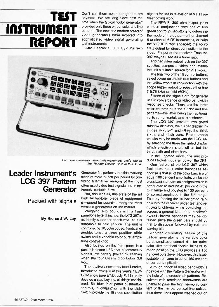
TEST II1STRUMERT
REPORT
Don't call them color bar generators anymore. We are long since past the time when the typical "color generator" provided only three or four color and line patterns. The new and modern breed of video generators have evolved into sophisticated video signal generating test instruments. And Leader's LCG 397 Pattern
For more information about this instrument, circle 150 on The Reader Service Card in this issue.
Leader Instrument's LCG 397 Pattern
Generator
Packed with signals
By Richard W. Lay
Generator fits perfectly into this evolving trend of more punch per pound by pro-viding alternative versions of the most often used video test signals and in ex-tremely portable form. But, this isn't all, this state of the art
high technology piece of equipment is—pound for pound—among the most versatile generators on the market. Weighing 1-1/2 pounds with a front
panel 6-1/8 by 2-1/4 inches, the LCG 397 is as ideally suited for bench work as it is adaptable to field service. The unit is controlled by 10, color coded, front panel pushbuttons, a three position slide switch and a variable color burst ampli-tude control knob. Also located on the front panel is a
power indicator LED that automatically signals low battery power by flashing when the four C-cells drop below 3.6 Vdc. The relatively new entry from Leader,
introduced officially at this year's NEW-COM show (see ET/D, July P. 18) really does go a step beyond, all things consid-ered. Six blue front panel pushbutton controls, in conjunction with the slide switch, provide the 18 video substitution
signals for use in television or VTR trou-bleshooting work. The RF/VIF, 300 ohm output jacks
work in conjunction with one of two green control pushbuttons to determine the mode of the output—either channel 5 or channel 6 RF frequencies, or (with the VIF/RF button engaged) the 45.75 MHz output for direct connection to the video IF input of the receiver. Thus the 397 maybe used as a tuner sub. Another video output jack on the 397
supplies composite video and makes the unit a suitable source for VTR work. The final two of the 10 control buttons
select power on and off (red button) and the yellow works in conjunction with the scope trigger output to select either line (15.75 kHz) or field (60Hz). Fifteen of the signals are for general
use in convergence or video bandwidth response checks. There are the three color patterns plus the 12 dot and line patterns—the latter being the traditional vertical, horizontal, and crosshatch. The LCG 397 provides two gated
rainbow displays, the 10 bar display in-cludes R-Y, B-Y and -R+y, the third, sixth, and ninth bars. Rapid phase checks may be made with the LCG 397 by selecting the three bar gated display which effectively shuts off all but the third, sixth and ninth bars. In the ungated mode, the unit pro-
duces a continuous rainbow on the CRT. One feature of the LCG 397 which
facilitates quick color bandpass re-sponse is that all of the color bars are of equal 100 per cent amplitude, unlike the broadcast standard color signal which is attenuated to around 45 per cent in the G-Y range and boosted to 130 per cent of correct amplitude in the B-Y range. Thus by feeding the 10-bar gated rain-bow into the receiver under test and re-ducing brightness while observing the screen, a general idea of the receiver's overall chroma bandpass may be ob-tained since the green bars should be first to disappear followed by red, and leaving blue. Another interesting feature of this
Leader generator is the variable color burst amplitude control dial for quick color killer threshold checks. In the calib-ration position the LCG provides a 100 per cent burst level. However, this is ad-justable from zero to about 150 per cent of correct amplitude. A rough check of video bandwidth is
possible with the Pattern Generator with the help of the crosshatch patterns. Re-ceivers with restricted bandwidths are unable to pass the high harmonic con-tent of the narrow vertical line pulses,
thus these lines appear washed out on
40 / ET/D - December 1978

the CRT screen under such conditions. The three additional signals available
from the 397 are the unmodulated video carrier and the unmodulated subcarrier. By depressing the blue pushbutton farthest to the right and selecting the sub carrier with the slide switch, a quick calibration check of the unit is possible. (For gated rainbow operation this should be 3.563795 MHz, plus or minus 20 Hz.) Similarly by moving the slide switch to
the upper position, a calibration check of
the unmodulated video carrier is possi-ble (77.25 for Channel 5, 83.25 for Channel 6, and 45.75 for VIF). The 18th pattern available is gray ras-
ter for purity checks. Perhaps the feature that makes the
LCG 397 easiest to use, however, is the scope trigger output which permits triggered input for all pattern displays with rock solid lock in. Priced at $295, the unit is available
with an AC adapter for bench use. ITO
Specifications
PATTERNS:
Offset sub-carrier system 3.563795 MHz ± 20Hz
BURST LEVEL 0 to 150% variable
BAR LEVEL 100% fixed
COLOR BARS 10, 3 and rainbow
CONVERGENCE Dots, intersection of vertical and horizontal bar, white on black background, 15 x 21, 7 x
11, center dot. Crosshatch, white lines, black background, 15 x 21, 7 x 11. Vertical lines, white, black background, 21, 11, 1. Horizontal lines, white, black background, 15, 7, 1. Gray raster, 0% level, black raster. Subcarrier, continuous color subcarrier, no sync.
RF/VIF Output Channel: 5 or 6; VIF Impedance: 3000 balanced Output: 10mv or more
COMPOSITE VIDEO Output: App. 2v p-p Polarity: Negative sync Impedance: App. 10K0
NEW! AN IN-CIRCUIT ELECTROLYTIC CAPACITOR TESTER THAT REALLY WORKS!
The Creative Electronics ESR METER!
(Equivalent Series Resistance)
Checks capacitors from 1 to 10,000 MFD in-circuit , charged or not!
Tells you how close to failure the capacitor is by measuring the dry-ness of the electrolyte - _ it.tsfther reason for electrolytic failures.
Plainly shows up intermittent opens resulting from bad terminations.
Research shows that both problems account for 99% of today's electro-lytic failures. Both can be located instantly with our ESR Meter!
Increases the productivity & profit of the typical service shop by 5%. Patent pending. For free brochure, just send name & address to:
Creative a ctronic4 ESR Brochure
1417 N. Selfridge Clawson, Mich. 48017
Only
$79.50
postpaid
30-day Satisfaction Guaranteed. •
Circle No. 131 on Reader Inquiry Card
DIGITAL MULTIMETER M - 1200
$69.95 Kit $89.95 Assembled
Comparable value $189.00 10 Day Money Back Guarantee
• 3-1/2 digits .56" high for easy reading • High accuracy, 1/2% typical • 10 megohm input impedance • Input overload protection to 1000V • Auto zeroing, automatic polarity • Overrange indication • Low ohms, .01 ohm resolution • AC line operation. Battery optional • measure resistor or diode in circuit
SPECIFICATIONS DC volts Range 200MV, 2V 20V, 200V, 1000V. Resolution .1MV DC Current Range 2MA, 20MA 200MA, 2 amps. Resolution 1 microamp AC volts Range 200MV, 2V 20V, 200V, 1000V. Resolution .1 MV AC Current Range 2MA, 20MA 200MA, 2 amps. Resolution 1 microamp Resistance Range 20, 200, 2k 200k, 2 meg, 20 meg. Resolution .01 ohm
Send check to:
ELENCO ELECTRONICS, INC. 1936 Raymond Drive
Northbrook, Illinois 60062
COD add $2 50 Battery optional add 510 00
for an experience in electronics,
get into cameras
Improve your income by acquiring additional skills as a camera repair technician. Increasing use of elec-tronics in cameras is creating still more opportunities for camera repair specialists. Take advantage.
Performance Training National Camera developed the
first comprehensive technical train-ing for camera repair technicians in the '50's. More practicing techni-cians have received training from us than from any other single source. Now this better-than-ever profes-sional program is as close to you as your mailbox. Learn at home!
Complete Package You get texts, tools, practice
equipment — a complete program including the latest additions in photographic electronics — not available anywhere else.
Free catalog Find out about great training pro-
grams in camera repair technology. You can learn at home, keeping your present job, or at our one-year resident school in Colorful Colorado. For free information, use the cord in this publication or write us today.
0 National Camera
Technical Training Division, Dept. ECA 2000 West Union Ave., Englewood, Colorado 80110
Accredited member: NHSC, NATTS
Circle No. 108 on Reader Inquiry Card Circle No. 119 on Reader Inquiry Card
'ET/D - December 1978 141

DEALER'S SHOWCASE
Stereo High-Fidelity Equip. Circle No. 132 on Reader Inquiry Card
A line of high end stereo high-fidelity equipment is available from Scientific Audio Electronics, Inc. Included in the line are a new power amplifier, the Model 2300; the model 8000 FM stereo tuner; the Model 2900 stereo preampli-fier; and other items of sophisticated
audio equipment, such as the Model 500 impulse noise reduction system. The Model 2300 power amplifier, ac-
cording to the manufacturer's specif-ications, delivers 150 watts per channel minimum RMS power into 8 ohms from 20 to 20,000Hz with no more than 0.05% THD and features full thermal protection, relays to protect the speakers from low frequency damage and elec-tronic protection against transient over-load and short circuits. The Model 800 tuner has a digital
readout, a linear phase IF section which allows stereo distortion of 0.2% or less, a MOSFET front end which produces a spurious response rejection of over 100dB and an IHF sensitivity of 1.6 pv, according to SAE. The Model 2900 preamplifier, SAE
states, features parametric equalization, 0.01% THD and IMD and a phono signal to noise of 90dB (IHF "A" weighted).
The suggested retail price of the Model 2300 is $700. The Model 8000 is $700. And the Model 2900 is $500.
Audio Cabinet Circle No. 133 on Reader Inquiry Card
Gusdod offers a new unit of electronic furniture intended to house audio com-ponents. It has four adjustable interior shelves which can accomodate most types of equipment. The lower section of the cabinet is storage compartments with slide up doors and removable rec-ord dividers. The full back has access holes with removable plugs to organize
connecting wires. The Model #1435 stands 48 in. high, the left compart-ments are 233/4 in. wide, the right com-partments are 191/2 in. wide and the compartments are 191/2 in. wide and the unit is 17 in. deep. The retail price is approximately $144.
Time Lapse Video Recorders Circle No. 134 on Reader Inquiry Card
RCA Closed-Circuit Video Equipment has announced two new time lapse re-corders for closed circuit TV security
systems. The recorders, the standard TC3250 with an internal time/date generator and the low-cost TC3200 without this feature, use 1/2 in. VHS cassettes instead of the reel-to-reel' tapes used previously in most such sys-tems. Both models permit the user to
select any of 50 different record/ playback speeds, permitting a maximum recording time of 200 hours at the slowest speed. The TC3250 model in-corporates controls that position the time/date display on the screen and also control with width of the display. An
alarm memory stores the time and date of an alarm, automatically displaying this information when the recorder is stop-ped. Thus, recorded events at specific alarm times can easily be located and reviewed. A remote alarm can trigger a change in recording speed to any of four pre-selected rates. Switches also permit the user to choose alarm duration, as well as any of 15 camera switcher pulse
rates. Both models will be available at optional user prices of $3090 for the TC3250 and $2775 for the TC3200.
Preassembled CB Beam Circle No. 135 on Reader Inquiry Card
Channel Master has introduced a new CB beam called Signal Tracker. The Signal Tracker is a high efficiency beam made of drawn aluminum tubing. The company claims it can be completely assembled and ready for mounting in less than ten minutes. It has a boom length of 12.0 ft. Channel Master claims it has a 13.5 db gain over an isotropic source and front-to-back and side sep-aration of 30 db, thereby outperforming beams up to 25% greater in length. It is gold EPC coated for weather protection and can be adjusted for optimum perfor-mance on a desired channel, covering all forty channels. The Model 5059's price is $79.95. ETD
42 / ET/D - December 1978

— 101-416 p. (8,2"x11") —Electronic Circuit Design HandboOk- ($17 95)
ELECTRONIC CIRCUIT DESIGN
HANDI30°K
isArna zegnitj lisiA3"
@OG WOITg 601-392 p.—Master Handbook of -Ism Radio Circuits ($12.95)
1012420p.—Flow to Design and Pend Sectroric Instru-mentsiOn ($14.95)
Niaviso
An Extraordinary Offer to introduce you to the benefits of Membership in
ELECTRONICS BOOK CLUB any r ALL
for
electronics books take of these 22 unique
(values to$67") for only FOUR with a Trial Membership in the Book Club that guarantees to save you 25°0 to 75°0 on a wide selection of electronics books
•
691-196 p.—Practical Solid-State DC Power Supplies ($9.95) 10112-31)2 p.—First Class
Commercial FCC License 11 Study Gonda (II12.95)
7019294 a. Modern Guide to Biol. MI Logic. Processors, Memories 8 Inierfacm (69.95)
-1.911;A
995-182 p.=Beginner's Guide to Microprocessors ($8.95)
971-196 p.—MIriproces-son: Frcm Calculators to Computers ($9.95)
997-432 p.—The Handbook of Tele-phones I Accessories (1114.95)
O v j0•14 M P.,
INSTRUMENTATION ‘,Ttsfs CONTROL SY
1035-434 p.—Instrumentation Control Systemic Engineering Handbook ($19.95)
1036-140 pa—How To Cut Your Electrical BIN I Install Your Own Emergency Pager System ($6.951
co„v,„ !
Electrical & HOUSe Wiring !I
743-224 p.—Electronic Music Circuit Guidebook ($9.95)
9134711 p.-1114) Complete Handbook of Electrical I House Wiring (910.95)
1174-392 p.—Master Handbook of Digital Logic Applications ($12.95)
919-434 p. —Color TV Trouble Factbook-Problerns I Solutions-3rd Edition ($9.95)
Facts About Club Membership • The 4 introductory books of your choice carry publishers retail pricesof up to $67 80 They are yours for only $1 99 for all 4 (plus Postagehandling) with your Trial Membership • You will receive the Club News, describing the current Selec lion. Alternates, and other books. every 4 weeks (13x a year) • If you want the Selection do nothing. it will be sent to you automatically (1 you do not wish to receive the Selection. or if you want to order one of the many Alternates offered, you simply give instructions on the reply form (and in the envelope) provided and rekrn it to us by the date specified This date allows you at least 10days in which to return the torn If because of late mail delivery you do not have 10 days to make a decision and so receive an unwanted Selection you may return it at Club ex-pense • To complete your Trial Membership. you need buy only four irlditioral monthly Selections or Alternates during the next 12 months You may cancel your Membership any time after you Purchase these four books • All books—including the Introductory Offer —are fully return-Ale after 10 days if you re not completely satisfied • All books are offered at low Member prices, plus a small
postage and handling charge • Cantailling Bones If you continue after this Trial Membership. you will earn a Dividend Certificate for every book you purchase Three Certificates plus payment of the nominal sum of $1 99 will entitle you tc a valuable Book Dividend of your choice which you may choose trom a list provided Members
800-602 p—Master Hand-book of 1001 Practical Electronic Circuits ($12.95)
NR, ay we send you your choice of 4 of these practical time-and-money-saving books as part of an un-
usual offer of a Trial Membership in Electronics Book Club?
Here are quality hardbound volumes, each espe-cially designed to help you increase your know-how, earning power, and enjoyment of electronics. What-ever your interest in electronics, you'll find Elec-tronics Book Club offers practical, quality books that you can put to immediate use and benefit.
This extraordinary offer is intended to prove to you through your own experience, that these very real advantages can be yours...that it is possible to keep up with the literature published in your areas of interest, and to save substantially while so doing. As part of your Trial Membership, you need purchase as few as four books during the coming 12 months. You would probably buy at least this many anyway, with-out the substantial savings offered through Club Membership.
To start your Membership on these attractive terms, simply fill out and mail the coupon today. You will receive the 4 books of your choice for 10-day inspection. YOU NEED SEND NO MONEY. If you're not delighted, return the books within 10 days and your Trial Membership will be cancelled without cost or obligation.
ELECTRONICS BOOK CLUB, Blue Ridge Summit, Pa. 17214
Circle No. 107 on Reader Inquiry Card
1017-140 p.—Understanding Sound, Video, and Film Recording ($8.95)
sm.
24 TE511 11 RuN 6AME REAOY"'' IN 8A G O MIS
How ts,° 1 519n n 6
Duid tom Tc't)* Goma, TV Cob 1101-546 p How to Design Build Your Own Custom TV GeMilf 014.951
Nor to Solid
Metal/Tromso.* Locators
..4•••••
909-140 p.—How to Build Metal , Treasure Locators (S7.95)
1085-252 p.-24 Tested, Ready-To-Run Game Programs in BASIC ($9.95)
1. rf 106 EASY
ELBEeEyToRnOd Nt hi CeS TPraFtn°1 T irsCt otS
By Rufus P Tuort
687-244 p-106 Easy Elec-tronics Projects —Beyond the Transistor ($8.95)
715-294 p.—liticropro-ceemorrillitcreprogrammIng Handbook ($9.95)
I ELECTRONICS BOOK CLUB
•
Blue Ridge Summit, Pa. 17214 Please open my Trial Membership in ELECTRONICS BOOK CLUB and send me the 4 books circled below. I
understand the cost of the books I have selected is only Si .99 for all 4. plus a small shipping charge. If
not delighted, I may return the books within 10 days and owe nothing, and have my Trial Membership
cancelled. I agree to purchase at least four addi-tional books during the next 12 months after which I
may cancel my membership at any time. 101 709 743 785 800 801 874 887
891 909 913 919 971 995 997 1012 1017 1035 1036 1085 1092 1101
Name Phone
Address
City
State Zip 'Valid for new Members only. Foreign and Canada add 10'01 T-128
ET'D - December 1978 I 43

new PRODUCTS
Combination Microphone and Speaker Circle No. 136 on Reader Inquiry Card
The same miniature transducer in user's ear can be used as a microphone and a speaker with The Ear Com system available from the Electronic Instrumen-tation Division of Lear Siegler, Inc. It al-lows hands-free, two-way communica-tion in high ambient noise situations. The manufacturer states it is being used by SWAT teams, refinery and chemical plant workers and fire fighters as well as under cover and surveillance work by police agencies.
Time Marker Generator/Sweep System Circle No. 137 on Reader Inquiry Card
A low cost, time marker frequency sweep generator for commercial, edu-cational, or hobby use in calibrating os-cilloscopes is being introduced by A. E. Corp. of Needham, MA. The Time
Marker frequency sweep generator lets an oscilloscope simultaneously display
the amplitude of a sweep signal at a number of different frequencies marked by a calibrated reference reticle. It is ad-justable from 1hz to 100khz in factor of 10 increments. The A. E. Corp. Time Marker frequency sweep generator consists of a Model 12 sweep function generator and a Model 20 pulse generator linked by a Ramp and Marker interface. The Models 12 and 20 may be used independently and, if desired, a
clock or oscillator may be substituted for the Model 20. The A. E. Corp. Time
Marker frequency sweep generator re-tails for $155 (kit) and $240 (assem-bled). The Model 12, Model 20, and
Ramp and Marker interface are also of-fered individually.
Mobile Towers Circle No. 138 on Reader Inquiry Card
Aluma Tower Company has introduced a new series of "Mobile Van Towers" for
communications and test work. The manufacturer states the towers can be mounted on a standard ladder rack on top of a van, tilted to a vertical position and cranked up to the desired height easily by a single operator. Several models are available including two in-tended for use with internally mounted rotators.
Resistor Storage Box Circle No. 139 on Reader Inquiry Card
LOWCO Engineering's model RS-144 resistor selector box provides separate storage for 144 resistor valves, with "in-
stant" visual inventory of all resistors. Ten to twenty-five resistors will fit in each
of the 144 compartments, depending on whether 1/4, Y2, or 1 watt carbon or car-bon film resistors are stocked. All com-
partments are individually pre-marked with the 5% range from 10 to 990K0. The size is 14 x 14 x 3". The price is $4.75. Stocked with 1440 carbon film resistors, 10 of each value, the price is $79.45.
Wire-Wrapping Kit Circle No. 140 on Reader Inquiry Card
A new wire-wrapping kit for the pro-
totype builder or hobbyist is available from OK Machine and Tool. The kit in-cludes the Model WSU-30, a combina-tion wrap-unwrap tool and stripper for 30AWG wire, and a 50 ft roll, plus as-sorted 1 to 4 in. lengths of 30AWG Kynar insulated silver-plated copper wire. Wire colors available are red, blue, yellow and white The kit is priced at $12.95.
Digital Multimeter Circle No. 141 on Reader Inquiry Card
Sinclair Radionics has recently intro-duced a new bench portable digital mul-timeter, the DM235. This 31/2 digit LED display meter is intended for portable use according to the manufacturer who states it weighs 11/2 pounds and is only 11/2 inches thick and operates on 4 "C" cells with a rechargeable battery pack and an ac adapter/charger available as options. The price is $89.95.
44 I ET ID - December 1978

VIZ TEST INSTRUMENTS" :01,!, 11111111111 11 .4‘
• All pallor,. output 1413 IF
Vgleo 75• • or M O
• Cm o...r.0, az,frehmt..a.r
h•tch bl•nk r•ster
• Profesaronal super•
Pulse while vundo•
Col or T. V. P att er n srgnal tor over-all re Ceiver •••,, ,is with
Generator sync control
• II:Mall , MATS CATS CC iv ... MR-51 5A
•0112 MI OUR PRICE $169.15
Audio Sine Sq. - Wave Generator
-„, WA-504B/44D
In 4 ranges slats., tortron 0 •
t o. rris• •nd tall 150 n• r
0 03 ,0 ,00 0. 000 .. • All solid-state through
Reg SI29 95 oul Voiff •C [Old
OUR PRICE $110.50
0
Scope Dual-Tracer
..„„WM-54 1 A
• tunabie on lundamentm
6 ranges 65 kHz to 40 MHz r. rm. •seep
output al 455 kHz and
tO 7 MHZ plus E•ternal Hal
• Co mer, song. trace
SCOpe to dual trace
• Fres response DC to 4
3011 rnput "op 1M• • shunted by 45 pf
• Choice ol ranee'', a, tern•le or chopped
F*11ch . 2 5 retro ettenuators
CMOS orcurtry BNC
connectors S108 00 OUR PRICE
91.80
AF Signal Generator
WR-50C • Sr outs., 0 Us, rrnk 2
slep 10 to 1 plus fine adl
ane mia ., ficti 03)002
• enc:i7 Zs r•I'O'Vr:79 " " OUR PRICE
• Aud.o Output 6V r.T $102.00 IS k• • Prod
• PET 3.1 stabady 3 *se AC cord
COLOR PATTERN GENERATOR 500(2
WR-50813 S,41I0 OUR PRICE $59.95
• Latest IC circuits. rehab,* glass
circ011 board • Provides Pa m lest palter .
• Compact. small tor pOrtebiltly • Swoon's from AC•line to battery • E 'table ollmr•tiOn
• Lovr COST, N O performance • Output on Ch 3 .001 to Cr, 20,4
M O W'
Color B&W Picture Tube Tester Restorer Req. $249 95
OUll PRICE
- WT-333 B $175.00
• Complete Al . 5 socket 11.1.001 ,• mcluMng 1,101flype
• E•sy to use compact rug
god ABS pl . . D OD
• 3 meter de•sn pernnts an
three guns of color pif tube lobe tested sgnullan•ously
• Ettettgre 1alhode•ensssion
restorer adds to •••11
0.• tubes
Ruggedized Color Bar Generator
• --•,---•e•e lough glass PC board
shock mounted It•S•rn oper temp 5 F to
145 F
• 100, tbsirlalI C crystal
control
• Color . . oil, 1•01•010
dots crosshatch Super
Pus• and sy m control 2 line AC ord
Reg SI30 II)
OUR PRICE
$75.00
Senior VoltOhmyst •
..WV-98C • • 2 color meter race and
panel lor pos.!, tunchon
st•nhIsairon peak . peek
• Meier •lectronsally prO• • 7 • 0 OUR PRICE •nd rms scales
tected agmn•I ov•rload
• liespon•• to 2 MIS4 /11A• •
input revs's''' . • Measures front 0 2- 001
• DID cast aluminum Case VDC 005 VAC to 1000M! .
• Ea•y to read 6.3 116 4 col 1500 .11s DC •nd AC V. rmeror•scals nwler accuracy aft Notch:T.
$118.00
Master VoltOhmyst • Irns AC vol. on 7 ranges
nom 02 10 1500
APtI 5 SP1R619CE • - 10A ;,1R $143.50 lo 4200
_ • Esc•Ilent Walsh. • 21 megolun ntsistance on
all DC ranges F S • • Battery or AC of. . .. accuracy all funcbon
• Iktle•sures from 001 nig Supplied with DC •C Ohms
5 .. .. 7•S .1` probe err. nest,* sluelde0 ranges rnput C•••• INC counts
• Measures from 0 2 pnm• torl and current lest loads
t. 1000 megohms in 7 r•nges • Mirror scale Meter--
• Me msges from 0 01 volt to 0,00 . . 0, ett1C .C•SS Pro•
,soo .00s pc 01 floOr. Mdled 60,0°.
15 MHz. Trigger Sweep Scope WO-527A • ref, reap DC to IS MOO I 2 453 ••n•oto.dy to fovccv4 to 20V m I t•og•e Rose mne 23 o sec Mom 0•0 free, DC IS IMM:
• Trigger mode norrnai or auto freq rmp DC to 30 PAH,
• C•10,I•t•• 11•1• •••• 0 5-sec to 0 5 sec . to wipes
• Preset TVV and TVI4 plus
• di o 0 OMNI spec.al TV im• selector 10 ell•play song's. Imo 01 TY video Pam.
•• • Times tO eeeee M•g •d Reg ••nced t. C cleculiry OUR PRICE S459.25 NH W eld I • 10 cm CRT pita
I•31 Ph0s
CODEA-PHONE
Telephone Answering Devices VViremote
• Command "Vii4
Model 1400 $199.95
31/2-Digit Portable DMM al',1( CISION
S85 $110.50
Model 15 0
15 MHz Mini Oscilloscope Model MS 15
Reu S318 00
$269.95
M N AVAILABLE Uual 1 tate wriKoun t 369 .9 5
Model MS 215 CI-0 "
ea $40.00
SJ C.; CD
POCKET CRICKET 1RANSISTOR PEI TESTER
".. $99.95 TE 40
Auto Stereo 40 Watt Power Booster POW-40 S24.95
Quick Tracer Transistor/Diode
• Raold check of in. or out-of -Circuit
transiatore and dicide•
• Usia with ger m & purpose oscilloscope
$19.50
E r'r•J CC DF= T E
TV-VTR-MATV and Video Analyzer
$249.95 01
Ungar Heat Gun
$46.5 Welter % Xcelite'
$875.00
FORDHAM YOUR ONE STOP DISCOUNT CENTER
CV rn
CONTINENTAL SPE
100 MHz 8-Digit Counter $119.00-
"°"''' PS500 500MHZ Prescaler $52.9 : 1( PRECISION Digital Capacitance Meter
Mod,' 8/0
110.50
U E A DER
Before you buy, check our prices... Call TOLL FREE (800) 645-9518
N V State call (51 61 752-0050
VISAMaster ceR rc a ararad
C 0 D S accepted
000 MAP 100
TransistorizedIBSR Changer LCR Bridge 'Accessories Mode! ECR,/40 \ $24.95
w $271.95
WAHL NEW ISO-TIP "Quick Charge'
Logic Monitor = M = S27.95 Model /500 Curdle,
odri ,,,, Soldenng bur $17.95
KAl '.-, $52.95.-, , Model 5800 Theta. So Service Master Attache Style -
Witt c tcolt Tesiet $22 50 HI CK O K
Tool Kit To Model 99SM MO oM 1l IC 100 ST --' 98'4 Attach ' $42.95 $269.95 Roll Kit 15.95 CaseLith:
with 2 U • Removable Pallet
'''''''°T $65.00
L E A DER Inelruonnen . C O•P
20 MHz. Dual Trace
S654.50
VOM Multi meters 20K ohm/v $19.95
1K ohm v 9.95
jel(PRECISIOIll
SUPER SPECIAL
182,
$59.95
In-Dash
AM/FM 8 Track Stereo C 777
$52.50
Function Generator
7,0 s'169.15
Sub-stitution Box $51 Model 2910
I'rsoil IP 6" x 9" ou 3-Way
Speaker
$14.95
MODEL
7800
PRECIS/ 15MHz 3" Dual Portable Trace Scope
14328 k
S663. -
Weller Controlled
$45 .° Outptit
7:4 AM/FM Call TOLL FREE
30MHz Cassette (800) 645-9518 Portable CAS 888 Stereo 1 - ..... ...„....,......... Frequency , $57 .50 VISA
Counter Transistor Tester $22.00
m'-' FORDIIIMA.
heck out pneet
Soldering mode'w Station FREE
1979 Catalo
ta mngdale N C - •
Circle No. 142 on Reader Inquiry Card
ETID - December 1978 / 45

CLASSIFIED RATES: 40 cents per word (minimum charge, $10). Bold face words or words in all capital letters charged at 50 cents per word. Boxed or display ads charged at $50 per column inch (one inch mini-mum). For ads using blind box number, add $5 to total cost of ad. Send ad copy with payment to Dawn Anderson, ELECTRONIC TECHNICIAN/DEALER, 1 East First Street. Duluth, MN. 55802.
BOX NUMBER REPLIES: Mail box number replies to: ELECTRONIC TECHNICIAN/DEALER, Clas-sified Ad Department, One East First Street, Duluth, MN 55802 Please include box number in address.
FOR SALE
SONY-PANASONIC-RCA-ZENITH-EXACT REPLACEMENT PARTS-LARGE INVEN-TORIES-SEND PART OR MODEL NUM-BERS-WILL UPS COD-GREEN TELE RADIO DISTRIBUTORS, 172 SUNRISE HIGHWAY, ROCKVILLE CENTRE, N.Y. 11570 5/79
FOR SALE: COLOR PICTURE TUBE RE-BUILDING EQUIPMENT SEMI-AUTOMATIC ELECTRONICALLY CON-TROLLED PROCESS. Call or write Atoll Television, 6425 Irving Park, Chicago, IL 80634 Phone 312-545-6667. 11/7a
TELEPHONES UNLIMITED, equipment, supplies, all types, regular, decorator, keyed, modular. Box 1147T, San Diego, California 92112. 4/79
TRANSISTOR REPLACEMENT. PHYL-TRON ELECTRONICS LX REPLACEMENT LINE REPLACES THE MOST POPULAR REPLACEMENT TYPES AT OR BELOW DISTRIBUTOR COST. One year uncondi-tional guarantee. Buy direct and save. Write for free catalog. Phyltron Electronics, 487 Springfield Ave., Summit, N.J. 07901. IF
ELECTRONIC BARGAINS, CLOSEOUTS, SURPLUS! Parts, equipment, stereo, indus-trial, educational. Amazing values! Fascinat-ing items unavailable in stores or catalogs anywhere. Unusual FREE catalog. ETC0-013, Box 762, Plattsburgh, NY 12901. IF
GET OUT OF THE TV RUT Start making money now with Paltronix por-table security systems. No technical hassles to keep up with. Full training provided. Good margins to work with. Plus your chance to diversify your services. For full details contact Don Musil, 48 West Golden Lake Road, Cir-cle Pines, MN, 55014 (612) 786-4244. 9/78
Save hundreds: dependable, quality Head-Ends, V/V, U/V Converters, Camera Mod-ulators. Factory prices. Send $5.00 (or busi-ness card). "Information," Box 809, Boynton Beach, FL 33435. 12/78
PICTURE TUBE MACHINE We buy and sell NEW AND USED CRT re-building machinery. COMPLETE TRAINING Buy with CONFIDENCE from the ORIGINAL MFGR. For complete details. send name, ad-dress and zip code to:
LAKESIDE INDUSTRIES 4069-71 N. Elstone Ave., Chicago, IL 60618
Phone: 312-583-6565
TUBES-Receiving, Industrial and Semi-conductors, factory boxed. Free price list. Low, low prices. TRANSLETERONIC INC. 1365-39th Street, Brooklyn, N.Y. 11218E 800-221-5802, 212-633-2800. 4/79
REPLACEMENT COLOR YOKES-DEAL-ERS ONLY. Zenith 95-2501-2532-2638-2667-S89633 etc. $16.95. Magnavox 361380-1 $18.95 etc. Sylvania, G.E. etc. $14.95 to $19.95. Request for price list on your letterhead. David Sims Enterprises, Inc., 665 Jerricho Turnpike, Huntington Station, N.Y. 11746 IF
GENUINE SONY SEMICONDUCTORS-CHECK THESE PRICES!! EG. 1-9/ 10-24-SG613-8.50/7.30-SID 30-15 2.60/2.30, -2SC867A 5.10/4.90-2SC1114 5.50/4.80-2SC1358 6.50/5.70, -2SC1124 1.50/1.30-2SC634A 0.45/0.41. Contact us for complete list of Japanese semiconductors and pricing information. Bescor, 547 S. Broadway, Hickville, NY 11801 (516) 822-3988 IF
REPAIR TV TUNERS-High earnings, Com-plete Course Details, 12 Repair Tricks, Many Plans, Two lessons, all for $2. Refundable. Frank Bocek, Box 3236, Ent., Redding, CA 96001. hF
Electronic Technician/Dealer 1966-1978, PF Reporter/Electronic Servicing 1965-1978. $35. each or best offer, plus freight. Moraga TV, 1480 Moraga Rd., Morago, CA 94556. 12/78
MATV-CATV INSTALLERS Get lowest prices on antenna accessories, fastest service from ANTSCO CORPORA-TION. Call collect, ask for catalog & prices. All orders shipped same day. Sierra Madre, CA 91024. 213-355-2510. 2/79
LINEAR AMPLIFIER, 2-30 MHz, 150 watt solid state. FREQUENCY COUNTER, 300 MHz, 7 digit portable/mobile. OMNIPOLAR-IZED BASE ANTENNAS. Modulation boost-ing VOX-COMPRESSOR. Construction plans $3.00 each $10.00/all. Others! Catalog with order. PANAXIS Productions, Box 130-ET10, Paradise, CA 95969. IF
TV AND RADIO TUBES .360 EA!! Send for free color parts catalog. Your order free if not shipped in 24 hours. Cornell Electron-ics 4215-17 University San Diego Califor-nia 92105. IF
Complete color, b/w picture tubes rebuilding equipment. Never used. Phone (212) 387-2744, Brooklyn, NY 11211. #FLOE3085063-02. 12/78
BUSINESS OPPORTUNITIES
Sales & service for RCA plus authorized ser-vice for Zenith, Quasar, Nu-Tone Products, closed circuit and master antenna service. $35,000 total price includes $12,000 inven-tory. Good terms. Over $30,000 net to owner. Contact Dean Vincent, Inc., 1445 Willamette St., Eugene, Or. 97401.
Vermont Radio-TV Sales & Service. Long es-tablished, owner retiring. Business $175,000, w/R.E. $275,000. Details to qualifed princi-ple(s). Marble City Realty, Box 265, Rutland, Vermont 05701.
T.V. Sales & Service Business, in Florida. Zenith & RCA Franchise. $15,000 cash. Write to: Mr. Jose A. Paredes, 2427 5th Ave. North, Saint Petersburg, FL 33713.
BROADCAST STATION. Start your own, any type! Unique Cable FM station requires no investmenVexperience. Receive free tapes, records. Learn how. Free details. "Broadcast-ing," Box 130-ET10, Paradise, CA 95969.
TF
TV TECHNICIANS AND DEALERS, "IN-CREASE YOUR INCOME" thousands of dol-lars yearly! "Rent-Lease-Sell TV's." Easy to start or add to your present operation. 'Guaranteed complete basic plan and starter kit," $15.00, or stamped envelope will get you free details. Perry's TV Leasing Systems, Box 1407, Santa Maria, Calif. 93456.
Television, stereo dealers-Increase gross income $50,000 without increasing over-head. No additional investment or personnel required. Free details, Carank EM Box 7696, Naples, FL 33941. 1/79
"Rent Lease TV's anyone can!" Easy to start and operate. Even from your home. Send $2.00 for basic information. Perry's TV, P. 0. Box 1407, Santa Maria, CA 93454. 1/79
TV Sales and service, shopping center, sub-urb near San Francisco Bay, seven years. Completely equipped including late Dodge van. Excellent growth potential. Owner retir-ing. $18,000 buys lease and all. Principals only, no shoppers please. Mornings (415) 376-3796. 12/78
For Sale. RCA TV & Appliance, Sales & Ser-vice. Nest North Dakota. Established 10 yrs. Over 115k gross average last 3 yrs. Other interest forces sale. Expanding town in en-ergy area. Excellent Opportunity. Would con-sider partner as future buyer. Write R. Roach, P.O. Box 783, Watford City, N.D. 58854.12/78
MECHANICALLY INCLINED INDIVIDU-ALS-BUILD ELECTRONIC DEVICES IN YOUR HOME. GET STARTED IN YOUR SPARE TIME. $300 TO $600/WK POSSI-BLE. EXPERIENCE NOT NECESSARY, WRITE FOR FREE LITERATURE. ELEC-TRONIC DEVELOPMENT LAB., BOX 1535 (B), PINELLAS PARK, FLA., 33565. IF
TV Business Located in Hompton, Va. $18,000 including Trucks & Inventory. Estab-lished 5 years. Great Potential. Call Alexon-der Realty, 34 West Queens Way, Hompton, Va. 23669. (804) 723-1303. 2/79
MOVING TO FLORIDA? TV SERVICE AND RENTAL BUSINESS FOR SALE ON FLORIDA'S WEST COAST. DOING $40,000 - $50,000 PER YEAR. ALL REASONABLE OFFERS CONSIDERED, ALSO BUILDING AVAILABLE. CONTACT: MR. SOTHERN, 1-813-535-2026 AFTER 7 PM OR WRITE: 1834 SUNRISE BLVD., CLEARWATER, FLORIDA 33520 TF
46 / ETID - December 1978

HELP WANTED
ELECTRONICS/AVIONICS EMPLOYMENT OPPORTUNITIES. Report on jobs now open. Details FREE. Aviation Employment Informa-tion Service, Box 240Y, Northport, New York 11768. 8/79
Earnings over $20,000 a year to top outside Technicians. Qualifications: 15 years experi-ence, absolute honesty, non-drinker, non-smoker. Benefits: group hospital plan, paid vacations, reimbursement for moving, excel-lent area to raise families, outdoor sports paradise. Send resume to American Televi-sion, 1032 South State, Orem, Utah 84057.
WANTED
WANTED: PICTURE TUBE REBUILDING MACHINE, working or not. Call or write: Atoll Television, 6425 Irving Park, Chicago, IL 60634. Phone 312-545-6667. Hours 1-8 PM. 11/78
Wanted: Modulation or deviation meter for 100 watt 45 MHZ FM transmitter. New or used. John Collins, 3015 Chambers Circle, Colorado Springs, CO 80904.
Where there is HOPE... there is life.
(;ne to
PROJECT
Department A, Washington, D.C. 2000"
AR Semiconductors Exact ECG Replacements *
ECG NO.
DEALER COST
SUGG. RESALE PRICE
ECG DEALER NO. COST
SUGG. RESALE ECG DEALER PRICE NO. COST
SUGG. RESALE PRICE
100 .85 1.60
,
161 .95
_
1.60 225 4.29 5.67 101 .90 1.76 162 4.40 8.40 226 1.75 2.92 102 .87 1.58 163A 5.95 10.75 228 1.15 1.31 102A .92 1.68 164 4.50 8.40 229 .90 1.53 103 .99 1.84 165 7.25 13.50 230 3.40 5.11 103A 1.09 1.90 166 .95 1.68 231 4.00 5.85 104 .97 1.60 167 1.10 2.05 232 .59 .98 104MP 1.94 3.20 168 1.26 2.25 233 62 1.02 105 2.45 4.22 169 1.84 3.05 234 .57 1.00 106 .52 .95 170 2.75 4.95 235 3.50 6.30 107 .68 1.35 171 1.25 2.15 236 6.25 10.40 108 .85 1.53 172A .50 .90 237 4.60 8.10 109 .24 .33 173BP 4.30 6.54 238 12.25 15.75 110MP .32 .54 175 1.25 2.25 239 2.75 3.63 112 .55 .87 176 2.21 3.94 241 1.35 2.29 113 .35 .60 177 .50 .90 242 1.55 2.52 114 .35 .60 178MP .54 .95 243 1.85 2.69 116 .38 .66 179 5.01 8.88 244 2.60 3.63 117 .35 .60 180 4.98 8.84 245 3.10 4.40 118 1.35 2.95 181 4.15 7.50 246 3.95 4.77 120 .55 .90 182 2.90 4.40 247 3.25 4.77 121 1.70 3.18 183 3.25 5.00 248 4.50 6.42 121MP 3.40 6.36 184 1.10 1.99 249 5.65 8.38 122 1.80 3.30 185 1.30 2.29 250 5.95 8.50 123 .59 1.05 186A 1.30 2.29 251 5.90 8.38 123A .70 1.32 187A 1.45 2.50 252 5.95 8.50 124 1.20 2.30 188 1.20 2.20 253 1.45 2.06 125 .45 .79 189 1.30 2.50 254 1.60 2.41 126 1.02 1.85 190 1.70 3.10 261 1.50 1.95 127 3.90 7.50 191 2.10 3.80 262 1.65 2.16 128 .99 1.75 192 1.00 1.80 263 1.50 1.95 129 1.10 1.85 193 1.05 1.86 264 2.25 2.93 130 1.95 3.80 194 .55 1.05 274 2.40 2.80 130MP 3.80 7.60 195A 2.40 3.95 280 4.20 6.30 131 1.75 2.84 196 1.65 2.70 281 5.40 8.20 131MP 3.50 5.68 197 1.60 2.52 282 4.50 6.45 132 .88 1.60 198 1.58 2.65 283 6.75 9.40 133 1.00 1.80 199 .46 .81 284 6.70 10.10 152 1.20 2.20 210 1.15 1.99 285 7.30 10.95 153 1.30 2.50 211 1.35 2.29 286 6.70 8.20 154 1.85 3.30 218 3.10 5.25 287 60 .86 155 1.95 3.42 219 3.25 6.49 288 .65 .93 156 .70 1.30 220 1.40 2.50 289MP 1.70 2.20 157 1.10 2.15 221 1.50 2.68 290 .99 1.26 158 .99 1.86 222 1.80 2.90 291 1.70 2.49 159 .89 1.53 223 2.75 3.78 292 1.95 2.82 160 1.34 2.16 A 224 4.50 8.10 _ 500A 10.50 18.00
2 Year Unconditional Warranty • Same Day Shipping • No Minimum Order • Prepaid or C.O.D. Accepted 'Orders over $25.00 shipped free, under 625.00. add $1.00 UPS
AR Semiconductors, P.O. Box 976, Union, N.J. 07083
send a message... ...write here.
1. Number of insertions: (circle) 1 2 3 6 12 2. Start with (month) issue (Copy must be in by 1st of month preceding)
3. Amount enclosed: $
PAYMENT MUST ACCOMPANY ORDER. WE'LL BILL RATED FIRMS
NAME COMPANY
STREET
CITY STATE ZIP
MAIL AD COPY TO: DAWN ANDERSON, ELECTRONIC TECHNICIAN/DEALER, 1 EAST FIRST STREET, DULUTH, MN. 55802. RATES: 40 cents per word(minimum charge, $10). Bold face words or words in all capital letters charged at 50 cents per word. Boxed or display ads charged at $50 per column inch (one inch minimum). For ads using blind box number, add $5 to total cost of ad.
ET ID - December 1978 I 47

READER SERVICE INDEX
ADVERTISER'S INDEX
101 Antennacraft
127 B & K Division Dynascan Corp.
121 Cornell Electronics
131 Creative Electronics
114 Hickok Electrical Inst. Co. 11
115 JFD Electronics Corp. 27
116 MTI 26
36 117 Mallory Distributor Product Co. 7
33 118 Modular Electronics Services Ltd. 26
18 119 National Camera (NCTTD) 41
41 120 New-Tone Electronics 8
106 Devco
107 Electronics Book Club
108 Elenco Electronics
109 John Fluke Mfg. (for info)
110 John Fluke Mfg. (for demo)
142 Fordham Radio Supply Co., Inc.
Fuji-Svea Enterprises
112 GTE Sylvania EGC Consumer Renewal
113 GTE Sylvania EGC Consumer Renewal
General Electric, TV Business Div.
General Electric, Tube Div.
General Electric, Tube Div.
The next time you need a tuner repaired or module rebuilt:
Remember FAST SERVICE
Remember PROFESSIONAL QUALITY
Remember
ONE-YEAR LIMITED WARRANTY Remember PTS ELECTRONICS
PTS ELECTRONICS, INC. SEE THE YELLOW PAGES FOR THE
PTS SERVICENTER LOCATION NEAREST YOU
4 PTS Electronics, Inc. Coy. 2
43 122 PTS Electronics, Inc. 1
41 123 PTS Electronics, Inc. 48
15 124 Sentry Manufacturing Co. 38
15 125 Texas Tuner Service 8
45 126 Texas Tuner Service 18
3 104 Triplett Corp. (for info) Coy. 4
19 105 Triplett Corp. (for demo) Coy. 4
35 128 Tuner Service Corp. 16
39 129 VIZ Manufacturing Co. 18
5 130 Workman Electronic Products Inc. 37
23 103 Zenith Radio Corp. Coy. 3
George V Eltgroth is a Patent Attorney for General Electric. He is legally blind.
Circle No. 123 on Reader Inquiry Card 48 / ET ID - December 1978

There's no waiting or turn-around time when you bring Zenith modules, tuners or sub-assemblies needing repair to your Zenith distributor.
That's bench strength for you—as deep, depend-able, and easy to draw on as any you'll ever know.
Not only will the faulty component be replaced, but the replacement module will have been up-dated to incorporate the latest factory technical improvements.
And it's an over-the-counter exchange. You walk out with a Zenith factory repaired and re-conditioned replacement serviced by the same people who made the original.
So it simply makes good sense to exchange your modules, tuners, and sub-assemblies with those from the original source.
That's with your Zenith distributor, of course, for modules, tuners and sub-assemblies.., and Ebench that never quits!
For your own reputation and In your customers' best interest, always specify Zenith exact replacement parts and accessories,
ON/171 The quality goes in before the name goes on
There are times he'd give anything to draw on a bench as consistently strong, deep, and versatile as Zenith's!
Notre Dame basketball coach, "DIGGER" PHELPS
Circle No. 103 on Reader nquiry Card
Zenith Radio Corporation /Service, Parts & Accessories Division /11000 Seymour Avenue/Franklin Park, Illinois 60131

THE NEW
erfornier• Model 3400 has features that upstage other compact DVOMs.
L TRIPLETT MODEL
DC 'II AC
0'. O W ; le•
Ote
-4 .11 SO
Tn •
tint to fit your hand and budget, the new Model 3400 (shown actual size) is loaded with features. Like a color coded single range switcn for one-hand selection of all functio ... overload protection for all ranges and 2 hour minimum battery life ... time-saving automatics Including auto-zeroing, auto-polarity, auto low-battery and auto-overrange indication ... easy to read .5"LCD readout.
Six functions and 24 ranges, typical DC accuracy .5% Rdg, Including High and Low Power Ohms for sensitive IC testing, makes the Model 3400 ideal for iesign, production and maintenance testing vocational tech training schools. cornme -cial electronic equipment test and measurement use.
1. HAND SIZE, 31/2 digit, single range switch —6 function, 24 ranges with Hi and Low Power Ohms, Auto-zerD and Auto-polarity.
2. OVERLOAD PROTECT ON—Protected up to 300 volts on all ranges with spec al 2 fJse arrangement.
3. BATTERY LIFE-200 hour minimum with 9V battery, display includes low battery incication.
ONLY $1 4 0
11
Includes test leads, new screw-on insulated alligator clips for the probe, 9V alkaline batte -y, plus instruction book and 1 year warranty. Fib' a demonstration, cor tact your Triplett distributor, Mod Center or represerrative. Triplett Corporation, Bluffton, Ohio 45817 (419) 358-5015. TWX (810) 490-2400.
lett performance... a tough act to follow ..Circle Pic. 104 for information
Circle No. 105 for demonstration
TRIPLETT