Embed Size (px)
DESCRIPTION
LDF9932 Ser Man.pdf.LG Dishwasher
Citation preview

DISHWASHERSERVICE MANUAL
BEFORE SERVICING THE UNIT, PLEASE READ THIS MANUAL CAREFULLYFOR SAFETY AND CORRECT SERVICES.
NOTE
MODEL : LDF9932(WW,BB,ST)
MFL37554808(S/M) 2009.2.5 8:54 AM ˘���`�2 ‰¯¿ł–�•¡˙¨‰”
- 3 -
1. CAUTION......................................................................................................................... 4
2. SPECIFICATIONS ........................................................................................................... 5
3. WIRING DIAGRAM........................................................................................................ 6
4. FEATURES & TECHNICAL EXPLANATION ................................................................... 7
5. PARTS NAME ................................................................................................................ 11
6. PROGRAM CHART ..................................................................................................... 12
7. HOW TO DISASSEMBLE ............................................................................................ 13
8. TROUBLE SHOOTING METHODS.............................................................................. 22
A. TROUBLE SHOOTING ACCORDING TO DISPLAYED ERROR MESSAGE...........22
B. STEAM GENERATOR ERROR MESSAGE ............................................................ 24
C. TROUBLE DIAGNOSES AND REPAIR BY SYMPTOM .......................................... 25
9. INSTALLATION INSTRUCTION ................................................................................... 29
10. EXPLODED VIEW .......................................................................................................36
CONTENTS
MFL37554808(S/M) 2009.2.5 8:54 AM ˘���`�3 ‰¯¿ł–�•¡˙¨‰”

- 4 -
DISCONNECT POWER CORD BEFORE SERVICINGRECONNECT ALL GROUNDING DEVICES
IMPORTANT SAFETY NOTICE !
This service information is intended for individuals possessing adequate backgrounds of electrical,electronic and mechanical experience.Any attempt to repair this appliance may result in personal injury and property damage.The manufacturer or seller can not be responsiblefor the interpretation of this information, nor can it assume any liability in connection with its use.
CAUTION !
MFL37554808(S/M) 2009.2.5 8:54 AM ˘���`�4 ‰¯¿ł–�•¡˙¨‰”

- 5 -
2. SPECIFICATION
Rated Voltage / Frequency AC 120V/60Hz
Installation Built-In
Place Settings 14
Product Dimension(in) 23 3/4"x 24 5/8"x 33 1/2"
Product Weight(lbs) 114lbs
Door Color White, Black, Stainless
Tub Material Stainless Steel
Control Electronic
Rated Power(Watt) 1,350
Heater Power(Watt) 1,200
Programs 6
Upper Rack Position Adjustable
Lower Rack 50% Fold down
Water Consumption 10-26 (Normal)
Power Consumption(kWh/year) 285-310
Operating Time (min) 97-124 (Normal)
Fan Dry System Yes
Delay Start Function Yes
Auto-Off Power Switch Yes
Process Monitor Yes
Wash Level 5
Racks Nylon Coating
Operating Water Pressure (Bar) 20-120 (140-830kPa)
ITEM SPECIFICATION
MFL37554808(S/M) 2009.2.5 8:54 AM ˘���`�5 ‰¯¿ł–�•¡˙¨‰”

- 6 -
9932 series
3. WIRING DIAGRAM
MFL37554808(S/M) 2009.2.5 8:54 AM ˘���`�6 ‰¯¿ł–�•¡˙¨‰”
- 7 -
4. FEATURES & TECHNICAL EXPLANATION
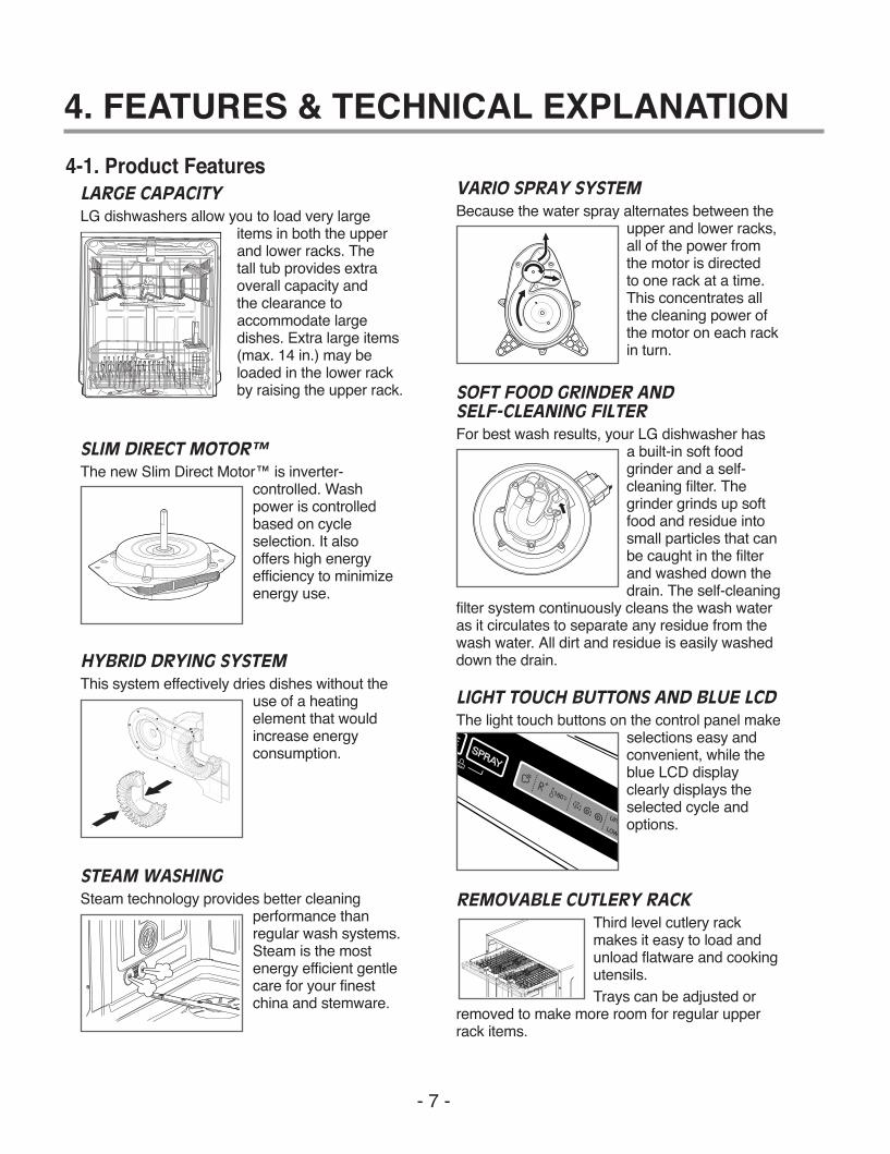
REMOVABLE CUTLERY RACKThird level cutlery rackmakes it easy to load andunload flatware and cookingutensils.Trays can be adjusted or
removed to make more room for regular upperrack items.
4-1. Product FeaturesLARGE CAPACITYLG dishwashers allow you to load very large
items in both the upperand lower racks. The tall tub provides extraoverall capacity and the clearance toaccommodate largedishes. Extra large items(max. 14 in.) may beloaded in the lower rackby raising the upper rack.
SLIM DIRECT MOTOR™The new Slim Direct Motor™ is inverter-
controlled. Washpower is controlledbased on cycleselection. It also offers high energyefficiency to minimizeenergy use.
HYBRID DRYING SYSTEMThis system effectively dries dishes without the
use of a heatingelement that wouldincrease energyconsumption.
VARIO SPRAY SYSTEMBecause the water spray alternates between the
upper and lower racks,all of the power fromthe motor is directed to one rack at a time.This concentrates allthe cleaning power ofthe motor on each rackin turn.
SOFT FOOD GRINDER ANDSELF-CLEANING FILTERFor best wash results, your LG dishwasher has
a built-in soft foodgrinder and a self-cleaning filter. Thegrinder grinds up softfood and residue intosmall particles that canbe caught in the filterand washed down thedrain. The self-cleaning
filter system continuously cleans the wash wateras it circulates to separate any residue from thewash water. All dirt and residue is easily washeddown the drain.
LIGHT TOUCH BUTTONS AND BLUE LCDThe light touch buttons on the control panel make
selections easy andconvenient, while theblue LCD displayclearly displays theselected cycle andoptions.
STEAM WASHINGSteam technology provides better cleaning
performance thanregular wash systems.Steam is the mostenergy efficient gentlecare for your finestchina and stemware.
MFL37554808(S/M) 2009.2.5 8:54 AM ˘���`�7 ‰¯¿ł–�•¡˙¨‰”

- 8 -
4-2. Display Panel LDF 7932 Series
Control panel may vary on some models.
EXTRA RINSE( ), SANITARY( )
1
2
1
2
CYCLESPress the cycle that corresponds to your desired washcycle.
POWER SCRUBThis cycle is for very heavily soiled dishes.
NORMALThis cycle is for normally soiled, everyday loads.
DUAL INTENSITYThis cycle washes the upper and lower racks at differentspray intensities. The default setting for this cycle washesthe lower rack with strong spray intensity and the upperrack with soft spray intensity. This provides optimumcleaning performance for mixed loads, including finechina and stemware. If other combinations are desired,use the steps listed below to change the intensities or touse the HALF LOAD feature.How To Use Dual Intensity1. Press and hold the SPRAY button for three seconds until
the UPPER light begins to blink.2. While the UPPER light is blinking, press the SPRAY
button until the desired intensity for the upper rack isselected.
3. Press the HALF LOAD button to switch to the lower rackand use the SPRAY button to adjust to the desiredintensity.
4. Selections can be cancelled by selecting any cycle except
QUICK WASHThis is a shortened cycle that is perfect for recently usedor lightly soiled loads.
STEAM DELICATEThis cycle adds the gentle power of steam to boost thecleaning power of the delicate cycle. The cycle is perfectfor effectively cleaning delicate items like fine china orstemware.
STEAM FRESHThis cycle can be used to freshen up dishes that mayhave been stored or not used for a long time.
CHIME ON/OFFTo enable or disable the chime, press and hold theQuick Wash and Rinse buttons for 2 seconds.
RINSE ONLYThis cycle is a quick rinse for dishes that will not bewashed immediately. No detergent should be used.To select the Rinse Only cycle, press the Powerbutton; then press the Rinse button once withoutpressing any other cycle buttons.
NOTE: If a main cycle has been selected, the RinseOnly cycle will not be available without first shuttingthe power off.
CANCELTo cancel a running cycle, open the door and thenpress and hold the Dual Intensity and Quick Washbuttons together for 3 seconds. The drain pump will be activated and the cycle will be cancelled.
CYCLE OPTIONS AND DISPLAYPress the desired cycle option buttons to select and set any of the dishwasher’s options describedbelow. The display will show the selected cycle timesand cycle options.
SPRAY (INTENSITY)Repeated pressing of the Spray button will select thedesired spray. The strong, medium, or soft light willshow in the top left portion of the display.
RINSERepeated pressing of the Rinse button will select thedesired Rinse option. The Sanitary, Extra Rinse, orSanitary and Extra Rinse lights will show in thebottom left portion of the display.
3
Soft ( ), Medium ( ), Strong ( )
MFL37554808(S/M) 2009.2.5 8:54 AM ˘���`�8 ‰¯¿ł–�•¡˙¨‰”
- 9 -
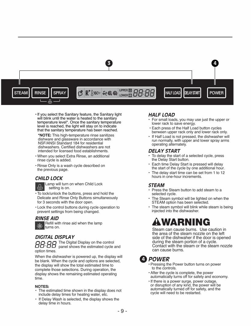
• If you select the Sanitary feature, the Sanitary lightwill blink until the water is heated to the sanitarytemperature level*. Once the sanitary temperaturelevel is reached, the light will stay on to indicatethat the sanitary temperature has been reached.*NOTE: This high-temperature rinse sanitizes dishware and glassware in accordance with NSF/ANSI Standard 184 for residential dishwashers. Certified dishwashers are not intended for licensed food establishments.
• When you select Extra Rinse, an additional rinse cycle is added.
• Rinse Only is a wash cycle described on the previous page.
CHILD LOCKLamp will turn on when Child Lock
setting is on.• To lock/unlock the buttons, press and hold the
Delicate and Rinse Only Buttons simultaneouslyfor 3 seconds with the door open.
• Lock the control buttons during cycle operation toprevent settings from being changed.
RINSE AIDRefill with rinse aid when the lamp turns on.
DIGITAL DISPLAYThe Digital Display on the controlpanel shows the estimated cycle and
option times.When the dishwasher is powered up, the display willbe blank. When the cycle and options are selected,the display will show the total estimated time tocomplete those selections. During operation, thedisplay shows the remaining estimated operatingtime.
NOTES:• The estimated time shown in the display does not
include delay times for heating water, etc.• If Delay Wash is selected, the display shows the
delay time in hours.
HALF LOAD• For small loads, you may use just the upper or
lower rack to save energy.• Each press of the Half Load button cycles
berween upper rack only and lower rack only.• If Half Load is not pressed, the dishwasher will
run normally, with upper and lower spray armsoperating alternately.
DELAY START• To delay the start of a selected cycle, press
the Delay Start button.• Each time Delay Start is pressed will delay
the start of the cycle by one additional hour.• The delay start time can be set from 1 to 12
hours in one-hour increments.
STEAM• Press the Steam button to add steam to a
selected cycle.• The Steam symbol will be lighted on when the
STEAM option has been selected.• The steam symbol will blink while steam is being
injected into the dishwasher.
POWER• Pressing the Power button turns on power
to the controls.• After the cycle is complete, the power
automatically turns off for safety and economy.• If there is a power surge, power outage,
or disruption of any kind, the power will beautomatically turned off for safety, and the cycle will need to be restarted.
3 4
wWARNINGSteam can cause burns. Use caution inthe area of the steam nozzle on the leftside of the dishwaher if the door is openedduring the steam portion of a cycle.Contact with the steam or the steam nozzlecan cause burns.
4
MFL37554808(S/M) 2009.2.5 8:54 AM ˘���`�9 ‰¯¿ł–�•¡˙¨‰”
- 10 -
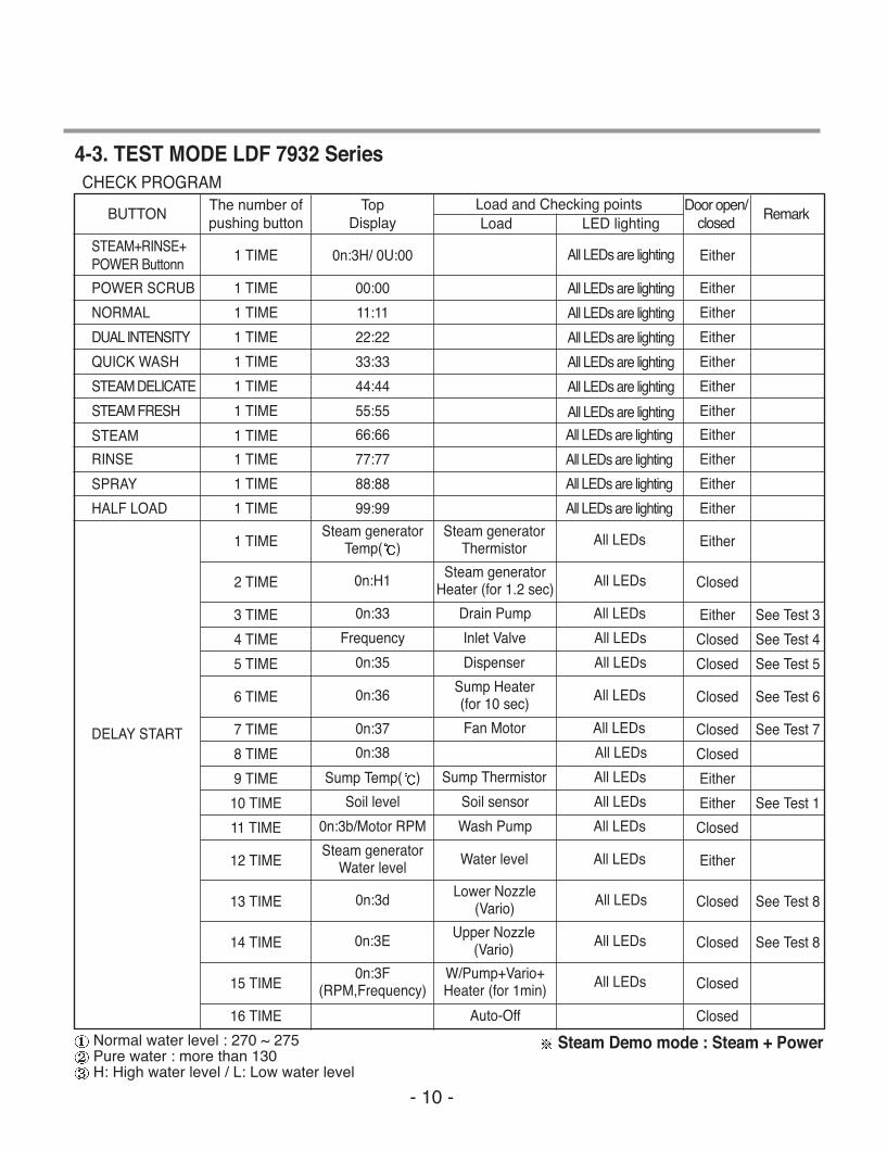
4-3. TEST MODE LDF 7932 SeriesCHECK PROGRAM
BUTTONThe number ofpushing button
TopDisplay LED lightingLoad
Load and Checking points Door open/closed
Remark
STEAM+RINSE+POWER Buttonn
POWER SCRUB
NORMAL
DUAL INTENSITY
QUICK WASH
STEAM DELICATE
STEAM FRESH
STEAM
SPRAY
RINSE
HALF LOAD
DELAY START
Normal water level : 270 ~ 275Pure water : more than 130H: High water level / L: Low water level
1 TIME
1 TIME
1 TIME
1 TIME
1 TIME
1 TIME
1 TIME
1 TIME
1 TIME
1 TIME
1 TIME
1 TIME
2 TIME
3 TIME
4 TIME
5 TIME
6 TIME
7 TIME
8 TIME
9 TIME
10 TIME
11 TIME
12 TIME
13 TIME
14 TIME
15 TIME
16 TIME
Steam generatorTemp( )
0n:H1
0n:33
Frequency
0n:35
0n:36
0n:37
0n:38
Sump Temp( )
Soil level
0n:3b/Motor RPM
Steam generatorWater level
0n:3d
0n:3E
Auto-Off
0n:3F(RPM,Frequency)
0n:3H/ 0U:00
00:00
11:11
22:22
33:33
44:44
55:55
66:66
77:77
88:88
99:99
Steam generatorThermistor
Steam generatorHeater (for 1.2 sec)
Drain Pump
Inlet Valve
Dispenser
Sump Heater(for 10 sec)
Fan Motor
Sump Thermistor
Soil sensor
Wash Pump
Water level
Lower Nozzle(Vario)
Upper Nozzle(Vario)
W/Pump+Vario+Heater (for 1min)
All LEDs
All LEDs
All LEDs
All LEDs
All LEDs
All LEDs
All LEDs
All LEDs
All LEDs
All LEDs
All LEDs
All LEDs
All LEDs
All LEDs
All LEDs
Either
All LEDs are lighting
All LEDs are lighting
All LEDs are lighting
All LEDs are lighting
All LEDs are lighting
All LEDs are lighting
All LEDs are lighting
All LEDs are lighting
All LEDs are lighting
All LEDs are lighting
All LEDs are lighting
Either
Either
Either
Either
Either
Either
Either
Either
Either
Either
Either
Closed
Either
Closed
Closed
Closed
Closed
Closed
Either
Either
Closed
Either
Closed
Closed
Closed
Closed
See Test 3
See Test 4
See Test 5
See Test 6
See Test 7
See Test 1
See Test 8
See Test 8
Steam Demo mode : Steam + Power
MFL37554808(S/M) 2009.2.5 8:54 AM ˘���`�10 ‰¯¿ł–�•¡˙¨‰”

- 11 -
5. PARTS NAME
The appearance and specifications may be varied without notice according to localities.
5-3. LDF 9932 Series
INSTALL BRACKET WOOD SCREW
CONTROL PANEL
DOOR HANDLE
FRONT COVER
LOWER COVER
LEVELING FEET
FRONT DISPLAY (SignaLight™)
BASE
TOP SPRAY ARM
UPPER SPRAY ARM
1
2
4
5
3
6
9
7
8
11
14
15
12
10
STEAM NOZZLE
LOWER SPRAY ARM
DETERGENT AND RINSE AIDDISPENSER
DRYING VENT COVER
TUB LAMP(Illumitub™)
CUTLERY RACK
UPPER RACK
SILVERWARE BASKET
LOWER RACK
TOP DISPLAY
POWER BUTTON
1
2
5
6
3
4
7
8
9
10
11
12
15
16
13
14
17
18
19
20
16
17
18
19
2013
MFL37554808(S/M) 2009.2.5 8:54 AM ˘���`�11 ‰¯¿ł–�•¡˙¨‰”

- 12 -
6. PROGRAM CHART(SCHEMATIC DIAGRAM)LDF 9932 Series
Pro
gram
cha
rt
MFL37554808(S/M) 2009.2.5 8:54 AM ˘���`�12 ‰¯¿ł–�•¡˙¨‰”

- 13 -- 13 -
BEFORE DISASSEMBLING THE DISHWASHER ;1) Remove the cord from electric outlet to avoid electric shock.2) Close the Water Tap (faucet).3) Remove all dishes and items in the dishwasher.4) Remove the Lower Rack and the Upper Rack.5) Remove the inlet hose and drain hose connetion to avoid the hose damages.6) Prepare some towels to avoid floor wet by the water left in the dishwasher.
7. HOW TO DISASSEMBLE
7-1. FULL DISASSEMBLE1. Lower Cover and Lower Felt
1) Remove the front 2 screws.2) Remove the Inlet Hose and Power Supply
Cable.
2. Tub Felt1) Tub Felt
Lower Cover
Tub Felt
MFL37554808(S/M) 2009.2.5 8:54 AM ˘���`�13 ‰¯¿ł–�•¡˙¨‰”

- 14 -- 14 -
Control Panel Front Cover
Controller
Controller
Latch Assembly
3-1. Door Assembly 1) Front Cover
Open the door.
Remove 12 screws(stainless).
2) Control Panel Assembly
Remove 2 screws(Stainless).
Remove the wire connections.Be sure the wiring should not bechanged in reassembling
Remove the Latch assembly.
Remove the Front Display.
Remove 8 screws for Controller.
MFL37554808(S/M) 2009.2.5 8:54 AM ˘���`�14 ‰¯¿ł–�•¡˙¨‰”

- 15 -- 15 -
Fan Assembly
Inner CoverGasket
Flange
Hose
Detergent Dispenser
Door Hinge
Air Duct
Door Bracket
Hinge Bracket
Hinge Spring
3) Fan Assembly
Open the door.
Remove 4 screws and a earth screw forDoor Bracket.
Remove the wire connetions.
Remove the Air Duct.
Turn the Inner Cover counterclockwise.
4) Detergent Dispenser
Close the door
Remove the wire connections.
Remove 6 screws with brackets.
Push the Detergent slowly pulling up thethe Flange by Standard Screwdriver.
5) Door Spring (Right & Left)
Push the Spring upwards and take it offfrom the Hinge Bracket.Be careful not to be injured by thesharpedge of Tub.
Take off the Hinge Link from the Hinge.
6) Door Liner
Open the door.
Pull the Door Liner and take it off fromthe Hinge Supporter.
Door Liner Assembly
Hinge Supporter
MFL37554808(S/M) 2009.2.5 8:54 AM ˘���`�15 ‰¯¿ł–�•¡˙¨‰”

- 16 -- 16 -
Lead Wire Holer Hook
Lead Wire Holer
Lower Frame
Drain Hose
Drain Hose Holder
4. Lower Frame 1) Press the holder hook as shown in figure.2) Remove 4 screws.
6. Drain Hose Holder 1) Press the holder hook as shown in figure.2) Pull the Drain Hose and remove the Drain
Hose Holder.
5. Put the Dishwasher upside down.
MFL37554808(S/M) 2009.2.5 8:54 AM ˘���`�16 ‰¯¿ł–�•¡˙¨‰”

- 17 -- 17 -
7. Base Cover 1) Remove 2 screws.2) Pull the Base Cover out.
8. Harness & Hose Assembly 1) Remove the wiring connections.2) Remove the Hose connections from
Sump Assembly.
You can see the information of WiringDiagram at the back of Lower Cover.
Cabinet Base
Base Cover
MFL37554808(S/M) 2009.2.5 8:54 AM ˘���`�17 ‰¯¿ł–�•¡˙¨‰”
- 18 -- 18 -
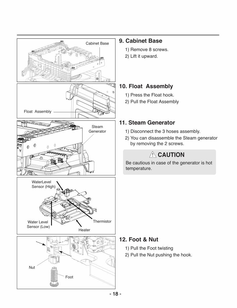
9. Cabinet Base1) Remove 8 screws.2) Lift it upward.
12. Foot & Nut1) Pull the Foot twisting2) Pull the Nut pushing the hook.
Cabinet Base
Float Assembly
WaterLevelSensor (High)
Thermistor
Heater
Water LevelSensor (Low)
10. Float Assembly1) Press the Float hook.2) Pull the Float Assembly
11. Steam Generator1) Disconnect the 3 hoses assembly.2) You can disassemble the Steam generator
by removing the 2 screws.
SteamGenerator
Nut
Foot
CAUTIONBe cautious in case of the generator is hottemperature.
MFL37554808(S/M) 2009.2.5 8:54 AM ˘���`�18 ‰¯¿ł–�•¡˙¨‰”

- 19 -
Inlet ValveCabinet Base
Air BrakerNut
Gasket
Air BrakerAssembly
14. Inlet Valve1) You can disassemble the lnlet Valve by
removing the 2 screws.
13. Rear Leg Adjustment System1) Remove 2 screws.2) Pull the Holder.3) Pull the Leg Adjust.4) Pull the Shaft Assembly.
15. Air Braker Assembly1) Disconnect the 3 hoses assembly.2) Turn the Air Braker Nut counterclockwise.
Be careful the o-ring should not be lost.
Holder
Leg Adjust
Shaft Assembly
MFL37554808(S/M) 2009.2.5 8:54 AM ˘���`�19 ‰¯¿ł–�•¡˙¨‰”

- 20 -- 20 -
Sump Holder
HookSumpAssembly
1) Heater & Drain Motor
Pull the Heater out of the Sump afterreleasing the nut.
Remove 3 screws.
2) Vario Motor
Remove 2 screws for Vario Motor.
Pull the Vario Motor and Micro S/W.
3) Soil Sensor
Pull the Soil Sensor.
16. Sump Assembly
Remove 2 screws.
Remove the Sump Holder and push theSump Assembly down with pulling asideHook.Be careful not to drop the SumpAssembly to the bottom.
Drain Pump
Heater
Vario Motor
MicroS/W
SoilSensor
MFL37554808(S/M) 2009.2.5 8:54 AM ˘���`�20 ‰¯¿ł–�•¡˙¨‰”

- 21 -- 21 -
17. Holder Supporter, Tub Packingand Hinge Supporter Assembly.
When you reassemble the Sump Assembly, becareful not to kink, tear and take off the seals.
You must take off Stopper Roller(F117) by –screwdriver to change the Rail Assembly.(Stopper Roller could be broken while you aretaking off. So you should be careful not to behurt and have extra stopper rollers ready atservicing at all times)
Rotate the screwdriver, after slide it into thegap between Stopper Roller and Rail Roller.
MFL37554808(S/M) 2009.2.5 8:54 AM ˘���`�21 ‰¯¿ł–�•¡˙¨‰”

- 22 -- 22 -
A. TROUBLE SHOOTING ACCORDING TO DISPLAYED ERROR MESSAGE
ERROR MESSAGE POSSIBLE CAUSE REMEDYFOR ERROR OCCURRENCE
The Water Supply Tap is closed.The Water Supply is shut off.The Inlet Hose is kinked.The Water Pressure is very low.(below 10 psi)Inlet Valve is OK?The filter of Inlet Valve is cloggedby impure water.The Hall sensor is OK?The Impeller of Air Guide is bound.
The Drain Hose kinked or blocked.Wiring connection is OK?The drain outlet of sump is blocked.The Drain Pump/Motor or circuit istroubled.
Water leakage in Hose connections.Water is leaked by damages.The Motor Water Seal leakage ofSump assembly.The height of Drain Hose connection(sink-Drain Hose) is not over 20 .Impeller of the Washing Pump is worn away.
Remove the cause of kink or block.Check the wiring connection.Measure the electric resistance ofDrain Motor. (20-40 )Replace the Drain Motor or repairthe Circuit.
Replace the connections of Hose.Check the point of damages andrepair or replace the related parts.Read the Installation Instructions(page 9) and fix it to therecommended Height.Replace the Impeller of theWashing Pump.
Take action on Water Supplydevice.
Measure the electric resistance ofInlet Valve. (950-1300 )Clean the filter of Inlet Valve.Check the frequency of Inlet Waterby the Test Mode.Replace the Air Braker.
Not reached to the nor-mal water level in spiteof 10 min. water supply
INLET ERROR
displayed
Condition
Not fully drained out inspite of 5 min. drainoperation
The excessive RPM ofWashing Motorhappened during Washcycle due to waterleakage.
DRAIN ERROR
displayed
Condition
LEAKAGE ERROR
displayed
Condition
8.TROUBLE SHOOTING METHODS
MFL37554808(S/M) 2009.2.5 8:54 AM ˘���`�22 ‰¯¿ł–�•¡˙¨‰”

- 23 -- 23 -
ERROR MESSAGE POSSIBLE CAUSE REMEDYFOR ERROR OCCURRENCE
The Inlet Valve is troubled.The Controller is troubled.
The Inlet Water Temperature isvery high. (over 194 )Wiring connection is OK?The Thermistor is OK?
Wiring connection is OK?The Impeller of Washing Pump islocked.The rotor of Washing Motor islocked.The Blade is locked.
Check the temperature. (Test Mode)If the temperature is displayed,
adjust the Inlet WaterTemperature to 120 .
If the temperature is notdisplayed,
check the wiring connection.check the electric resistanceof Thermistor. (11~14k at 77 )Replace the PCB.
Replace the Inlet Valve.Repair or replace the Controller.
Excessive water is sup-plied than normal waterlevel.(Automatically drainPump operated.)
EXCESS ERROR
displayed
Condition
The resistance of ther-mistor not normally out put.
THERMAL ERROR
displayed
Condition
Check the wiring connection.Replace the cause of restriction.Replace the Washing Motor.Replace the PCB.
The Motor is workingabnormally.
MOTOR ERROR
displayed
Condition
The Circuit of Heater is troubled.The Thermistor is troubled.The Heater is shorted.The Relay Circuit is troubled.
Repair the Circuit of Heater.Replace the Thermistor.Replace the Heater.Repair the Relay Circuit..
The water is not heated orthe temperature in the Tubis overheated to over 194ßF
HEATER ERROR
displayed
Condition
MFL37554808(S/M) 2009.2.5 8:54 AM ˘���`�23 ‰¯¿ł–�•¡˙¨‰”

- 24 -
B. STEAM GENERATOR ERROR MESSAGE
The normal condition
The generator heater temperatureis high. (over 239 )
The water leveling sensor is workingabnormally.
Not reached to the normal waterlevel.
The generator heater temperatureis low. (lower than 158 )
The normal condition
Check the water level sensor andthermistor check.
Check the wiring connection andwater level sensor.
Check the inlet valve and sensorconnection.
Check the heater and thermistor.
00 : E0
00 : E1
00 : E2
00 : E3
00 : E4
00 : E5
ERROR MESSAGE CONDITION REMEDY
Steam Generator Error mode is not displayed in normal condition and it can be confirmedby following additional operation.To confirm steam generator error, press the DELAY START and RINSE ONLY buttonssimultaneously.When Steam Generator is out of order, dishwasher operates the selected cycle withoutsteam.
MFL37554808(S/M) 2009.2.5 8:54 AM ˘���`�24 ‰¯¿ł–�•¡˙¨‰”

- 25 -- 25 -
No Power on when the power button pressed.
The Power connectionis correctly connected.
The Fuse or Circuit Breaker of house is O.K?
The Power Switch or
the Circuit is O.K?
• Re-connect the Powr connection.
• Check the electricity is failed or not.
• Replace the Fuse or Circuit Breaker of house.
• Check the Power Switch or the circuit and repair it.
Check t he Con t ro l l e r. (Powe r C i r cu i t )
C. TROUBLE DIAGNOSES AND REPAIR BY SYMPTOM
NO
NO
YES
YES
YES
NO
MFL37554808(S/M) 2009.2.5 8:54 AM ˘���`�25 ‰¯¿ł–�•¡˙¨‰”

- 26 -- 26 -
The Wash Pump/Motor does not run.
The Door is tightly closed?
The Wiring connectionsis OK?
The Blade is not locked by a small and sharp object?
• close the Door tightly.
• Check the Door Switch in Latch Handle.
• Re-connect the wiring connections related to the
Washing Motor.
• Remove the cause of lock or replace the Blade.
Replace the Wahing Pump/Motor
NO
NO
NO
YES
YES
YES
MFL37554808(S/M) 2009.2.5 8:54 AM ˘���`�26 ‰¯¿ł–�•¡˙¨‰”

- 27 -- 27 -
Washing Results are not Satisfactory
After washing, are there still White deposits or streaks onthe dishes?
NO
After washing, are there still
food soils on the dishes?
YES
Check that : - the amount of detergent Correctly used or not- Filters clogged or not.- the holes of spray arms blocked or not.- Utensils are correctly arranged or not.- Utensils are overloaded or not.- the spray arm rotating is obstructed or not.- the program is correctly selected or not.
Reduce the amount of Rinse-Aid(for Streak)
YES
Dry Results are not satisfactory
Increase the amount of Rinse-Aid.(Set the number higher)
Select the Program that the Rinse temperature is higher.
MFL37554808(S/M) 2009.2.5 8:54 AM ˘���`�27 ‰¯¿ł–�•¡˙¨‰”

- 28 -- 28 -
Power Button not automatically off after operation.
Check the button is blocked by foreign materials.
Check the Power Switch.(Replace it, if necessary.)
Check the Controller.(Replace it, if necessary.)
MFL37554808(S/M) 2009.2.5 8:54 AM ˘���`�28 ‰¯¿ł–�•¡˙¨‰”

- 29 -- 29 -
9. INSTALLATION INSTRUCTION
Step 1: PREPARE CUPBOARD OPENING
1. This dishwasher is designed to fit a standard dishwasher opening as shown below.
2. Select a location as close to sink as possible for easy connections to water and drain lines.
3. The dishwasher should not be installed more than 10 ft. (3m) from the sink for properdrainage.
4. If dishwasher is to be installed in a corner, a minimum of 2 in. (50mm) is required betweenthe dishwasher and an adjacent a wall.
Ensure the floor under the dishwasher is at the same level as the rest of the room to
allow for any service requirements.
33 1
/2″(
851m
m)m
in.
If dishwasher will sit directly onsubflooring, subfloor should besealed with a waterproof paint orsealer to prevent damage fromsteam.
Drill a 1-1/2 (38mm) dia hole or cutout for drain hose, inlet hose andelectrical cables on either side.
approx. 4 (100mm, W) X 4 (100mm, H)
These openings must be within 4(100mm) from the floor and 1-5/8(40mm) from the back wall. If there isa floor in the cabinet under the sink,it will also be necessary to drill or cutthrough the floor to connect thewater and drain under the sink.
MFL37554808(S/M) 2009.2.5 8:54 AM ˘���`�29 ‰¯¿ł–�•¡˙¨‰”
- 30 -- 30 -
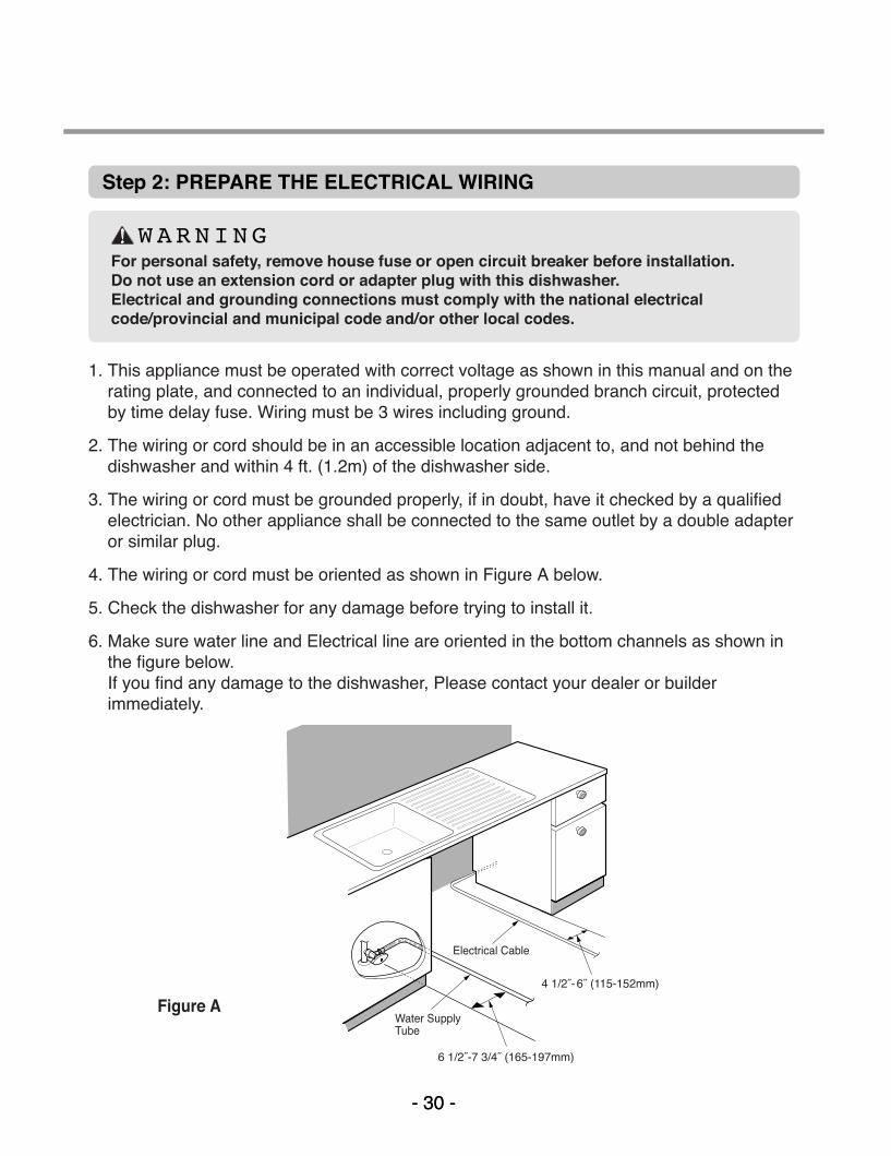
WARNINGFor personal safety, remove house fuse or open circuit breaker before installation. Do not use an extension cord or adapter plug with this dishwasher.Electrical and grounding connections must comply with the national electricalcode/provincial and municipal code and/or other local codes.
Figure A
Step 2: PREPARE THE ELECTRICAL WIRING
1. This appliance must be operated with correct voltage as shown in this manual and on therating plate, and connected to an individual, properly grounded branch circuit, protectedby time delay fuse. Wiring must be 3 wires including ground.
2. The wiring or cord should be in an accessible location adjacent to, and not behind thedishwasher and within 4 ft. (1.2m) of the dishwasher side.
3. The wiring or cord must be grounded properly, if in doubt, have it checked by a qualifiedelectrician. No other appliance shall be connected to the same outlet by a double adapteror similar plug.
4. The wiring or cord must be oriented as shown in Figure A below.
5. Check the dishwasher for any damage before trying to install it.
6. Make sure water line and Electrical line are oriented in the bottom channels as shown inthe figure below.If you find any damage to the dishwasher, Please contact your dealer or builderimmediately.
MFL37554808(S/M) 2009.2.5 8:54 AM ˘���`�30 ‰¯¿ł–�•¡˙¨‰”

- 31 -- 31 -
Step 3: PREPARE THE WATER SUPPLY CONNECTION
1. This dishwasher may be connected to either hot or cold water. If the water can not bemaintained below 149 (65 ), the dishwasher must be connected to cold water.
2. When connecting the dishwasher water line, sealing tape or compound should be used toavoid leaks.
3. When connecting the dishwasher water line, the house supply should be shut off.
4. The Water Supply Tube must be oriented as shown in Figure A on page 6.
Step 4: PREPARE DISHWASHER FOR INSTALLATION
1. Adjust the legs to the required height to fit properly under the countertop as shown below.
2. Check the level of dishwasher by using level.
Left side – turn theadjusting screwcounterclockwise to lowerthe leg and raise the rearof the dishwasher.
Right side – turn theadjusting screw clockwiseto lower the leg and raisethe rear of the dishwasher.
Front feet can be adjustedfrom the top using a 1/4square drive wrench.
MFL37554808(S/M) 2009.2.5 8:54 AM ˘���`�31 ‰¯¿ł–�•¡˙¨‰”

- 32 -- 32 -
1. Remove the Lower Cover and orient dishwasher as shown below.
2. Before sliding the dishwasher into the cupboard opening, make all necessary heightadjustments using the legs.
3. Slide the dishwasher into the cabinet opening carefully. Make sure that the drain hoseinside the cabinet is not kinked.
4. Follow the instruction as in Figure B.
Step 5: INSTALL THE DISHWASHER IN CUPBOARD
MFL37554808(S/M) 2009.2.5 8:54 AM ˘���`�32 ‰¯¿ł–�•¡˙¨‰”
- 33 -- 33 -
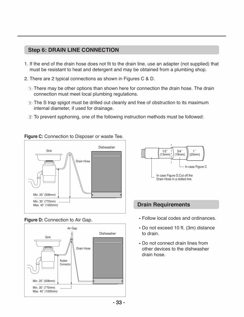
Step 6: DRAIN LINE CONNECTION
1. If the end of the drain hose does not fit to the drain line, use an adapter (not supplied) thatmust be resistant to heat and detergent and may be obtained from a plumbing shop.
2. There are 2 typical connections as shown in Figures C & D.
There may be other options than shown here for connection the drain hose. The drainconnection must meet local plumbing regulations.
The S trap spigot must be drilled out cleanly and free of obstruction to its maximuminternal diameter, if used for drainage.
To prevent syphoning, one of the following instruction methods must be followed:
Follow local codes and ordinances.
Do not exceed 10 ft. (3m) distanceto drain.
Do not connect drain lines fromother devices to the dishwasherdrain hose.
Drain Requirements
Figure C: Connection to Disposer or waste Tee.
Figure D: Connection to Air Gap.
MFL37554808(S/M) 2009.2.5 8:54 AM ˘���`�33 ‰¯¿ł–�•¡˙¨‰”

- 34 -- 34 -
Step 7: WATER SUPPLY CONNECTION
1. When connecting, sealing tape orsealing compound should beused to avoid water leaks.
2. Before connecting, turn off the watersupply.
3. After fitting the Elbow into theInlet Valve, slide the FlexibleStainless Tube or Copper Tubeinto the Elbow.
4. Tighten the nut and make surethat the line is not kinked orsharply bent.
Inlet Valve
Water Supply Tube
Elbow
1. Before beginning, turn off electricalpower to the unit at the circuit breaker.
2. Remove the Junction Cover and thenInstall the Strain Relief.
3. Twist Wire Connectors tightly on thewires. Wrap each connection withElectrical tape.
4. Check again and make sure that allwires are connected correctly, black toblack, white to white, green to green(ground to ground).
5. Replace the Junction Cover.
Junction Box
Junction Cover
Step 8: ELECTRICAL POWER CONNECTION
MFL37554808(S/M) 2009.2.5 8:54 AM ˘���`�34 ‰¯¿ł–�•¡˙¨‰”
- 35 -- 35 -
Step 9: FINAL CHECKS
1. Turn electrical power back on at the circuit breaker.
2. Turn house water supply back on.
3. Operate the dishwasher through one cycle (Quick cycle is recommended) to check forwater leaks and operating conditions.
4. Replace the Lower Cover.
MFL37554808(S/M) 2009.2.5 8:54 AM ˘���`�35 ‰¯¿ł–�•¡˙¨‰”
- 36 -- 36 -
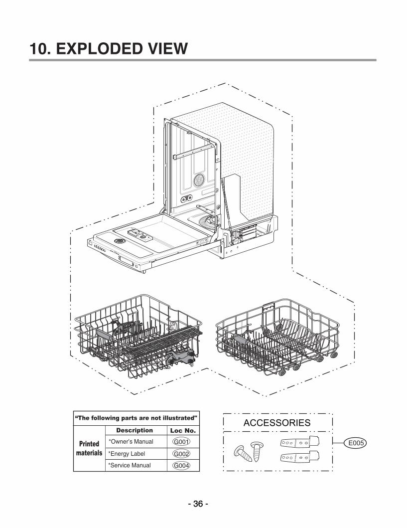
Printedmaterials
Description
*Owner’s Manual
*Energy Label
Loc No.
*Service Manual
G001
G002
G004
“The following parts are not illustrated" ACCESSORIES
E005
10. EXPLODED VIEW
MFL37554808(S/M) 2009.2.5 8:54 AM ˘���`�36 ‰¯¿ł–�•¡˙¨‰”
- 37 -- 37 -
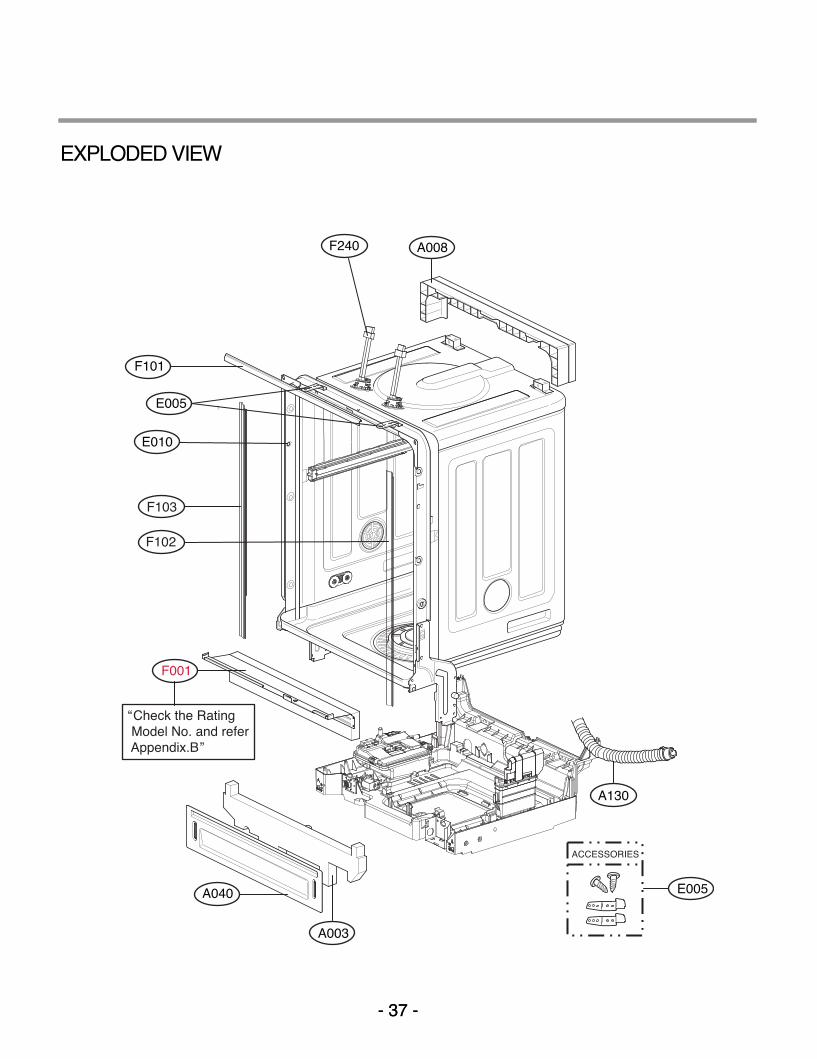
F102
F103
A008
F101
E005
E010
A040
A003
A130
ACCESSORIES
E005
F001
“Check the Rating Model No. and refer Appendix.B”
F240
EXPLODED VIEW
MFL37554808(S/M) 2009.2.5 8:54 AM ˘���`�37 ‰¯¿ł–�•¡˙¨‰”

- 38 -
F011
F013M006
M005
F011
F013
F040
F060
F050
F022F230
F300
F042F041
F144
F132
F143
F171
F122
F123
F121
UPPER RACK RAIL - LEFT
F121 F122
F123
UPPER RACK RAIL - RIGHT
F110
F113
F112
F113
F210
F111F117
F111
F118
F117
EXPLODED VIEW - TUB ASSEMBLY
MFL37554808(S/M) 2009.2.5 8:54 AM ˘���`�38 ‰¯¿ł–�•¡˙¨‰”

- 39 -- 39 -
A050F191
F192
F004
F005
A070
A060
A074
A073
M260
A160
M090
F043
F045
M086
M500
M100
M210
M266
M105
M261
EXPLODED VIEW - BASE ASSEMBLY
EXPLODED VIEW - NOZZLE ASSEMBLY
M100 Serial No.:810KW***~
MFL37554808(S/M) 2009.2.5 8:54 AM ˘���`�39 ‰¯¿ł–�•¡˙¨‰”
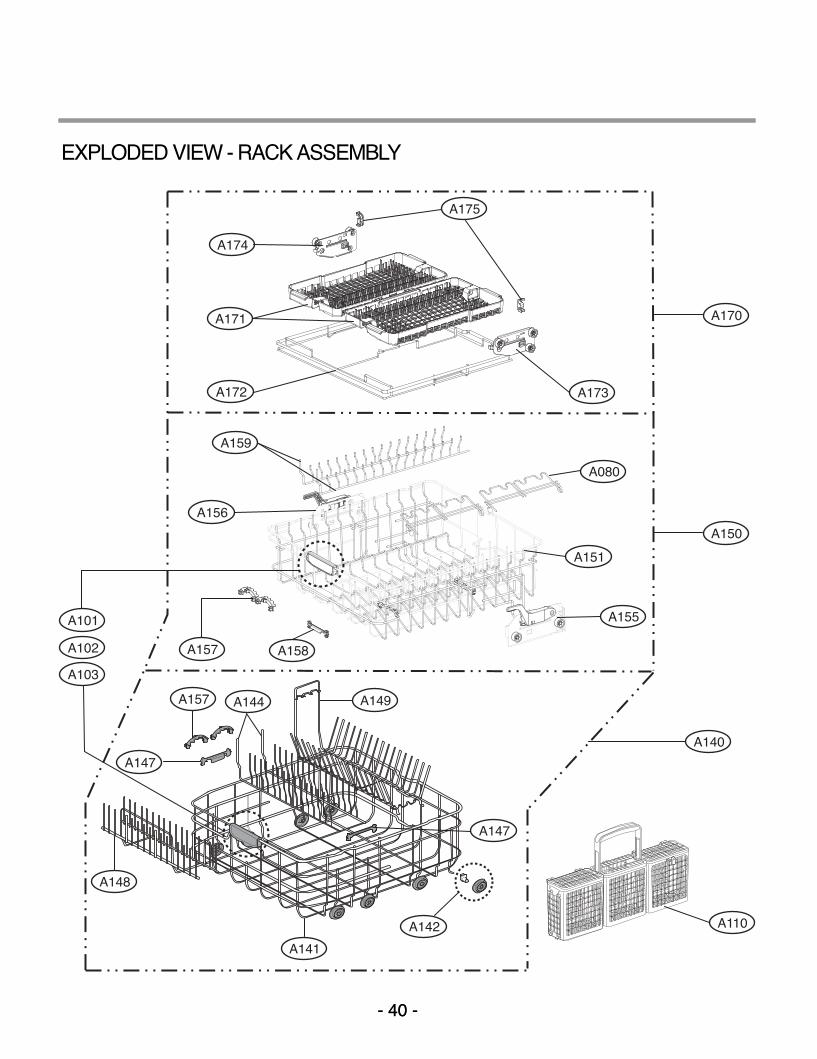
- 40 -- 40 -
A158
A140
A157
A151
A110
A101
A102
A103
A156
A159
A155
A172
A171
A173
A174
A175
A080
A150
A170
A147
A157 A149A144
A148
A141
A142
A147
EXPLODED VIEW - RACK ASSEMBLY
MFL37554808(S/M) 2009.2.5 8:54 AM ˘���`�40 ‰¯¿ł–�•¡˙¨‰”

- 41 -- 41 -
K200
K220
K253
K260K207
K215K207
K252
K251
“Check the Rating Model No. and refer Appendix.B”
K254
EXPLODED VIEW - PANEL ASSEMBLY
MFL37554808(S/M) 2009.2.5 8:54 AM ˘���`�41 ‰¯¿ł–�•¡˙¨‰”
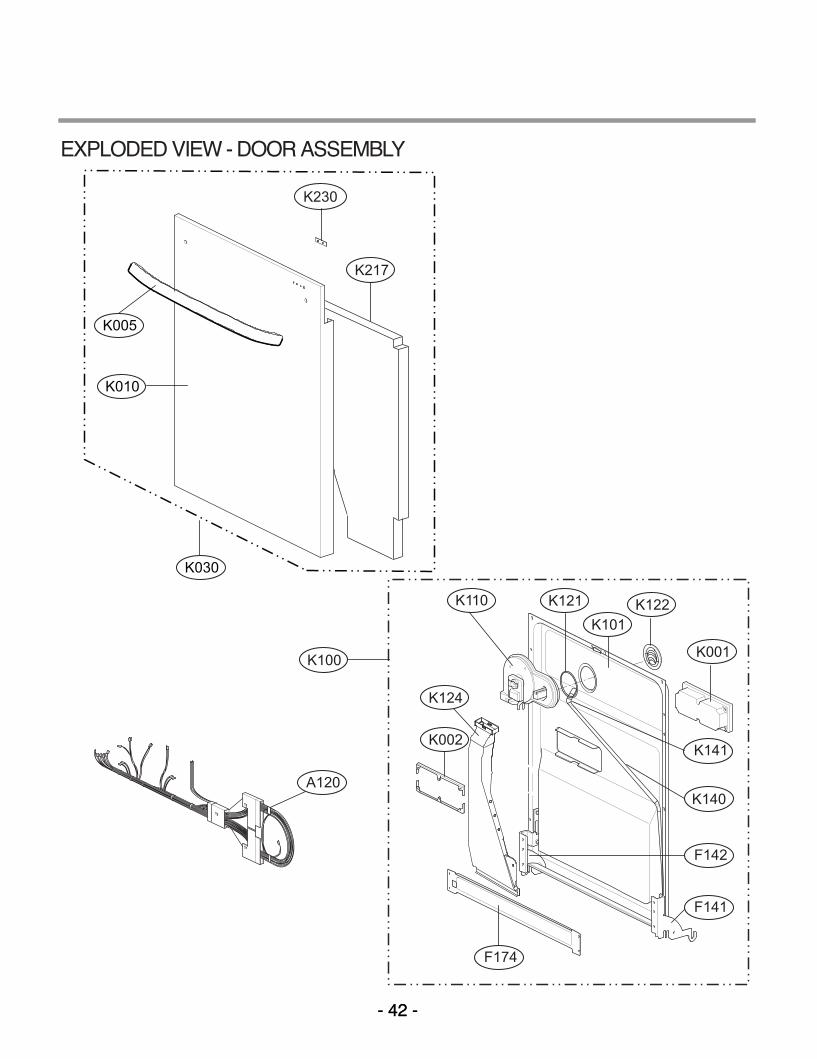
- 42 -- 42 -
K217
K030
K010
K005
K230
K002
A120
K001
K122K110 K121K101
F174
F142
F141
K124
K140
K100
K141
EXPLODED VIEW - DOOR ASSEMBLY
MFL37554808(S/M) 2009.2.5 8:54 AM ˘���`�42 ‰¯¿ł–�•¡˙¨‰”

- 43 -
M001
M110
M038
M025
M035
M130
M036
M007
M087
M060
M081
M120
M034M088
M027
M028
M026
M050
M031
M220
EXPLODED VIEW - SUMP ASSEMBLY
MFL37554808(S/M) 2009.2.5 8:54 AM ˘���`�43 ‰¯¿ł–�•¡˙¨‰”

P/No. : MFL37554808
MFL37554808(S/M) 2009.2.5 8:54 AM ˘���`�1 ‰¯¿ł–�•¡˙¨‰”