Embed Size (px)
Citation preview
May 2015 www.ies.org
The magazine of the Illuminating Engineering Society of North America
Off ice 2.0 Beats By Dre
McCann Erickson
Jacobs Engineering
ShopperTrak
LDA May cover VI b+.indd 2LDA May cover VI b+.indd 2 3/4/15 4:35 PM3/4/15 4:35 PM
RESEARCH
86 LD+A May 2015 www.ies.org
Due to the increased availability and cost-eff ectiveness of LED multi-
faceted reflector (MR) lamps, residential and commercial users are
looking to these products for an energy-eff icient alternative to tra-
ditional, halogen MR sources. While the energy savings associated
with this switch are easy to see, actual product performance may be less clear-
cut. Consumers have experienced performance issues including visible flicker
and audible humming, which have been linked to the use of the LED lamps
with certain types of electrical components including some types of dimmer
switches and low-voltage transformers.
To help better understand the current state of the LED MR market and associ-
ated performance issues, researchers in California evaluated a cross-section of
commercially available LED MR16 lamps, the most common type of MR lamp,
to better understand the product’s compatibility with electrical components
designed for use with traditional halogen sources. Researchers at the California
Lighting Technology Center (CLTC) at UC Davis conducted performance evalua-
tions of 20 commercially available LED MR16 lamps operated in conjunction with
multiple types of low-voltage transformers, LED drivers and dimmer switches.
The primary study objective was to identify links between poor lamp perfor-
mance, specific LED driver designs and other standard electrical components.
Flicker and noise issues associated with LED MR16 lamps oft en occur because
the LED products draw less current than the halogen MR16s they are designed
to replace. Most existing electronic transformers and dimmer switches are
designed to operate with a halogen lamps’ larger linear load. LED lamps are a
smaller, non-linear load. They use switched mode power supplies (SMPS) in their
drivers to transform DC-DC voltage levels aft er rectification. Simple SMPS imple-
mentations oft en do not draw enough current to reliably turn on the transformer
or dimmer sub-components, nor do they continue to draw enough current con-
sistently for these components to appear continuously ON. This results in varia-
tion of the LED ON-time from cycle to cycle and it’s this variation in light level at
low enough frequencies that can be perceived as visible light flicker.
STUDY DESIGNCLTC selected 20 commercially available, LED MR16 products for testing along
with three diff erent low-voltage transformers and two types of phase-cut dimmer
switches. Testing focused on 12V, LED MR16 lamps with GU5.3 bases. Five samples
of each product were used for deconstruction, an activity conducted to identify
and catalogue the type of driver topology utilized by each product. Manufacturers
typically employ a buck, boost or buck-boost SMPS topology in their drivers in
order to try and avoid the types of per-
formance issues previously described.
Researchers sought to understand
if driver topology had any eff ect on
overall lamp and system performance.
In addition to testing LED MR16 lamp
performance with these various sys-
tem components, researchers also
tested lamp performance with respect
to dimming level and the number of
lamps installed on the circuit.
Each of the 20 products were test-
ed with all possible combinations of
components and operating condi-
tions: transformer type, dimmer type
(including no dimmer), dimming level
and lamp number (Table 1), resulting
in a performance data set of 600 dif-
ferent test scenarios.
One lamp per product was decon-
structed to identify its driver topology
by removing the components around
the circuit boards to reveal the top
code of the driver integrated circuit
(IC). This allowed for determination of
the LED driver IC model and manufac-
turer, which lead to driver datasheets
that included information on the
driver’s electrical topology. CLTC staff
contacted manufacturers for details
of their lamp’s design where decon-
struction activities failed to reveal the
specific LED driver used.
LED MR16 system performance was
first quantified according to the sys-
tem’s overall electrical eff iciency and
the eff iciency of each of the individual
system components. Electrical eff i-
Electrical Compatibility of MR16 LED ReplacementsBy Daniel Stuart and Cori Jackson
86_Research_5.15_r1.indd 8686_Research_5.15_r1.indd 86 3/9/15 4:31 PM3/9/15 4:31 PM
www.ies.org May 2015 LD+A 87
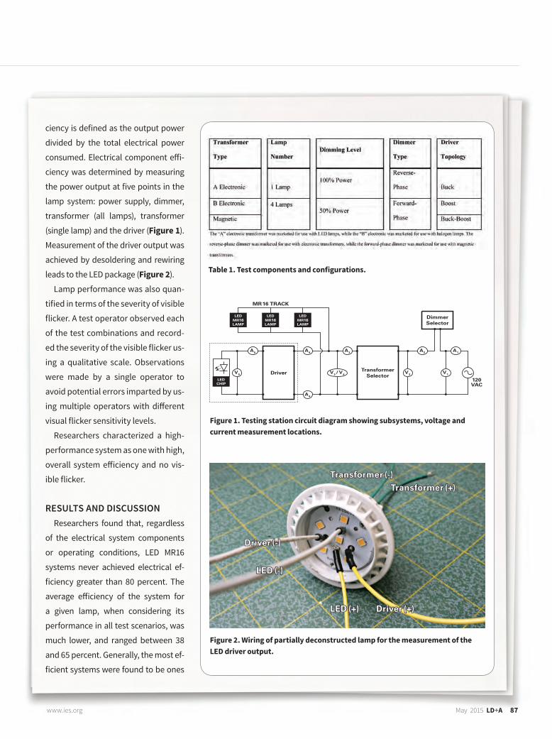
ciency is defined as the output power
divided by the total electrical power
consumed. Electrical component eff i-
ciency was determined by measuring
the power output at five points in the
lamp system: power supply, dimmer,
transformer (all lamps), transformer
(single lamp) and the driver (Figure 1).
Measurement of the driver output was
achieved by desoldering and rewiring
leads to the LED package (Figure 2).
Lamp performance was also quan-
tified in terms of the severity of visible
flicker. A test operator observed each
of the test combinations and record-
ed the severity of the visible flicker us-
ing a qualitative scale. Observations
were made by a single operator to
avoid potential errors imparted by us-
ing multiple operators with diff erent
visual flicker sensitivity levels.
Researchers characterized a high-
performance system as one with high,
overall system eff iciency and no vis-
ible flicker.
RESULTS AND DISCUSSIONResearchers found that, regardless
of the electrical system components
or operating conditions, LED MR16
systems never achieved electrical ef-
ficiency greater than 80 percent. The
average eff iciency of the system for
a given lamp, when considering its
performance in all test scenarios, was
much lower, and ranged between 38
and 65 percent. Generally, the most ef-
ficient systems were found to be ones
Figure 1. Testing station circuit diagram showing subsystems, voltage and current measurement locations.
Figure 2. Wiring of partially deconstructed lamp for the measurement of the LED driver output.
Table 1. Test components and configurations.
86_Research_5.15.indd 8786_Research_5.15.indd 87 3/4/15 4:02 PM3/4/15 4:02 PM
88 January 2015 | LD+A www.ies.org
RESEARCH
88 LD+A May 2015 www.ies.org
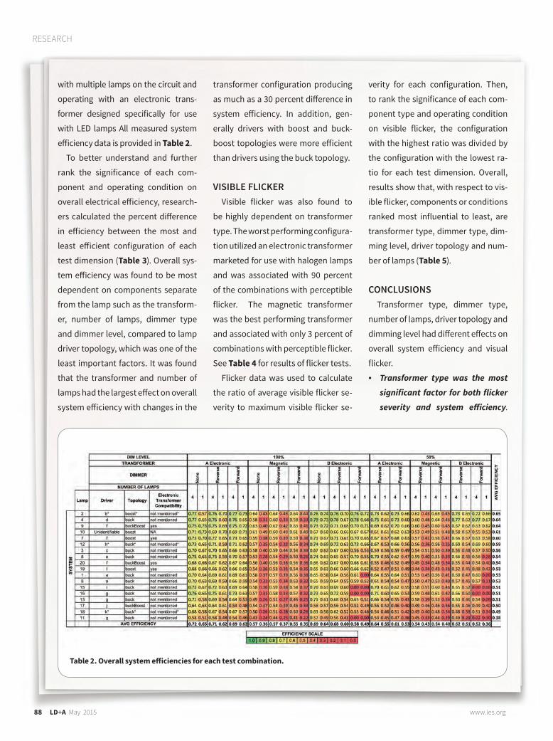
with multiple lamps on the circuit and
operating with an electronic trans-
former designed specifically for use
with LED lamps All measured system
eff iciency data is provided in Table 2.
To better understand and further
rank the significance of each com-
ponent and operating condition on
overall electrical eff iciency, research-
ers calculated the percent diff erence
in eff iciency between the most and
least eff icient configuration of each
test dimension (Table 3). Overall sys-
tem eff iciency was found to be most
dependent on components separate
from the lamp such as the transform-
er, number of lamps, dimmer type
and dimmer level, compared to lamp
driver topology, which was one of the
least important factors. It was found
that the transformer and number of
lamps had the largest eff ect on overall
system eff iciency with changes in the
transformer configuration producing
as much as a 30 percent diff erence in
system eff iciency. In addition, gen-
erally drivers with boost and buck-
boost topologies were more eff icient
than drivers using the buck topology.
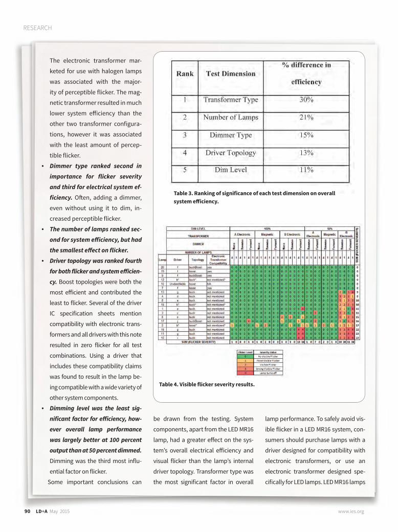
VISIBLE FLICKERVisible flicker was also found to
be highly dependent on transformer
type. The worst performing configura-
tion utilized an electronic transformer
marketed for use with halogen lamps
and was associated with 90 percent
of the combinations with perceptible
flicker. The magnetic transformer
was the best performing transformer
and associated with only 3 percent of
combinations with perceptible flicker.
See Table 4 for results of flicker tests.
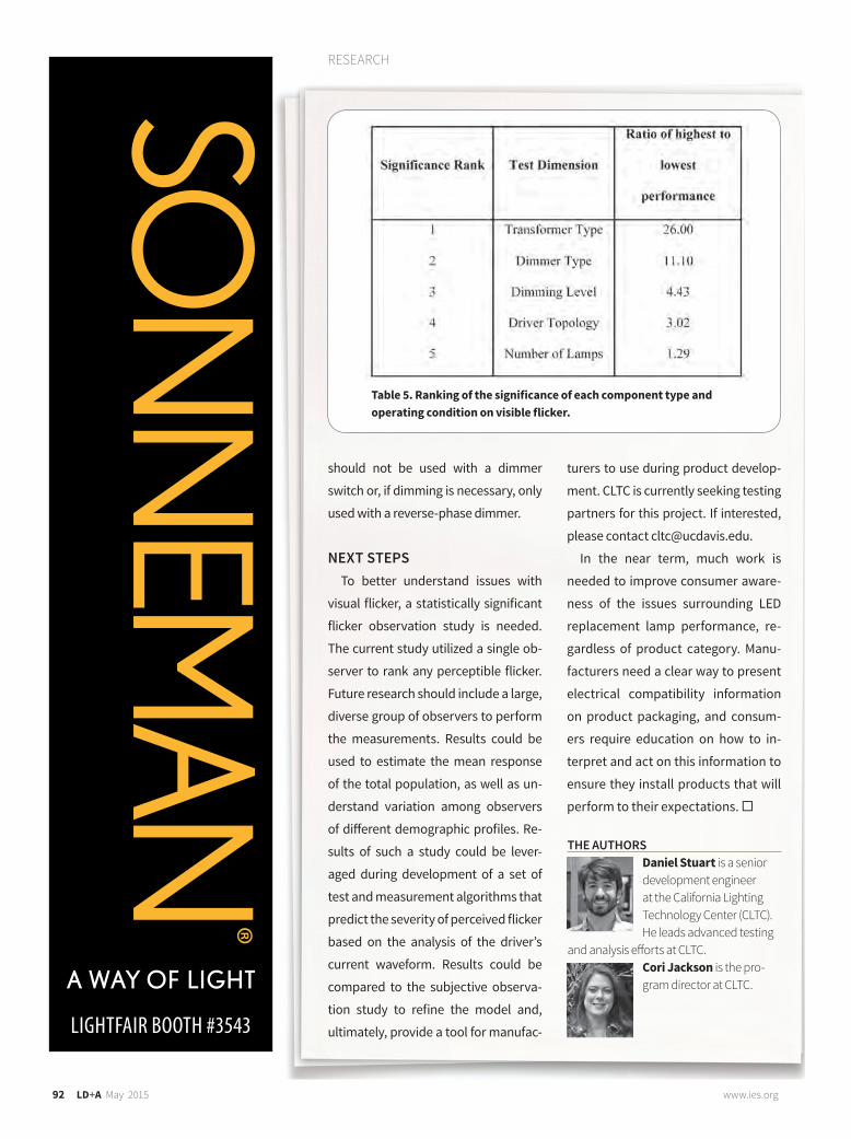
Flicker data was used to calculate
the ratio of average visible flicker se-
verity to maximum visible flicker se-
verity for each configuration. Then,
to rank the significance of each com-
ponent type and operating condition
on visible flicker, the configuration
with the highest ratio was divided by
the configuration with the lowest ra-
tio for each test dimension. Overall,
results show that, with respect to vis-
ible flicker, components or conditions
ranked most influential to least, are
transformer type, dimmer type, dim-
ming level, driver topology and num-
ber of lamps (Table 5).
CONCLUSIONSTransformer type, dimmer type,
number of lamps, driver topology and
dimming level had diff erent eff ects on
overall system eff iciency and visual
flicker.
• Transformer type was the most
significant factor for both flicker
severity and system eff iciency.
Table 2. Overall system eff iciencies for each test combination.
86_Research_5.15.indd 8886_Research_5.15.indd 88 3/4/15 4:03 PM3/4/15 4:03 PM
90 January 2015 | LD+A www.ies.org
RESEARCH
90 LD+A May 2015 www.ies.org
The electronic transformer mar-
keted for use with halogen lamps
was associated with the major-
ity of perceptible flicker. The mag-
netic transformer resulted in much
lower system eff iciency than the
other two transformer configura-
tions, however it was associated
with the least amount of percep-
tible flicker.
• Dimmer type ranked second in
importance for flicker severity
and third for electrical system ef-
ficiency. Oft en, adding a dimmer,
even without using it to dim, in-
creased perceptible flicker.
• The number of lamps ranked sec-
ond for system eff iciency, but had
the smallest eff ect on flicker.
• Driver topology was ranked fourth
for both flicker and system eff icien-
cy. Boost topologies were both the
most eff icient and contributed the
least to flicker. Several of the driver
IC specification sheets mention
compatibility with electronic trans-
formers and all drivers with this note
resulted in zero flicker for all test
combinations. Using a driver that
includes these compatibility claims
was found to result in the lamp be-
ing compatible with a wide variety of
other system components.
• Dimming level was the least sig-
nificant factor for eff iciency, how-
ever overall lamp performance
was largely better at 100 percent
output than at 50 percent dimmed.
Dimming was the third most influ-
ential factor on flicker.
Some important conclusions can
Table 3. Ranking of significance of each test dimension on overall system eff iciency.
Table 4. Visible flicker severity results.
be drawn from the testing. System
components, apart from the LED MR16
lamp, had a greater eff ect on the sys-
tem’s overall electrical eff iciency and
visual flicker than the lamp’s internal
driver topology. Transformer type was
the most significant factor in overall
lamp performance. To safely avoid vis-
ible flicker in a LED MR16 system, con-
sumers should purchase lamps with a
driver designed for compatibility with
electronic transformers, or use an
electronic transformer designed spe-
cifically for LED lamps. LED MR16 lamps
86_Research_5.15.indd 9086_Research_5.15.indd 90 3/4/15 4:03 PM3/4/15 4:03 PM
RESEARCH
92 LD+A May 2015 www.ies.org
should not be used with a dimmer
switch or, if dimming is necessary, only
used with a reverse-phase dimmer.
NEXT STEPSTo better understand issues with
visual flicker, a statistically significant
flicker observation study is needed.
The current study utilized a single ob-
server to rank any perceptible flicker.
Future research should include a large,
diverse group of observers to perform
the measurements. Results could be
used to estimate the mean response
of the total population, as well as un-
derstand variation among observers
of diff erent demographic profiles. Re-
sults of such a study could be lever-
aged during development of a set of
test and measurement algorithms that
predict the severity of perceived flicker
based on the analysis of the driver’s
current waveform. Results could be
compared to the subjective observa-
tion study to refine the model and,
ultimately, provide a tool for manufac-
turers to use during product develop-
ment. CLTC is currently seeking testing
partners for this project. If interested,
please contact [email protected].
In the near term, much work is
needed to improve consumer aware-
ness of the issues surrounding LED
replacement lamp performance, re-
gardless of product category. Manu-
facturers need a clear way to present
electrical compatibility information
on product packaging, and consum-
ers require education on how to in-
terpret and act on this information to
ensure they install products that will
perform to their expectations.
Daniel Stuart is a senior development engineer at the California Lighting Technology Center (CLTC). He leads advanced testing
and analysis eff orts at CLTC.Cori Jackson is the pro-gram director at CLTC.
THE AUTHORS
Table 5. Ranking of the significance of each component type and operating condition on visible flicker.
LIGHTFAIR BOOTH #3543
86_Research_5.15_r1.indd 9286_Research_5.15_r1.indd 92 3/9/15 4:31 PM3/9/15 4:31 PM