Embed Size (px)
Citation preview

Nuclear
nu Program Office Attn: Dr. B. J. Snyder
Program Director US Nuclear Regulatory Commission Washington, DC 20555
Dear Dr. Snyder:
GPU Nuclear Corpor•Uon Post Olf1Ce Box 480 Route 441 South Middletown. Penns�van1a 17057·0191 717 944·7621 TELEX 84·2386 W11ter's 011ect 01al Number: ( 717) 948-8461
441Q-84-L-Ol88 Oocunent lD Ol05A
October 30, .1984
Three Mile Island t+.Jclear Station, lAlit 2 (TMI-2) Operating License No. DPR-73
Docket No. 50-320 General Project Design Criteria
Attached for your information is Revision 5 to the General Project Design Criteria. This revision modifies the definitions for Safety Related and Important to Safety such that they correspond exactly to the nu-2 Recovery Quality Assurance Plan.
If you have any questions concerning this information, please call Mr. J. J. Byrne or my starr.
FRS/JJB/jep
Attac:Nnent
Sincerely,
��f,;;A-Vice P-resident/Director, TMI-2
cc: Deputy Program Director - TMl Program Office, Dr. w. D. Trctvers
8411050397 841030 PDR ADDCK 0�000320 p PDR
GPU Nuclear Corporation IS a subs1d1ary of the General Pubhc Uhhhes Corporation

I ,
'It} · Design Criteria 13587-2-LOl-100
r .
(
.
• .c
GPU SERVICE CORPORATION
THREE MILE IS�AND • UNIT 2
RECOVERY FACILITIE$
DESIGN CRITERIA DOCUMENTS COVER SHEET
( JOB NO: __ --:.;13�58=7 __ _ DISCIPLINE: __ G..;;_en...:.e.;....;ra._l-=S...:;. ec:....;t;,.:.. i o:.;.; n ____ _
� ;5 11�o/� Revised as Noted and Issued for Use 7PdJ; &-s � I) a1 1 14,: c � zr-;1 4 flf/83 Revised as Noted and Issued for Use /r. • I 1 V7 ..J 1/()JJ �� IJ 3 11'/,lez Revised as Noted and Issued for Use
: [ �H Es{f 1 � � 2 �,L Revised as Noted and Issued for Use I 'c:;N c� · /),_,/ ! �--�7������ U�pln�n�G,P�U� N�A�pp r�ov�a�l�����-------+l��v�� 7�-�--�J� ���-+-------rl
.ti. 'llztl Rev1sed as Noted and Issued for Use c:-- ,��:.;_:;.· l'/.h.1/ • -�'�� · ,p 'If' '/� /�1 Upon GPUSC Approval c..-� ,!����� 1/:MQ 1L-:i.. 'fro"'-� "111!.,.. I MJ'. I., � ll . ' .-Z::..7l �:... i;� 0 7&, Issued for Use Upon GPUSC Approval l.r.S INNK IPAJJ 1-J.. LJ � IIEV. QROUI' I'RO.IfCT ;!, DATI R£VISIOII DESCRiniOM ORIGIUTO" SUI'V. fNG. � MO. 8411050400 841030 APPROVAL
PDR ADOCK 05000320 P PDR
GPUSC
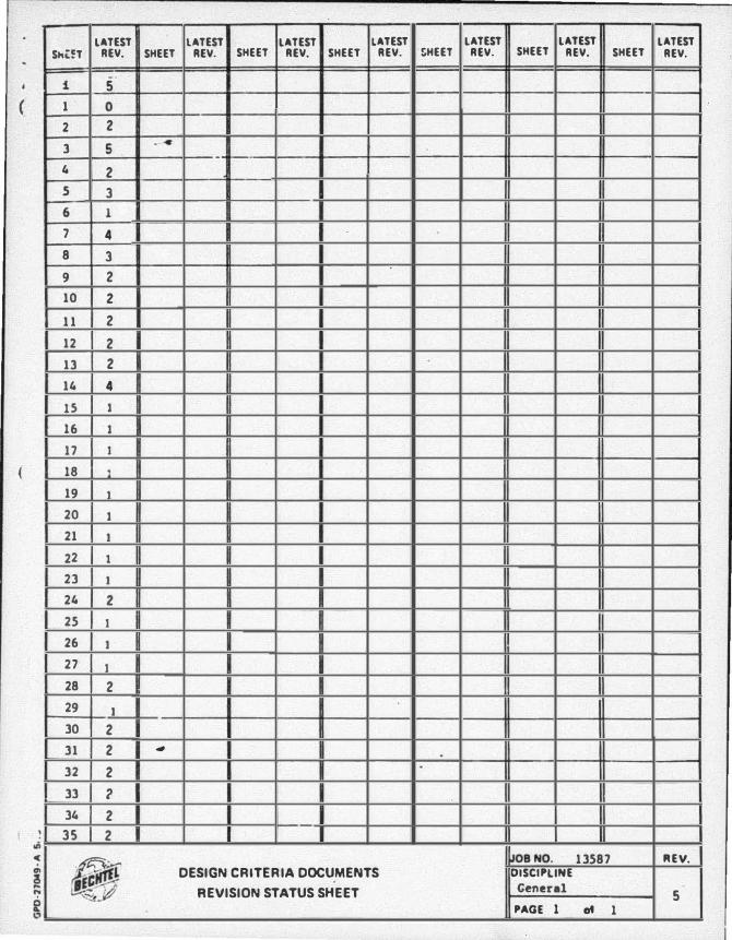
LATEST LATEST LATEST LATEST LATEST LATEST LATEST ShLfT REV. SHEET REV. SHEET REV. SHEET REV. SHEET REV. SHEET REV. SHEET REV.
1 5 ( 1 . 0
2 2
3 5 . . - 1-
4 2
5 3
6 l 7 4 8 3
9 2
10 2 11 2
12 2
13 2
14 4 15 1 16 1 17 1
( 18 ) 19 1 20 1 21 1 22 1 23 1 24 2 25 1 26 1 27 1 28 2
29 1 30 2
31 2 •
32 2 .
33 2 34 2
! 35 2
�:-. �OBNO. 13587 REV.
l DESIGN CRITERIA DOCUMENTS OISCIPLINE
� REVISION STATUS SHEET General 5 PAGE 1 of 1

Design Criteria 13587-2-l01-1CO
( TABLE OF CONTENTS
PAGE -•
1 . 0 GENERAL 1
1. 1 Introduction 1 1 . 2 Project Objectives 1 1.3 Project Concerns 2
2 . 0 DEFINITIONS 2
2 . 1 Safe Shutdown Earthquake (SSE) 2 2 .2 Operating Basis Earthquake (OBE) 2 2 .3 Seismic Category 1/Non-Seismic Category I 2 2 . 4 Design Bases 3 2 . 5 Safety Related 3 2 .6 Important to Safety (ITS) 3
3 .0 LICENSING 3
3. 1 Introduction 3 3 .2 Basic Criteria 3 3 .3 Design Conditions s 3.4 Regulatory Requirements 7 3 . 5 Industry Codes and Standards 8 3 .6 Safety Assessment 8
4 . 0 ALARA DESIGN CRITERIA AND CONSIDERATIONS 9
Table 1 Regulatory Guides 10 Table 2 AlARA Items 15 Table 3 Typical Radioactive Piping Classi ficatiun
and Routing 34 Table 4 Radiation Zones 35
1 Rev. 5
(
(
Design Criteria 13587-2-l01-100
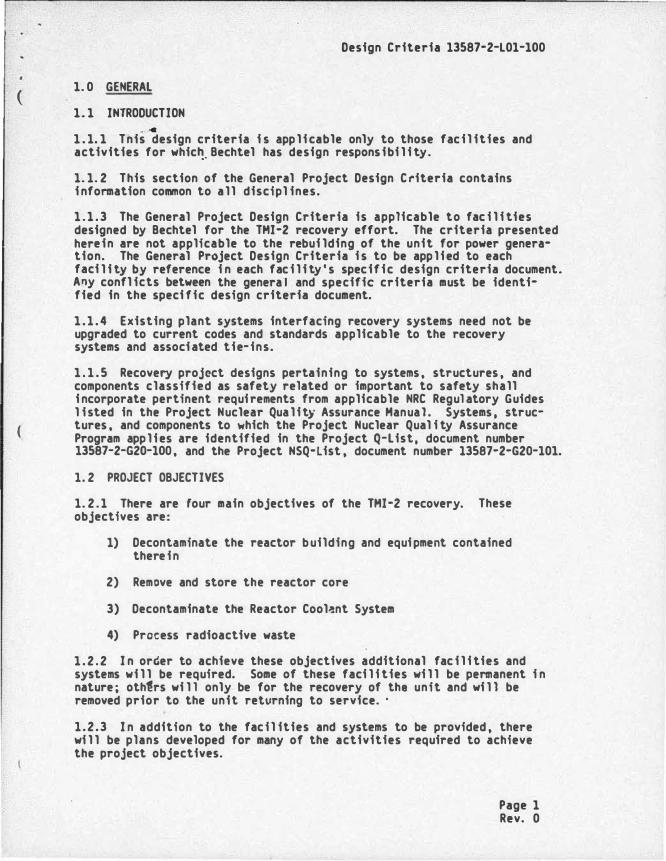
1. 0 GENERAL
1.1 INTRODUCTION ..
1 . 1. 1 Tnis design criteria i s appl icable only to those facil ities and activities for whic�. Bechtel has design responsibi l i ty.
1. 1. 2 This section of the General Project Design Criteria contains i nformation common to all discipl ines.
1 . 1 . 3 The General Project Design Criteria is applicable to fac i l i ties designed by Bechtel for the THI-2 recovery effort. The criteria presented herein are not applicable to the rebui lding of the unit for power generation. The General Project Design Criteria i s to be applied to each faci l i ty by reference i n each fac i l i ty's specific design criteria document. A�y confl icts between the general and specific criteria must be identified in the speci fic design criteria document.
1 . 1 . 4 Existing plant systems interfacing recovery systems need not be upgraded to current codes and standards applicable to the recovery systems and associated tie-ins.
1 . 1 . 5 Recovery project designs pertaining to systems. structures. and components classified as safety related or important to safety shall i ncorporate pertinent requirements from applicable NRC Regul atory Guides l isted in the Project Nuclear Quality Assurance Manual. Systems . structures. and components to which the Project Nuclear Qual i ty Assurance Program applies are identified in the Project Q-List. document number 13587-2-G20-100. and the Project NSQ-list. document number 13587-2-G20-101.
1. 2 PROJECT OBJECTIVES
1. 2 . 1 There are rour main objectives of the THI-2 recovery. These objectives are:
1) Decontaminate the reactor building and equipment contained therein
2) Remove and store the reactor core
3) Decontaminate the Reactor Cool�nt System
4) Process radioactive waste
1 . 2 . 2 I n order to achieve these objectives additional fac i l i ties and systems wi l l be required. Some of these faci l i ties wi l l be permanent i n nature; othfrs wi l l only be for the recovery of the unit and wi l l be removed prior to the unit retvrning to service. ·
1.2 .3 In addition to the facil ities and systems to be provided. there wi l l be plans developed for many of the activities required to achieve the project objectives.
Page 1 Rev. 0

(
(
Design Criteria 13587-2-LOl-100
1 . 3 PROJECT CONCERNS
1. 3.1 There are two v.ajor concerns that directly i nfluence the design of the faci11t1es and the operations required for the cleanup of THI-2. These concerns are:
1) Publ i c health and safety
2) Occupational health and safety
2 . 0 DEFINITIONS
2 . 1 SAFE SHUTDOWN EARTHQUAKE (SSE)
The safe shutdown earthquake i s that earthquake which i s based upon an evaluation of the maximum earthquake potential considering the regional and local geology and seismology and speci fic characteristics of local subsurface material . It i s that earthquake which produces the maximum vibratory ground motion for which certain structures, systems, and components are designed to remain functional .
2 . 2 OPERATING BASIS EARTHQUAKE (OBE)
The operating basis earthquake i s that earthquake which, considering the regional and local geolcgy and seismology and spec�fic characteristics of local sub�urface materia l , could reasonably be expected t� affect the plant site during the operating l ife of the plant; i t i s that· earthquake which produces the vibratory ground motion for which those features of the nuclear power plant necessary for continued operation without undue risk to the health and safety of the publ i c are designed to remain functional .
2 .3 SEISMIC CATEGORY I/NON-SEISHIC CATEGORY I
Seismic Category I structures, systems, and components for seismic design purposes are defined as those structures, systems, and components important to safety that are designed to remain functional in the event of a safe shutdown earthquake. Items that are both Seismic Category I and important to safety are those structures, systems, lnd components:
a. that are permanent plant components necessary to ensure the i ntegrity of the reactor coolant pressure boundary,
b. that are necessary to ensure the capabil i ty to shut d'wn the reactor or to maintain the reactor i n a safe shutdown condition ( i . e . , maintain subcritical ity and decay heat r�moval ), or to pr�ent a condi tion or event that could result i n a return to nuclear critical ity of fuel i nside or outside the reactor vessel, or
c . whose fai l ure could result in potential offsite exposures comparable to the guidel i ne values of 10 CFR Part 100. (Note: for the purpose of THI-2 recovery only, no events or accidents have been postulated which could result i n such offsite
Page 2 Rev. 2
2

(
(
Design Criteria 13587-2-L01-100
exposures. Therefore, it i s not expected that the guidel i ne val ues of 10 CFR Part 100 wi l l be i nvoked for design or operational-related activities during THI Unit 2 recovery.)
.. Non-Seisafc Category I structures, systems , and components are those whose failure would not result in the release of radioactivity in excess of 10 CFR 100 l imits· nor prevent reactor safe shutdown. ·
2 . 4 DESIGN BASES
Design bases are postulated events/conditio�s or combinations of events/ conditions which establish the function and structural requirements Gf a structure, system, or component.
2. 5 SAFETY RELATED
As used i n 10 CFR 100, Appendix A , this term refers to those structures , systems , or components designed to remain functional for the safe shutdown earthquake (SSE) necessary to ensure required safety functions, i . e. :
a . The i ntegrity of the reactor coolant pressure boundary
b. The capabi l i ty to shut down the reactor and maintain it i n a safe shutdown condition; or
c . The capabil i ty to prevent or mitigate the consequences of accidents which could result in potential offsite exposures comparable to the guidel ine exposures of 10 CFR 100.
Safety Related i s a subset of Important to Safety.
2 . 6 IMPORTANT TO SAFETY (ITS)
A special classification or category of those structures, systems , co�onents , and activities that provide reasonable assurance that the
�tl i ty can be operated without undue risk to the health and safety of IL puh It encompasses the broad class of plant features covered
(not nee ari ly expl icitly) i n the General Design Criteria (10 CFR SO Appendix �J that contributes i n important ways to the safe operation and protection of the public i n all phases and aspects of faci l i ty operation ( i . e. , normal operation and transient control as wel l as accident mitigation). It i ncludes "Safety Related" as a subset.
3. 0 LICENSING
3 . 1 INTRODUCTION -Recovery operations, activities , and work tasks·wfll be performed within the existing TMI-2 Technical Specifications and in accordance with applicable NRC Regulatory Guides. Speci fic design criteri8 shall identify applicable Technical Specifications and Regulatory Guide requirements.
Page 3 Rev. 5
5

(
Design Criteria 13587-2-L01-100
3. 2 BASIC CRITERIA
3 . 2 . 1 Facil ities and systems constructed to support the recove� shal l not be des�gged to requirements based on the hypothes i s of accidents at power.
3 . 2 . 2 Facil i ties and systems constructed for the l i re of the plant shall be designed to the applicable requi rements speci fied in Chapter 3 of the THI-2 FSAR i n addition to the requi rements necessa� for the recove�. The latest appl icable codes and standards wi l l be employed.
3 . 2 . 3 To the extent practicabl e , fac i l i ties and services constructed for the recovery effort wi l l be separate from exi sting fac i l i ti es and services.
Where it is not practicable to separate the fac i l i ties and services constructed for the recove� effort from existing fac i l i ties and services , design requi rements wi l l be imposed as necessa� in order not to compromise the original design bases of the existing fac i l i ties and services. These requirements shall be identi ft�d i n the specific design criteria for the fac i l i ty and service to be provided. The following wi l l serve as guidel ines:
a. Where piping and cables to be left in place when the unit i s r�turned to service are routed through bui l dings containing seismic Catego� I piping and cables, the fail ure of the nonseismic Category I components shal l not result i n the fai l ure of the seismic Catego� I components as a result of a seismic · event.
b. Where services to support recovery must tie into existing plant serv�ces , isolation provisions commensurate with the design requi rements of the existing plan� service shal l be provided.
c . Where piping to be left in place when the unit is returned to service i s routed through bui ldings conta1ning safety-related equipment, the requi rements for high energy l ine �reak and pipe whip specified in the TMI-2 FSAR shall be satisfied as appl icable.
d . Where cables to be left in place when the unit i� returned to service are routed through bui ldings containing safety-related equipment, the requirements for separation and fire protection specified in the THI-2 FSAR and TMI-2 Fire Protection Reevaluation shall be satisfied as applicable.
3 .2 .4 Fac i l i ties constructed to support the recovery effort shall not have as par� of their design basis the severe naturAl phencmena for which the plant was originally designed. Included under 11severe natural phenomena11 are:
a. Safe shutdown earthquake
b . Tornado and tornado missi le
c. Maximum flood. Page 4 Rev. 2

(
Design Criteria 13587-2-LOl-100
The faci l i ties wi l l be designed to ensure that there wi l l be no loss of requi red function of existing adjacent safety-related structures, equipment; or systems should these events occur .
. ... These faci liti es shall be designed for the more probable natural phenom-ena as called for b� area bui lding code requirements • . 3. 2 . 5 Fac i l i ties constructed to support the recove� shal l not be designed for man-made events not resulting fro� recove� activities. Inc�uded under "man-made events not resulting from recovery activities" are:
a . Transportation accident.s occurring offsite
b. Airplane crashes
c . Release of tohic c��micals .
The faci l i ties wil l be designed to ensure that there wi l l be no loss of required function of existing adjacent safety-related structures, equipment, or systems should these events occur.
3 .2 .6 Envi ronmental analyses will be performed in accordance with the methodology permitted by the Three Mile Island Nuclear Generating Station Offsite Dose Calculation Manual (ODCM). The s i te meteorology used for these analyses wi l l be based on that contained i n the ODCH.
( 3 . 2 . 7 For purposes of design evolution, the river characteristics speci fied in Chapter 2 of the THI-2 FSAR shall be used. River water qual ity data i s that specified i n the Plant Design and Mechanical Design Criteria, 13587-2-HOl-100.
3.3 DESIGN CONDITIONS
This section defines the spectra of operating conditions to which the activities required for the recove� �hal l be designed. Also provided are the general design requirements for these operating conditions.
3 .3 .1 Condi tion I - Normal Operation
Condition I occurrences are those that can reasonably be expected to occur during the recove� activities. Examples of Condi tion I occurrences are:
a . Those that are normal ly expected to ocrur·duri ng th� recovery including contami nation/decontamination resulting from routine activities.
b. Operations with equipment out of service or undergoi ng tests within operational l imitations.
Condition I occurrences shall be accommodated with only routine action required to prevent an unplanned release of radioactive materials in effluents to unrestricted areas.
Page 5 Rev. 3
3

(
(
Design Criteria 13587-2-LOl-100
3.3.2 Condition II - Incidents of Hoderlt! Frequency
Condition II occurrences are those any one of which may reasonably be exp�cted to occur during a calendar year and which could result i n a release of radioactive material requiring additional support personnel and/or equipment to control . Exampl es of Condition II occurrences are: ·.
a. loss of electrical power
b . Minor leakage from systems installed to support the recove�
c. Inadvertent actuation of a s i ngle active component i n a system installed to support the recove�
d. Single error by an operator engaged i n a recove� activity
e. Single active failure of a component (taken as the i ni tiating event) in a system i nstalled to support the recove�
Condition II occurrences shall be accommodated with, at most, a cessation of activities with the capabi l i ty of resuming the activities after corrective action. Any release of radioactive materials i n e#fl uents to unrestricted areas shall be i n conformance with Paragraph 20. 1 of 10 CFR Part 20, "Standards for Protection Aga1nst Radiation. "
3 . 3 . 3 Condition III - Infregue11t Incidents
Condition III occurrences are those which are not expected to occur but are a�sumed to occur during the l i fetime of the recove� effort and· could result i n a signi ficant release of radioactive material . Examples of Condition III occurrences are:
a. Rupture of any tank util ized for the recovery effort
b. Pipe break in a system instal led to support the recovery
c . Fire i n an area where recovery activities occur
d. An operating basis earthquake (OBE).
e. Fuel handl ing accident i n the reactor building (Note 2) .
Condition III occurrences may result in damage to recovery facil ities sufficient to preclude resumption of recove� activities for a considerable time. The release of radioactive material i n effluents to unrestricted areas may exceed the guidel ines of 10 CFR Part 20, "Standards for ProtecU.on Against Radiation,•• but shall not be. sufficient to interrupt or restrict public use of those areas beyo�d the exclusion radius.
Note 2: The source term for the postul ated occurrence i s based on assuming the assembly with the peak i nventory of radioactive material i n the THI-2 core i s i ntact. The burnup i s based on exact power histo�. Credit is taken for a decay period of It two years or more.
Page 6 Rev. 1

(
(
Design Criteria 13587-2-l01-100
3 . 4 REGULATORY REQUIREMENTS
3 . 4 . 1 Code of Federal Regulations
The facil iti\s and activities associated with the recovery shall sati sfy the fol l owing:
a. 10 CFR Part 20, Paragraph 20.103, Exposure of Individuals to Concentrations of Radioactive Katerials i n Air i n Restricted Areas
b. 10 CFR Part 20, Paragraph 20. 10S, Permi�sible level s of Radiation in Unrestricted Areas
c . 10 CFR Part 2�. Paragraph 20. 106, Radioactivity i n Effluents to Unrestricted Areas
d. 10 CFR Part SO, Paragraph S0. 34a, Design Objectives for Equipment to Control Releases of Radioactive Material in Effluents -Nuclear Power Reactors
e. 10 CFR Part SO, Paragraph S0. 36a. Technical Specifications on Effluents fro� Nuclear Power Reactors
f. 10 CFR Part SO, Appendix A, General Design Criteria for Nuclear Pwer Plants
g. 10 CFR Part SO, Appendix I, Numerical Guides for Design Objectives and limiting Condi tions for Operations to Meet the Criterion "As low As Is Reasonably Achievable" for Radioactive Material in light-Water-Cooled Nuclear Power Reactor Effluents, as specified by Appendix R of the Final Programmati c Environmental Impact Statement and i ncorporated i nto the TMI-2 operating l icense by Amendment No. 16
h. 10 CFR Part 100, Reactor Site Criteria
i . 29 CFR Part 1910, Occ-•Jpational Safety and Health Standards (Department of Labor Regulations)
j. 40 CFR Part 190, Uranium Fuel Cycle Standard (Environmental Protection Agency Regulations)
k. 49 CFR Part 173, Shippers-General Requirements for Shipments and Packagings (Department of Transportation Regulations)
1. 10'CFR Part SO, Appendix R, Fire Protection Program for Nuclear Power Fac i l i ties Operating Prior to Ja�uary 1, 1979 (Exemption has been requested for Sections III G and III J per GPUNC letter 4400-82- L-0102, dated June 1S, 1982, J . J. Barton to Dr. B. J. Snyder. These sections of Appendix R wi l l not be implemented during the recovery effort.)
•· 40 CFR Parts 260 through 26S, Hazardous Waste Regul ations (Environmental Protection Agency Regulations)
Page 7 Rev. 4
4

(
(
Design Criteria 13587-2-l01-100
3 .4 .2 RegulatorY Guides
Table 1 l ists �any of the regulatory guides which may be appl icable to individual faci l ity or system design. This table and other regulatory guides sha11 be reviewed and any regulatory guides to be implemented shall be included as part of the specific design criteria for the associated fac i l i ty or system.
3 .4 .3 Standard Review Plans (SRPs)
The following SRPs and Branch Technical Positions shall be reviewed and the guidance provided used as applicable i n designing the fac i l i ties and activities to support the recovery.
a . SRP 11.2. liquid Waste Management Systems, Rev. 1
b. SRP 11. 3 , Gaseous Waste Management Systems , Rev. 1
c . SRP 11.4. Sol id Waste Management Systems, Rev. 1
d. SRP 15. 7. 3, Postulated Radioactiv� Releases Due to liquid Containing Tank Fai lures. Rev. 1
e. Appendix A to Branch Technical Position APCSB 9 . 5-1, Guidel ines
r for Fire Protection for Nuclear Power P lants Docketed Prior to July 1, 1976 (August 23 , 1976)
f . Branch Technical Position ETSB 11-3, Design Guidance for Sol i d Radioactive Waste Management Systems Instal led i n light-WaterCooled Nuclear Power Plants , Rev. 1
3 .4 .4 State Regulations
The facil ities and activities associated with the recovery shall satisfy the fol lowing:
Title 25, Envi ronmental Resources; Chapter 75, Solid Waste Management (Pennsylvania Department of Environmental Resources Regulations)
3 . 5 INDUSTRY CODES AND STANDARDS
Appl icable i ndustry codes and standards are identified in the individual discipl ine design criteria.
3 .6 SAFETY ASSESS�ENT
A safety assessment wi l l be performed for each�aci l i ty and activity to be provided. This assessment shall i nclude a review of the final design to ensure that the safety criteria have been satisfied. When the assessment reveals that the final design does not sati sfy the safety criteria. design changes shall be made or administrative controls imposed.
Page 8 Rev. 3

(
Design Criteria 13587-2-L01-100
4 . 0 ALARA DESIGN CRITERIA AND CONSIDERATIONS
The items l i sted i n Table 2 form the basis for the TMI-2 Recover,y Project ALARA program. During the design process, the appl icable items shall be con!idered and i ncorpor�ted i nto the design as appropriate.
-
Page 9 1 2 Rev. 2

(
I '
1. Reg. Guide 1. 21
Discussion
Design Criteria 13587-2-l01-100
TABLE 1
REGULATORY GUIDES
- Measuring, Evaluating, and Reporting Radioactivity i n Sol id Wastes and Releases of Radioactive Materials i n liquids and Gaseous Effl uents from Light-Water-Cooled Nuclear Power Plants (Rev. 1 , June 1974)
This guide i s applicable to the design of radiation monitoring systems i n l i quid and gaseous effluent paths and i n the design of means for determi ning the total c�rie quantity and radionucl ide composition of sol id wastes shipped offsite with the fol lowing clarification.
(1) (Ref: Appendix A, Paragraph C) To preclude unnecessary radiation exposure to personnel , the curie and radionucl ide determinations for solid radioactive waste shipped offsite wi l l be performed to the extent and level required by Department of Transportation Regulations and 10 CFR Part 71, "Packaging of Radioactive Material . " Additional sampl i ng and analysis i s not required.
2. Reg. Gui�. 1 .25 - Assumptions Used for Evaluating the Potential Radiological Consequences of a Fuel Handl i ng Accident i n the Fuel Handl i ng and Storage Faci l ity for Boi l i n� and Pressurized Water Reactors (Rev. 0 , March 1972)
Discussion
The assumptions of the guide may be used with the fol lowing exceptions or clarifications, i n the analysis of the potential radiological consequences of a fuel handl i ng accident.
(1) [Ref: Paragraph C .3 . b(2)] Whole-body gamma doses and beta-skin doses are presented separately, as the dose from beta radiation of the whole body i s negl igible. The total dnse to the skin i s the s um of the beta-skin dose and the whole-body gamma dose.
(2) [Ref: Paragraph C . 3. b(3)] Dose conversion factors are taken from Reg. Guide 1. 109.
�
(3) ( Ref: Paragraph C .l) The source term:for the postulated fuel handl i ng accident is based on assuming the assembly with the peak invenl�ry of radiaoctive material i n the THI-2 core i s i ntact. The burnup i s based on exact power hi story. Credit i s taken for a decay period of two years or eore.
Page 10 I 2 Rev. 2

(
Design Criteria 13587-2-L01-100
TABLE 1 (Continued)
3. Deleted . . 4. Deleted
s.
6.
Reg. Guide 1. 60
Discussion
- Design Response Spectra for Seismic Design of Nuclear Power Plants (Rev. 1, December 1973)
This guide is appl icable to fac i l i ties housing radioactive waste management systems and subject to and as invoked by Reg. Guide 1. 143.
Reg. Guide 1.61
Discussion
- Damping Values for Seismic Design of Nuclear Power Plants (Rev. 0, October 1973)
This guide i s appl icable to facil ities housing radioactive waste management systems and subject to and as i nvoked by Reg. Guide 1 . 143.
7 . Deleted
8. Reg. Guide 1 . 92
Discussion
- Combining Modal Responses and Spatial Components i n Seismic Response Analysis (Rev. 1, February 1976)
This guide i s applica�le to facil ities housing radioactive wastP. management systems and subject to and as invoked by Reg. Guide 1 . 143.
9. Reg. Guide 1. 109 - Calculation of Annual Doses to Han from Routine Releases of Reactor Effluents for the Purpose of Evaluating Compliance with 10 CFR Part 50, Appendix I (Rev. 1, October 1977)
Discussion
The assumptions of Regulato� Guide 1 .109 are fol lowed i n the analysis of annual doses to man from routine releases.
10. Deleted
11. Reg. �ide 1. 112 - Calculation of Releases of Radioactive Materials i n Gaseous and liquid:Effluents from light-WaterCooled Power Reactors (Rev. 0 , April 1976)
Discussion
The appl icable methods described in this guide may be used i n calculating estimated releases from l iquid waste processing systems.
Page 11 Rev. 2
2
12
12
12

(
(
12. Reg. Guide 1. 113 -•
Discussion
Design Criteria 13587-2-L01-100
TABLE 1 (Continued)
Estimating Aquatic Dispersion of Effluents from Accidental and Routine Reactor Releas�s for the Purpose of· Implementing Appendix I (Rev. 1, April 1977)
The applicable methods described i n this guide may be used i n estimating aquatic dispersion of effluents.
13. Reg. Guide 1. 132 - Site Investigations for Foundations of Nuclear Power Plants (Rev. 1, March 1979)
14.
15.
16.
Discussion
Recognizing the site-sensitive aspects, the guidance provided by this guide may be used i n the devel opment of site investigation studies for foundations of faci l i ties to be provided.
Reg. Guide 1. 13� - Laboratory Investigations of Soi l s for Engineering Analysis and Design of Nuclear Power Plants (Rev. 0 , April 1976)
Discussion
Recognizing the site-sensitive aspects, the guidance provided by this guide may be used i n the laboratory investigations of soi l s requi red by Reg. Guide 1. 132.
Reg. Guide 1. 140 -
Discussion
Design. Testing, and Mai ntenance Criteria for Normal Venti lation Exhaust System Air filtration and Adsorption Units of Light-Water-Cooled Nuclear Power Plants (Rev. 1 , October 1979)
The detai led project position i s ur.der development. However, this guide i s appl icable to atmosphere cleanup systems and, in general. the guidance provided may be fol lowed.
Reg. Guide 1. 143 - Design Guidance for Radioactive Waste Management Systems , Structures, and Components Installed i n light-Water-Cooled Nuclear Power Plants (Rev. 1 , October 1979)
Page 12 Rev. 2

(
(
Design Criteria 135e7-2-l01-100
TABL� 1 (Continued)
Discussion
This guide i s appl icable to systems and fac i l i ties that are associated with t�e control and management of l i quid, gaseous, and sol i d radioactive waste. (Note: radioactive waste means those l iquids , gases, or sol ids containing radioactive materials that by design or operating practice wi l l be processed prior to finAl di sposition. ) j2
17. Reg. Guide 8. 8 - Information Relevant to Ensuring That Occupational Radiation Exposure at Nuclear Power Stations Wi l l Be as low as I s Reasonably Achievable (Rev. 3, June 1978)
Discussion
The design considerations , personnel qual i fications, and plans and procedures for ensuring that occupational radiation exposures wi l l be as low as i s reasonably achi�vable are i n accordance with Regulatory Guide 8. 8 subject to the following clari fications or exceptions:
(1) (Ref: Paragraph C.2) The design features discussed in this paragraph are described in general terms which may permit several acceptable alternative designs for a particular application, e.g. , different types or amounts of shielding.
(2) (Ref: Paragraph C . 2. g) Ai rborne monitoring equipment will be provided in areas to which personnel normally have access and in which there i s a potential for airborne radioactivity. I n addition, area radiation monitors will be provided in areas to whtch personnel normal ly have access and where there i s a potential for personnel unknowingly receiving high levels o, radiation exposure (e. g. , in excess of 10 CFR 20 l imits) in a short period of time because of system failure or improper personnel action.
Note: For guidance on the following Regulatory Guides, consult the Bechtel Nuclear Qual ity Assurance Manual (NQAH).
1 . 26 QA Classi fications and Standards for Water Stream and Radioactive Waste Containing Components of Nuclear Power Plants, Rev. 3 , February 1976 �
1. 29 Seismic Design Classification, Rev 3 ,• September 1978.
1 . 30 QA Requi rements for the Instal lation, Inspection and Testing of Instrumentation and Electrical Equipment, August 11, 1972.
1. 31 Control of Ferrite Content i n Stainless Steel Weld Metal, Rev. 3, April 1978.
Page 13 Rev. 2
2

(
(
l
Design Criteria 13587-2-L01-100
TABLE 1 (Continued)
1. 37 QA Requirements for Cleaning of Fluid Systems and Associated Canponents of Water Cooled Nuclear Power Plants, March 16 , 1973.
1 . 38 QA Requi rements for Packaging, ·Shipping , Receiving, Storage and Handl ing of Items for Water Cooled Nuclear Power Plants, Rev. 2 , May 1977.
1 . 39 Housekeeping Requi rements for Water Cooled Nuclear Power Pl ants , Rev. 2 , September 1977.
1. 54
1 .94
1. 116
QA Requirements for Protective Coatings App l i ed to Water Cooled Nuclear Power Plants , June 1973.
QA Requirements for Instal lation , Inspection and T�sting of Structural Steel and Concrete during the Construction Phase of Nuclear Power Plants, Rev. 1, April 1976.
QA Requirements for Installation, Inspection and Testing of Mechanical Equipment and Systems , Rev. 0-R , Hay 1977.
--
Page 14 Rev. 4

Design Criteria 13587-2-L01-100 1
TABLE 2 + ( ALARA ITEMS
Item - . No. DescriEtion Res2onsibil ities Note
Sec. A FACILITY ARRANGEMENT
1 . 0 Facil it� La�out
1 . 1 Check that equipment with contact radiation levels of Zone III (see
N *
Table 4) or greater i s separated from Zone II and lower areas by shielding or distance plus access barriers.
1 . 2 Check that major equipment which by N design accumulates or concentrates radioactivity with Zone III or greater contact radiation levels i s shielded or separated from adjacent active and passive equipment to meet the appli-cable radiation shielding criteria for adjacent areas.
( 1. 3 Check that equipment compartments are arranged such that radiation zone
N *
di fferences between adjacent areas are minimized.
1 . 4 Check that personnel access control A, N , PO and traffic patterns are considered to minimize spread of contamination during all fac i l i ty operating modes.
1 . 5 Check that active components i n clean H (nonradioactive) services are not located i n Radiation Zone III or greater.
1.6 Check that equipment subject to removal PO or replacement has adequate aisles or area access and bui l t-in provisions (such as monora i l s , jib cranes , etc. ) ffM" removal.
1 . 7 Check that access to components PO requiring frequent maintenance, i n-service inspection, adjustment, etc. i s from the lowest practicable radiutfon zone and not via a Zone V.
Page 15 Rev. 1
Design Criteria 13587·2·L01·l00 1
TABLE 2 (Continued) + ( I tem
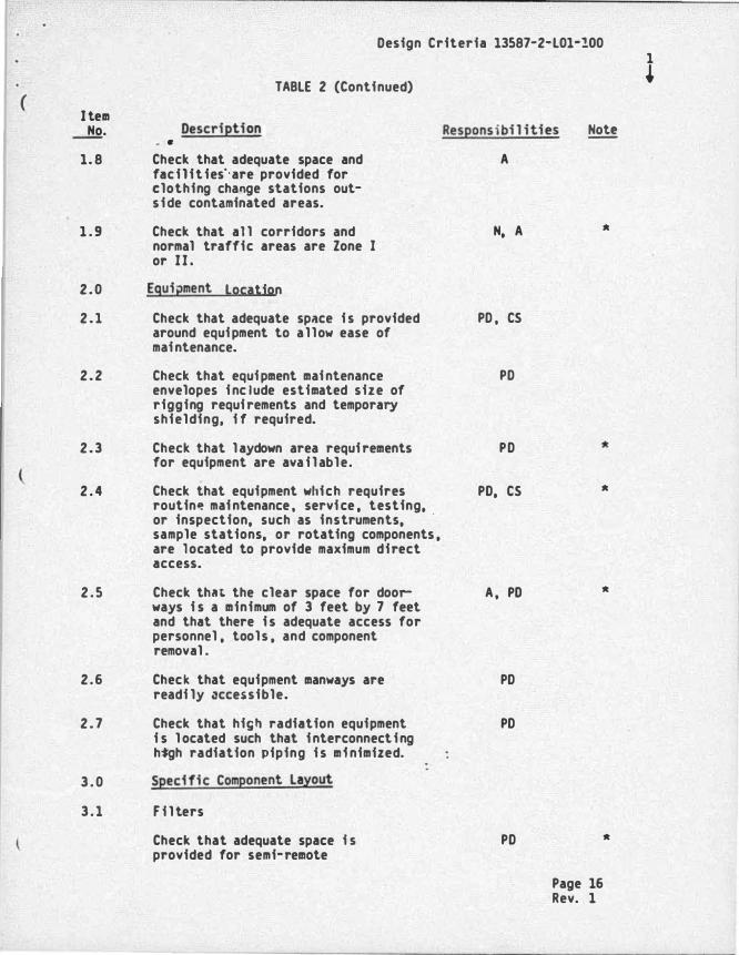
No. Description Responsibi l i ties � . . 1. 8 Check that adequate space and A
facilities··are provided for clothing change stations out-side contaminated areas.
1 . 9 Check that al l corridors and N, A *
normal traffic areas are Zone I or II.
2 .0 Egui2ment Location
2 . 1 Check that adequate sp�ce i s provided around equipment to allow ease of
PO, CS
maintenance.
2 .2 Check that equipment maintenance envelopes include estimated size of rigging requirements and temporary shielding, i f required.
PO
2 .3 Check that laydown area requirements for equipment are available.
PO
2 . 4 Check that equipment which requires routin� maintenance, service , testing,
PO, CS *
or inspection, such as instruments, sample stations, or rotating components , are located to provide maximum direct access.
2 . 5 Check that the clear space for door- A, PO *
ways i s a minimum of 3 feet by 7 feet and that there i s adequate access for personnel , tools , and component removal .
2 .6 Check that equipment manways are PO readi ly accessible.
2 . 7 Check that high radiation equipment i s l ocated such that interconnecting
PO
high radiation piping i s minimized.
3 . 0 Specific Component La�out
3 . 1 F i lters
Check that adequate space i s PO *
provided for semi-remote
Page 16 Rev. 1

Design Criteria 13587-2-l01-100 1
( I tem
TABLE 2 (Continued) �
� • Description Responsibilities Note
1·emoval, cask loading, and trans-porting sp�nt radioactive fi lter cartridges to the sol id ra�aste area. ·
3 .2 Pumps
3 . 2 . 1 Check that smal l pumps are oriented i n a manner that allows easy removal
PO
from the area.
3 . 2 . 2 Check that adequate access is provided PO for pump seal replaceDent.
3 . 3 Tanks
3 . 3 . 1 Check that direct access and removal PO space is provided for motors of tank agitators.
3 . 3 . 2 Check that di rect access to active PO
( components or manways i s provided i nto the upper levels of tank rooms as well as the lower elevations.
3 .3 .3 Check that adequate space is provided for tank internals cleaning operations.
PO
3 .4 Evaporators
3 .4 .1 Check that concentrates and PO disti l late components are adequately separated.
3. 4 . 2 Check that components which accumulate PO, N radioactivity or crud, such a� heating tubes, are separated from active com-ponents such as valves.
3. 4 .3 Check that adequate space is provided PO to al low uncomplicated removal of heeting tube bundles.
3. 5 Sample Stations
3 . 5 . 1 Check that sample stations for routine sampling of process fluids
PO, N , CS
are separated by shielding or distance from other radic1ctive components to Zone II.
Page 17 Rev. 1

Design Criteria 13587-2-l01-100 1
TABLE 2 (Continued) + (
Item No. - . Description Responsibil i ties �
3.5.2 Check that local ventilation (e.g. , PO, N , CS a hood) i s""provided at sample stations containing radioactive materials.
3. 6 Ventilation System Components
3 .6 .1 Check that ventilation fans and PO filters are provided with adequate a�cess space to permit servicing.
3.6.2 Check that outside air supply and PO building exhaust system components are i n areas no greater than Zone II.
3. 6.3 Check that general ventilation flow i s PO from areas of potential (or actual ) low contami nation to areas of potential (or actual) high contami nation.
3.7 Instruments
( 3 . 7 . 1 Check that i nstruments which require cs periodic attention are l ocated i n Zone II (or lower) areas whenever possible.
3. 7.2 If instruments must be located in PO, CS Zone III or greater , check that they are � unted so that they are readily accessible for maintenance and cal ibration and are easily removable to a lower radiation zone for extended servicing or calibration.
3. 7 . 3 I f control valves must b e l ocated i n P O , CS Zone IV or greater, check that appur-tenances such as E/P converters , airsets , and solenoid valves are not mounted on the control valve but are l ocated i n a lower radiation zone.
3.8 StStnps
Check that sumps capable of PO accumulating radioactive wastes ar� located i n zones compatible with radiation levels due to the contained activity.
Page 18 Rev. 1

( Item
No.
Sec. B
1 . 0
1. 1
1 . 2
1 . 3
1 . 4
l.S
1 . 6
2.0
2 . 1
2 . 2
2. 3
Design Criteria 13587-2-l01-100
TABLE 2 (C�ntinued)
Description Responsib i l i ties Note •
SHIELDING
Bul k Shielding
Check that shielding or separation is provided between radiation zone are�s to meet the radiation level criteria for adjacent areas.
Check that shielding design is based on conservative or measured radiation source term, component design, and plant layout assumptions.
Check that poured concrete density specifications are consistent with shielding design basis minimum densities.
Check that concrete block density speci fications are consistent with shielding design basis minimum densities.
Check that concrete block wall designs meet or exceed the minimum shielding requirements.
Check that removable or tempera� shielding i s designed consistent with applica�le radiation shielding criteria for adjacent areas.
Penetration and Di scontinuit� Shielding
Check that penetrations, such as H&V ducts and piping, are either located with an offset between radiation sources and accessible areas or are appropriately shielded.
Check that penetrations are located as . far as possible above the accessible floor elevation.
Check that penetration shielding i s provided a s necassary to meet the radittion shielding criteria i n adjacent accessible areas.
N
N
N , C
N , A
N, A
N
N, PO , E, CS
N , PO, E , CS
N
Page 19 Rev. 1
1 +

(
Design Criteria 13587-2-L01-100
Jte111 ..1!2:. 2.4
TABLE 2 (Continued)
• Description
Check that seismic gap shielding i s provided tb 111aintain radiation levels in adjacent accessible areas within radiation shielding criteria l i�nits.
3 . 0 Entryway Shielding
3 . 1
3 . 2
Sec. C
1.0
1. 1
1 . 2
1. 3
1 . 4
1. 5
Check that there i s no direct or near direct shine out of shielded cel ls .
Check that adequately shielded labyrinths or hatches are provided to l imit direct and scattered r�1iation out of shielded areas.
SYSTEM DESIGN
Decontamination Provisions
Check that radioactive systems with Zone V component radiation levels have provisions to flush the entire system. Flushing capabi l ity should be available even i f the system pump i s inoperable.
Check that major components of the primary cool a1it. p!.lrification system where crud can collect up to Zone V radiation levels , such as fi lters, heat exchangers , etc. have provi sions for chemical decontamination, i ncluding low point drains. Check that means are available to take the decon solution to chemical waste area.
Check that seal flush water i s provided to pumps with chemical or sh•rry wastes.
Check that al l serviceable components heve isolating and draining capab i l i ty.
·check that provisions are available to flush potentially contaminated instrument l i nes.
Responsib i l i ties
H, C
Note
N
N
M, PO
M , PO
M, PO
M, PO, CS
M, PD , CS
Page 20 Rev. 1
1 +

Design Criteria 13587-2-L01-100
TABLE 2 (Continued) l ( Item
No. Description Responsibi l ities � - . 1.6 Check that flush connections are M, PD
located downstream of the component isolation valve on the i nlet l ine and upstream of the isolation valve on the outlet l ine, and as close as possible to the i nlet and outlet connections of the component.
1 . 7 Check that isolation valves are H , PO provided on the flush connections and are located as close as possible to the main pipe.
1. 8 Check that all flush connections are H , PO equipped with quick connect/di sconnect fittings.
2 . 0 Remote Operation and Instrumentation
2 . 1 Check that adequate process i nstrumen-tation and controls are available to
cs
allow system and component operation ( from a low radiation zone.
2 .2 Check that filters which accumulate PO high radioactivity are designed with the means either to backflush the filter remotely or to perfo� cartridge repl acement with semi-remote tool s .
2 .3 Check that probe type instruments are used on highly radioactive tanks con-taining two-phase materials .
cs
3.0 leakage Provisions
3. 1 Check that tank overflow l i nes are PO directed to the waste collection system.
3.2 Check that sl udge tanks and air �ixing PO tanks which contain radioactive materials are vented to the respective. bui lding ventilation system or the vent col lection system.
3 .3 Check that strainers are incl uded i n PO vent l i nes from tanks containing spent resins or sludge.
Page 21 Rev. l

Design Criteria 13587-�·L01-100 1
TABLE 2 (Continued) � (
I tem � • Description Responsibil ities Note
4 . 0 Oemineral izers o;o--
4 . 1 Check that demineralizers i n radio· PO active systems and associated piping are designed with provi sions for being flushed with demineral ized water.
4 . 2 Check that strainers are located immed- PO iately downstream of ion exchangers.
4 . 3 Check that drains and downstream M, PO strainers are designed for full sys-tem pressure drop.
4 .4 Check that strai ners are i ncluded PO i n vent l i nes from the demineral izer vessel .
4 . 5 Check that flush connections are PO provided at all critical locations
( (such as elbows, ties, valves) to clear potential plugs.
4 .6 Check that flow i n piping i s turbulent M enough to ma intain suspension of fines.
5 . 0 Floor Drains
5. 1 Check that equipment drains are piped directly to a drainage
PO
col lection system.
5 . 2 Check that provisions are made to PO remove plugging should it occur i n drain l i nes.
5 . 3 Check that radioactive and potentially PO radioactive drains are sepdrated from nonradioactive drains.
Sec. 0 ptpJNG AND VALVE DESIGN
1 . 0 Pipe Routing
1. 1 Check that piping contai ning radio- PO active materials i s routed through suitably zoned, control led access areas in accordance with piping
Page 22 Rev. 1

( I tem No.
1.2
1 . �
1 . 4
1. 5
2.0
2.1
2. 2
2.3
2.4
2. 5
Design Criteria 13587-2-L01-100
TABLE 2 (Continued)
•
radiation classification as shown i n Ta�le 3. ·.
Check that equipment compartments contain radioactive piping associated only with equipment within the compart-ment or that nonassociated piping i s adequately separated.
Check that where i t f s necessary for radioactive piping to be routed through corridors or other radiation zone areas , shielded pipeways are provided to meet area radiation level requirements.
Check that long runs of exposed radioactive piping are minimized, particularly in active componer.t areas such as valve galleries or pump cel ls .
Check that radioactive piping is routed to take credit for shielding effects of equipment or structures.
Valve location
Check that valves are separated from components which accumulate or contain radioactivity by shielding or distance to meet the applicable radiation shielding criteria levels.
Check that valves are readily access!-ble from floors or permanent platforms.
Check that sufficient space i s pro-vided to faci l i tate valve and valve operator mair.�enance, operations, and testing.
, Check that valves are not located fn radioactive pipeways.
Check that vent and drain isolation and instrument root isolation valves are located as close as practical to process pfpfng or components .
Reseonsibi l i ties Note
PO
PO, N
PO
N , PO
N , PO
PO, cs
PO , CS
: PO , cs
PO , cs
Page 23 Rev. 1
1 J

( Item No.
2 . 6
2 . 7
3 . 0
3 . 1
3 .2
3 .3
3. 4
3 . 5
3 .6
3 . 7
3 . 8
Design Criteria_ 13587-2-l01-100
l'ABLE 2 (Continued)
• Responsibil ities iiote
Check that process valves are not PO l ocated at' low points i n piping.
Check that reach rods or remote PO, N manipulators are provided for manually operated valves that are required in potential ly high radi-ation areas (Zone V or greater).
Pipe Design
Check that branch l ines having l ittle PO or no flow during normal operation are connected above the horizontal midplane of the main pipe.
Check that thermal exp�nsion loops i n PO radioactive systems are raised rather than dropped.
Check that orifices are located on PO, CS vertical piping runs if possible. located in horizontal piping runs,
If
use ecrentric design of the orifice.
Check that reducer:; are installed not PO to form a stagnant pocket, i . e. , l•se eccentric design with bottom flat, except at pumps.
Check that orifices located in hori-zontal runs use an eccentric design only if suspended sol ids are present in the process fluid.
Check that lenglhs of radioactive pipe runs and number of bends are minimized.
Check that low points and dead legs i n radioactive piping are minimized and are capable of being fl ushed. -Check that instrument and sensing l i ne connections are located in such a way as to avoid corrosion product and radioactive gas buildup.
PO , CS
PO
PO
PO, CS
Page 24 Rev. 2
2

( I tem No.
3 .9
4 . 0
4 . 1
4 . 2
( 4 . 3
4 . 4
4 . 5
4 . 6
4 . 7
Design triteria 13587-2-l01·100
TABLE 2 {Continued)
• Check that welded joints are used when-ever possible to minimize crud traps i n the mechanical joints.
Valve and Valve O�erator Selection
Check that full ported valves are used i n systems expected to handle spent resins or sl urries with radiation levels of 25 mr/hr or greater at con-tact with the surface of the Ph•e. {See Table 3)
Check that valves 2-� inches and larger (except butterfly valves and plug valves) i n l i nes carrying radioactive fluids with radiation levels of 25 mr/hr or greater {con-tact do$e rate) are di aphragm, pack-less, or havP. a double set of packing with lantern ring.
Check that all globe valves i n drain l i nes {excluding instrument valves) 2 i nches and smal ler are Y-pattern globe valves to faci l i tate redding i f plugging should occur.
Check that remote operators or handwheels on reach rods are provided for all valves, which must be accessible during operation, i n l i nes processing evaporator bottoms or spent resins.
Check that pressure relief valves have flange connections to fac i l i tate remov�l for set pressure verification and cal ibration.
Check that valve operators are PEPPerly selected and meet the criteria i n Table 3.
Check that valve types are properly selected for their intended ser-vice and environment.
Res�onsibi l i ties Note
PO, CS
H , PO , CS
H , PO, cs
H , PO
H , PO , CS
H , PO
H , PO
H , PO
Page 25 Rev. 1
1 +

Design Criteria 13587-2-L01-100 1
TABLE 2 {Continued) + (
I tem No. •
Responsibil i ties � 4 . 8 Check that plug valves or equal are M, PD
used on systems transporting resins and sludge, and on radwaste systems.
5 . 0 Spent Resin and Sludge Piping
5. 1 Check that resin l i nes are continuously PD sloped i n the direction of flow to avoid potential stagnant pockets.
5.2 Check that valves are located as close PD as possible to the spent resin tank room to minimize the length of the dead leg.
5.3 Check that flow control valves and M, CS orifices are not used in resin l i nes.
5 .4 Check that long radius (1. 5 times the PD pipe diameter or greater) bends and elbows are used at direction changes.
( 5. 5 Check that directional changes i n PD resin piping runs are minimized.
5 . 5 Check that fluid velocity i s high PD enough to keep resins in suspen�ion.
5 . 7 Check that system design permits flow ro to be continuous until resins are flushed from piping, or provision i s made for flushing at a velocity hi�h enough to pick up resi�s that h��� settled out during flow interruption.
Sec. E COMPONENT OESIGH (For components contain-1ng rad1oact1ve fluids or located in high radiation areas)
1 . 0 Specifications
1. 1 Check that material requisitions specify t�e radiation environmental requirements .
H, CS
for the intended material appl ication.·
1. 2 Check that equipment design features M, CS as presented in the remainder of this section are i ncluded i n the appropriate equipment specification.
Page 26 Rev. 1

( Ite• ..1!2:. 2 . 0
2 . 1
2 . 2
2 . 3
2 . 4
2 . 5
3 . 0
4 . (1
4 . 1
4 . 2
4 .3
4 .4
4 . 5
Design Criteria '13587-2-L01-100
TABLE 2 (Continued)
Responsibil ities Note •
Heat Exchangers
Check that corrosion-resistant tubes H of stainless steel or other suitable •aterial with welded tube-to-tube sheet joints are provided to minimize leakage.
Check that impact baffles are provided H with tube side and shell side velocities l imited to minimize erosive effects.
Check that drains are provided on the lowest portion to ensure removal of contaminated fluids.
H, PO
Check that where practical the contam- H inated side of the heat exchanger operates at a lower pressure than the clean side.
Check that the more radioactive stream i s on the tube side.
Evaporators
Check that chemical addition connec-tions are provided to allow use of chemical s for descal ing operations.
Pumps ( Sma 1 1)
Check that pump casings are provided with drain connections.
Check that pumps in radiation areas (Zone I I I or higher) are purchased with mechanical seals to reduce seal servicing time and leakage.
Check that pumps in radioactive systems are provided with flanged connections for ease i n removal .
4 Check that electrical quick disconnects are provided on pumps i n high radiation zones (V or higher).
Check that painted surfaces of the pump ( i f any) are painted with a radiation-resistant and decontaminable coating.
H
H
H
H
H
H , E
H , A
Page 27 Rev. 1
1 �

(
\
Design Criteria 13587-2-L01-100
TABLE 2 (Continued)
I tem No. Responsibi l i ties
4 . 6
4 . 7
•
Check that the pump has long· l ived bearings and that lubrication i s the pennanent type.
Check that the pump selection has considered the use of l ow RPM designs.
5. 0 Tanks
5. 1
5 . 2
5 . 3
5 . 4
5 . 5
5 .6
5. 7
5 .8
Check that tanks in radioactive service are provided with sloped bottoms (win. 1 inch per foot of tank diameter) and bottom outlet connections. Conical or dished bottom tanks with bottom connections are acceptable.
Check that adequate tank mixing i s provided to prevent crud settl ing.
Check that each tank requiring a manway i s top fitted with one of at least a 2-foot diameter. ( I f a manway is located on the side of a tank, i t should be clearly demonstrated that i t is necessary. )
Check that side manways have eccentrically hinged covers designed to easily clear fastening studs.
Check that outlet pipes have backflushing capabi l i ty into the tank to break up sediment. Backflush capabi l i ty should i ncl ude air.
Check that tank l i nings ( i f any) are sui table for the expected service.
Check that overflow l i nes are lower than vent l ines to prevent fluid from c�ntaminating vent l i nes.
Check that a permanent connection i s provided for insertion o f a hydrolaser unit for decontamination of tanks in Zone V areas.
H
H
H, C
H
H, C
H, C
H , PO
H , C , A
H, PD, C
H , PO , C
Page 28 Rev. 2

( Item No.
5 . 9
5 . 10
5 . 11
5. 12
5 . 13
5. 14
6 . 0
6 . 1
6 . 2
6 . 3
Design Criteria 13587-2-L01-100
TABLE 2 (Continued)
•
Check that 1£p joints were not used in tank const�uction.
Check that no backing strips were used on tank welds.
Check that backing rings were not used on nozzle welds.
Check that siphoning of l i quid waste f;om tanks cannot occur.
Check that in- l i ne filters with backflushing capabi l i ty are provided for tanks with a sl udge buil dup potential .
Check to ensure that tanks with a potentially hazardous leakage conse-quence are located over catch pans or within curbs with drain l i nes leading to radioactive l i quid waste storage tanks or to sumps capable of handling a potential spi l l .
Instruments
Check that chemical seals are provided on sensing l i nes on process piping that may contain high amounts of sol ids.
Check that primary instrun.ents which, for functional reasons , are located i n high radiation zones (V and gre&ter) are designed for easy removal to a radiation Zone I I or lower for cal ibra-tion.
Check that instruments are selected which contain minimal quantities of contaminated working fluids: e .g . , pressure transducers rather than bel l ows-type pressure gauges.
Reseonsibi l i ti es Note
"· c
"· c
"· c
PD
PO
H , PO
cs
cs
cs
Page 29 Rev. 1
1 *

( Item � 7. 0
7. 1
7 . 2
7 . 3
7 . 4
( 7. 5
7 . 6
Sec. F
1 .0
1. 1
1 . 2
Design Criteria 13587-2-L01-100
TABLE 2 (Continued)
•
Tool s . Check that tool design has mini�i%ed cracks and crevices.
Check that corrosion-resistant materials have been used for tool construction (where a?pl icable) and that the materials and surface finishes are conducive to decon-lamination.
Check that tool design allows for flushing of potentially contaminated surfaces (inside and out).
Check the design to ensure that tool s can be easily ass�mbled/disassembled with simple hand tools and that the design incorporates features to ei ther minimized instal lation time or provide for remote installation.
Check that al l flush connections ( i f applicable) have quick connect/ di sconnect fittings.
Check that tool hangers and storage areas are accessible and serviceable.
MISCELLANEOUS FACILITY DESIGN
lighting
Check that multiple electric l i ghts are provided for each cel l or room containing highly radioactive compo-nents (Zone V and greater) so that burnout of a single lamp wi l l not re-quire entry.
CKeck that l ighting in high radiation areas (Zone V and greater) i s actuated from �utsfde the area i n the l owest practical radiation zone.
Res2onsib i l i ties Note
M
M
M
M
M
M
E
E
Page 30 Rev. 2
2

Design Criteria 13587-2-l01·100
TABLE 2 (Continued) ( Item
� Res2onsibil ities Note •
1. 3 Check that sufficient l i ghting i s E provided i n areas that contain remote vie�ing devices to al lo� their efficient use.
1 . 4 Check that plug-in, accessible, E bracket hung, removable units are provided for easy removal and relamping outside high radiation areas. (light�eight units are preferable for ease of handl ing. )
1. 5 Check that extension cord po�ered units E stored on brackets and cord hangers outside the entrance are provided i f permanent units are not practical , and· the pre-placed brackets are provided �ithin the high radiation area to faci l i tate i nstallation.
1. 6 Check that long-life bulbs are provided E i n high radiation areas (Zone V).
( 2.0 Contamination Control and Coatings
2 . 1 Check the floor drains and properly M , PO, C sloped floors are provided for each room or cubic1e containing serviceable components �ith radiation levels of a Zone III or higher.
2 .2 Check that local gas traps or porous seals are not used on floor drains
M, PO
from radiation areas.
2. 3 Check th!t gas traps are provided at M, PO the common sump or col lection tank.
2 .4 Check that concrete surfaces � n N , A areas of potenti al contamination are covered �ith a smooth-surfaced coeting for the floor and �ainscot, �hich �i l l al lo� easy decontuination . ..
·.
2 . 5 Check that threshold curbs, cofferdams , PO , A , C or other means are provided to control radioactive leakage or spi l ls.
Page 31 12 Rev. 2

..
( I tem No.
2 .6
3 .0
3 . 1
3 . 2
3.3
4 . 0
(
5 . 0
6 . 0
--- -
Design Criteria 13587-2-lOl-100
TABlE 2 (Continued)
Responsibi l i ties •
Check that protection from backflooding of floor arains is provided.
PD, C
Access Platforms
Check that equipment subject to routine maintenance (defined as at least once per year) has permanent access platforms.
PD, CS
Check that direct access to active PD, CS components i s provided from any working p latfonn.
Check that ample space i s provided on PD platforms for accommodating safe personnel movement during replacement of components ( i ncluding the use of any necessary material handl ing equip-ment).
Remote Viewing Devices
Check that in high radiation areas M, PD, CS (lone V and greater) where routine vi sual surveillance inspections are required, remote viewing devices are provided.
Temporary Shielding
Check that when shielding i s required N , PD , C and permanent shielding is not feasible, sufficient space and supports for portable shielding are provided and the structure i s capable of accepting the additional loading.
Insulation
Check that piping and components ro requiring frequent (once per year o� greater) access for maintenance, inspection, etc. uti l ize quick removal: i nsulation wherever practical .
Note
Page 32 12 Rev. 2

•
•
(
(
Design Criteria 13587-2-L01-100
TABLE 2 (Continued)
Responsibi l i ties •
7 . 0 Plant Services
�bol
PO
cs
A
E
c
H
N •
Check that services such as electrical power, water, respirable air. and compressed a i r are 1vailable reasonably close to radiation work areas.
Legend
Description
Plant Design
Control Systems
Architectural
Electrical
Civil
Mechanical
Nuclear/Licensing
H, PO , E , N
Item to be completed prior to transmittal of general arrangement drawing to cl ient for initial review.
-
Page 33 1 2 Rev. 2

{
Design Criteria 13587-2-L01-100
TABLE 3
TYPICAL RADIOACTIVE PIPING CLASSIFICATION AND �OVTING
Exposure Rate at Acceptable Contact �fth Pipe Radioactivity Radiation Zone
Surface �mR/hr} Descri�tion Routing•
Nonradioactive I , I I , I I I , IV, V
0 . 5 Sl ightly I , I I , I I I , IV, V radioactive
2. 5 Lo� radioacti vity I I , I I I , IV, v
25 Lo� to moderately I I I , IV, V radioactive
100 Moderately IV, V radioactive
>100 Highly radioactive V, V I , VII
111 Routing of nonraoioactive or lo� radioactivity piping in high radiation zones should be minimized.
Page 34 I 2 . Rev. 2
(
(
(
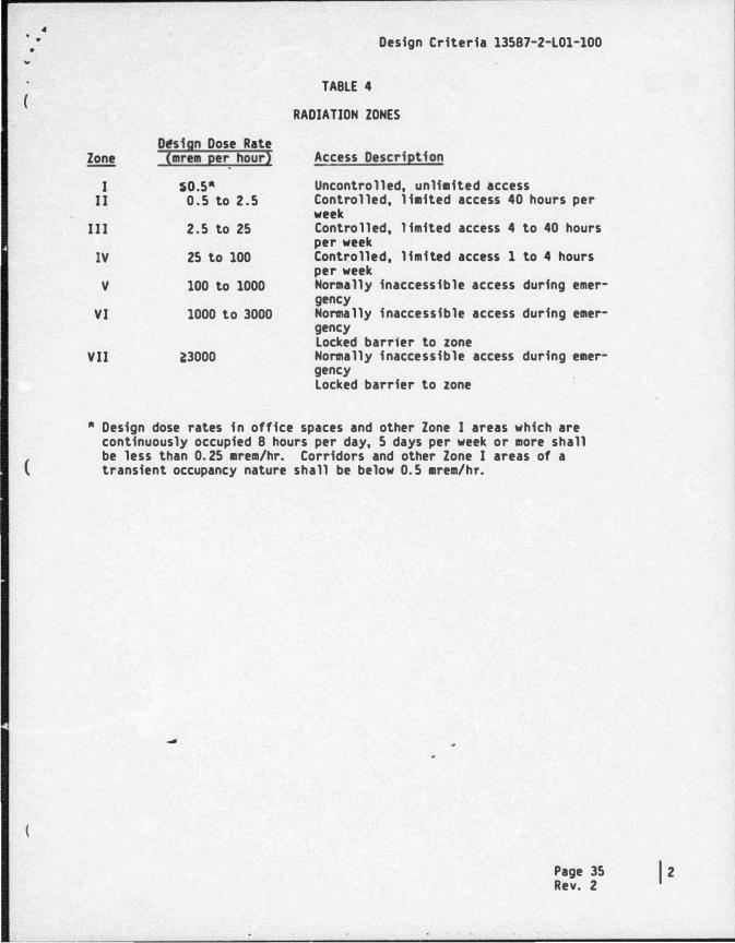
Dtsign Dose Rate Zone (mrem per_ hour)
I �o.5� I I 0 . 5 to 2 . 5
I I I 2 . 5 to 25
IV 25 to 100
v 100 to 1000
VI 1000 to 3000
VII �3000
Design Criteria 13587-2-l01-100
TABLE 4
RADIATION ZONES
Access Description
Uncontrolled, unlimited access Control led, l imited access 40 hours per week Controlled, l imited access 4 to 40 hours per week Controlled, l imited access 1 to 4 hours per week Normally inaccessible access during emergency Normally inaccessible access during emergency locked barrfer to zone Normally inaccessible access during emergency locked barrier to zone
� Design dose rates in office spaces and other Zone I areas which are continuously occupied 8 hours per day, 5 days per week or more shall be less than 0. 25 mrem/hr. Corridors and other Zone I areas of a transient occupancy nature shall be below 0. 5 mrem/hr.
-
Page 35 1 2 Rev. 2