Embed Size (px)
Citation preview

62TE Update Front Wheel Drive 6 Speed
Presented by: Mike Souza
ATRA Senior Research Technician

Welcome To Today’s Presentation
Sponsored By: 62TE Update Webinar ©2014 ATRA. All Rights Reserved.

Why Six-Speed? The 62TE transaxle offers distinct advantages over four-speed transaxles. Providing additional ratios offers quicker acceleration due to shorter shift intervals and the ability to maintain an engine’s optimal RPM range, providing the highest efficiency. This translates into increased fuel economy.

∗ The 62TE is the new generation of FWD/AWD Transaxles in production for Dodge/Chrysler. The concept has been around for many years but has been introduced in the 2007 Model Year.
∗ These models include: “JS” Seabring, Seabring Convertible, and Avenger with the 3.5L V6 “CS” Pacifica with the 4.0L V6.
∗ The concept was to take a proven reliable 41TE (4 speed) and split the transfer/pinion drive with an underdrive/direct clutch to drive a double ratio to the final drive.
∗ Although this is classified as a 6 speed fwd transaxle, there are 7 forward speeds due to the addition of a 4th gear prime ratio that is used during a 6-4 kickdown.
∗ This prevents a double swap of components allowing for a smooth kickdown.

The 62TE transaxle is identified by a bar code label (1) that is fixed to the transaxle or the “PK” number (2).
1. Traceability 2. Supplier Code 3. Component Code 4. Build Day (Julian Date) 5. Build Year 6. Line/Shift Code 7. Build Sequence 8. Last Three Part Number Digits 9. Revision Level 10. Transmission Part Number 11. Part Number Prefix
(1)
(2)
2

Input Shaft Speed Sensor (ISS)
Output Shaft Speed Sensor (OSS)
Transfer Shaft Speed Sensor (TSS)
ISS The ISS has been relocated to the top of the case, and like the 41TE, continues to read turbine speed from the input clutch hub. TSS The 40/41TE OSS has been relocated to the rear of the case (backside) and renamed the TSS. It continues to read rotation of the front annulus/rear carrier assembly. OSS The OSS is located at the rear of the case and is unique to the 62TE. It reads the rotation of the underdrive compounder output carrier.
62TE Three Speed Sensors
Crank Sensor
The are two different metals used to control and signal the module both solenoid command and circuit monitors. Pressure Switches are GOLD pins and Solenoids are TIN pins
62TE Case Connector

62TE Pressure Switch Status

• RFE-style solenoid/pressure switch assembly with 23-way connector • Electronically Modulated Converter Clutch (EMCC) Variable Force • Solenoid (VFS) • Line Pressure (LP) VFS • Line Pressure sensor • Transaxle Range Sensor (TRS)
Other Changes from the 41TE to the 62TE
TCC solenoid (EMCC) VFS
Line Pressure Sensor (Transducer)
RFE Style Solenoid Pressure Switch Assembly
Line Pressure (LP) VFS
Transaxle Range Sensor (TRS)

• Low clutch switch valve • New blocker valve (Direct Clutch Switch)
Prevents simultaneous application of the DC and LC
Manual Valve
Blocker Valve (Direct Clutch Switch)
L/R Switch Valve
Solenoid Switch Valve
TCC Switch Valve Low Clutch Switch Valve
TCC Control Valve
TCC Regulator Valve
Pressure Regulator Valve
#1 #2
Other Changes from the 41TE to the 62TE

The 62TE valve body has nine (9) check balls (used for plugs) and four used in the hydraulic shift control circuit:
The 9 check balls used for plugs are non removable.
Some valve bodies do not have the U/D check ball #2.
Other Changes from the 41TE to the 62TE

• Three additional oil transfer tubes which supply the UD compounder assembly
Other Changes from the 41TE to the 62TE

This 6 speed transaxle is basically a 41TE with some additional components referred to as the Underdrive (UD) Compounder Assembly.
Underdrive (UD) Compounder Assembly: • Low Clutch (LC) • Direct Clutch (DC) • Overrunning Clutch (ORC) • Planetary gear set
41TE
62TE

The underdrive compounder assembly has two modes of operation: Direct and Reduction.
The 2-3, 3-2, and 4-2 shifts require a “Double Swap” shift. This occurs when two elements are turned off while two different elements are engaged.
The clutch-to-clutch synchronization takes place within 40 – 70 milliseconds, producing a smooth shift. If the underdrive compounder assembly shifts too early (in relation to the shifts taking place in the main centerline), a shudder or harsh shift results.
If the underdrive assembly shifts to late, the driver experiences a “Double Bump” sensation.
To avoid a double swap shift in a 6-4 downshift, the transaxle shifts into 4th prime, which requires the deactivation of the OD clutch and the simultaneous application of the UD clutch.

A freewheel (sprag) is used to provide this nonsynchronous clutch apply and release sequence.
The sprag holds in first, third and fourth providing a smoother 1-2, 2-1, 4-5 and 5-4 shift.
• A = Applied • H = Holding • * = Limp-in Mode • ^ = Applied in coast only P = Prime
P
Same Ratios carried over from the 41TE

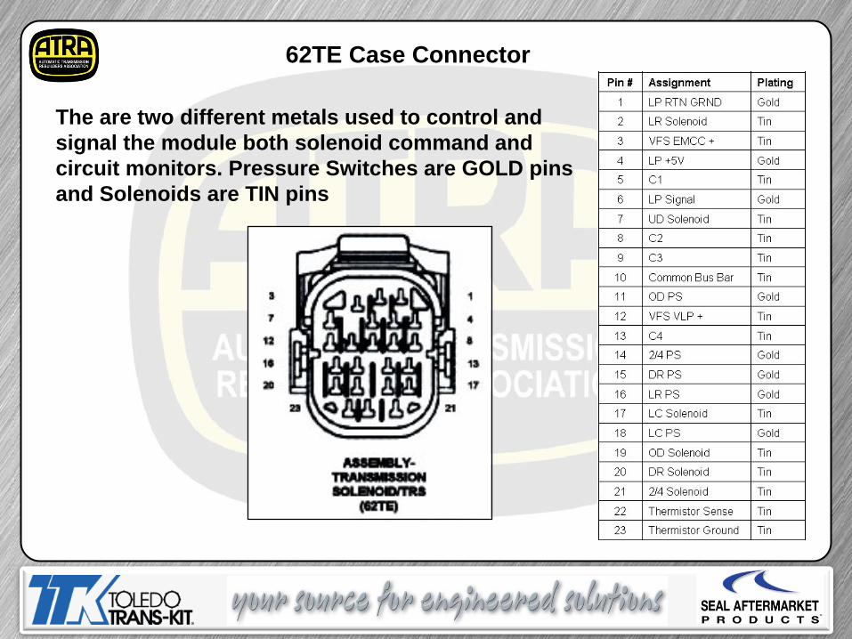
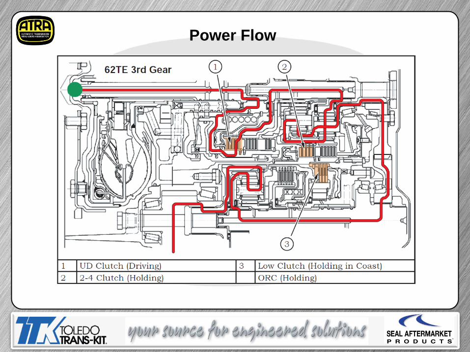
Power Flow

Power Flow
Power Flow
Power Flow

Power Flow

Power Flow

Power Flow

Power Flow

Compounder Assembly Removal
Remove the valve body & feed tubes before removing compounder assembly
Remove snap ring (no need to remove all the bolts)

Compounder Assembly Removal The O.E. tool or similar makes removal of the Compounder Assembly a much easier job.
Miller Tool #9908
Only remove bolts needed to install tool
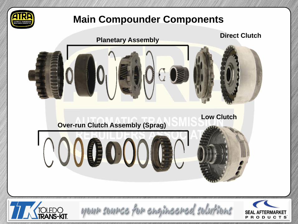
Main Compounder Components
Direct Clutch
Low Clutch Over-run Clutch Assembly (Sprag)
Planetary Assembly

Component Disassembly
There is an Adjustable Shim between the Sun Gear & Planet.
Remove the Planetary Gear set.

Component Disassembly
Using two small picks or scribes remove the Retainer Clip
3 Tabs

Component Disassembly
Check the “Split” Roller Bearing for wear or damage
Then Remove the Direct Clutch assembly.
Using two small picks or scribes remove the
Split Bearing

1: Remove Tapered Snap ring 2: Remove Selectable Plate 3: Remove #1 thrust bearing, hub, and #2 thrust bearing 4: Remove single sided frictions 5: Compress Balance piston with tool #8250 and remove snap ring 6: Remove Piston ASSEMBLE (Reverse Procedure)
Direct Clutch Disassembly – Reassembly
Miller # 9727 piston installation tool

Measure clutch clearance using 30 psi of air pressure through
compounder feed hole. Clearance is 0.037” to 0.056”
Measure with clutch hub removed
Direct Clutch Endplay

1: Remove Transfer Shaft 2: Remove Sprag, Snap Ring, Reaction Plate and Clutch Plates 3: Remove Clutches and Steels 4: Compress Return spring with tool #9725 5: Remove Piston
ASSEMBLE (Reverse Procedure)
Low Clutch Disassembly – Reassembly
Miller Tool 9725

Clearance is: 0.048-0.76mm (.018-.029 in)
Low Clutch Endplay
Measure clutch clearance using 30 psi of air pressure through compounder feed hole.

Underdrive “One-Way Clutch”
The inner race has offset splines, the outer race has the ID groove (faces down when installed correctly). The outer race should rotate counter clockwise when all is together correctly.
Held
Turn
ID Groove

Scarf Cut Sealing Rings
Check the Scarf Cut Sealing Rings for wear and damage. Replace as needed.

Common Problem
Direct Clutch Piston De-lamination (split rubber seal). Some pistons with minimal damage may air check well.

Torque Converter
The 62TE Torque Converter is what they call as “Squished Design”. This change had to happen do to space availability.
62TE 41TE

Torque Converter

62TE Front Pump
The 62TE Front Pump is also called “squished design” do to the limited space. Side by side the changes are obvious.
62TE 41TE

62TE Front Pump Assembly
When assembling the front pump it is important to note that the pump gears now have assemble dots. These dots must face up when assembling.
The side of the gears with the greater chamfer on the end of the teeth goes into the pump pocket first (facing down).
62TE 41TE

Face to gear clearance is 0.0008 – 0.0018 in. Check with plastic gauge!
Outer gear and pocket 0.0079 – 0.0035 in. Outer gear and crescent 0.0023 – 0.0035 in. Inner gear and crescent 0.0036 – 0.0151 in.
62TE Front Pump Assembly

Cooler Bypass Valve
The cooler bypass valve is a high risk area. It is a good idea to replace the valve with a NEW VALVE when doing a repair on the transmission.

Most Common Failure
Low Clutch Sealing Ring Grooves
Sealing Ring Grooves

Most common failure Ring Land Wear
Underdrive Compounder
Low Clutch Drum
Approx. 0.005” Clearance
Normal

Badly Worn
Most common failure Ring Land Wear
Underdrive Compounder
Low Clutch Drum

Extreme Wear
Most common failure Ring Land Wear
Underdrive Compounder
Low Clutch Drum
100% Failure Rate
Available in aftermarket with steel
insert
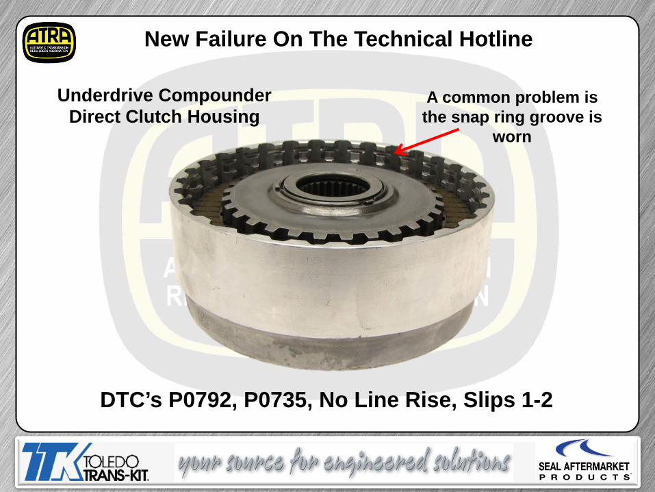
A common problem is the snap ring groove is
worn
DTC’s P0792, P0735, No Line Rise, Slips 1-2
Underdrive Compounder Direct Clutch Housing
New Failure On The Technical Hotline

Most Common Code DTC P2764, TCC Stuck “ON”
Replace the TCC solenoid
Part #5169313AA.
Line Pressure Transducer
Solenoid Block
Line Pressure Solenoid

Most Common Builder Error
Correct
If the seal is installed upside down it will block the 2/4 clutch circuit and result in a loss of 3rd in limp mode, 4th or 6th. Install the seal with the slot facing up as shown.
“First Time Builder Error”

Today’s Presentation Sponsored By:
Thank You For Attending 62TE Update Webinar ©2014 ATRA. All Rights Reserved.