Embed Size (px)
Citation preview

LCC7 SPECIAL TOPIC REPORT
Operational Issues and Practices

O P E R A T I O N A L I S S U E S A N D P R A C T I C E S
© December 2011
Advanced Nuclear Technology International
Analysvägen 5, SE-435 33 Mölnlycke
Sweden
www.antinternational.com
Operational Issues and Practices
Authors
Francis Nordmann Beauchamp, France
Dewey Rochester Charlotte, NC, USA
Jan Kysela Rez, Czech Republic
Suat Odar Erlangen, Germany
Technical Editor
Francis Nordmann Beauchamp, France

O P E R A T I O N A L I S S U E S A N D P R A C T I C E S
Copyright © Advanced Nuclear Technology International Europe AB, ANT International, 2011.
I(III)
Disclaimer
The information presented in this report has been compiled and analysed by
Advanced Nuclear Technology International Europe AB (ANT International®)
and its subcontractors. ANT International has exercised due diligence in this work,
but does not warrant the accuracy or completeness of the information.
ANT International does not assume any responsibility for any consequences
as a result of the use of the information for any party, except a warranty
for reasonable technical skill, which is limited to the amount paid for this assignment
by each LCC programme member.
O P E R A T I O N A L I S S U E S A N D P R A C T I C E S
Copyright © Advanced Nuclear Technology International Europe AB, ANT International, 2011.
II(III)
Contents
1 Introduction (Francis Nordmann) 1-1
2 Total Organic Carbon (TOC) in primary and secondary system water 2-1
2.1 Introduction (Francis Nordmann) 2-1 2.2 Background information (Jan Kysela) 2-1 2.3 Analytical systems and equipment for TOC (Jan Kysela) 2-2 2.4 Source of the carbon in RCS (Jan Kysela) 2-4 2.5 Source of TOC in makeup water – Elimination methods
(Francis Nordmann) 2-17 2.6 Potential consequences of TOC in RCS and secondary system. TOC
guidelines and existing limit of water chemistry specification (Francis Nordmann) 2-21
2.7 Summary and recommendation (Francis Nordmann) 2-23
3 Best practices for corrosion products removal in RCSs of VVER and the use of mechanical filters or macroporous resins 3-1
3.1 Introduction (Jan Kysela) 3-1 3.2 High temperature mechanical filtration in VVER (Jan Kysela) 3-1 3.2.1 Filtration process 3-1 3.2.2 Mechanism of filtration at HT, particles removal 3-4 3.2.3 Effectiveness of the filtration 3-6 3.2.4 Regeneration, backwashing, drop pressure behaviour during cycle 3-12 3.2.5 Activity removal, filtration particles investigation 3-14 3.2.6 HTF operation results at VVER units 3-16 3.3 Corrosion products removal in VVER by mechanical filtration when
reactor is stopped after shutdown and fuel is out from core (Jan Kysela) 3-18 3.4 Use of macroporous resins in NPP for corrosion products removal in PWR
(Dewey Rochester) 3-20 3.5 Specifications of macroporous resins (Dewey Rochester) 3-23
4 Best practices for the use of IER for RCS, SGBD, and the Spent Fuel Pool (SFP) 4-1
4.1 Introduction (Francis Nordmann) 4-1 4.2 RCS IER strategy and practices (Dewey Rochester) 4-1 4.3 Spent Fuel Pool IER (Dewey Rochester) 4-4 4.4 SGBD (Francis Nordmann) 4-5 4.4.1 SGBD design and flow rate 4-5 4.4.2 SGBD regeneration and design 4-6 4.4.3 SGBD regeneration and treatment selection 4-8 4.4.4 System design – Resin beds options -Saturated resins 4-11 4.4.5 Alternate purification systems 4-16 4.4.6 Rationale for options selections 4-18 4.5 IER specifications (Dewey Rochester) 4-20 4.5.1 Industry resin specification overview (U.S.) 4-20 4.5.2 Comparison of resin specifications from U.S. utilities 4-21
5 Best practices to mitigate condenser leakages and recommendations for Operation procedures in case of large impurities ingress 5-1
5.1 Introduction (Francis Nordmann) 5-1 5.2 German practices to monitor and repair condenser leaks (Suat Odar) 5-1 5.2.1 Condenser Leak Monitoring 5-1 5.2.2 Defect condenser tube location and repair 5-4
O P E R A T I O N A L I S S U E S A N D P R A C T I C E S
Copyright © Advanced Nuclear Technology International Europe AB, ANT International, 2011.
III(III)
5.3 Strategy to apply in case of condenser leakages, including large ingress (Francis Nordmann) 5-6
5.3.1 Influence of the cooling water characteristics 5-6 5.3.2 Influence of the leak rate and the SG materials 5-10 5.3.3 Influence of condenser design 5-11 5.3.4 Reaction in case of large leak 5-12 5.3.4.1 Large fresh water leak 5-13 5.3.4.2 Large seawater leak 5-14 5.3.5 Strategy for air ingress 5-16 5.3.6 Strategy for decision 5-16
6 The use of dispersant to mitigate SG corrosion product deposition (Dewey Rochester) 6-1
6.1 Introduction 6-1 6.2 Plant evaluation 6-1 6.2.1 System design components - Identification of materials 6-1 6.2.2 FW iron concentration - Composite sampling 6-5 6.2.3 Cost benefit analysis 6-6 6.2.4 Environmental considerations 6-7 6.2.5 Selection of injection location and equipment 6-8 6.3 Application of dispersant 6-11 6.3.1 Plant procedures 6-13 6.3.1.1 Initial application 6-13 6.3.1.2 Recommendations to prevent over feeding 6-14 6.3.2 Sampling and analysis 6-15 6.3.2.1 Corrosion product measurements 6-15 6.3.2.2 Monitoring of chemical species 6-15 6.3.3 Potential impact on plant parameters 6-16 6.4 Field experience in U.S. 6-18 6.4.1 Information from ANO-1 Unit 2 short term trial 6-18 6.4.2 Results of the long term trial at McGuire NPS 6-19 6.5 Conclusion and recommendation (Francis Nordmann) 6-22
7 References 7-1
Nomenclature
Unit conversion

O P E R A T I O N A L I S S U E S A N D P R A C T I C E S
Copyright © Advanced Nuclear Technology International Europe AB, ANT International, 2011.
1-1(1-1)=
1 Introduction (Francis Nordmann) This report gathers various types of information directly related to operation of Nuclear Power Plants (NPP) of any type. Some Sections may particularly concern specific types of reactors, as it is obviously the case for SGBD purification which exists in Pressurized Water Reactor (PWR) and Voda Voda Energo Reactor (Russian Acronym for the Russian type of PWR) (VVER) but not in Boiling Water Reactor (BWR) units.
The report contents have been selected based upon the input from the LCC16 customers at the last seminars (LCC6 in 2011).
The purpose of this report is to:
Describe the issues associated with the various topics covered in the report;
Propose some of the best practices for operating the NPP with the best compromise in term of safety, long term material behaviour, economic and environmental impact, practical implementation, feasibility and reliability of the practices;
Give recommendations based on the above concerns.
It must be acknowledged that the various practices described and recommended are only examples based on some experts and utilities experience and should not be considered as a mandatory practice or even as a guideline.
This information of this report is provided to:
Help Utilities at evaluating their own practices and considering potential improvements;
Give information to Manufacturers on the impact of their design selection on plant operation and in some cases to help them to include operational issues when selecting design options;
Assist Regulators at evaluating utilities practices and performances.
1 LWR Coolant Chemistry

O P E R A T I O N A L I S S U E S A N D P R A C T I C E S
Copyright © Advanced Nuclear Technology International Europe AB, ANT International, 2011.
2-1(2-24)=
2 Total Organic Carbon (TOC) in primary and secondary system water
2.1 Introduction (Francis Nordmann) The TOC content may be a controversial subject for several reasons. In BWR, TOC with chloride containing compounds may influence conductivity and induce the presence of free chlorides into the coolant with the associated risk of Stress Corrosion Cracking (SCC). In PWR/VVER, organic compounds may come from Ion Exchange Resins (IER), demineralised make up water, amine treatment, maintenance activities, previous decontamination, and oil.
TOC is a combination of various types of organic compounds from various origins;
TOC is not always monitored and is not easily measured but may affect Cation Conductivity (CC) and its sensitivity to detect other impurities;
It is not easy to eliminate TOC, particularly through the typical purification means such as Ion Exchange Resin (IER) and Filters. Removal depends on the type of compounds that are present. However, the presence of organic compounds is not as deleterious as many other elements such as chlorides;
TOC may be an indicator of other contamination and may be harmful, particularly in presence of other impurities; TOC may also decompose under high temperature in primary or secondary system resulting in other undesirable elements;
TOC may influence the layer of crud deposition on fuel surface or of deposits on Steam Generator (SG) tubes.
This Section will be helpful for chemists evaluating the potential sources and associated consequences of TOC in the primary and secondary systems and for preparing water chemistry specifications. It will also be helpful for manufacturers at better understanding the risks associated with the presence of TOC on their respective components and for regulators to evaluate the safety issues of TOC. Monitoring in the Reactor Coolant System (RCS) is addressed for the specific case of VVERs, where the TOC may also come from oil.
2.2 Background information (Jan Kysela) Present praxis of PWR/VVER and BWR shows that the cycle chemistry in the majority of NPP is capable of keeping the organic level within acceptable levels. There are differences in management of TOC concerning guidelines recommendation and analytical system used between PWR/VVER on one side and BWR on the other side and also between the same type of power plants (e.g. PWR or VVER). At BWR reactors, the main interest is concerning TOC with chloride containing compounds that may influence conductivity that is the main parameter representing quality of coolant and that my induce SCC of stainless steel. PWR/VVER make up water, resin intrusion into primary circuit, waste from decontamination solutions, the use of amines and other organic impurities (e.g. from oil and grease) are the main driving forces to manage TOC content.
For the fossil plants the determination of organic compounds has been historically done. In comparison with NPP, coal fired plants have the possibility of TOC self-cleaning (destruction) by hydrolysis/thermolysis. This is partially true in nuclear systems operating with low superheat.

O P E R A T I O N A L I S S U E S A N D P R A C T I C E S
Copyright © Advanced Nuclear Technology International Europe AB, ANT International, 2011.
2-2(2-24)=
Fossil plant experiences with TOC provide examples of experience with long term study and investigation of organics behaviour. This is true mainly for makeup water and condensate treatment because these systems are the main sources of organics in direct cycle coal fired plant. In PWR/VVER there are other possibilities where organics can enter the primary coolant, like resins intrusion, organic impurities from reactor pool water and decontamination. So far, limited experience and knowledge exist in PWR/VVER organics matter issues. Some manufacturers consider them as deleterious compounds for corrosion of specific components. However, there are hardly any examples of degradation coming from the sole presence of TOC (without associated species such as chlorides, sulphur).
2.3 Analytical systems and equipment for TOC (Jan Kysela)
The main demand for modern fossil units and NPP is to achieve the highest quality of water in coolant circuits. While the behaviour of inorganic compounds in water coolant systems is known, the knowledge of organics (TOC) is still partially missing. Besides soluble carbon dioxide, it is important to know the oxidation and decomposition process of large organic molecules which breakdowns into small molecules, organic acids etc. Understanding of these processes and knowing the final products of oxidation needs analytical system for TOC measurement, that gives fast and reliable information.
The determination of organic compounds has been based on a procedure using Chemical Oxygen Demands (COD), manganese and later Dichromate Oxygen Consumed standard method. Recent progress in the field has led to the knowledge that these methods can produce only no-selective partial oxidation with an insufficient detection limit [Jiricek, 2000].
The need for more precise determination of even trace concentrations of dissolved organic material throughout the steam/water cycle has resulted in the fast application of methods based on selective determination of oxidation products rather than oxidation consumption. With the existence of fast and precise analytical methods, the determination of the TOC, is more and more applied to NPP, even though organic contamination is generally considered of less important than inorganic impurities. Continuous on line TOC analyzers with membrane conductivity are the preferred choice for critical application in NPP.
All TOC measurement systems work on the same principle: partial or full oxidation of carbon dioxide that is then detected by different physical methods. The TOC instrument measures the amount of Total Carbon (TC), Inorganic Carbon (IC) and TOC in water. The key point about a TOC analyzer is whether it can efficiently oxidize and decompose all insoluble and macromolecular organic compounds, not just the easily decomposed, low molecular weight compounds. The 680 °C combustion catalytic oxidation method can efficiently analyse all organic compounds.
Organics are often divided and defined as the following:
soluble/Dissolved Organic Carbon (DOC),
Non purgeable Organic Carbon (NPOC),
Purgeable Organic Carbon (POC) and,
Volatile Organic Carbon (VOC).
There is also IC in form of dissolved CO2 (DCO2), hydrogen carbonate (HCO3-) and carbonate
(CO32-) that can result in carbon dioxide production.

O P E R A T I O N A L I S S U E S A N D P R A C T I C E S
Copyright © Advanced Nuclear Technology International Europe AB, ANT International, 2011.
2-3(2-24)=
Carbon in water can be in organic or inorganic form. Only discussed here is the organic form of the carbon; the IC has to be removed before organic carbon determination. For determination of TOC, different methods of oxidation are used:
thermal oxidation at higher temperature,
chemical oxidation,
Ultraviolet (UV) radiation,
combination of chemical oxidation and UV radiation.
When TOC is oxidized, released carbon oxide is measured and TOC value is calculated.
Analytical systems and equipment for TOC (total organic) and TC measurement are described by Shimadzu Company [Shimadzu, 2011]. Below are a few examples of different organic species measurements.
NPOC Measurement (TOC by acidification/sparging method)
A small amount of hydrochloric acid is added to acidify the sample, which is sparged with spurge gas. This converts all IC in the sample into carbon dioxide and drives the CO2 out of the sample solution. The TOC concentration is determined by measuring the TC of the sample after the IC is eliminated. NPOC measurement is equivalent to TOC measurement using acidification and sparging (IC elimination) defined for official test methods (Environmental Protection Agency in the USA (EPA), American Society for Testing and Materials Standards (ASTM), European Norm (EN), etc.). As any purgeable organic compounds may be lost from the sample during sparging, the TOC measured by this method can be called NPOC.
POC measurement
POC measurement is the measurement of the TOC of the organic carbon driven from the sample by the spurge gas in the sparging process during NPOC measurement. The CO2 component in the spurge gas is eliminated when the spurge gas passes through the CO2 absorber. The POC is then oxidized in the POC combustion tube to create carbon dioxide, which is detected by the Non Dispersive Infrared Detector (NDIR). This data is processed in the same way as in TC measurement
TOC (NPOC + POC) measurement
The TOC concentration is obtained by adding the POC to the NPOC concentration.

O P E R A T I O N A L I S S U E S A N D P R A C T I C E S
Copyright © Advanced Nuclear Technology International Europe AB, ANT International, 2011.
2-4(2-24)=
Figure 2-1: Flow diagram of the TOC instrument with oxidation furnace and NDIR.
Figure 2-2: Flow diagram of the TOC instrument with oxidation reactor (UV illumination and heating) and NDIR.
2.4 Source of the carbon in RCS (Jan Kysela) Organic compounds in PWR/VVER and BWR systems can be divided depending on the parts where the source of the carbon can be found. While in BWR systems organics source and circuits contamination is similar to fossil plants (condensate polisher outlet, makeup water). In PWR/VVER organics enter the RCS not only from makeup water but also through other systems, IER, amine treatment, maintenance activities, previous decontamination, and oil.

O P E R A T I O N A L I S S U E S A N D P R A C T I C E S
Copyright © Advanced Nuclear Technology International Europe AB, ANT International, 2011.
2-5(2-24)=
Condensate and makeup water
Organics in condensate polisher (when such system is present) outlet and make up water is one of the important parts that can enter RCS. A comprehensive survey study was performed primary to address potential sources, behaviour, and fate of organic compounds in Czech fossil and NPPs [Jiricek, 2000]. Recommendations drawn out from this survey dealt with sampling optimization (proper sampling points, sampling intervals) and the choice of proper equipment. The following sampling points have been chosen in the survey:
Coal-fired plants and VVER:
condensate from hot well
condensate after polisher
makeup water
blow down
treated radwaste water
primary circuit water (RCS)
The results comparing data from the most important samples of makeup water and polished condensate are shown in Figure 2-3.
Figure 2-3. TOC in water samples from individual power plants.
The data in Figure 2-3 show, with only one exception, that condensate samples have less organic carbon compared to make water samples. This indicates that both cycles are self-cleaning by thermal degradation of organics and that condensate polishers are efficient in the elimination of degradation products.
These data can be also evaluated from the point of view of limit values. Various sources recommend different limit values for TOC in condensate. The limits range from to 0.05 mg/kg (or ppm2) for turbine manufactures to 0.2 mg/kg for large organisations (VGB3, EPRI). The limit of 0.2 mg/kg seems to be a more realistic approach to organic level in the water/steam system. These limits will be compared later with limits for RCS, mainly driven by nuclear fuel vendors.
2 Parts per million (mg/kg) 3 Vereinigung der Grosskraftwerksbetreiber (Association of big Power Producers, Germany)

O P E R A T I O N A L I S S U E S A N D P R A C T I C E S
Copyright © Advanced Nuclear Technology International Europe AB, ANT International, 2011.
3-1(3-25)=
3 Best practices for corrosion products removal in RCSs of VVER and the use of mechanical filters or macroporous resins
3.1 Introduction (Jan Kysela) Corrosion products removal from RCS of PWR and VVER units is important for mitigating dose rates and radioactivity build up. This is achieved by IER and filters. Mechanical filtration of corrosion products in primary systems of nuclear power reactors is a useful tool to achieve high purity of the coolant and thus minimise possible crud deposition and corrosion products transport.
This Section covers corrosion products removal from RCS during shutdown with mechanical High Temperature Filtration (HTF). It also covers purification by mechanical filtration when reactor is stopped after shutdown and fuel is out from core. HTF is specifically used in VVER reactors to remove particulates from the system and is described in this Section.
This Section is of interest for improving corrosion products elimination, and will be particularly useful for Utilities and Manufacturers.
3.2 High temperature mechanical filtration in VVER (Jan Kysela)
The primary circuit of VVER-1000 reactors uses high-temperature filtration of primary circuit coolant to remove crud. Four filters are used, each with a filtration capacity of 100 t/h, one on each loop. HTF is performed to reduce primary circuit radiation fields resulting from activated crud deposition, to reduce radiation exposure of personnel, and to reduce the amount of decontamination work that may be required. According to information obtained from operations so far, the HTF system (designated as SV0-1 at Temelín NPP) has exhibited inconsistent results.
3.2.1 Filtration process
Right from the start of design work on the primary circuit of PWRs, designers toyed with the idea of HTF of coolant in order to eliminate crud. The interest for this system increased when increased duration of operation showed itself to significantly increase radiation fields, and thus exposure of operating staff. The goal of applying HTF was to stop growing radiation in existing units, and to achieve much lower radiation for new ones. For this reason, a lot of research on HTF has been performed during the 1970s. Work primarily focused on verifying the effectiveness of filters in eliminating crud. Because these were mostly electromagnetic filters, the main focus was on examining the dependency of filtration efficiency on crud particle size and on the magnetic properties of oxides – magnetite, nickel-ferrite, hematite, etc.
Tests of filter prototypes showed that it is possible to achieve an efficiency > 80%. The biggest problems were experienced during the application of this experience directly in the primary circuit, and especially the transfer of results to full-size filters. The main focus was on the question of how high the flow rate through the filter should be compared to the volume of the primary circuit. Numerical analyses showed that a flow rate of at least 1% of the entire flow rate of reactor coolant must be achieved, thus around 400-500 m3/h, in order to achieve a reduction of crud concentration in reactor coolant that would reduce the radiation field. Only in this case, the half-life of crud deposition would be comparable to the half-life of its removal from the coolant.
O P E R A T I O N A L I S S U E S A N D P R A C T I C E S
Copyright © Advanced Nuclear Technology International Europe AB, ANT International, 2011.
3-2(3-25)=
The second question was the ratio between dissolved and undissolved (dispersed) crud components in coolant, and the influence of these components on the transport of mass in the RCS, and thus also the activation rate. Today, the commonly accepted opinion is that the dominant mass transfer mechanism is crystallization and dissolution of crud on the surface, that is, of the soluble components of crud. All these questions concerning the influence of filtration of crud deposition in the RCS have be answered only once with demonstration tests directly performed on a nuclear unit with filtration of at least 400 t/h.
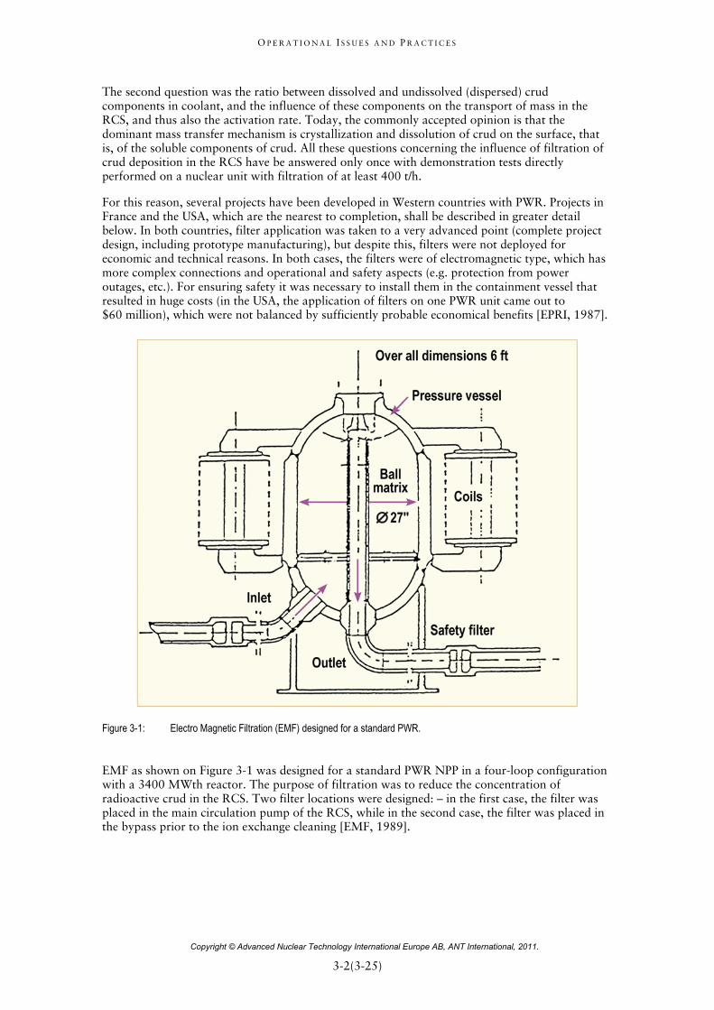
For this reason, several projects have been developed in Western countries with PWR. Projects in France and the USA, which are the nearest to completion, shall be described in greater detail below. In both countries, filter application was taken to a very advanced point (complete project design, including prototype manufacturing), but despite this, filters were not deployed for economic and technical reasons. In both cases, the filters were of electromagnetic type, which has more complex connections and operational and safety aspects (e.g. protection from power outages, etc.). For ensuring safety it was necessary to install them in the containment vessel that resulted in huge costs (in the USA, the application of filters on one PWR unit came out to $60 million), which were not balanced by sufficiently probable economical benefits [EPRI, 1987].
Figure 3-1: Electro Magnetic Filtration (EMF) designed for a standard PWR.
EMF as shown on Figure 3-1 was designed for a standard PWR NPP in a four-loop configuration with a 3400 MWth reactor. The purpose of filtration was to reduce the concentration of radioactive crud in the RCS. Two filter locations were designed: – in the first case, the filter was placed in the main circulation pump of the RCS, while in the second case, the filter was placed in the bypass prior to the ion exchange cleaning [EMF, 1989].
O P E R A T I O N A L I S S U E S A N D P R A C T I C E S
Copyright © Advanced Nuclear Technology International Europe AB, ANT International, 2011.
3-3(3-25)=
The following conclusions were reached based on performed analyses:
EMF with filtration of 0.5% of total flow in the RCS can reduce crud deposition by a factor of 2 to 5.
Based on conservative estimates, EMF can reduce personnel exposure by 160 man-rem.
With a cost of $10 000/man-rem and the reduction of 160 man-rem/year under consideration, the economic benefit (benefit-cost ratio) could be 6:1.
Placement of filters in the bypass prior to ion exchange cleaning was not shown to be of any advantage.
Installation costs for the entire system are $2.6 million.
Estimated savings due to EMF application, at a price of $10000/man-rem are $15 million.
Framatome (now Areva) Company developed an electromagnetic filter for cleaning RCS, and is offering it commercially for both PWR and BWR reactors [EMF, 1989]. The EMF system has the following characteristics:
EMF eliminates 85% of magnetite and nickel ferrites present in coolant at concentrations of 0.01to 1 mg/kg (ppm). It can eliminate particles of 1 μm in size and even smaller.
The filter (see Figure 3-1) is composed of a pressure vessel filled with beads magnetized by an electromagnetic coil.
Filter regeneration is performed in its hot state, which ensures perfect cleaning of the filler material and minimization of waste. Regeneration utilizes steam created directly inside the filter.
For some applications, the filter filler material can be regenerated with a reverse flush with aeration of the bead bed.
The question of cleaning RCS at full power parameters may also be addressed in other ways that are expected for VVER-1000 units, i.e. by using HTF with titanium sorbent. Japan's Mitsubishi Atomic Power Industries, Inc. has developed an inorganic high-temperature ceramic-based sorbent that can be operated under RCS conditions (320°C, 16 MPa) [Kitao et al, 1988]. The main reason why this sorbent was developed is reduction of dose rates from RCS equipment and reduction of radiation exposure of operating staff. More details on this sorbent, its properties and results of tests performed are listed in literature. As opposed to Ti sorbent, which captures the dispersion component of crud, the inorganic HTF acts selectively and primarily captures Co and Ni in dissolved (ionic) form.
Sorbent material is a Fe-Ti-O ceramic. The sorbent is manufactured in a form that is easy to pour into columns. The most common shape is a hollow cylinder 10 mm and 4 mm or 6 mm and 2 mm in diameter, and 5-10 mm high. High-temperature sorbent selectively adsorbs Co and Ni ions, which as Co-60 and Co-58 radionuclides are the dominant contributors to dose rates of RCS components. The sorbent's physical and mechanical properties were tested, as were its adsorptive capabilities, compatibility with the RCS environment, its possible further processing as radioactive waste, and it was tested in a high-pressure and high-temperature loop. Numerical analysis was used to evaluate the use of such a sorbent to possibly reduce dose rates from RCS equipment [Kitao et al, 1988]. Research shows that existing sorbents could be replaced by new ones based on titanium or zirconium oxides.

O P E R A T I O N A L I S S U E S A N D P R A C T I C E S
Copyright © Advanced Nuclear Technology International Europe AB, ANT International, 2011.
4-1(4-30)=
4 Best practices for the use of IER for RCS, SGBD, and the Spent Fuel Pool (SFP)
4.1 Introduction (Francis Nordmann) The use and selection of IER is very important since this has an impact on:
Impurities elimination such as sodium, chloride and other ions that may be deleterious for materials;
corrosion product elimination that may become activated in the RCS and;
radioactive element elimination from RCS for dose rate mitigation, which includes the specific case of some unusual highly radioactive elements that are not easily eliminated (e.g. Ag-110m).
The life time of IER depends on the chemical environment, the elements to be eliminated, the type and content of impurities, and the specified values at IER outlet. However, this life time does not only have an impact on the cost of resin replacement or on the resin regeneration frequency, which depends on the system and plant practices; it has also an important consequence on cost and environmental issues associated with the resins solid wastes and on the liquid effluents from regeneration. Consequently, the frequency of regeneration or replacement of IER should not be evaluated only though the time spent for this activity, but also according to the overall impact on the plant efficiency (i.e. purity at IER outlet, radioactivity elimination), the costs including waste disposal and the environmental consequences. Therefore, the initial cost of IER may not be the key point for their selection. The IER beds design as well as the operating mode, in addition to the treatment option in the case of the secondary system, must be carefully evaluated.
The best practices for the RCS and SFP purification are covered as well as the various approaches for SGBD. The increasing practice of operating the SGBD cation resins, once saturated with the alkaline reagent of the secondary system, is deeply discussed.
This Section is of interest for plant chemists and persons in charge of purchasing IER, manufacturers responsible for designing the purification systems according to utility purification specifications and for regulators in charge of understanding utilities practices and their efficiency.
4.2 RCS IER strategy and practices (Dewey Rochester) In Section 4.1, the elements for the selection and use of system IER are discussed. For the Primary system two additional aspects should be considered: optimizing the resin used to remove the radioactive and non-radioactive species of interest AND minimizing the amount of resin used. IER, especially the more species specific forms, are very expensive and the storage and/or disposal of highly radioactively contaminated resins pose significant challenges. Therefore, it is the role of the plant Chemistry and Engineering staffs to develop a strategy that not only efficiently removes the species of interest but minimizes the volume of spent resin generated.
PWRs usually have at least two Primary system demineralisers that can serve as either the in-service bed or as a spare for backup. These demineralisers are interchangeable, at least from an operational standpoint. Some plants have additional demineralisers usually charged with anion resin to be used to remove boron late in the cycle when the boron concentration is low and the feed and bleed method of removing boron produces excessive amounts of liquid radioactive waste. Occasionally, this third demineraliser is loaded with cation resin to remove lithium.
One strategy that meets the above criteria that has been used successfully in the U.S. for many cycles is described below.

O P E R A T I O N A L I S S U E S A N D P R A C T I C E S
Copyright © Advanced Nuclear Technology International Europe AB, ANT International, 2011.
4-2(4-30)=
Assume that for Cycle 1, the two Primary system demineralisers, labelled for convenience as ‘A’ and ‘B’, are loaded with a 1:1 mixture (by equivalents) of anion and cation resins. Neither bed has been saturated with lithium or equilibrated with the system beginning of cycle (BOC) boron concentration. Using the appropriate plant operating procedures, the ‘A’ demineraliser (arbitrary selection) is placed in service by equilibrating the resin with the system boron concentration. This can be done by either 1) flushing the demineraliser with primary system water until the effluent sample boron concentration is the same as the influent or, 2) diverting small amounts of coolant flow to the demineraliser and then to waste or recycle until the bed is saturated with boron. Once the demineraliser is saturated with boron at the system concentration, it can then be placed into service. However, caution should be exercised any time demineralisers are placed in service to avoid reactivity events due to any unexpected removal or addition of boron. Once in service, the demineraliser is now ready for the plant start-up.
After steady state power (100%) is reached, the next step is to add lithium to the primary system, again using plant procedures, to saturate the demineraliser with lithium to achieve the target primary system boron/lithium ratio (pHT). Once the demineraliser is saturated with lithium and the proper pHT is obtained, the main function of the demineraliser is to remove contaminants from the system. The ‘A’ demineraliser operates in this manner throughout the cycle. The ‘B’ demineraliser remains in the as charged condition during this period. Note: If there is ingress of contaminants or for any other reason the ‘B’ demineraliser has to be placed in service, this strategy may not be appropriate for the remaining of the cycle. Normally, feed and bleed operations during the cycle will generally maintain the target boron/lithium ratio. In some cases, the removal of lithium by other means is needed. In this case, the ‘B’ demineraliser (spare) may be used to remove lithium. It can be placed into operation for several minutes to remove the amount of lithium necessary to maintain the proper at temperature pH (pHT). As before great caution must be maintained since the anion resin in this demineraliser will remove boric acid so the effluent must either be sent to waste/recycle or blended with additional boric acid to maintain the proper system concentration before reinjected into the Primary system. Mass balance calculations can be made to determine exactly how long the ‘B’ demineraliser should be in service. The use of this demineraliser in this manner has a twofold advantage. First, it minimizes the amount of liquid radioactive waste generated by the feed and bleed method. Second, it begins to saturate the demineraliser using the lithium produced by the nuclear reaction of B-10 (10B(n,α)7Li). The ‘A’ demineraliser had to be initially saturated by frequent additions using the expensive highly enriched Li-7 to avoid excessive tritium build-up.
Just prior to shutdown (<24 hours) and before increasing the boron concentration to achieve the shutdown margin, the ‘A’ demineraliser should be removed from service and the ‘B’ demineraliser placed into operation. This also has two advantages. First, by removing ‘A’ from service, it can be placed in standby for several months thereby allowing the shorter lived radionuclides to decay, thus potentially reducing the radiation exposure to the personnel who sluice and dispose of the spent resin. Second, placing the ‘B’ demineraliser in service prior to achieving the boron shutdown margin, it can be saturated with boron so that it can safely be used during the next cycle while minimizing reactivity concerns.
The ‘B’ demineraliser is in service at the beginning of Cycle 2, while the ‘A’ demineraliser decays. Since the ‘B’ demineraliser has already been saturated to at or above the start-up boron concentration, it will equilibrate with the system boron concentration as boron is removed from the Primary system to achieve criticality. It is also saturated, or nearly so, compatible with the system lithium. The proper boron/lithium ratio to achieve the target pHT can be accomplished more quickly and with fewer lithium additions.
During the latter part of the cycle, the ‘A’ demineraliser is sluiced, recharged with MB resin and used for lithium and/or boron removal in a similar manner as the ‘B’ demineraliser was used during Cycle 1. The ‘B’ demineraliser is removed from service prior to the shutdown and the ‘A’ demineraliser placed back into operation before adding boron to achieve the shutdown margin. The ‘A’ demineraliser is used for the CBCU and the in service demineraliser for the next cycle.
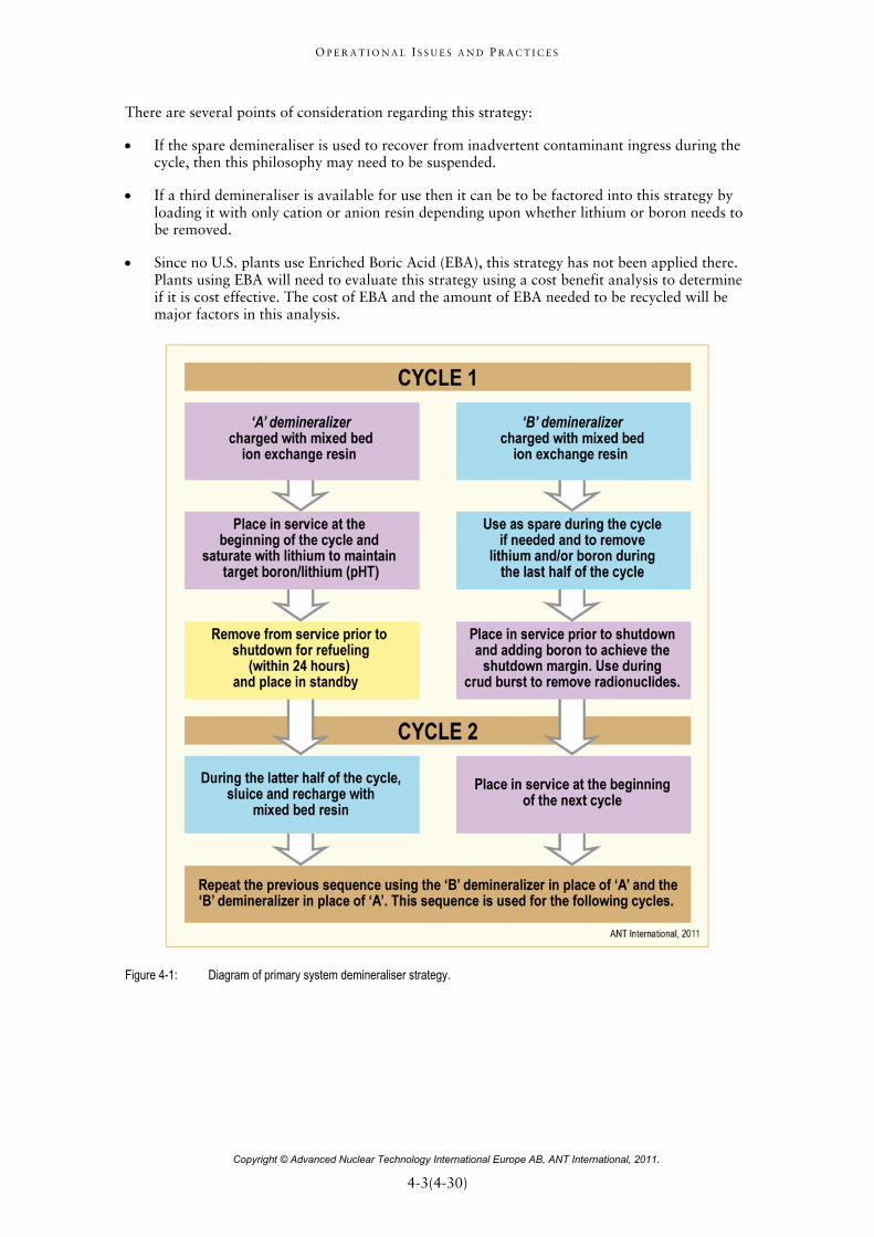
The above sequence is followed for future cycles. A graphic representation of this strategy is provided on Figure 4-1.
O P E R A T I O N A L I S S U E S A N D P R A C T I C E S
Copyright © Advanced Nuclear Technology International Europe AB, ANT International, 2011.
4-3(4-30)=
There are several points of consideration regarding this strategy:
If the spare demineraliser is used to recover from inadvertent contaminant ingress during the cycle, then this philosophy may need to be suspended.
If a third demineraliser is available for use then it can be to be factored into this strategy by loading it with only cation or anion resin depending upon whether lithium or boron needs to be removed.
Since no U.S. plants use Enriched Boric Acid (EBA), this strategy has not been applied there. Plants using EBA will need to evaluate this strategy using a cost benefit analysis to determine if it is cost effective. The cost of EBA and the amount of EBA needed to be recycled will be major factors in this analysis.
Figure 4-1: Diagram of primary system demineraliser strategy.
O P E R A T I O N A L I S S U E S A N D P R A C T I C E S
Copyright © Advanced Nuclear Technology International Europe AB, ANT International, 2011.
5-1(5-17)=
5 Best practices to mitigate condenser leakages and recommendations for Operation procedures in case of large impurities ingress
5.1 Introduction (Francis Nordmann) Historically, Condensate Polishing Stations (CPS) were used in many NPP to eliminate impurities from condenser leaks. Now, with the higher frequency of tight condensers (titanium tubing), there are less CPS than before but the need for a high purity FW remains. Moreover, in case of large sea water leaks, the presence of CPS is not able to ensure continued plant operation.
The practices to identify the presence of condenser leaks and to localize them in the affected part of the condenser have evolved and are described in this Section.
The various practices to plug the tubes with minimum impact on power production is covered in section 5.2, including the German practices to decrease the power only slightly.
A strategy is explained to develop a procedure, particularly in case of large impurities ingress, in order to take into account on-line monitoring (mainly CC and sodium and in some cases ion chromatography) versus grab samples (anions in some other cases).
The strategy to face a condenser leak depends on various parameters (cooling water type and the leak flow, condenser design, risk for the SG, etc.) which are detailed in section 5.3
This Section is of interest for plant chemists and Operators who are responsible for reacting rapidly to changing plant and chemistry conditions, for manufacturers in charge of condenser design and for regulators in charge of understanding utilities practices and their consequences on safety.
5.2 German practices to monitor and repair condenser leaks (Suat Odar)
For a quick, and adequate response to condenser leaks, it is necessary to use reliable leak monitoring system and experienced plant staff for the localization and repair of the defected tubes even with the small leak rates. In the following, the German practice that is explained, is based on the experience gained at Siemens-KWU designed PWR plants.
5.2.1 Condenser Leak Monitoring
The condenser leaks are recognized by SGBD sampling and Condenser sampling systems (see Figure 5-1). Between these two sampling locations, the SGBD sampling is the most sensitive one due to concentration of the impurities in the SG recirculating water. Accordingly, for small leak rates, the condenser leaks are detected first at the SGBD sampling, far before it can be recognized by Condenser sampling system. Large leak rates, can be quickly detected at the condenser level. However, the SGBD sampling does not indicate which condenser half or part (Hotwell (HW)) is leaking. This information is provided by Condenser HW Monitoring system, which is important for the repair work. The on-line monitoring equipment used at both sampling locations (SGBD and Condenser HW) is CC cell and sodium electrode. Even though different plants are using equipment with different design data from different vendors, the general technical data are in the same range as given in the following Table 5-1. The response time of this equipment depends on the sampling delay time. Therefore it is recommended to select sampling line lengths as short as possible. In the case of Siemens-KWU designed PWR plants the response time of the sampling locations SGBD and Condenser HW are in the range of 5-10 minutes and 1-2 minutes respectively.

O P E R A T I O N A L I S S U E S A N D P R A C T I C E S
Copyright © Advanced Nuclear Technology International Europe AB, ANT International, 2011.
5-2(5-17)=
Table 5-1: Technical information regarding CC cells and sodium electrodes used at Siemens-KWU designed PWR plants.
Technical information CC Sodium electrodes
Detection limit 0.01 µS/cm 0.02 µg/kg (ppb)
Detection sensitivity/Accuracy 0.01 – 0.02 µS/cm 0.01 – 0.02 µg/kg
Measurement range 0.01 – 10 µS/cm 0.01 – 100 µg/kg
Logarithmic scale 0.01 – 0.2 µS/cm has 50-60% of the total range
0.01 – 1 µg/kg has 50% of the total range
ANT International, 2011
The Condenser HW Sampling System for condenser leak monitoring consists of one CC cell for each HW-Half and one sodium electrode for all HW-Halves and for MSR-Reheated Steam Condensate (MSR-RSC) sampling as a reference (see Figure 5-1). Sodium electrode switches subsequently from one sampling location to another at each 10-15 minutes; whereas, the CC cells monitor on-line continuously each HW-Half. The reason for the selection of single sodium electrode was to avoid the influence of different electrodes that usually measure different values in the same sample due to their different characteristics. In this concept sodium electrode is used for the detection of very small leaks and the CC measurements are for the bigger leaks. Consequently, even though the absolute value of sodium is not 100 % accurate for small values, a small difference in sodium records between various sections of the condenser will be able to identify the failing one. The MSR-RSC sampling is selected for reference measurement, because this sampling has the lowest sodium concentration in the entire secondary circuit (less than in Make-up water).
Figure 5-1: Condenser leak-monitoring system used in new Siemens-KWU designed PWR plants, after [Zörner & Termuehlen, 1985.

O P E R A T I O N A L I S S U E S A N D P R A C T I C E S
Copyright © Advanced Nuclear Technology International Europe AB, ANT International, 2011.
5-3(5-17)=
Based on field experience this concept of using single sodium electrode for all HW-Halves was successful in providing reliable condenser leak monitoring. However, at two PWR plants, which have brackish/estuary river cooling water with the tide coming in and going out, this concept had to be changed to on-line continuous sodium measurements with sodium electrodes for each HW-Half. The reason was the continuous change in salt content of the estuary cooling water caused by the tide in and out (see Figure 5-2).
Figure 5-2: Condenser leak monitoring results at Brokdorf PWR plant as an example for an estuary cooling water with “tide coming in and going out” [Sauer, 2011].
O P E R A T I O N A L I S S U E S A N D P R A C T I C E S
Copyright © Advanced Nuclear Technology International Europe AB, ANT International, 2011.
6-1(6-24)=
6 The use of dispersant to mitigate SG corrosion product deposition (Dewey Rochester)
6.1 Introduction The mitigation of SG fouling and corrosion product deposition is an important responsibility of the plant chemist. Tube fouling can lead to corrosion and other operational issues such as a loss of heat transfer and main steam pressure. SG corrosion product deposition can result in TSP blockage, flow instability, and aggregation of lower tube sheet deposits. Corrosion products more easily induce the concentration of soluble impurities and thus corrosion risks. The use of dispersants in plants with high FW iron has the potential to delay SG cleaning, reduce the frequency of sludge lancing, and improve SG operation, safety and reliability.
This section is for those utility personnel who are involved in the planning and implementation of changes to the plant chemistry regime, and evaluating the options to mitigate SG fouling and corrosion product deposition. It will also assist regulators and manufacturers to better understand the issues related to the potential use of dispersant.
Corrosion products, which enter the SGs in the FW, can deposit within the SG and potentially cause several problems. These corrosion products consist mainly of iron and copper oxides. Deposition can cause tube and TSP fouling. Tube fouling can lead to a loss of heat transfer and a reduction in plant power output. TSP fouling, i.e., blocked flow holes, can result in SG level oscillations (sometimes called “chugging”) and to flow instability (flow-induced vibration). Corrosion product deposition can create crevices, which act as concentration sites, for FW impurities such as sodium, chlorides and sulphates and may cause corrosion within the SG to both the carbon steel internals and SG tubes. Any of these conditions can pose serious challenges for the NPP operator.
Over the years, several methods have been developed and used not only to reduce the amount of corrosion products transported to the SG and to remove the deposited corrosion products from the SG. Higher at-temperature condensate/FW (pHT) and better filtration techniques can also reduce the introduction of the corrosion products into the SG. Chemical cleaning and sludge lancing have been used to remove the corrosion product deposits. However, both of these procedures are time consuming, expensive and produce potentially radioactive and hazardous liquid wastes.
The use of dispersants, in this case Polyacrylic Acid (PAA), which can significantly inhibit the amount of corrosion product deposition, can be deployed as a different type of tool by plant Chemists to mitigate the effects of FW corrosion products. PAA may be a more cost effective and a simpler approach than the other techniques mentioned.
6.2 Plant evaluation
6.2.1 System design components - Identification of materials
PAA has been qualified in the U.S. for use in secondary side of recirculating SG by the Electric Power Research Institute (EPRI), [Fruzzetti, December 2007]. A key step in this qualification requires that the dispersants in concentrations at or above those expected during normal operation will not harm existing plant materials. This is done by performing laboratory tests on the components in question, reviewing previous operating experience with the same or similar materials, and applying engineering judgement to those materials that do not fall into one of the previous categories. EPRI has concluded that it is unlikely that there will be any significant increase in corrosion or degradation of materials in the secondary system, which will come in contact with PAA or its associated breakdown products [Fruzzetti, April 2009].
O P E R A T I O N A L I S S U E S A N D P R A C T I C E S
Copyright © Advanced Nuclear Technology International Europe AB, ANT International, 2011.
6-2(6-24)=
The steps for determining whether PAA is acceptable to use in a plant are:
1) Develop a list of the materials of construction for the secondary systems and components. These systems, components and materials include:
a) SG internals, including the tube material,
b) Condensate and FW systems, including heaters,
c) Steam systems and turbine,
d) Moisture separators and reheaters,
e) Condensate polisher resin (if used), blow down demineraliser resin (if used) and any associated filters, and
f) Elastomers, such as instrument internals.
2) Evaluate the above list with known corrosion mechanisms using existing data and information and applying engineering judgement for similar materials if no direct data are available.
a) SG tube degradation
b) FAC
c) Impact of PAA decomposition products
d) Changes in crevice pH
With respect to SG tube degradation, the following items should be addressed:
a) EC potential
b) Conductivity
c) Crevice pH
3) Develop a list of potential risks (if any), compensatory actions, and monitoring and contingency plans.
4) Write a safety evaluation and/or other documentation required by the licensees’ regulatory requirements. Included in these documents are the appropriate environmental impact assessment and approval, if required.
5) Perform a cost-benefit analysis to determine whether the application if economically justifiable. Alternatively, obtain approval from plant management using other criteria such as regulatory or political considerations.
Item #1 is a straightforward effort and can be handled by most plant Engineering staffs while Items #2 and #3 may require the assistance of an outside consultant or the NSSS vendor.
SG materials
The SG materials of construction can be divided into four groups:
Nickel alloy weld materials
Carbon steel and low alloy weld metals
Stainless steels
Carbon steel and low alloy steels

O P E R A T I O N A L I S S U E S A N D P R A C T I C E S
Copyright © Advanced Nuclear Technology International Europe AB, ANT International, 2011.
6-3(6-24)=
Results of testing and evaluations
Previous testing on Alloy 600 and Alloy 690 found these materials to be acceptable for PAA applications. For replacement recirculating SG, the crevices are not nearly as severe as compared to the original SG, so the concentration of detrimental species, such as sodium or chloride, is of lesser concern. Calculations performed using EPRI’s MULTEQ® indicate that no adverse impact on the at temperature pH (pHT) in the crevices is expected.
Carbon steel and low alloy steels
Materials SA-36 and A-569 were tested directly by McDermott Technologies. Materials similar to SA-508 Class 3 were tested directly by Atomic Energy Canada, Limited (AECL). SA-516 Grade 70 and SA-106 Grade B were present in the ANO-1 Unit 2 short term trial. The tests and evaluations indicated that the corrosion rates of these materials were acceptable in the presence of PAA concentrations expected in the SG during the McGuire Unit 2 long term trial [Marks, 2007].
Stainless steels
An evaluation of the tests performed on stainless steels (SA-335 P11) at PAA concentrations of 1 mg/l (ppm) showed an insignificant increase in the corrosion rate. This material was considered to bound SA-335 P22. Material 410S has not been tested but materials 405, 430 and 439 have been tested at 1 mg/l PAA. None of the tests found any corrosion issues in the presence of PAA [Marks, M-5508-00-42, Rev. 1, May 2007].
Weld metals
Nickel alloy welds have not been tested but due to the corrosion resistance of Alloys 600 and 690, these welds are not considered to be susceptible to corrosion.
For the McGuire trial, only one steel weld metal, F8P4-EF2-F2 submerged arc weld, was present in the SG. This material had not been tested; however, carbon steel materials, ER70S-6, a gas metal arc weld, had been tested in 1 mg/l PAA. The composition of the two weld metals were considered to be similar enough that there would be no corrosion issues with either weld.
Balance of plant materials
When considering the acceptability of PAA, the secondary side construction materials, several ways are used to perform this evaluation. First, any potential chemistry changes must be considered. Second, similar to the evaluations performed for the SG materials, the impact of PAA on these materials is necessary. Third, prior experience in fossil and nuclear plants is a valuable resource in these evaluations.
In order to determine acceptability of PAA on secondary system materials, a bounding estimate of the maximum PAA concentration is needed. For the qualification work performed by EPRI, the bounding concentration was selected to be 1 mg/kg (1 ppm). However, if other concentrations of PAA in the SGBD are used, the PAA feed rate can be calculated by the mass balance equation:
Eq. 6-1: Blowdown Blowdown PAAFeed PAAFeedM C M C
where
MBlowdown is the mass flow rate of the SGBD,
CBlowdown is the concentration of PAA in the blow down,
MPAAFeed is the mass flow of the PAA feed and,
CPAAFeed is the concentration of PAA in the feed tank.

O P E R A T I O N A L I S S U E S A N D P R A C T I C E S
Copyright © Advanced Nuclear Technology International Europe AB, ANT International, 2011.
7-1(7-3)=
7 References Alves-Vieira M., Nordmann F., Molé D. and Fourcroy H., Investigations on the Secondary Water
Treatment - pH Control and Compounds behaviour, EPRI, SGMP- TAG meeting. Santa Fe, NM, 5-7 December 2006.
Bengtsson B., Svanberg P., Bothin U., Svärd G. and Velin A., Experiences of Water treatment Applications at Ringhals, NPC’08 International Conference on Water Chemistry of Nuclear Reactor Systems – Berlin 14-18 September 2008.
Bengtsson B, Personal communication, Ringhals, Sweden, 23 March 2011.
Choi S. and Lumsden J., Investigation of Lead Equilibrium Lines on Pourbaix Diagram Using Electrochemical Measurements at 280°C, NPC’08 International Conference on Water Chemistry of Nuclear Reactor Systems – Berlin 14-18 September 2008.
Dauvois V., Lambert J., Desmoulins D. and Nordmann F., Laboratory and plant investigations on decomposition products of morpholine in the secondary system of French PWRs, Water chemistry of nuclear reactor systems 4, p. 369-374, BNES, London, 1986.
Dinov K. A., Primary Water Chemistry Experience and Radiation Field Control in Kozloduy NPP, JAIF International Conference on Water chemistry in NPP, Japan, Fukui City, April 1991.
Dobrovolska I. and Arkhypenko A., Water Chemical Treatment in Primary Circuit of WWER in Ukraine, Expert Meeting on Crud Deposition on Fuel in VVER Reactors, IAEA Technical meeting, Paks, Hungary, 2-5 July 2007.
Dobrovolska I., Corrosion products in primary circuits in Zaporozie power NPP, WANO Meeting “Monitoring of Activated Corrosion Products in Primary Circuit”, Temelin NPP, Czech Republic, 8-12 November 2010.
EdF, Ethanolamine Test at Saint-Alban NPP. Comparison with Morpholine, EdF - Energoatom workshop – June 1-2, 2004.
EMF, Preventing Harmful Deposition of Corrosion with EMF, Nucl. Eng. Int., August 1989.
EPRI, Study of Magnetic Filtration Applications to be Primary Secondary Systems of PWR Plants, EPRI, NP-514, May 1987.
Fruzzetti K., Varrin Kreider M. and Miller A., Dispersants for Tube Fouling Control, Volume 1: Qualification for a Short Term Trial at ANO-2, EPRI No. 1001422, March 2001.
Fruzzetti K., Dispersants for Tube Fouling Control, Volume 4: Long-Term Trial at McGuire Unit 2, EPRI No. 1015017, June 2007.
Fruzzetti K., Dispersants for Tube Fouling Control, Volume 5: PWR Dispersant Application Sourcebook, EPRI No. December 2007.
Fruzzetti K., EPRI Pressurized Water Reactor Secondary Water Chemistry Guidelines – Revision 7, 1016555, February 2009.
Galt K et al, Flexible Condensate Polishing Operation at Koeberg Nuclear Power Station, Water Chemistry of Nuclear reactor System 7, pages 385-392, BNES 1996.
Grezdo O. and Mraz V., Resin intrusion into the primary circuit of NPP Jaslovske Bohunice V-1, Symposium on VVER reactor physics and reactor safety, Znojmo 3-7, October 2005.
O P E R A T I O N A L I S S U E S A N D P R A C T I C E S
Copyright © Advanced Nuclear Technology International Europe AB, ANT International, 2011.
7-2(7-3)=
Grishakov A.V. at al., Experience in Development and use of Ultrasonic Plant for Cleaning the fuel Assemblies of VVER 440 Reactor Core, IAEA Technical Meeting on ‘Water Chemistry and Clad Corrosion/Deposition Including Fuel Failures, Kiev, Ukraine, 22-24 November 2010.
Hoffmann W. et al., Bestimmung von organischen Verunreinigungen in Leichtwasserreaktoren, VGB-Konferenz Chemie im Karftwerk, 1993.
Jiricek I., Power Plant Chemistry Journal, Edited by /www.ppchem, PPChem, 2(10), P 591-594, 2000.
Kitao H. et al, Development of High Temperature Absorbent in PWR Primary System, JAIF International Conference on Water Chemistry in NPP, p. 567-572, Tokyo, April 19-22, 1988.
Livingston D., Chemical composition of Rivers and Lakes. In (M. Fleischer ed.,) Data of Geochemistry, sixth edition, Chapter G. USGS Prof. Paper 440-G, page 64, 1963.
Luzanova L. M. and Zadonskij N. V., Atomnaja energia, V. 68N1, p. 52-54, January 1990.
Malac M., Activated Corrosion Products in Coolant, WANO Meeting “Monitoring of Activated Corrosion Products in Primary Circuit”, Temelin NPP, Czech Republic, 8-12 November 2010.
Marks, Dominion Engineering, EPRI, M-5508-00-42, Rev. 1, USA May 2007
Martykan M., Monitoring and Evaluation of Primary Water Chemistry and Radioation situation at Temelin NPP, WANO Meeting “Monitoring of Activated Corrosion Products in Primary Circuit”, Temelin NPP, Czech Republic, 8-12 November 2010.
Miller A., Kreider M., Varrin R. and Fruzzetti K., Dispersants for Tube Fouling Control: Volume 2: Short Term Trial at ANO-2, EPRI No. 10033144, September 2001.
Nashiem R., Davloor R., Harper W., Kim Smith K., Gauthier C. and Schexnailder S., Mitigation of Organically Bound Sulphate from water treatment plants at Bruce NGS and impact on Steam Generator secondary side chemistry control, Nuclear Plant Chemistry Conference, NPC 2010. Quebec, October 3-7, 2010.
Nordmann F., A computer code (MONA) for pH and chemistry evaluation in the secondary water of PWR, British Nuclear Energy Society Conference on Water chemistry of nuclear reactor systems 3. Bournemouth, UK. 17-21 October 1983. BNES, London 1983.
Odar S. and Nordmann F., PWR and VVER Secondary System Water Chemistry, Stand Alone Report, ANT International, Mölnlycke, Sweden, 2010.
Petrecky I., Chemistry water regimes at Dukovany NPP, IAEA Expert Meeting on Crud Deposition on Fuel in VVER Reactors, Rez, Czech Republic RI, 18-19 July 2005
Rühle W., “LLC3 –Annual Report”. ANT International meeting, Malta,, 2007.
Rühle W., Venz H., Nordmann F., Incoming Goods, Hazardous Materials and Aging of Plant Chemicals, Specific Topical Report, ANT International, Mölnlycke, Sweden, 2010.
Sauer H-R., Personal communication; courtesy of E-On, 2011.
Schunk J., Personal communications, 2011.
Simister C. et al., Journal of Radioanalytical and Nuclear Chemistry,
Shimadzu, Total Organic carbon Analyzer, Shimadzu Corporation, http//www.shimadzu.com, 2011.

O P E R A T I O N A L I S S U E S A N D P R A C T I C E S
Copyright © Advanced Nuclear Technology International Europe AB, ANT International, 2011.
7-3(7-3)=
Tung-Jen Wen and Chieh-Hsin Wang, Experiences on Reduction of Reactor Water Silica and Fresh Resin Leaching Organics for Kuo-Sheng Nuclear Power Plant, Nuclear Plant Chemistry Conference, NPC 2010. Quebec, October 3-7, 2010.
Turekian K. Oceans. Prentice-Hall, 1968.
Varga K. et al, Corrosion behaviour of stainless steel surfaces formed upon chemical decontamination, Electrochimica Acta, 46 (24), 3783-3790, 2001.
Varga K. et al., Comprehensive investigation of the corrosion state of the heat exchanger tubes of steam generators, Part I. General corrosion state and morphology, Journal of Nuclear Materials, 348 (1-2), 181-190, 2006.
Vonková K, Kysela J, Martykán M, Janešík J, Hanus V High-temperature filtration of primary circuit NPP Temelin experience (VVER – 1000) International Topical Meeting VVER 2007, Prague October 15-18, 2007.
Vonková, K. Kysela J., Martykán M., J. Janešík, V. HanusPrimary Water Chemistry and High Temperature Filtration System Experience at Temelín VVER 1000 NPP International conference on Water Chemistry of Nuclear Reactors Systems, September 2008, Berlin
Wilson J. and Bates J., Evaluation of High Cross Linked cation Gel Resins in a MPA Environment at Byron and Braidwood, International Conference Water Chemistry of Nuclear reactors Systems –EPRI - San Francisco October 11-14, 2004.
Yurmanov V. A., Dobrovolska I.,. Schelik Y., Operational Experience and Recent Improvements of High Temperature Filtration at WWER Plants International conference on Water Chemistry of Nuclear Reactors Systems, September 2008, Berlin
Yurmanov V et al, 2008
Yurmanov V., Private communications 2011.
Zadonskij N. V., Analiz progodnosti norm VCHR pervogo kontura, OAO TVEL, Moskva 2007.
Zmítko M. et al, Primary Water Chemistry and Radiation Field Experience at NPP Dukovany, Seminar on Primary and Secondary Side Water Chemistry of NPP, Balatonfured, 28 April – 3 May 1992.
Zörner W. and Termuehlen H., High integrity condensers for PWR power plants, ASME/IEEE Power Generation Conference, Milwaukee, Wisconsin, October 20-24, 1985.


![Francis Nordmann – CV · Francis Nordmann in: «Chambers Global Practice Guide: Real Estate» 2019 The Projects and Construction Review – Switzerland [Länderbericht Schweiz]](https://img.dokumen.tips/doc/110x75/5f0338a87e708231d40822f5/francis-nordmann-a-cv-francis-nordmann-in-chambers-global-practice-guide-real.jpg)