Embed Size (px)
Citation preview

ericssonz
LBI-38901E
Installation Manual
Orion™ Mobile Radio

2
TABLE OF CONTENTS
INTRODUCTION............................................................................ 3UNPACKING AND CHECKING EQUIPMENT............................. 3PLANNING THE INSTALLATION ................................................ 6EQUIPMENT REQUIRED.............................................................. 8INSTALLATION IN VEHICLES POWERED BY LIQUEFIED(LP) GAS......................................................................................... 9INSTALLATION ............................................................................. 9
RUNNING CABLES............................................................... 9Power Cable.................................................................... 12Accessory Cable.............................................................. 13Ignition Sense................................................................. 20Control Cable (Remote Mount Only).............................. 21
CONTROL UNIT MOUNTING (REMOTE APPLICATIONSONLY) ........................................................................... 21
SPEAKER D2LS1F............................................................... 26MICROPHONE HANGER AND/OR HOOKSWITCHMOUNTING ......................................................................... 26RADIO MOUNTING AND FINAL HOOK-UP..................... 27
Front Mount ................................................................... 27Remote Mount Installation.............................................. 29Cassette Mounting (EURO Only).................................... 30Cassette Assembly Mounting.......................................... 31
DUAL CONTROL UNITS............................................................. 34PREINSTALLATION PROGRAMMING PROCEDURE
-- FRONT MOUNT........................................................ 34PREINSTALLATION PROGRAMMING PROCEDURE
-- REMOTE MOUNT..................................................... 36INSTALLATION PROGRAMMING FOR FRONT MOUNT
DUAL CONTROL UNITS.............................................. 38INSTALLATION INSTRUCTIONS FOR REMOTE MOUNT
DUAL CONTROL UNITS.............................................. 39DUAL RADIO UNITS..................................................................... 43
This manual is published by Ericsson Inc., without any warranty. Improvements and changesto this manual necessitated by typographical errors, inaccuracies of current information, orimprovements to programs and/or equipment, may be made by Ericsson Inc., at any time andwithout notice. Such changes will be incorporated into new editions of this manual. No part ofthis manual may be reproduced or transmitted in any form or by any means, electronic ormechanical, including photocopying and recording, for any purpose, without the expresswritten permission of Ericsson Inc.
Copyright© October 1993 Ericsson GE Mobile Communications Inc.

3
INTRODUCTIONThis manual contains installation instructions for the Orion MobileRadio Unit and associated accessories. These instructions cover themounting and cabling of the radio; interconnection and wiring diagramsare provided for reference. Before installation the radio should beprogrammed using an IBM compatible personal computer and thefollowing items:
Serial/Flash Programming Interface Module TQ3370
Programming Cable TQ3377
EDACS Programming Software TQ3374
or
Conventional Programming Software TQ3367
IMPORTANT NOTICE
ORION UHF MOBILES
The PC programmer automatically defaults the receiver oscillator shiftto position No. 2. When field programming the receive frequencies forORION UHF mobiles, the oscillator shift must be programmed toposition No. 1 or No. 3. Enter the CONVENTIONAL and/orTRUNKED FREQUENCY SET screen of the PC programmer and setthe values in the “OS” column to “1” or “3”.
UNPACKING AND CHECKING EQUIPMENTCarefully unpack the radio and identify each item in the shippingcontainer as listed below. If damage has occurred to the equipmentduring shipment, file a claim with the carrier immediately. Theavailable options for the Orion Mobile Radio are covered in Table 1.
• Orion Mobile Radio Unit
• Microphone D2MC3W or D2MC3Z
• Speaker D2LS1F or D2LS1H
• Power Cable D2CE1V
• Fuse Kit D2PD1J
• Control Cable D2CE1Y

4
• Front Mount Bracket Kit D2MA3N
or
• Remote Mount Kit D2MA3R
with
• Control Unit Mount Kit D2MA3J
• Operator's Manual LBI-38888
• Installation Manual LBI-38901
Figure 1 - Orion Mobile Radio Components And Mounting Hardware
Figure 2 - Rear View Of Radios
USA EURO

5
Figure 3 - Cables

6
Table 1 - Orion Mobile Radio Optional AccessoriesOption Description Part Number
D2AN1M 900 MHz, 1/4 Wave Whip Antenna 19B801182P3D2AN1L 800 MHz 1/4 Wave Whip Antenna 19B209568P5D2AN1R VHF/UHF, 1/4 Wave Whip Antenna 19B209568P6D2CE1V Power Cable, 7.5 M 19B802622P1D2CE1W Accessory Cable, Front Mount 19B802554P1D2CE1X Accessory Cable, Rear Mount 19B802554P6D2CE1Y Control Cable, Remote Mount, 5.5 M 19B802554P3D2CE1Z Accessory Cable, Front Mount EURO 19B802554P11D2CE5R Extended Option Accessory Cable Front Mount 19B802554P2D2CE5S EXT Option Control Cable, Remote Mount, 5.5 M 19B802554P4D2CE5T EXT Option Accessory Cable, Remote Mount 19B802554P7D2CE5U EXT Option Accessory Cable, Front Mount, EURO 19B802554P12D2CE5V Control Cable, Remote Mount, EURO, 5.5 M 19B802554P13D2CE5W EXT Option Control Cable, Remote Mount, 5.5 M 19B802554P14D2CE5Z Dual Control Cable, Remote Mount, 9.0 M 19B802554P9D2CE7A Dual Radio Cable, Remote Mount, 2.0 M 19B802554P10D2CE7B Dual Control Cable, Remote Mount, 9.0 M, EUROD2CE7C Dual Radio Cable, Remote Mount, 2.0 M, EUROD2LS1F Speaker, GE Label 19A149590P1D2LS1H Speaker, ERICSSON Label 19A149590P11D2MA3J Mounting Bracket Kit, Remote Control Unit 344A4584G2D2MA3N Mounting Bracket Kit, Front Mount Radio 19B802672P1D2MA3R Mounting Bracket Kit, Remote Mount Radio 19B802673P1D2MA3W Mounting Bracket Kit, Remote Mount Radio, EURO 19B802672P1D2MA3X Cassette Mounting Bracket Kit, Front Mount, EURO 19B852366P1D2MC3W Microphone, GE LabelD2MC3Z Microphone, Ericsson LabelD2MK3E Keycap Kit, SCAN Control Unit 19C852359P101D2MK3F Keycap Kit, SYSTEM Control Unit 19C852359P102D2MN1A Microphone Hanger 7141414G2D2PD1J Transmit Fuse Holder Kit, 20/30A (USA Only) 19A149701G2
PLANNING THE INSTALLATIONFigure 4 provides an example of a typical mobile radio installation.Before starting, plan the radio installation carefully so that it will be:
• safe for the operator and passengers• convenient for the operator to use• neat• protected from water damage• easy to service• out of the way of auto mechanics• out of the way of passengers

7
Figure 4 - Typical Installation (Remote Mount Shown)
It is suggested that the radio be installed by one of the many authorizedGeneral Electric Service Stations located throughout the United States.These experienced service stations can provide a proper radioinstallation and make any final adjustments that may be needed.
WARNING
• Vehicular Electronics-Electronic fuel injection systems, electronicanti-skid braking systems, electronic cruise control systems, etc.,are typical of the types of electronic devices which may be proneto malfunction due to the lack of protection from radio frequencyenergy present when a radio is transmitting. If the vehiclecontains such equipment, consult the dealer to determine if suchelectronic equipment will perform normally when the radio istransmitting.
• For passenger safety, mount the radio securely so that the unitwill not break loose in the event of a collision. This is especiallyimportant in station wagons, vans and similar type installationswhere a loose radio could be extremely dangerous to the vehicleoccupants.

8
EQUIPMENT REQUIREDThe equipment required for installing the Orion Mobile Radio is listedbelow:
• Crimping Tool for fuse holder
• Electric drill for drilling mounting holes
• Drills and circle cutters as follows:
No. 31 (1/8-inch) drill
No. 27 (9/64-inch) drill
5/8-inch drill or circle cutter
3/4-inch circle cutter, hole saw or socket punch
• Phillips and flat-blade screwdrivers
• POZIDRIV driver
• No. 20 Torx driver
Torx is a registered trademark of CAMCAR Division TEXTRON, Inc.POZIDRIV is a registered trademark of Phillips International Company.
CAUTION
• Be careful to avoid damaging some vital part (fuel tank,transmission housing, etc.) of the vehicle when drilling mountingholes. Always check to see how far the mounting screws willextend below the mounting surface before installing.
• If pilot holes must be drilled, remove all metal shavings fromdrilling holes before installing screws.

9
INSTALLATION IN VEHICLES POWEREDBY LIQUEFIED (LP) GAS
Radio installation in vehicles powered by liquefied petroleum gaswith the LP gas container in the trunk or other sealed-off spacewithin the interior of the vehicle must conform to the National FireProtection Association Standard NFPA 58 which requires that:
• Space containing radio equipment shall be isolated by a seal fromthe space containing the LP gas container and its fittings.
• Outside filling connections shall be used for the LP gas container.
• The LP gas container space shall be vented to the outside of thevehicle.
INSTALLATION
RUNNING CABLES
To assure the feasibility of the planned cable routings, it is suggestedthat the cables be run before mounting the radio. The Orion mobileradio may be installed as a Front Mount, Remote Mount or CassetteMount. The type of mount, the application and the options to beinstalled should be considered when planning the cable runs. Figures 5-12 provide Interconnection Diagrams for typical installations. Figures5-12 should be referenced throughout this manual and throughout theinstallation.
Be sure to leave some slack in each cable going to the radio so that theradio may be pulled out for servicing with the power applied andantenna attached. Coil any surplus cables and secure them out of theway. Try to route the cables away from locations where they will beexposed to heat (exhaust pipes, mufflers, tailpipes, etc.), battery acid,sharp edges or mechanical damage or where they will be a nuisance toautomobile mechanics, the driver or passengers. Keep wiring away fromelectronic computer modules, other electronic modules and ignitioncircuits to help prevent interference to these components and radioequipment.
In addition, try to utilize existing holes in the firewall, trunk wall andthe channels above or beneath doors. Channels through door andwindow columns that are convenient for running cables may also beused, unless rigid or flexible conduit is to be installed for cable runs.

10
Figure 5 - Front Mount Basic Accessory Interconnections (USAModels Only)
Figure 6 - Front Mount Basic Accessory Interconnections (EUROModels Only)
Figure 7 - Front Mount Extended Option AccessoryInterconnections (USA Models Only)
11
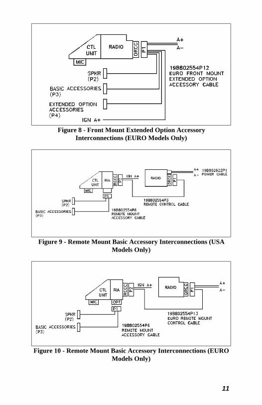
Figure 8 - Front Mount Extended Option AccessoryInterconnections (EURO Models Only)
Figure 9 - Remote Mount Basic Accessory Interconnections (USAModels Only)
Figure 10 - Remote Mount Basic Accessory Interconnections (EUROModels Only)

12
Figure 11 - Remote Mount Extended Option AccessoryInterconnections (USA Models Only)
Figure 12 - Remote Mount Extended Option AccessoryInterconnections (EURO Models Only)
Power Cable
The USA power cable (19B802622P1) consists of a red lead A+ and ablack lead A- connected to a molded 2-pin power connector andsupplied with ring terminals. The EURO power cable also consists of ared lead A+, a black lead A- and is terminated with ring terminals, but itis connected to P1 of the Accessory Cable or P1 of the Control Cable (inremote applications). To install the power cable:
1. Drill a 5/8-inch hole in the firewall for the cable run and insert therubber grommet. Run the cable through this grommet to the batterylocation. Secure the cable at several locations within the enginecompartment to prevent possible damage to cable.
2. Strip back the insulation approximately 3/8 of an inch from the endof the black lead. Slide one of the large heat shrink sleeves onto thewire and crimp a battery ring terminal onto this lead. Heat shrinkthe sleeve over the crimp connection. Connect the black leaddirectly to the battery negative (-) or ground frame member.
3. Cut off 12-18 inches from the red lead. Strip back the insulationapproximately 3/8 of an inch on each end of the wires. Insert the

13
wire ends into the small openings at the end of each fuse holdersection and crimp a fuse connector to each wire. Prepare the otherend of the short wire in the same manner as in Step 2 and connectto the positive (+) terminal of the battery.
NOTE
Do not install fuse into fuse holder until installation is completed andall connections have been checked.
Figure 13 - Power Cable 19B802622P1 (USA Only)
Accessory Cable
Front Mount
The Basic Accessory Cable, at one end, consists of the basic accessoriesconnector (P3), the speaker connector (P2) and the ignition sense lead.At the other end is plug P1. P1 connects to the Option/Remote ControlConnector (ORCC) which is mounted on the back of the radio. TheEURO Accessory Cable also contains the red and black leads of thePower Cable.
NOTE: The EURO ORCC is the opposite gender from the USA ORCC.The Extended Option Accessory Cable is the same as the Basic Cablebut with the addition of the Extended Option Plug (P4). See Figures 14-17.

14
Figure 14 - USA Front Mount Standard Accessory Cable19B802554P1
(19B802554, Sh.1, Rev. 19)
15
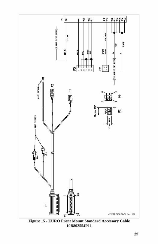
Figure 15 - EURO Front Mount Standard Accessory Cable19B802554P11
(19B802554, Sh.9, Rev. 19)

16
Figure 16 - USA Front Mount Extended Option Accessory Cable19B802554P2
(19B802554, Sh.2, Rev. 19)
17
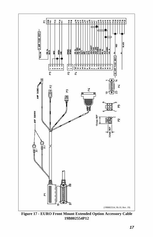
Figure 17 - EURO Front Mount Extended Option Accessory Cable19B802554P12
(19B802554, Sh.10, Rev. 19)

18
Remote Mount
The Basic Accessory Cable, at one end, consists of the basic accessoriesconnector (P3) and the speaker connector (P2). At the other end is theplug P1. P1 will connect to the Option Connector (OPT) which ismounted on the back of the Radio Interface Adapter (RIA). TheExtended Option Accessory Cable is the same as the Basic Cable butwith the addition of the Extended Option Plug (P4). See Figures 18 and19.
Figure 18 - Remote Mount Standard Accessory Cable 19B802554P6
(19B802554, Sh.5, Rev. 19)

19
Figure 19 - Remote Mount Extended Option Accessory Cable19B802554P7
(19B802554, Sh.6, Rev. 19)

20
Ignition Sense (All Applications)
NOTE
• The radio as shipped from the factory has the "ignition sense"feature disabled. As such the radio will be powered ON or OFF asdetermined by the front panel ON/OFF/VOLUME control only(assuming A+ and A- are connected). If it is desired to enable the"ignition sense" feature, open top cover of radio and remove shieldfrom logic PWB. Slide switch SW601 from position 3-2 to 1-2.Replace shield and top cover. Be sure to apply correct torque toscrews holding top cover in place. See Maintenance Manual.
• The "Accessory" point should drop to ZERO volts when crankingthe engine and return to +12 volts after the engine is started. If apoint is chosen that drops to a voltage between zero and +12 volts,the radio may execute a power-up cycle several times during startup. It is recommended that the terminal be measured with avoltmeter to be sure it shuts off (goes to zero volts) during thecranking of the engine.
The fuse holder must be attached to the yellow sense lead along with thering terminal as follows:
1. Cut the yellow sense lead approximately 6-12" from the end thatwill be connected to the power source.
2. Strip the insulation from each end of the short lead and from theend of the long lead at least 3/8".
3. Insert the stripped end of the long lead and one end of the short leadinto the narrow end of each fuse holder half.
4. Crimp the leads in the fuse holder halves with a crimping tool.
5. Insert the 3 amp fuse into one end of the fuse holder and join thetwo fuse holder halves firmly together.
6. Attach the ring terminal to the end of the short lead and connectthis lead to the ignition "ON" sense point [preferably an"Accessory" point (in the vehicle fuse panel) that is switched onwhen the vehicle ignition switch is in the ACCESSORY and RUNpositions].

21
CAUTION
Certain problems may be encountered when accessory equipment isconnected to the ignition or accessory lines of the vehicle, where theselines may have large filter capacitors and a leakage path present. Ifthe radio does not turn off within a reasonable amount of time afterthe ignition is turned off, first try a different accessory or ignitionsense pick up point in the vehicle. Many vehicles have more than onecircuit that is switched by the ignition switch, and one may beavailable that does not have large filter capacitors or a leakage pathpresent.
If a different pickup point cannot be found, then add a 470-ohm, 1-watt resistor from the ignition sense pick point to ground. This willdischarge the capacitor(s) or reduce the leakage voltage to a lowvalue. Current drain through this resistor will be minimal (less than0.03A) when the ignition is switched on.
Control Cable (Remote Mount Only)
The Control Cable is used to connect the Control Unit (through the RIA)to the Radio Transceiver in remote applications. Plug P2, at one end,connects to the Remote Control Cable Connector (RCCC) which ismounted on the back of the RIA. The Ignition Sense wire is also part ofP2. The other end of the Control Cable (P1) connects to the ORCCwhich is mounted on the back of the radio. P1 of the EURO ControlCable also contains the Power Cable leads. See Figures 20-23.
CONTROL UNIT MOUNTING (REMOTEAPPLICATIONS ONLY)
1. Using the bracket as a template, mark and drill the mounting holes.Be sure to leave enough room at the rear of the control unit for thecable connector. Refer to Figure 24 for control unit mountingbracket installation.
2. Secure the mounting bracket using the four No. 10 x 3/4 self-tapping screws supplied (use No. 10 x 1-1/2 if needed.).
3. Secure the control unit to the bracket with the two 1/4-20 x 5/8 hexhead screws and lock washers provided.

22
Figure 20 - USA Remote Control Cable 19B802554P3
(19B802554, Sh.3, Rev. 19)

23
Figure 21 - USA Remote Extended Option Control Cable19B802554P4
(19B802554, Sh.4, Rev. 19)

24
Figure 22 - USA Extended Options Remote Control Cable19B802554P13
(19B802554, Sh.11, Rev. 19)

25
Figure 23 - EURO Extended Options Remote Control Cable19B802554P14
(19B802554, Sh.12, Rev. 19)

26
Figure 24 - Control Unit Mounting Bracket Installation
SPEAKER D2LS1F
The speaker kit includes the speaker, mounting bracket and connectingcable. Mount the speaker so it is directed to the operator but does notpresent a hazard in the event of an accident. The speaker may bemounted on the lower edge of the instrument panel, the firewall or abovethe windshield in some trucks.
1. Use the mounting bracket as a template for locating the mountingholes and mount the speaker as shown in Figure 25.
2. Refer to the applicable installation procedures for connection of thespeaker to the accessory cable.
MICROPHONE HANGER AND/OR HOOKSWITCHMOUNTING
The microphone hanger or hookswitch should be mounted in a locationconvenient to the operator where it will not interfere with the safeoperation of the vehicle or be a hazard to the vehicle passengers. Thehanger or hookswitch is designed to be mounted with the open end ofthe mounting button slot pointed upward. Use the hanger or hookswitchas a template to mark and drill the mounting holes. Mount the hangeror hookswitch with the self-tapping screws provided.
Top Mount Bottom Mount

27
Figure 25 - Speaker Mounting
RADIO MOUNTING AND FINAL HOOK-UP
Front Mount
Typically the bracket shown in Figure 26 is used for Front Mountapplications. The bracket can be mounted so that it is either above orbelow the radio for the user's convenience. The bracket pictured inFigure 24 can also be used for Remote Mount application but is notrecommended for 110 watt VHF radios or 100 watt UHF radios.The following instructions are for a Front Mount installation using thebracket shown in Figure 26.
1. Use the supplied mounting bracket as a template to locate theposition for each of the drill holes. Be sure to leave enough room atthe front and rear of the radio for cable connections. Drill No. 27(9/64) pilot holes.
2. Mount bracket with four 1/4"-14 x 3/4" sheet metal screws (use1/4"-14 x 1-1/2" screws if needed).
3. Place radio into mounting bracket and secure with the four M4 x 10mm hex head screws, M4 flat washers and M4 lock washerssupplied. No. 20 Torx.
4. Connect antenna coaxial cable to antenna connector (TNC).
5. Connect front mount accessory cable connector P1 to theOption/Remote Control Connector (ORCC) and secure with the twocaptive screws in the connector to the radio.
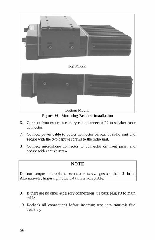
28
Figure 26 - Mounting Bracket Installation
6. Connect front mount accessory cable connector P2 to speaker cableconnector.
7. Connect power cable to power connector on rear of radio unit andsecure with the two captive screws to the radio unit.
8. Connect microphone connector to connector on front panel andsecure with captive screw.
NOTE
Do not torque microphone connector screw greater than 2 in-lb.Alternatively, finger tight plus 1/4 turn is acceptable.
9. If there are no other accessory connections, tie back plug P3 to maincable.
10. Recheck all connections before inserting fuse into transmit fuseassembly.
Top Mount
Bottom Mount

29
Remote Mount Installation
The bracket shown in Figure 27 is used for Remote Mounting (USAOnly). In some applications the bracket shown in Figure 26 can also beused for Remote Mounting. The following instructions are for a RemoteMount installation using the bracket shown in Figure 27.
1. Using the bracket as a template, mark and drill the mounting holesusing a No. 27 drill. Be sure to leave enough room at the rear ofthe radio unit for the cable connections.
2. Secure the Mounting bracket using four 1/4"-14 x 3/4" sheet metalscrews (use 1/4"-14 x 1" if needed.) The bracket can be usedmounted so that it is either above or below the radio for the user'sconvenience.
3. Slide the radio unit into the bracket by aligning bracket guides withgrooves on each side of radio (rear of radio should be inserted first).Slide radio back until screw holes in front of bracket align withscrew holes in side of radio. See Figure 27.
4. Secure radio to the bracket with two M4 x 10 mm socket headscrews provided.
5. Connect antenna coaxial cable to antenna connector (TNC).
6. Connect remote control cable connector P1 to the ORCC connectoron the radio unit and secure with the two captive screws.
7. Connect other end of remote control cable to the remote controlcable connector (RCCC) on the remote control unit.
8. Connect remote mount accessory cable connector P1 to the optionconnector (OPT) on control unit. Then connect the speaker toconnector P2 and accessory connector P3 to any options(hookswitch, etc.). If connector P3 is not used, insulate and tie backto main cable.
9. Recheck all connections and cables. Insert fuse into transmit fuseassembly.

30
Figure 27 - Remote Mounting Bracket Installation
Cassette Mounting (EURO ONLY)
The cassette mounting assembly is designed to mount in a standard DINspace in the instrument panel or console. This mounting permits rapidinsertion and removal of the radio unit from the vehicle. Allconnections are made through a quick disconnect connector at the rearof the cassette mounting assembly to the radio unit. This connector ispart of the cassette assembly. The cassette assembly is shown in Figure28.
Figure 28 - Cassette Assembly
Top Mount
Bottom Mount
31
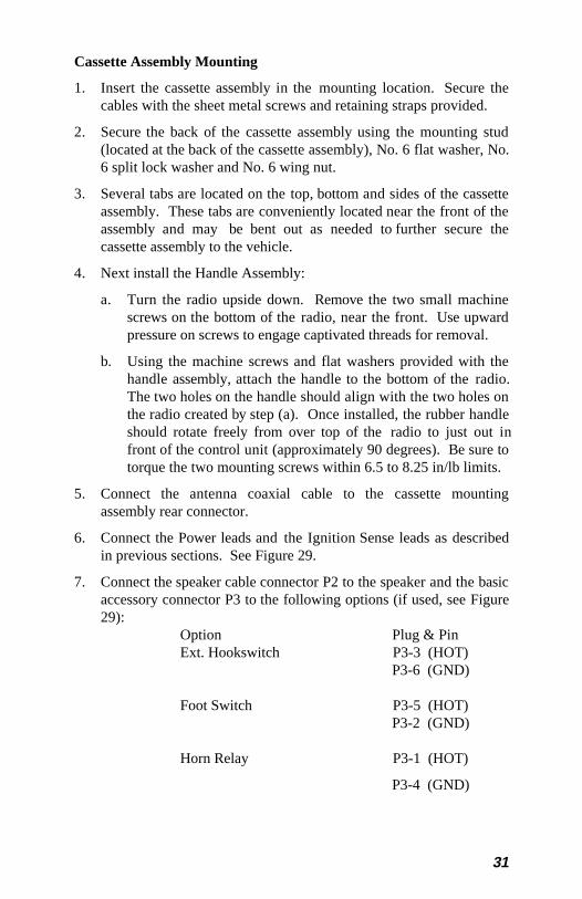
Cassette Assembly Mounting
1. Insert the cassette assembly in the mounting location. Secure thecables with the sheet metal screws and retaining straps provided.
2. Secure the back of the cassette assembly using the mounting stud(located at the back of the cassette assembly), No. 6 flat washer, No.6 split lock washer and No. 6 wing nut.
3. Several tabs are located on the top, bottom and sides of the cassetteassembly. These tabs are conveniently located near the front of theassembly and may be bent out as needed to further secure thecassette assembly to the vehicle.
4. Next install the Handle Assembly:
a. Turn the radio upside down. Remove the two small machinescrews on the bottom of the radio, near the front. Use upwardpressure on screws to engage captivated threads for removal.
b. Using the machine screws and flat washers provided with thehandle assembly, attach the handle to the bottom of the radio.The two holes on the handle should align with the two holes onthe radio created by step (a). Once installed, the rubber handleshould rotate freely from over top of the radio to just out infront of the control unit (approximately 90 degrees). Be sure totorque the two mounting screws within 6.5 to 8.25 in/lb limits.
5. Connect the antenna coaxial cable to the cassette mountingassembly rear connector.
6. Connect the Power leads and the Ignition Sense leads as describedin previous sections. See Figure 29.
7. Connect the speaker cable connector P2 to the speaker and the basicaccessory connector P3 to the following options (if used, see Figure29):
Option Plug & PinExt. Hookswitch P3-3 (HOT)
P3-6 (GND)
Foot Switch P3-5 (HOT)P3-2 (GND)
Horn Relay P3-1 (HOT)
P3-4 (GND)

32
Figure 29 - Cassette Assembly Schematic Diagram
(19C852366, Sh.2, Rev.1)

33
8. Connect the extended option accessory plug P4 to the followingoptions (if used, see Figure 29):
• Mobile Data Terminal• Public Address (External Amplifier)• External Microphone• External Tone Encoder• External Tone Decoder• Output (User Defined)• Input (User Defined)
CAUTION
Refer to accessory manual supplement for details regarding theextended options listed above. DO NOT CONNECT DIRECTLY TOA PC OR DATA TERMINAL. DAMAGE COULD RESULT!!!
9. With the handle assembly in the UNLOCKED position (out in frontof the control unit), insert the radio into the cassette assembly.Slide the radio into the cassette assembly until the back of the radiomeets the back of the cassette assembly.
NOTE
Caution should be used while engaging the radio in the cassette thefirst few times until the cabling in the cassette mount assembly has hadan opportunity to work into its permanent location. To insure properfirst time engagement, the following procedure should be used:
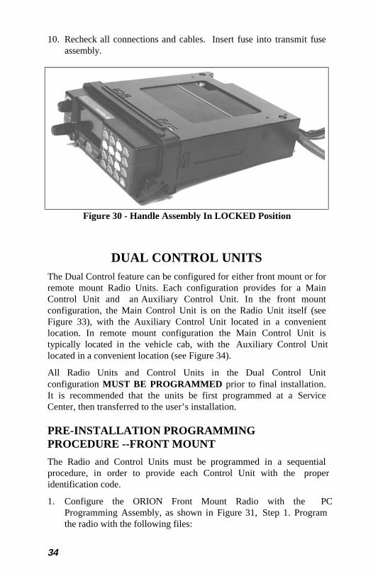
Insert radio into cassette mount opening and slide in until you feelsome spring resistance. Holding the handle, jiggle the radio a bit togive it a chance to find the connectors. Then engage the radio handlein the sheet metal hooks which protrude from the lower corners of thecassette mount casing. Rotate the handle upward to fully engage theradio. See Figure 30. DO NOT FORCE THE CONNECTORENGAGEMENT portion of the travel.
If the radio does not go in using this procedure, a large flat bladescrewdriver may be used to re-position the 37 pin connector slightly toassist the first time engagement.
34
10. Recheck all connections and cables. Insert fuse into transmit fuseassembly.
Figure 30 - Handle Assembly In LOCKED Position
DUAL CONTROL UNITSThe Dual Control feature can be configured for either front mount or forremote mount Radio Units. Each configuration provides for a MainControl Unit and an Auxiliary Control Unit. In the front mountconfiguration, the Main Control Unit is on the Radio Unit itself (seeFigure 33), with the Auxiliary Control Unit located in a convenientlocation. In remote mount configuration the Main Control Unit istypically located in the vehicle cab, with the Auxiliary Control Unitlocated in a convenient location (see Figure 34).
All Radio Units and Control Units in the Dual Control Unitconfiguration MUST BE PROGRAMMED prior to final installation.It is recommended that the units be first programmed at a ServiceCenter, then transferred to the user’s installation.
PRE-INSTALLATION PROGRAMMINGPROCEDURE --FRONT MOUNT
The Radio and Control Units must be programmed in a sequentialprocedure, in order to provide each Control Unit with the properidentification code.
1. Configure the ORION Front Mount Radio with the PCProgramming Assembly, as shown in Figure 31, Step 1. Programthe radio with the following files:

35
Personality Name <USERPERS> User’s personality fileRadio Code OGXXXXX Latest radio code file
(G13 or later vintage)
ADI Code <SAME>Radio Unit ID <SAME>ORION Keypad File <CUBMAP> Keypad definition for
Control Unit B
ORION CU ID CU B Must be Control Unit B
2. Now configure the Front Mount Radio and the Auxiliary ControlUnit together with the PC Programming Assembly, as shown inFigure 31, Step 2. Program this configuration with the followingfiles:
Personality Name <USERPERS> User’s personality fileRadio Code <SAME>ADI Code <SAME>Radio ID <SAME>ORION Keypad Files <CUAMAP> Keypad definition for
Control Unit A
ORION CU ID CU A Must be Control Unit A
Note that the Main Control Unit has ID “B” and the Auxiliary ControlUnit has ID “A” in this configuration.
Figure 31 - ORION Dual Control Unit PC ProgrammingConfiguration
36
PRE-INSTALLATION PROGRAMMINGPROCEDURE -- REMOTE MOUNT
The Radio and Control Units must be programmed in a sequentialprocedure, in order to provide each Control Unit with the properidentification code.
1. Configure the ORION Remote Mount Radio and Auxiliary ControlUnit with the PC Programming Assembly, as shown in Figure 32,Step 1. Program the radio with the following files:
Personality name <USERPERS> User’s personality fileRadio Code OGXXXXX Latest radio code file
(G13 or later vintage)
ADI Code <SAME>Radio Unit ID <SAME>ORION Keypad File <CUBMAP> Keypad definition for
Control Unit BORION CU ID CU B Must be Control Unit B
2. Now configure the Remote Mount Radio, the Main Control Unit,and the Auxiliary Control Unit together with the PC ProgrammingAssembly, as shown in Figure 32, Step 2. Program thisconfiguration with the following files:
Personality Name <USERPERS> User’s personality fileRadio Code <SAME>ADI Code <SAME>Radio ID <SAME>ORION Keypad File <CUAMAP> Keypad definition for
Control Unit AORION CU ID CU A Must be Control Unit A
Note that the Main Control Unit has ID “A” and Auxiliary Control Unithas ID “B” in this configuration.

37
Figure 32 - ORION Dual Control Unit PC ProgrammingConfiguration Remote Mount

38
INSTALLATION INSTRUCTIONS FOR FRONTMOUNT DUAL CONTROL UNITSThe Dual Control Unit feature is configured such that only one controlunit can be used for Extended Option accessories. All Extended Optionaccessories are connected through the Main Control Unit.
1. Referring to Figure 33, run the Dual Control Cable (19B802554P9)between locations for the Radio Unit and Auxiliary Control Unit. Besure to locate the P2/P3 connector assembly at the Radio Unit.
2. After installing Radio Unit mounting hardware in the normalfashion, connect the Dual Control Cable connector (P3) to the RadioUnit. Tighten the two jackscrews on P3. Next, connect theAccessory Cable (19B802554P1 or P2) Connector (P1) to the DualControl Cable Connector (P2), and tighten the jackscrews on P2.Connect the power cable, and install Radio Unit in mountingbracket.
3. After installing the Auxiliary Control Unit in the normal fashion,connect the Dual Control Cable (P1) to Auxiliary Control Unit, andtighten jackscrews.
4. Connect the Remote Mount Accessory Cable (19B802554P6) to theAuxiliary Control Unit.
5. A yellow Ignition Sense lead is provided on the Dual Control Cableand the Front Mount Accessory Cable. If the “Ignition Sense”feature is enabled on the Radio Unit, it is necessary to connect onlyone of the yellow leads provided, whichever is convenient. Tapeback the unused yellow lead (See Page 20 for details).
6. Install the Speakers in convenient locations near the Radio Unit andAuxiliary Control Unit.
7. Install a relay (19A149299P1) from the kits supplied at a locationnear the leads from each speaker. For mounting, use the #8 X 3/4”sheetmetal screw and nutplate supplied with each kit.
8. At a convenient point cut one of the wires in each of the 2-wirespeaker cables, spread the leads, and strip the ends. Crimp a 1/4”tab receptacle to each end.
9. Radio Unit Speaker: Connect the lead nearest the speaker to Pin87A of the relay. Connect the lead nearest the connector to Pin 30of the relay. Connect the connector to the Accessory Cable P2(Refer to Figure 33).
10. Auxiliary Control Unit Speaker: Connect the lead nearest thespeaker to Pin 87 of the relay. Connect the lead nearest the

39
connector to Pin 30 of the relay. Connect the connector to theAccessory Cable P2 (Refer to Figure 33).
11. For each relay: Connect a #18 AWG black wire between the relay,Pin 85 and Accessory Cable P3-1 (labeled “OUT2” on theschematic diagrams in the service manual). Use a 1/4” tabreceptacle on the relay side and mating Molex connector and pinson the accessory cable side. Connect the mating Molex connector tothe Accessory Cable P3 when finished (Refer to Figure 33).
12. For each relay: Connect a #18 AWG red wire to the relay, Pin 86.Cut to length, and connect to the 1 amp fuse holder supplied. Usecrimp on connectors supplied. Connect the other side of the 1 ampfuse holder to A+ battery source or vehicle A+ fuse block. Use #18AWG red wire and ring lug supplied., if needed (See Figure 33).
13. Check dual control operation, using operator’s manual as a testguide. In the PC programming software, make sure the “DUALCONTROL SPEAKER is programmed ACTIVE LOW .
Figure 33 - ORION Dual Control Unit Front Mount/Remote MountInstallation Configuration
INSTALLATION INSTRUCTIONS FOR REMOTEMOUNT DUAL CONTROL UNITS
1. Referring to Figure 34, run the Remote Control Cable(19B802554P3 or P4) between locations for the Radio Unit andMain Control Unit.

40
2. Run the Dual Control Cable (19B802554P9) between locations forthe Radio Unit and Auxiliary Control Unit. Be sure to locate theP2/P3 connector assembly at the radio unit.
3. After installing the Radio Unit in the normal fashion, connect thedual control cable connector (P3) to the Radio Unit. Tighten the twojackscrews on P3. Next, connect the Remote Control Cableconnector (P1) to the Dual Control Cable connector (P2), andtighten jackscrews on P2.
4. After installing the Main Control Unit in the normal fashion,connect the Remote Control Cable (P2) to the Main Control Unit,and tighten jackscrews.
5. After installing the auxiliary control unit in the normal fashion,connect the Dual Control Cable (P1) to the Auxiliary Control Unit,and tighten jackscrews.
6. Connect the accessory cable (19B802554P6) to the AuxiliaryControl Unit. Connect either the accessory cable (19B802554P6) orthe extended option accessory cable (19B802554P7) to the MainControl Unit, as appropriate.
7. A yellow ignition sense lead is provided on each control cable. Ifthe “Ignition Sense” feature is enabled on the Radio Unit, it isnecessary to connect only one of the yellow leads provided,whichever is convenient. Tape back the unused yellow lead. Seepage 20 for details.
8. Install the speakers in convient locations near each control unit.
9. Install a relay (19A149299P1) from the kits supplied at a locationnear the leads from each speaker. For mounting use the #8 X 3/4”sheetmetal screw and nutplate supplied with each kit.
10. At a convenient point cut one of the wires in each of the 2-wirespeaker cables, spread the leads, and strip the ends. (Crimp a 1/4”tab receptacle to each end.
11. Main Control Unit Speaker: Connect the lead nearest the speakerto Pin 87 of the relay. Connect the lead nearest the connector to Pin30 of the relay. Connect connector to the accessory cable P2 (Referto Figure 34).
12. Auxiliary Control Unit Speaker: Connect the lead nearest thespeaker to Pin 87A of the relay. Connect the lead nearest theconnector to Pin 30 of the relay. Connect the connector to accessorycable P2 (Refer to Figure 34).

41
13. For Each Relay: Connect a #18 AWG black wire between the relay,Pin 85 and accessory cable P3-1 (labeled “OUT2” on schematicdiagrams in the service manual). Use a 1/4” tab receptacle on therelay side and a mating Molex connector and pins on the accessorycable side. Connect the mating Molex connector to the accessorycable P3 when finished (Refer to Figure 34).
14. For Each Relay: Connect one end of a #18 AWG red wire to therelay, Pin 86. Cut the lead to length, and connect the other end tothe 1 amp fuse holder supplied. Use crimp on connectors supplied.Connect the other side of the 1 amp fuse holder to the A+ batterysource or a vehicle A+ fuse block. Use a #18 AWG red wire and aring lug supplied, if needed (Refer to Figure 34).
15. Check dual control operation, using the operator’s manual as a testguide. In the PC programming software, make sure the “DUALCONTROL SPEAKER is programmed ACTIVE HIGH .
Figure 34 - ORION Dual Control Unit Remote Mount/RemoteMount Installation Configuration

42
Figure 35 - Remote Mount Dual Control Cable 19B802554P9
(19B802554, Sh.7, Rev. 19)
43
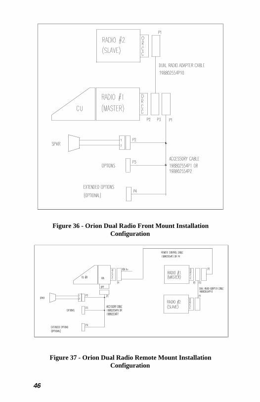
DUAL RADIO UNITSThe Dual Radio feature can be configured either for two remote mount radiounits or one front mount unit and one remote mount unit. In remote mountconfigurations the Control Unit is typically located in the vehicle cab, withthe Radio Units located side-by-side in vehicle trunk. In front/remote mountconfigurations the front mount unit is located in the vehicle cab, with theremote mount unit located in a convenient location nearby. Theremote/remote mount configuration is the preferred installation, since aseparate control unit is required to program the remote unit in a front/remotemount configuration.
The following Dual Radio Unit configurations are not allowed:
1. Any configuration using a DIN cassette mount.
2. Any installation where Extended Options are required from both RadioUnits. Extended Options are supported in one Radio Unit only.
PRE-INSTALLATION PROGRAMMINGPROCEDURE
All Radio Units in the Dual Radio configuration MUST BEPROGRAMMED prior to final installation. It is recommended that the unitsbe first programmed at a Service Center, then transferred to the user'sinstallation.
These configurations provide for a Master Radio Unit and a Slave RadioUnit. In the remote/remote mount configuration, the Master Radio Unit isalways the radio most directly connected to the Control Unit. In thefront/remote mount configuration, the Master Radio Unit is always the frontmount radio. Extended Options are allowed only in the Master Radio Unit.Programming each radio is straightforward, except that one radio isprogrammed as a Master, and one as a Slave.
1. Decide which Radio Unit shall be the Master Unit. Configure the radiofor programming as shown in the applicable service section manual.
2. In the "Multi-Radio" field of the PC programmer, select "Master".
3. Program unit normally. Include Extended Option features, ifpurchased.
4. Now configure the "Slave" Radio Unit for programming. Be sure to usethe programming configuration for remote mount, and supply therequired control unit, if for a front/remote mount dual radioconfiguration.

44
5. In the "Multi-Radio" field of the PC programmer, select "Slave". RadioUnits are now ready for vehicle installation.
6. Program normally. Do not include Extended Option features.
INSTALLATION INSTRUCTIONS FORFRONT/REMOTE MOUNT DUAL RADIOCONFIGURATION.
1. Plan the mounting locations of the two Radio Units. Note that themaximum cable length allowed between the two radios is two meters.Referring to Figure 36, run Dual Radio Cable (19B802554P10) betweenlocations for Master and Slave Radio Units. Be sure to locate the P2/P3connector assembly at the Master Radio Unit.
2. After installing Master Radio Unit mounting hardware, connect theDual Radio Cable Connector (P3) to the Master Radio Unit. Tightenthe two jackscrews on P3. Next connect the Accessory Cable(19B802554P1 or P2) Connector (P1) to the Dual Radio CableConnector (P2), and tighten to jackscrews on P2.
3. Connect Microphone and Accessories. Refer to Accessory InstallationManual for proper connection of Accessories.
4. Connect Power Cable, and Antenna, then install Master Radio Unit inmounting bracket.
5. Connect "IGN A+" lead, if option is desired. Be sure internal SwitchSW601 is set properly. Refer to Page 20 of this manual for details.
6. After installing Slave Radio Unit in its mounting hardware, connectDual Radio Cable (P1), and tighten jackscrews. Be sure SW601 settingon Slave Radio Unit is same as for Master Radio Unit. Connect PowerCable and Antenna to Slave Radio.
7. Check Dual Radio operation, using Operator's Manual as test guide.
INSTALLATION INSTRUCTIONS FORREMOTE/REMOTE MOUNT DUAL RADIOCONFIGURATION.
1. Plan the mounting locations of the two Radio Units. Note that themaximum cable length allowed between the two radios is two meters.Referring to Figure 37, run Dual Radio Cable (19B802554P10) betweenlocations for Master and Slave Radio Units. Be sure to locate the P2/P3connector assembly at the Master Radio Unit.

45
2. After installing Master Radio Unit mounting hardware, connect theDual Radio Cable Connector (P3) to the Master Radio Unit. Tightenthe two jackscrews on P3.
3. Next route the Remote Control Cable (19B802554P3 or P4) betweenControl Head and Master Radio locations. After installing ControlHead, connect Remote Control Cable Connector (P2) to Control Head.
4. Connect "IGN A+" lead, if option is desired. Be sure internal SwitchSW601 on Master Radio is set properly. Refer to Page 20 of thismanual for details.
5. Connect Accessory Cable (19B802554P6 or P7) Connector (P1) toControl Head.
6. Connect Microphone and Accessories. Refer to Accessory InstallationManual for proper connection of Accessories.
7. Now connect Remote Control Cable Connector (P1) to the Dual RadioCable Connector (P2), and tighten to jackscrews on P2.
8. Connect Power Cable, and Antenna, then install Master Radio Unit inmounting bracket.
9. After installing Slave Radio Unit in its mounting hardware, connectDual Radio Cable (P1), and tighten jackscrews. Be sure SW601 settingon Slave Radio Unit is same as for Master Radio Unit. Connect PowerCable and Antenna to Slave Radio.
10. Check Dual Radio operation, using operator's manual as test guide.
46
Figure 36 - Orion Dual Radio Front Mount InstallationConfiguration
Figure 37 - Orion Dual Radio Remote Mount InstallationConfiguration

47
Figure 38 Dual Radio Control Cable (19B802554P10)
(19B802554, Sh.8, Rev. 19)

Ericsson Inc.Private Radio SystemsMountain View RoadLynchburg, Virginia 245021-800-528-7711 (Outside USA, 804-528-7711) Printed in U.S.A.