Embed Size (px)
Citation preview
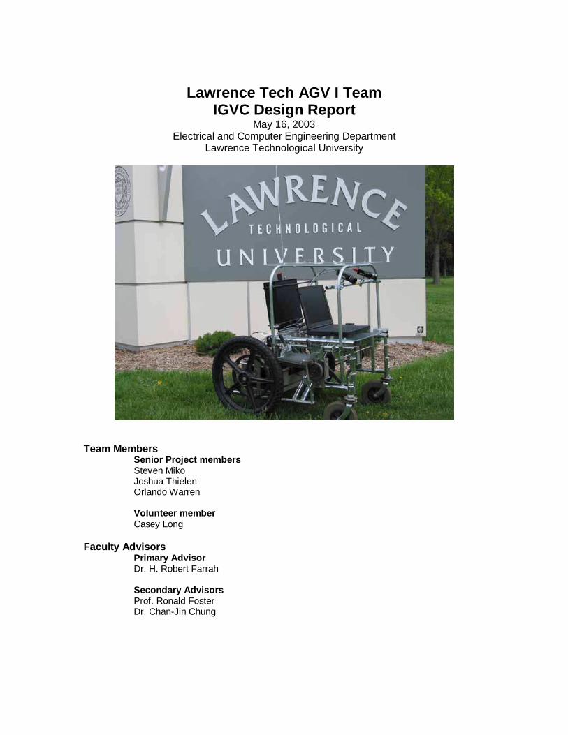
Lawrence Tech AGV I Team IGVC Design Report
May 16, 2003 Electrical and Computer Engineering Department
Lawrence Technological University
Team Members Senior Project members Steven Miko Joshua Thielen Orlando Warren
Volunteer member Casey Long
Faculty Advisors Primary Advisor Dr. H. Robert Farrah Secondary Advisors Prof. Ronald Foster Dr. Chan-Jin Chung
Contents
1 Introduction .............................................................................................................1
2 Design Process .......................................................................................................1
3 Team Organization..................................................................................................2
4 Drive Train and Structural Design................ ............................................................3
5 Power System.........................................................................................................4
6 Motor Control System............................. .................................................................5
6.1 Microcontroller and Motor Drivers.............. ..........................................................5
6.2 E-Stop Circuitry ...................................................................................................6
6.3 Hall Effect Sensors............................ ..................................................................6
7 Navigation System ..................................................................................................7
7.1 Laptop Computer.................................................................................................7
7.2 Digital Cameras...................................................................................................7
7.3 GPS receiver.......................................................................................................8
8 Software Design......................................................................................................8
8.1 Software Architecture ..........................................................................................8
8.2 Software Simulation and Testing ................ .........................................................8
8.3 Miscellaneous Applications..................................................................................9
8.4 Autonomous Challenge Application ............... ......................................................9
8.5 Navigation Challenge Algorithm................. ........................................................11
8.6 Follow-the-Leader Algorithm..............................................................................11
9 Problems and Outcomes............................ ...........................................................12
10 Cost Analysis ........................................................................................................13
11 Conclusion ............................................................................................................13

1
1 Introduction
Lawrence Technological University will be competin g in the 11 th Annual Intelligent
Ground Vehicle competition for the first time with the new LTU AGV I vehicle. The
primary goal in building this vehicle is to compete in the Autonomous Challenge event of
the IGVC. Secondary goals include competing in the Navigation Challenge and Follow-
the-Leader Event.
The AGV I is based on an electric wheelchair frame . The wheelchair features two
DC belt-drive motors with fail-safe electromechanic al brakes. A custom digital motor
controller houses custom electronic circuitry including a microcontroller, two motor
drivers, a manual emergency stop (E-stop) button, a nd a wireless E-stop receiver. The
vehicle’s sensors include two FireWire industrial d igital cameras, Hall-effect wheel speed
sensors, and a Global Positioning System (GPS) rece iver. A laptop serves as the
vehicle's main processing unit.
Custom software on the laptop performs visual proc essing to detect lanes,
obstacles and potholes using simultaneous video str eams from the digital cameras. The
software features a Windows-based Graphical User In terface (GUI) that allows easy
modifications to software parameters, including cam era positions, motor speed
calibrations, and image processing options. An opti onal USB joystick allows manual
control of the vehicle when it is not operating aut onomously.
2 Design Process
Since this is the first time a Lawrence Tech team has entered the IGVC, and
because the size of the team is relatively small, a somewhat simple design process was
used: the linear sequential model, or waterfall mod el. Figure 1 illustrates this model.
Figure 1: Design process
2
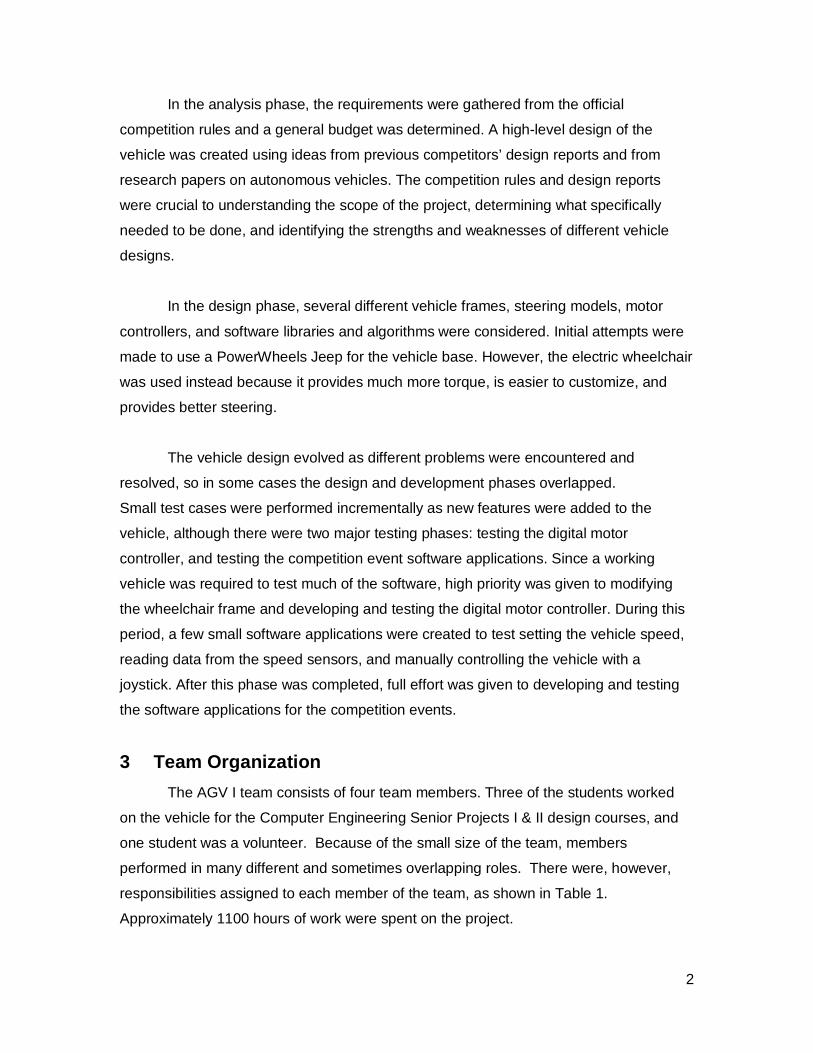
In the analysis phase, the requirements were gathe red from the official
competition rules and a general budget was determin ed. A high-level design of the
vehicle was created using ideas from previous compe titors’ design reports and from
research papers on autonomous vehicles. The competi tion rules and design reports
were crucial to understanding the scope of the proj ect, determining what specifically
needed to be done, and identifying the strengths an d weaknesses of different vehicle
designs.
In the design phase, several different vehicle fra mes, steering models, motor
controllers, and software libraries and algorithms were considered. Initial attempts were
made to use a PowerWheels Jeep for the vehicle base . However, the electric wheelchair
was used instead because it provides much more torq ue, is easier to customize, and
provides better steering.
The vehicle design evolved as different problems w ere encountered and
resolved, so in some cases the design and developme nt phases overlapped.
Small test cases were performed incrementally as ne w features were added to the
vehicle, although there were two major testing phas es: testing the digital motor
controller, and testing the competition event softw are applications. Since a working
vehicle was required to test much of the software, high priority was given to modifying
the wheelchair frame and developing and testing the digital motor controller. During this
period, a few small software applications were crea ted to test setting the vehicle speed,
reading data from the speed sensors, and manually c ontrolling the vehicle with a
joystick. After this phase was completed, full effo rt was given to developing and testing
the software applications for the competition event s.
3 Team Organization
The AGV I team consists of four team members. Thre e of the students worked
on the vehicle for the Computer Engineering Senior Projects I & II design courses, and
one student was a volunteer. Because of the small size of the team, members
performed in many different and sometimes overlappi ng roles. There were, however,
responsibilities assigned to each member of the tea m, as shown in Table 1.
Approximately 1100 hours of work were spent on the project.
3
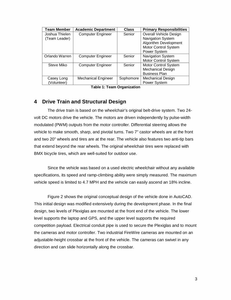
Team Member Academic Department Class Primary Responsibilities Joshua Thielen (Team Leader)
Computer Engineer Senior Overall Vehicle Design Navigation System Algorithm Development Motor Control System Power System
Orlando Warren Computer Engineer Senior Navigation System Motor Control System
Steve Miko Computer Engineer Senior Motor Control S ystem Mechanical Design Business Plan
Casey Long (Volunteer)
Mechanical Engineer Sophomore Mechanical Design Power System
Table 1: Team Organization
4 Drive Train and Structural Design
The drive train is based on the wheelchair’s origi nal belt-drive system. Two 24-
volt DC motors drive the vehicle. The motors are dr iven independently by pulse-width
modulated (PWM) outputs from the motor controller. Differential steering allows the
vehicle to make smooth, sharp, and pivotal turns. T wo 7” castor wheels are at the front
and two 20" wheels and tires are at the rear. The v ehicle also features two anti-tip bars
that extend beyond the rear wheels. The original wh eelchair tires were replaced with
BMX bicycle tires, which are well-suited for outdoo r use.
Since the vehicle was based on a used electric whe elchair without any available
specifications, its speed and ramp-climbing ability were simply measured. The maximum
vehicle speed is limited to 4.7 MPH and the vehicle can easily ascend an 18% incline.
Figure 2 shows the original conceptual design of t he vehicle done in AutoCAD.
This initial design was modified extensively during the development phase. In the final
design, two levels of Plexiglas are mounted at the front end of the vehicle. The lower
level supports the laptop and GPS, and the upper le vel supports the required
competition payload. Electrical conduit pipe is use d to secure the Plexiglas and to mount
the cameras and motor controller. Two industrial Fi reWire cameras are mounted on an
adjustable-height crossbar at the front of the vehi cle. The cameras can swivel in any
direction and can slide horizontally along the cros sbar.

4
Figure 2: Initial CAD Model of Vehicle
The digital motor controller was designed to fit i nto the mounting bracket of the
wheelchair’s original motor controller. The manual E-stop pushbutton is built directly into
the motor controller enclosure and is conveniently located at the rear center of the
vehicle within the 2'-4' height range specified by the competition rules. The two-level
Plexiglas structure provides easy access to the pay load, as well as convenient
positioning of the laptop on the lower level. It a lso protects most of the vehicle
components, including the laptop and cameras, from light rain.
5 Power System
The main power supply of the vehicle operates at 2 4 V. 12-V and 5-V
subsystems provide power to the digital cameras and electronics. Table 2 shows the
maximum possible current drain from of each of thes e systems.
Device Voltage Current Drain Motors/Motor Drivers 24 V 60A Digital Cameras 12 V 1 A Electronics 5 V (TTL), 12 V 200 mA
Table 2: Power System and Maximum Current Drain
Two 12-V 75 A/h deep-cycle lead-acid batteries are connected in series to
provide the vehicle with at least one hour of runni ng power when the vehicle is operating
5
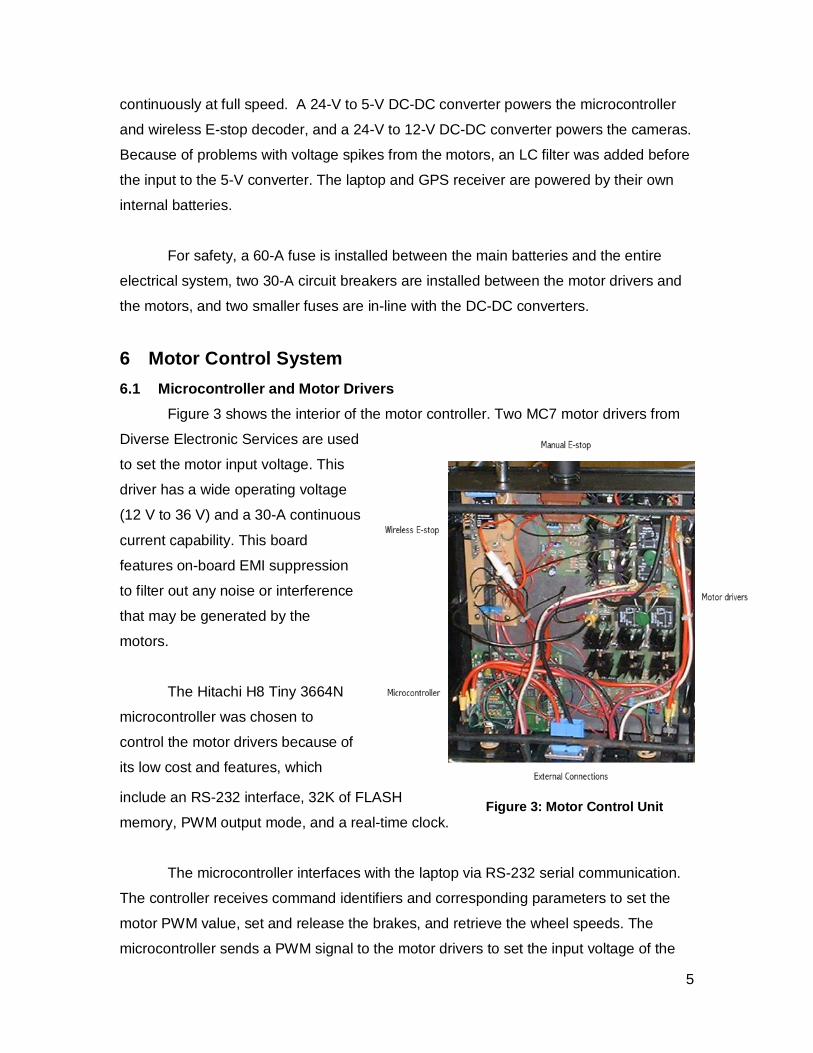
Figure 2: Motor Control Unit
Figure 3: Motor Control Unit
continuously at full speed. A 24-V to 5-V DC-DC co nverter powers the microcontroller
and wireless E-stop decoder, and a 24-V to 12-V DC- DC converter powers the cameras.
Because of problems with voltage spikes from the mo tors, an LC filter was added before
the input to the 5-V converter. The laptop and GPS receiver are powered by their own
internal batteries.
For safety, a 60-A fuse is installed between the m ain batteries and the entire
electrical system, two 30-A circuit breakers are in stalled between the motor drivers and
the motors, and two smaller fuses are in-line with the DC-DC converters.
6 Motor Control System
6.1 Microcontroller and Motor Drivers
Figure 3 shows the interior of the motor controlle r. Two MC7 motor drivers from
Diverse Electronic Services are used
to set the motor input voltage. This
driver has a wide operating voltage
(12 V to 36 V) and a 30-A continuous
current capability. This board
features on-board EMI suppression
to filter out any noise or interference
that may be generated by the
motors.
The Hitachi H8 Tiny 3664N
microcontroller was chosen to
control the motor drivers because of
its low cost and features, which
include an RS-232 interface, 32K of FLASH
memory, PWM output mode, and a real-time clock.
The microcontroller interfaces with the laptop via RS-232 serial communication.
The controller receives command identifiers and cor responding parameters to set the
motor PWM value, set and release the brakes, and re trieve the wheel speeds. The
microcontroller sends a PWM signal to the motor dri vers to set the input voltage of the
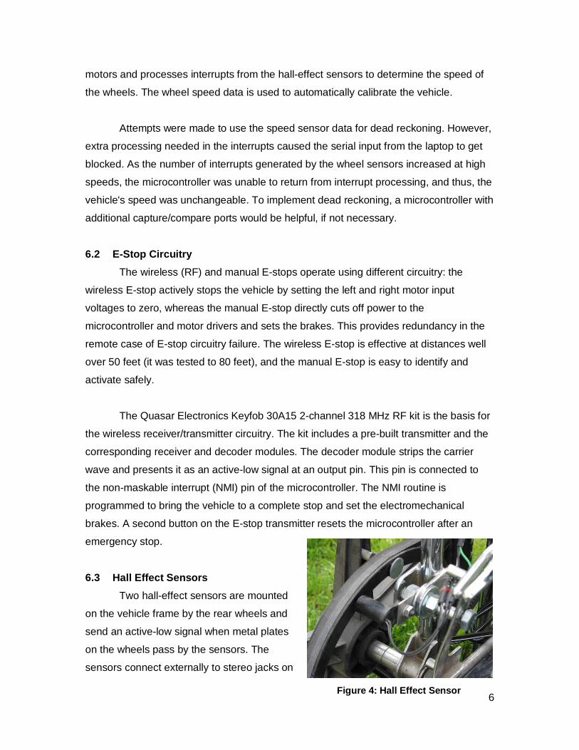
6Figure 4: Hall Effect Sensor
motors and processes interrupts from the hall-effec t sensors to determine the speed of
the wheels. The wheel speed data is used to automat ically calibrate the vehicle.
Attempts were made to use the speed sensor data fo r dead reckoning. However,
extra processing needed in the interrupts caused th e serial input from the laptop to get
blocked. As the number of interrupts generated by t he wheel sensors increased at high
speeds, the microcontroller was unable to return fr om interrupt processing, and thus, the
vehicle's speed was unchangeable. To implement dead reckoning, a microcontroller with
additional capture/compare ports would be helpful, if not necessary.
6.2 E-Stop Circuitry
The wireless (RF) and manual E-stops operate using different circuitry: the
wireless E-stop actively stops the vehicle by setti ng the left and right motor input
voltages to zero, whereas the manual E-stop directl y cuts off power to the
microcontroller and motor drivers and sets the brak es. This provides redundancy in the
remote case of E-stop circuitry failure. The wirele ss E-stop is effective at distances well
over 50 feet (it was tested to 80 feet), and the ma nual E-stop is easy to identify and
activate safely.
The Quasar Electronics Keyfob 30A15 2-channel 318 MHz RF kit is the basis for
the wireless receiver/transmitter circuitry. The ki t includes a pre-built transmitter and the
corresponding receiver and decoder modules. The dec oder module strips the carrier
wave and presents it as an active-low signal at an output pin. This pin is connected to
the non-maskable interrupt (NMI) pin of the microco ntroller. The NMI routine is
programmed to bring the vehicle to a complete stop and set the electromechanical
brakes. A second button on the E-stop transmitter r esets the microcontroller after an
emergency stop.
6.3 Hall Effect Sensors
Two hall-effect sensors are mounted
on the vehicle frame by the rear wheels and
send an active-low signal when metal plates
on the wheels pass by the sensors. The
sensors connect externally to stereo jacks on

7
Figure 5: Digital Camera
the motor controller, which are internally connecte d to the microcontroller's interrupt
request pins. The distance between the metal plates is known, and the time between
each sensor is determined using the microcontroller 's real-time clock. Using this
information, the speed of both rear wheels can be d etermined.
7 Navigation System
7.1 Laptop Computer
An LTU TechBook (Pentium III 800MHz) laptop is the primary processing unit for
the vehicle. All of the high-level image processing and navigation software is executed
on the laptop. The laptop communicates with the mic rocontroller and GPS using RS-232
serial connections. Since there is only one serial port on the laptop, the GPS is
connected via a USB-to-serial converter. A FireWire PCMCIA CardBus adapter is used
to interface the digital cameras to the laptop.
7.2 Digital Cameras
Two Unibrain Fire-I 400 Industrial
IEEE1394 (FireWire) digital cameras
provide image data for obstacle, lane, and
pothole detection. These cameras were
chosen for their high frame rate, support
for multiple simultaneous connections,
operating system independence, easy
mounting interface, and sturdy
construction.
3.6-mm C-mount lenses are used to provide a 53.6 ° viewing angle. The lenses
have manually adjustable irises, so they can be con figured for a variety of lighting
conditions. The cameras also include auto-contrast/ brightness/shutter modes to
automatically adjust to changes in lighting. Auto-i ris cameras and lenses would have
been ideal, however, they are at least $600 more pe r camera.

8
7.3 GPS receiver
A Garmin GPS 76 receiver provides vehicle position and heading information for
waypoint navigation. The receiver features WAAS sup port and is accurate to within at
least 3 meters.
8 Software Design
8.1 Software Architecture
All AGV I software is written in C, C++, and Java. Microsoft Windows 2000 is
used as the operating system on the laptop. The fol lowing software development
libraries were used on the laptop:
• Intel OpenCV for image processing.
• Microsoft Windows API for serial, GUI, and threadin g support
• OpenGL for the inverse perspective transformation
• Carnegie Mellon IEEE1394 camera driver and interfac e library
• Java3D and Xj3D for 3D simulation
The laptop software uses a custom dynamic-link lib rary (DLL) to encapsulate the
serial protocol for the motor controller. This DLL is used by all AGV I software and
provides the following functionality:
• Basic vehicle commands
• Vehicle calibration
• Vehicle navigation functions
The vehicle calibration functions include synchronizing the PWM commands with actual
wheel speeds and saving and loading calibration fil es to disk. Navigation functions
include setting the vehicle's turn radius, and in t he future, will include functions to
execute linear and curved path (these functions had to be removed because of problems
with dead reckoning noted in section 5.1).
8.2 Software Simulation and Testing
A custom 3D simulator was created to provide test images for the Autonomous
Challenge software. The simulator is written in Ja va using the Java 3D package. A
sample course, based on the Autonomous Challenge sa mple map on the 2002 IGVC
video, was created in 3D Studio MAX and exported in VRML format for use by the
9
simulator. The simulator displays an overhead view of the course, as well as views of the
left and right camera images. Keyboard input contro ls the position and heading of the
vehicle, and snapshots of the camera views can be w ritten to disk. A sample simulation
snapshot is shown in section 8.4 (figure 6).
The simulator was originally designed for real-tim e simulation using a TCP/IP
client/server model for communication between the s imulator and the Autonomous
Challenge application. Unfortunately, off-screen rendering and network transmission
time caused the simulator to be too slow for practi cal use. After the vehicle was
assembled, live testing was the primary method used to test its operation.
8.3 Miscellaneous Applications
A simple GUI speedometer application was created t o test the speed sensors
and determine the maximum speed of the vehicle. Bas ed on data from this application,
the vehicle speed was limited to 4.7 MPH. This spee d was determined when the vehicle
was suspended above the ground, so the actual speed of the vehicle when running on
the ground is significantly lower and depends on th e load and the terrain.
A joystick application retrieves the joystick X an d Y positions using the Windows
Multimedia API and converts the Cartesian coordinat es to left and right motor speed
values. This application is very helpful in verifyi ng the operation of the motor controller
and manually controlling the vehicle.
8.4 Autonomous Challenge Application
The Autonomous Challenge application provides an i ntuitive user interface to
view camera images, initialize the motor controller serial interface, start and stop the
vehicle, and set the vehicle and camera parameters, . All settings are saved to the
Windows Registry and are restored when the applicat ion is re-opened.
The following algorithm is used in the Autonomous C hallenge application:
1. Smooth the camera images using Gaussian blurring
2. Find the bottom edges of all objects that are ye llow, orange, or white (figure 7)
3. Apply inverse perspective mapping (IPM) to resto re the texture of the x-z plane
4. Overlay the left and right remapped images to cr eate a single image

10
5. Create a minimum-area convex hull bounding the c ombined image
6. Find the best turn radius among a set of predefi ned turn radii (Figure 8)
7. Set the left and right wheel velocities based on the turn radius and the desired
vehicle speed
Figure 8: Final Image and Selected Turn Radius
Only the bottom edges of obstacles are detected so that obstacles do not appear
as infinitely long objects after the inverse perspe ctive transformation. Bounding the
image closes any gaps in the lane lines caused by d ashed lines, shadows, or obstacles
blocking the cameras’ views. On each frame, the bes t determined turn radius is used to
steer the vehicle and an alternate turn radius is a lso determined. Both the primary and
alternate turn radii are stored in a list of most r ecently selected turn radii. Lanes and
obstacles are treated the same: they are represente d by set pixels on the final overhead
image. The best turn radius is selected as the curv e that reaches the y coordinate
farthest from the top of the image before reaching a set pixel.
Figure 7: Color Filtering Figure 6: Simulation Image
11
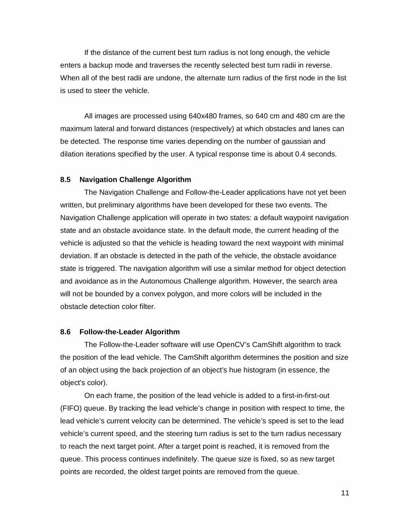
If the distance of the current best turn radius is not long enough, the vehicle
enters a backup mode and traverses the recently sel ected best turn radii in reverse.
When all of the best radii are undone, the alternat e turn radius of the first node in the list
is used to steer the vehicle.
All images are processed using 640x480 frames, so 640 cm and 480 cm are the
maximum lateral and forward distances (respectively ) at which obstacles and lanes can
be detected. The response time varies depending on the number of gaussian and
dilation iterations specified by the user. A typica l response time is about 0.4 seconds.
8.5 Navigation Challenge Algorithm
The Navigation Challenge and Follow-the-Leader app lications have not yet been
written, but preliminary algorithms have been devel oped for these two events. The
Navigation Challenge application will operate in tw o states: a default waypoint navigation
state and an obstacle avoidance state. In the defau lt mode, the current heading of the
vehicle is adjusted so that the vehicle is heading toward the next waypoint with minimal
deviation. If an obstacle is detected in the path o f the vehicle, the obstacle avoidance
state is triggered. The navigation algorithm will u se a similar method for object detection
and avoidance as in the Autonomous Challenge algori thm. However, the search area
will not be bounded by a convex polygon, and more c olors will be included in the
obstacle detection color filter.
8.6 Follow-the-Leader Algorithm
The Follow-the-Leader software will use OpenCV’s C amShift algorithm to track
the position of the lead vehicle. The CamShift algo rithm determines the position and size
of an object using the back projection of an object ’s hue histogram (in essence, the
object's color).
On each frame, the position of the lead vehicle is added to a first-in-first-out
(FIFO) queue. By tracking the lead vehicle’s change in position with respect to time, the
lead vehicle’s current velocity can be determined. The vehicle’s speed is set to the lead
vehicle’s current speed, and the steering turn radi us is set to the turn radius necessary
to reach the next target point. After a target poin t is reached, it is removed from the
queue. This process continues indefinitely. The que ue size is fixed, so as new target
points are recorded, the oldest target points are r emoved from the queue.
12
9 Problems and Outcomes
This original vehicle CAD design (shown earlier in Figure 2) had significant flaws.
The required competition E-stop position was not co nsidered, the cameras and laptop
were not protected from light rain, and a laser sca nner was not actually purchased.
During the construction of the vehicle frame, the o riginal design was modified to address
these problems and to provide better camera mountin g positions and more payload
space.
Another significant problem encountered was that t he laptop could not
communicate with the microcontroller despite extens ive testing of the microcontroller
with several desktop PCs. This problem is solved in the final design by: 1) opening the
communications (COM) port on the laptop, 2) resetti ng the microcontroller after the COM
port is open, 3) sending an initialization string f rom the microcontroller, and 4) receiving
the initialization string on the laptop. These step s can now be performed easily since the
second button on the wireless E-stop transmitter wa s configured to reset the
microcontroller.
In the initial motor control design, there was no circuitry to release the
electromechanical brakes on the wheelchair. It was assumed that the brakes were set by
applying a voltage. This proved to be an incorrect assumption since the brakes are fail-
safe and need 24 volts applied to be released. Duri ng testing, the motor drivers failed
after the manual emergency stop was pressed because the high (stall) current through
the motors generated a large voltage spike, which, in turn, destroyed the hexfets on the
motor drivers. The motor drivers were subsequently repaired. In order to prevent this
from happening in the future, two metal-oxide varis tors were placed across the motor
terminals to suppress motor transients and extra ci rcuitry was added to release the
electromechanical brakes.
As previously mentioned, because of budget constra ints, a laser scanner could
not be purchased. This problem was overcome by the development of an algorithm
based solely on image processing (section 7).
13
Also, some difficulties were encountered using the OpenCV cvcam library for
capturing frames from the digital cameras. This pro blem was solved by using the
Carnegie-Mellon IEEE1394 camera driver and library.
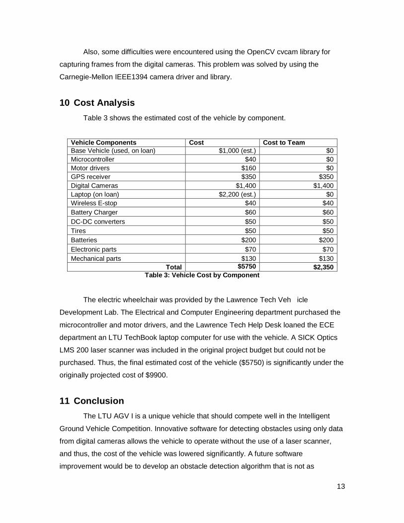
10 Cost Analysis
Table 3 shows the estimated cost of the vehicle by component.
Vehicle Components Cost Cost to Team Base Vehicle (used, on loan) $1,000 (est.) $0 Microcontroller $40 $0 Motor drivers $160 $0 GPS receiver $350 $350 Digital Cameras $1,400 $1,400 Laptop (on loan) $2,200 (est.) $0 Wireless E-stop $40 $40 Battery Charger $60 $60 DC-DC converters $50 $50 Tires $50 $50 Batteries $200 $200 Electronic parts $70 $70 Mechanical parts $130 $130
Total $5750 $2,350 Table 3: Vehicle Cost by Component
The electric wheelchair was provided by the Lawren ce Tech Veh icle
Development Lab. The Electrical and Computer Engine ering department purchased the
microcontroller and motor drivers, and the Lawrence Tech Help Desk loaned the ECE
department an LTU TechBook laptop computer for use with the vehicle. A SICK Optics
LMS 200 laser scanner was included in the original project budget but could not be
purchased. Thus, the final estimated cost of the ve hicle ($5750) is significantly under the
originally projected cost of $9900.
11 Conclusion
The LTU AGV I is a unique vehicle that should comp ete well in the Intelligent
Ground Vehicle Competition. Innovative software for detecting obstacles using only data
from digital cameras allows the vehicle to operate without the use of a laser scanner,
and thus, the cost of the vehicle was lowered signi ficantly. A future software
improvement would be to develop an obstacle detecti on algorithm that is not as

14
dependent on knowledge of the obstacle colors. Also , the simulator could be rewritten in
OpenGL and optimized for real-time use. Future hard ware improvements include adding
a laser scanner, automatically positioning the came ras, and implementing a closed-loop
motor controller.

15
Special Thanks To
The Lawrence Tech Entrepreneurial Committee
The Lawrence Tech Alumni Association
Dr. H Robert Farrah, Professor, Electrical and Comp uter Engineering
Mrs. Martha Thompson, Lab Coordinator, Electrical a nd Computer Engineering
Mr. Nick Brancik, Technical Automotive Advisor, Veh icle Development Lab
Prof. Ronald Foster, Department Chair, Electrical a nd Computer Engineering
Dr. Chan-Jin Chung, Professor, Math and Computer Sc ience
Prof. Ben Sweet, Professor, Electrical and Computer Engineering


![[SOFTWARE DESIGN FOR IGVC COMPETITON ]](https://img.dokumen.tips/doc/110x75/61dab469fc8c63207126e873/software-design-for-igvc-competiton-.jpg)