Embed Size (px)
Citation preview
Lawrence Berkeley National Laboratory
SAFETY NOTE
author: D. Shuman
cat. code: RP3135
serial :10688 rev: A
dept.: Mech.Engineering
page: 1 of 15
date:2/20/2013
loc: Berkeley
revision history:
A - no revision, initial releaseproj: NEXT-100 XENON TPC
Energy Plane, Tooling
title: Pressure Safety Note, Pressure Test Chamber
Prepared by:
Responsible Designer - Derek Shuman
Reviewed by:
EH&S Pressure Safety Subject Matter Expert - Scott Robinson
Approved by:
Engineering Division Director - Kem Robinson or Designee (Ken Chow)
This is an Engineering Safety Note for a small pressure vessel to be used for gas pressure testing
prototype photomultiplier tube (PMT) enclosures for the NEXT-100 Xenon Time Projection Chamber (TPC).
The PMT enclosures operate under external xenon gas pressure of 15 bara. It may also be used for other,
similar purposes, such as to test gas permeation into various materials.
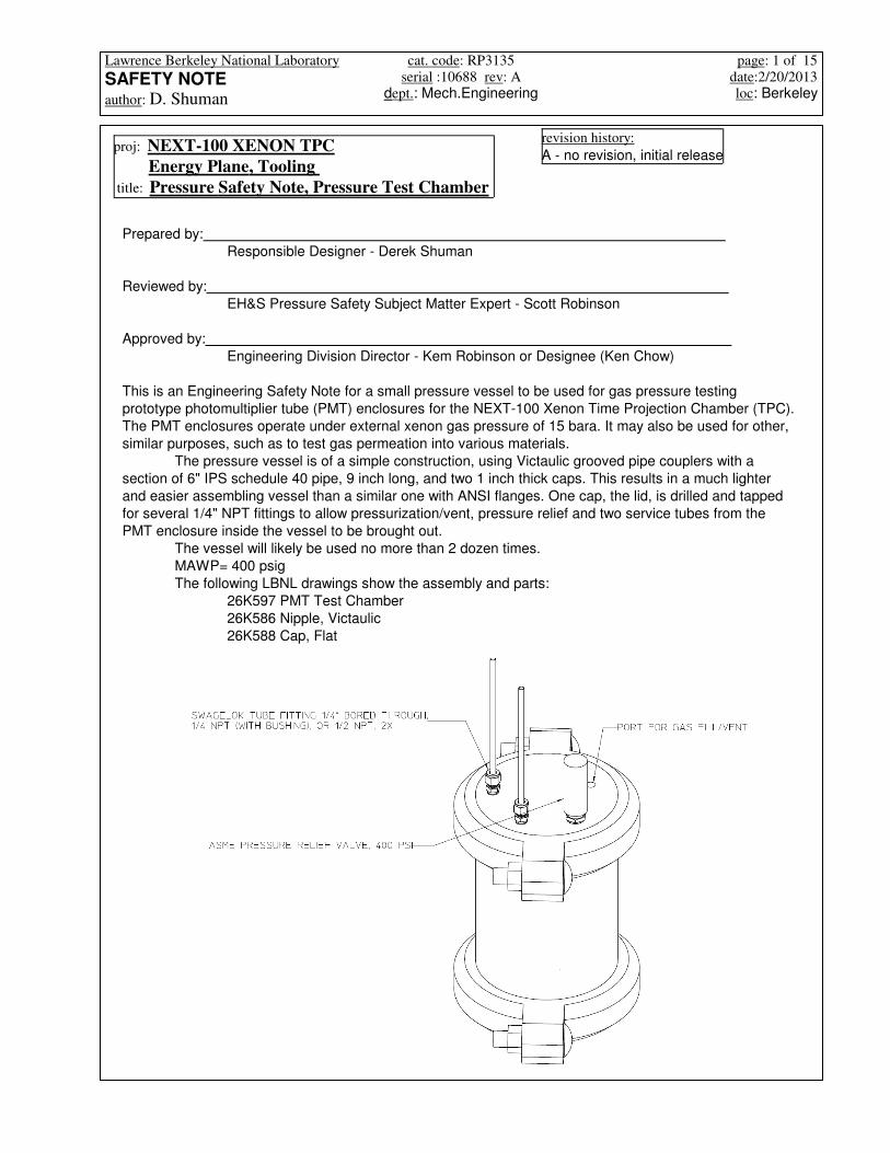
The pressure vessel is of a simple construction, using Victaulic grooved pipe couplers with a
section of 6" IPS schedule 40 pipe, 9 inch long, and two 1 inch thick caps. This results in a much lighter
and easier assembling vessel than a similar one with ANSI flanges. One cap, the lid, is drilled and tapped
for several 1/4" NPT fittings to allow pressurization/vent, pressure relief and two service tubes from the
PMT enclosure inside the vessel to be brought out.
The vessel will likely be used no more than 2 dozen times.
MAWP= 400 psig
The following LBNL drawings show the assembly and parts:
26K597 PMT Test Chamber
26K586 Nipple, Victaulic
26K588 Cap, Flat
Lawrence Berkeley National Laboratory
SAFETY NOTE
author: D. Shuman
cat. code: RP3135
serial :10688 rev: A
dept.: Mech.Engineering
page: 2 of 15
date:2/20/2013
loc: Berkeley
Table of Contents page #
1. Background........................................................................................................................................2
2. Assembly and Operation .....................................................................................................................2
3. Maximum Operating, Allowable Pressures............................................................................................4
4. Hazards Analysis................................................................................................................................5
5. Pressure Test procedure......................................................................................................................6
6. Pipe and Coupler calculations.............................................................................................................6
7. Lid and Cap calculations.....................................................................................................................7
8. Material Certifications .......................................................................................................................11
9. Pressure, Gauge Test ......................................................................................................................13
10. Vessel Markings..............................................................................................................................15
1. Background
NEXT is a collaboration between LBNL and other institutions to build a detector to observe neutrinoless
double beta decay. The NEXT-100 TPC will contain 100 kg of enriched xenon gas at up to 15 bara
pressure. The PMTs used inside this gas volume cannot withstand this pressure, so an enclosure has
been designed to protect it.
Although not the subject of this Note, this PMT enclosure is designed in accordance with ASME
PV code sec VIII div. 1, and sees external pressure only. It is fabricated from OFE (C10100) copper for
high radiopurity, and is heavily built to provide shielding from background gamma rays. The enclosure
incorporates a single crystal sapphire window for the PMT to view light produced in the xenon gas; this is
the critical strength component of the enclosure due to its brittle failure mode. There will be a total of 60 of
these windows inside the TPC, and they have been designed using the methodology of the Weibull
distribution, in combination with linear elastic fracture mechanics to provide a quantitative estimate of
reliability. These windows will be pressure tested hydrostatically in a separate test chamber (described in
a separate note) before using.
This pressure test chamber is for the purpose of demonstrating proper PMT operation under high
pressure conditions. We are primarily interested in measuring Xenon permeation through O-ring seals,
and the achievable vacuum inside the enclosure under actual external pressure, using different conduit
tubing diameters. We want to verify the collapse resistance of the different tubing diameters (after bending
to shape). We plan to use an aluminum alloy substitute "window" here for most tests to avoid any brittle
fracture possibility. We may run a pressure test with a pre-tested sapphire window installed; we will first
do this without a PMT inside the enclosure, and with a high flow filter or muffler installed on the outside
tubing (open to atmosphere) so as to capture any fragments of sapphire should it fracture.
The maximum pressure to be applied to the enclosure, for testing is 1.6 x 15 bara = 360 psia;
therefore we set 350 psig as the MOP for the test vessel described below.
2. Assembly and Operation
The pressure vessel is simply a section of 6 inch schedule 40 stainless steel pipe, grooved on
each end for Victaulic grooved pipe couplers (type 77, flexible). The ends are capped with stainless steel
lids machined from plate. Below is the assembly drawing showing the PMT enclosure mounted inside the
pressure vessel:

Lawrence Berkeley National Laboratory
SAFETY NOTE
author: D. Shuman
cat. code: RP3135
serial :10688 rev: A
dept.: Mech.Engineering
page: 3 of 15
date:2/20/2013
loc: Berkeley
The PMT enclosure prototype module, (with cable conduit and vacuum sense tubes assembled) is shown in
the following figure:
The lid is placed over the tubes and the top clamp assembled. The through-bored Swagelok tube fittings
have plastic ferrules to avoid tube deformation that would disallow lid removal without cutting the tube.
The space between the vessel and the enclosure will then be pressurized with inert gas, thus
applying an external pressure to the PMT enclosure. During this time, a vacuum will be applied through the
cable conduit tube, and the vacuum inside the PMT enclosure will be measured with a vacuum gauge
connected to the vacuum sense tube. In further testing, the PMT will be assembled inside the enclosure, with

Lawrence Berkeley National Laboratory
SAFETY NOTE
author: D. Shuman
cat. code: RP3135
serial :10688 rev: A
dept.: Mech.Engineering
page: 4 of 15
date:2/20/2013
loc: Berkeley
electrical signals brought out through the cable conduit/vacuum tube; allowing the PMT operation to be
verified. The PMT operates at a modestly high voltage 1.5 kV and we are concerned about flashover on the
pins and resistor base inside the enclosure, so gas permeation through O-rings while under external pressure
is something we want to quantify before operating the PMT.
Gas pressure for enclosure testing will be provided with the gas test rig pictured below, which was
used for pressure testing the HP Xenon TPC (Eng. Note 10506)
3. Maximum operating and allowable Pressures:
For the gas permeation tests, the maximum operating pressure need only be 15 bara (14 barg), however we
would like to verify a minimum safety factor on the enclosure, including the sapphire window (though it will be
pretested separately in a hydrostatic tester) of 1.6 against collapse or 24 bara (23barg):
MOP 350psi:= MOP 23.816 bar=
ASME certified pressure relief valves are available in 400 psi (closest size)
MAWP 400psi:=
Check, is MAWP > 110% MOP? (per PUB3000 recommendations)
MAWP 1.1MOP> 1= (1=true, 0=false)
All components except the pipe, lid and cap, are manufacturer rated for working pressures higher than
MAWP above. The lid and cap are designed and made here at LBNL.

Lawrence Berkeley National Laboratory
SAFETY NOTE
author: D. Shuman
cat. code: RP3135
serial :10688 rev: A
dept.: Mech.Engineering
page: 5 of 15
date:2/20/2013
loc: Berkeley
The enclosure will be tested initially with an aluminum window, so all parts are ductile. Eventually, once
the prototype sapphire windows on the PMT enclosure are hydrostatically tested, they may be installed
on the PMT enclosure and pressurized with gas in this vessel. The first time this is done, the conduit
tube should be left open to air (not connected to a vacuum pump) and a standard air exhaust filter
installed to catch any fragments. The sense line should be plugged.
Sapphire window fracture
The Victaulic couplers are very straightforward to assemble, however, if the coupling lips are not fully
seated into the grooves on the pipe, the assembly will not hold much pressure, and the lid of cap will pop
off with high velocity when pressurizing. The two clamps will not come together when bolting, so this is
the necessary condition to check for; THERE SHOULD BE NO SIGNIFICANT GAP BETWEEN THE
TWO SEMICIRCULAR CLAMPS WHEN FULLY BOLTED UP. The clamps should be bolted up as tight
as possible with a large wrench, however this is primarily to avoid any possibility of nuts coming loose
between pressure cycling; pressure capacity is not dependent on bolt torque, once snug. The gaskets
should be installed on the pipe with either Victaulic water soluble grease or with a vacuum grease.
Grease the sealing surfaces and OD on the gasket; grease the inside surfaces on the clamps where they
contact the gasket. Several types of couplers are feasible, type 07 (rigid) type 77(flexible) or type 05
(standard); we use type 77 here. See chart below. Type 741 couplers must not be used.
Improper Assembly
PUB3000 classifies pressure vessel with less than 75 kJ stored energy as low hazard, which this vessel
is. However the pressure is higher than 150 psi and is gas pressure, so we treat as high hazard.
U 2.108kJ=UPh Vh⋅
γ 1−1
Pl
Ph
γ 1−
γ
−
:=
Vh 42.412 in3
=Vhπ
46in
29⋅ in:=
Pipe is a 6" schedule 40 IPS ( 6.625" OD x .28" thk) welded 304 stainless steel. It is likely
ASME SA-312 (general purpose austenitic stainless welded and seamless pipe), though
provenance is unknown. Length inside is 9 inch. Volume, empty, is:
UPh Vh⋅
γ 1−1
Pl
Ph
γ 1−
γ
−
:=
Pl 1bar:=Ph MAWP:=
monatomic gasγ 1.667:=
Stored Energy (formula from PUB3000):
4. Hazards:

Lawrence Berkeley National Laboratory
SAFETY NOTE
author: D. Shuman
cat. code: RP3135
serial :10688 rev: A
dept.: Mech.Engineering
page: 6 of 15
date:2/20/2013
loc: Berkeley
5. Pressure Test Procedure
Vessel is to be assembled as in the drawing above, without the enclosure inside, but with a copper
tubing loop simulating both the bent cable conduit and sense lines. This tube loop is left open to air on
the exterior. Use plastic ferrules on tube. A certified pressure gauge is to be installed on one of the
remaining lid ports and a hydrostatic water pump and vent valve connected to the remaining port on a
tee, the vent valve being for air bleed-off.
The hydrostatic pump being used (in bldg. 78-103) has its own pressure regulator which has
been set to 600 psi; if tested subsequently with a different pump, a pressure relief valve of 600 psig shall
be installed on the lid. Vessel shall be filled slowly with water with vent valve open until air is purged.
Raise test pressure to 600 psi. Vessel shall be held at pressure for 5 minutes to verify that leakage is
negligible. Slight leakage around seals or threads is tolerable, as most testing of enclosures will be fairly
short duration.
After successful testing, engrave, etch, or otherwise permanently label the following information
on the pipe, lid and cap:
MAWP = 400 psi
Safety Note = 10688A
6. Pipe and Coupler Calculations
Maximum allowable stress, from 2009b ASME PV code sec II, part D - table 1A,
S 17000psi:= E 1:= Rpipe 3.03in:= tpipe .28in:=
From UG-27 pressure rating would be:
Ppipe_max
S E⋅ tpipe⋅
Rpipe 0.6tpipe+:= Ppipe_max 1.488 10
3× psi=
However, pressure rating is conjunction with the Victaulic type 77 flanges is given in Victaulic publication #
17.09 "Pressure Ratings and End Loads for Victaulic Ductile Iron Grooved couplings on stainless steel
pipe" :
Therefore:

Lawrence Berkeley National Laboratory
SAFETY NOTE
author: D. Shuman
cat. code: RP3135
serial :10688 rev: A
dept.: Mech.Engineering
page: 7 of 15
date:2/20/2013
loc: Berkeley
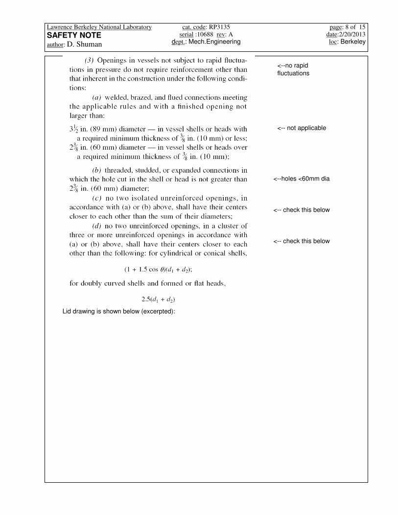
UG-36 (c) (3) Strength and Design of finished Openings:
UG-39(a) General, rules in this section are exempted for openings that do not exceed size and spacing
limits of UG-36(c)(3)
UG-39 Reinforcement Required for Openings in Flat heads
This completes the calculation for the (bottom) cap. The (top) lid is identical thickness and has four 1/4-NPT
tapped holes in it:
th t> 1=th 1.0 in⋅:=
(1)t 0.579 in=t d
C P⋅
Splate E⋅⋅:=
Minimum head thickness is then:
Splate S283:=
from Table UW12(weld efficiency)E 1=
from table 1A ASME PV code, sec. II, part DS304 16700psi:=S283 15700psi:=
material : steel SA-283 carbon steel or better (plate is SA-240 304L stainless steel
(UNS30403)
P 27.218 bar=P MAWP:=
from fig. UG-34:C 0.3:=attachment factor:
d 6.625in:=diameter:
From UG-34 Unstayed Flat Heads and Covers
7. Lid and Cap Calculations
This publication also states that a one time only overpressure of 1.5x the max. working pressure
is acceptable for a field test. We will not exceed the working pressure for the hydraulic pressure
test
pipe has a cut groovePmax_SSpipe_Vic77 750psi:=
Lawrence Berkeley National Laboratory
SAFETY NOTE
author: D. Shuman
cat. code: RP3135
serial :10688 rev: A
dept.: Mech.Engineering
page: 8 of 15
date:2/20/2013
loc: Berkeley
<--no rapid
fluctuations
<-- not applicable
<--holes <60mm dia
<-- check this below
<-- check this below
Lid drawing is shown below (excerpted):

Lawrence Berkeley National Laboratory
SAFETY NOTE
author: D. Shuman
cat. code: RP3135
serial :10688 rev: A
dept.: Mech.Engineering
page: 9 of 15
date:2/20/2013
loc: Berkeley
holes do not form clusters so (d) is not applicable; closest hole spacing is
ds 2.5in:= These are 1/4NPT holes do .44in:=
Reinforcement is not needed, and in fact, 1/2-NPT holes could be used, where d=.73 in
Nevertheless we calculate here:

Lawrence Berkeley National Laboratory
SAFETY NOTE
author: D. Shuman
cat. code: RP3135
serial :10688 rev: A
dept.: Mech.Engineering
page: 10 of 15
date:2/20/2013
loc: Berkeley
2A1 A> 1=
Check:
t, th as defined in UG-34A1 0.513 in2
=A1 L1 th t−( )⋅:=
Area available for reinforcement, on each side of opening axis
This is greater than the nominal plate thickness, so all excess plate material can be counted for
reinforcement.
L2 2.5 in=L2 min 2.5th( ):=
from UG-40(c) Limits of Reinforcement, limit perpendicular to vessel wall:
We can see in the drawing above, that these limits will not overlap
L1 1.22 in=L1 max d 0.5d th+,( ):=
from UG-40(b) Limits of Reinforcement, limit parallel vessel wall, from hole axis:
UG-39 (b)(2) holes may be reinforced individually as above, as no two holes have a distance between
their centers less than 2x their avg. diameter ( 2d=1inch < min. distance)
t as defined in UG-34A 0.127 in2
=A 0.5d t⋅ t tn⋅ 1 fr1−( )⋅+:=
Area or reinforcement required UG-39(b)(1), total:
d 0.44 in=
fr1 1.0:=tn 0in:=th 1 in=t 0.579 in=d do:=
We have no nozzle, weld or reinforcement, reinforcement area is only available as extra shell
thickness

Lawrence Berkeley National Laboratory
SAFETY NOTE
author: D. Shuman
cat. code: RP3135
serial :10688 rev: A
dept.: Mech.Engineering
page: 11 of 15
date:2/20/2013
loc: Berkeley
8. Cap and Lid material certs:
The remainder of the vessel will consist of Swagelok tube fittings, stainless steel, in tube sizes

Lawrence Berkeley National Laboratory
SAFETY NOTE
author: D. Shuman
cat. code: RP3135
serial :10688 rev: A
dept.: Mech.Engineering
page: 12 of 15
date:2/20/2013
loc: Berkeley
from 1/4 to 7/16. Swagelok pressure ratings are based on the size of the lowest rated end
connection, which is 1/4-NPT. From Swagelok publication MS-01-140.pdf :
Lawrence Berkeley National Laboratory
SAFETY NOTE
author: D. Shuman
cat. code: RP3135
serial :10688 rev: A
dept.: Mech.Engineering
page: 13 of 15
date:2/20/2013
loc: Berkeley
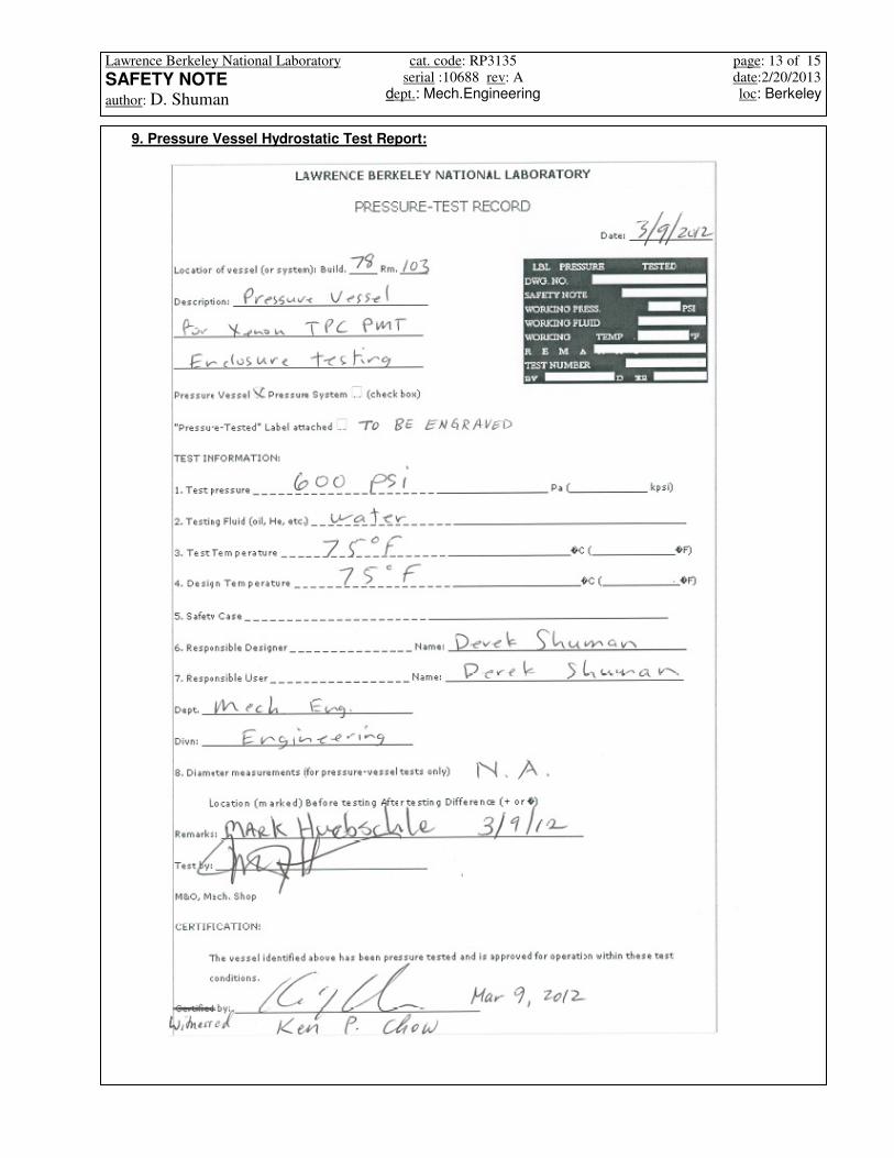
9. Pressure Vessel Hydrostatic Test Report:

Lawrence Berkeley National Laboratory
SAFETY NOTE
author: D. Shuman
cat. code: RP3135
serial :10688 rev: A
dept.: Mech.Engineering
page: 14 of 15
date:2/20/2013
loc: Berkeley
Pressure Test Gauge Certification

Lawrence Berkeley National Laboratory
SAFETY NOTE
author: D. Shuman
cat. code: RP3135
serial :10688 rev: A
dept.: Mech.Engineering
page: 15 of 15
date:2/20/2013
loc: Berkeley
10. Markings on Vessel