Embed Size (px)
Citation preview

Owner’s Manual
LAWN TRACTOR18.5 HP, 42” MowerElectric Start6 Speed Transaxle
This product has a low emission engine which operates differently from previously built engines. Before you start the engine, read and understand this Owner’s Manual.
IMPORTANT:Read and follow all Safety Rules and Instructions before op er at ing this equipment.
For answers to your questions about this product, Call:
1-800-659-5917Sears Craftsman Help Line5 am - 5 pm, Mon - Sat
Sears, Roebuck and Co., Hoffman Estates, IL 60179 U.S.A.
Model No.917.27581
Visit our Craftsman website:www.sears.com/crafts man
02494
2
TABLE OF CONTENTS
WARRANTY
Warranty ................................................. 2Safety Rules ........................................... 3Product Specifi cations............................ 6Assembly/Pre-Operation ........................ 8Operation.............................................. 11Maintenance Schedule ......................... 17
Maintenance......................................... 17Service and Adjustments...................... 21Storage................................................. 27Troubleshooting .................................... 28Repair Parts.......................................... 32Sears Service .........................Back Cover
LIMITED WARRANTY ON CRAFTSMAN RIDING EQUIPMENT For two (2) years from the date of purchase, if this Craftsman Riding Equipment is maintained, lubricated and tuned up according to the instructions in the owner’s manual, Sears will repair or replace free of charge any parts that are found to be defective in material or workmanship according to the guidelines of coverage listed below. Sears will also provide free labor for these applicable warranted parts for the two full years. During the fi rst 30 days of purchase, there will be no charges to service the product at your home for issues covered by this warranty. (See exclusions below). For your conve-nience, IN HOME warranty service will still be available after the fi rst 30 days of pur-chase, but a trip charge will apply. This charge will be waived if the Crafts man product is dropped off at an authorized Sears location. For the nearest authorized Sears location, please call 1-800-4-MY-HOME®. This warranty applies only while this product is within the United States.
This Warranty does not cover:• Expendable items which become worn during normal use, including but not limited to
blades, spark plugs, air cleaners, belts, and oil fi lters. Standard Maintenance Servicing, oil changes, or tune-ups• Tire replacement or repair caused by punctures from outside objects, such as nails,
thorns, stumps, or glass.• Repairs necessary because of operator abuse, including but not limited to, damage
caused by towing objects beyond the capability of the riding equipment, impacting objects that bend the frame or crankshaft, or over-speeding the engine.
• Repairs necessary because of operator negligence, including but not limited to, elec-trical and mechanical damage caused by improper storage, failure to use the proper grade and amount of engine oil, failure to keep the deck clear of fl ammable debris, or failure to maintain the equipment according to the instructions contained in the owner’s manual.
• Engine (fuel system) cleaning or repairs caused by fuel determined to be con tam i- nat ed or oxidized (stale). In general, fuel should be used within 30 days of its pur-chase date.
• Normal deterioration and wear of the exterior fi nishes, or product label replacement.• Riding equipment used for commercial or rental purposes. LIMITED WARRANTY ON BATTERYFor ninety (90) days from date of purchase, if any battery included with this riding equip-ment proves defective in material or workmanship and our testing determines the battery will not hold a charge, Sears will replace the battery at no charge. During the fi rst 30 days of purchase, there will be no charges to replace the battery at your HOME. After the fi rst 30 days, for your convenience, IN-HOME warranty service will still be avail-able but a trip charge will apply. This charge will be waived if the Craftsman product is dropped off at an authorized Sears location. For the nearest authorized Sears location, please call 1-800-4-MY-HOME®.
This battery warranty applies only while this product is within the United States. This warranty gives you specifi c legal rights, and you may also have other rights, which vary, from state to state.
Sears, Roebuck and Co.,Dept.817WA, Hoffman Estates, IL 60179
3
SAFETY RULES
I. GENERAL OPERATION • Read, understand, and follow all
instructions on the machine and in the manual before starting.
• Do not put hands or feet near rotating parts or under the machine. Keep clear of the discharge opening at all times.
• Only allow responsible adults, who are familiar with the instructions, to operate the machine.
• Clear the area of objects such as rocks, toys, wire, etc., which could be picked up and thrown by the blades.
• Be sure the area is clear of bystand-ers before operating. Stop machine if anyone enters the area.
• Never carry passengers.• Do not mow in reverse unless abso-
lutely necessary. Always look down and behind before and while backing.
• Never direct discharged material toward anyone. Avoid discharging material against a wall or obstruction. Material may ricochet back toward the operator. Stop the blades when cross-ing gravel surfaces.
• Do not operate machine without the entire grass catcher, discharge guard, or other safety devices in place and working.
• Slow down before turning.• Never leave a running machine
unattended. Always turn off blades, set parking brake, stop engine, and remove keys before dismounting.
• Disengage blades when not mowing. Shut off engine and wait for all parts to come to a complete stop before clean-ing the machine, removing the grass catcher, or unclogging the discharge guard.
• Operate machine only in daylight or good artifi cial light.
• Do not operate the machine while under the infl uence of alcohol or drugs.
• Watch for traffi c when operating near or crossing roadways.
• Use extra care when loading or un-loading the machine into a trailer or truck.
• Always wear eye protection when oper-ating machine.
• Data indicates that operators, age 60 years and above, are involved in a large percentage of riding mower-re-lated injuries. These operators should evaluate their ability to operate the riding mower safely enough to protect themselves and others from serious injury.
• Follow the manufacturer’s recommen-dation for wheel weights or counter-weights.
• Keep machine free of grass , leaves or other debris build-up which can touch hot exhaust / engine parts and burn. Do not allow the mower deck to plow leaves or other debris which can cause build-up to occur. Clean any oil or fuel spillage before operating or storing the machine. Allow machine to cool beforestorage.
IMPORTANT: This cutting machine is ca pa ble of amputating hands and feet and throw-ing objects. Failure to observe the fol low ing safety instructions could result in serious injury or death.
WARNING: In order to prevent ac- ci den tal starting when setting up, trans- port ing, ad just ing or making repairs, always dis con nect spark plug wire and place wire where it can not contact spark plug.
WARNING: Do not coast down a hill in neutral, you may lose control of the tractor.
WARNING: Tow only the at tach ments that are rec om mend ed by and comply with spec i fi ca tions of the man u fac tur er of your tractor. Use common sense when towing. Operate only at the lowest possible speed when on a slope. Too heavy of a load, while on a slope, is dan ger ous. Tires can lose trac tion with the ground and cause you to lose control of your tractor.
WARNING: Engine exhaust, some of its constituents, and certain vehicle com- po nents contain or emit chem i cals known to the State of Cal i for nia to cause can cer and birth defects or oth er re pro duc tive harm.
WARNING: Battery posts, terminals and related accessories contain lead and lead compounds, chemicals known to the State of Cal i for nia to cause can cer and birth defects or oth er re pro duc tive harm. Wash hands after handling.
4
SAFETY RULES
II. SLOPE OPERATIONSlopes are a major factor related to loss of control and tip-over accidents, which can result in severe injury or death. Opera-tion on all slopes requires extra caution. If you cannot back up the slope or if you feel uneasy on it, do not mow it.• Mow up and down slopes, not across.• Watch for holes, ruts, bumps, rocks, or
other hidden objects. Uneven terrain could overturn the machine. Tall grass can hide obstacles.
• Choose a low ground speed so that you will not have to stop or shift while on the slope.
• Do not mow on wet grass. Tires may lose traction.
Always keep the machine in gear when going down slopes. Do not shift to neutral and coast downhill.
• Avoid starting, stopping, or turning on a slope. If the tires lose traction, dis-engage the blades and proceed slowly straight down the slope.
• Keep all movement on the slopes slow and gradual. Do not make sudden changes in speed or direction, which could cause the machine to roll over.
• Use extra care while operating ma-chine with grass catchers or other at-tachments; they can affect the stability of the machine. Do no use on steep slopes.
• Do not try to stabilize the machine by putting your foot on the ground.
• Do not mow near drop-offs, ditches, or embankments. The machine could suddenly roll over if a wheel is over the edge or if the edge caves in.
III. CHILDRENTragic accidents can occur if the operator is not alert to the presence of children. Children are often attracted to the machine and the mowing activity. Never assume that children will remain where you last saw them.• Keep children out of the mowing area
and in the watchful care of a respon-sible adult other than the operator.
• Be alert and turn machine off if a child enters the area.
• Before and while backing, look behind and down for small children.
• Never carry children, even with the blades shut off. They may fall off and be seriously injured or interfere with safe machine operation. Children who have been given rides in the past may suddenly appear in the mowing area for another ride and be run over or backed over by the machine.
• Never allow children to operate the machine.
• Use extra care when approaching blind corners, shrubs, trees, or other objects that may block your view of a child.
IV. TOWING• Tow only with a machine that has a
hitch designed for towing. Do not at-tach towed equipment except at the hitch point.
• Follow the manufacturer’s recom-mendation for weight limits for towed equipment and towing on slopes.
• Never allow children or others in or on towed equipment.
• On slopes, the weight of the towed equipment may cause loss of traction and loss of control.
• Travel slowly and allow extra distance to stop.
V. SERVICESAFE HANDLING OF GASOLINETo avoid personal injury or property damage, use extreme care in handling gasoline. Gasoline is extremely fl ammable and the vapors are explosive.• Extinguish all cigarettes, cigars, pipes,
and other sources of ignition.• Use only approved gasoline container.• Never remove gas cap or add fuel with
the engine running. Allow engine to cool before refueling.
• Never fuel the machine indoors.• Never store the machine or fuel con-
tainer where there is an open fl ame, spark, or pilot light such as on a water heater or other appliances.
• Never fi ll containers inside a vehicle or on a truck or trailer bed with plastic liner. Always place containers on the ground away from your vehicle when fi lling.

5
SAFETY RULES
• Remove gas-powered equipment from the truck or trailer and refuel it on the ground. If this is not possible, then refuel such equipment with a portable container, rather than from a gasoline dispenser nozzle.
• Keep the nozzle in contact with the rim of the fuel tank or container opening at all times until fueling is complete. Do not use a nozzle lock-open device.
• If fuel is spilled on clothing, change clothing immediately.
• Never overfi ll fuel tank. Replace gas cap and tighten securely.
GENERAL SERVICE• Never operate machine in a closed are.• Keep all nuts and bolts tight to be sure
the equipment is in safe working condi-tion.
• Never tamper with safety devices. Check their proper operation regularly.
• Keep machine free of grass, leaves, or other debris build-up. Clean oil or fuel spillage and remove any fuel-soaked debris. Allow machine to cool before storing.
• If you strike a foreign object, stop and inspect the machine. Repair, if neces-sary, before restarting.
• Never make any adjustments or repairs with the engine running.
• Check grass catcher components and the discharge guard frequently and replace with manufacturer’s recom-mended parts, when necessary.
• Mower blades are sharp. Wrap the blade or wear gloves, and use extra caution when servicing them.
• Check brake operation frequently. Ad-just and service as required.
• Maintain or replace safety and instruc-tion labels, as necessary.
• Be sure the area is clear of bystand-ers before operating. Stop machine if anyone enters the area.
• Never carry passengers.• Do not mow in reverse unless abso-
lutely necessary. Always look down and behind before and while backing.
• Never carry children, even with the blades shut off. They may fall off and be seriously injured or interfere with safe machine operation. Children who have been given rides in the past may suddenly appear in the mowing area for another ride and be run over or backed over by the machine.
• Keep children out of the mowing area and in the watchful care of a respon-sible adult other than the operator.
• Be alert and turn machine off if a child enters the area.
• Before and while backing, look behind and down for small children.
• Mow up and down slopes (15° Max), not across.
• Choose a low ground speed so that you will not have to stop or shift while on the slope.
• Avoid starting, stopping, or turning on a slope. If the tires lose traction, dis-engage the blades and proceed slowly straight down the slope.
• If machine stops while going uphill, disengage blades, shift into reverse and back down slowly.
• Do not turn on slopes unless neces-sary, and then, turn slowly and gradu-ally downhill, if possible.

6
CUSTOMER RESPONSIBILITIES• Read and observe the safety rules.• Follow a regular schedule in main-
tain ing, caring for and using your tractor.• Follow the instructions under “Main te -
nance” and “Stor age” sec tions of this own er’s manual.WARNING: This tractor is equipped
with an internal com bus tion engine and should not be used on or near any un im -proved forest-covered, brush-covered or grass-cov ered land unless the engine’s exhaust system is equipped with a spark arrester meeting applicable local or state
CONGRATULATIONS on your purchase of a new tractor. It has been designed, engineered and manu fac tured to give you the best possible dependability and performance.Should you experience any problem you cannot easily remedy, please contact a Sears or other qualifi ed service center. We have com pe tent, well-trained tech ni -cians and the proper tools to ser vice or repair this tractor.Please read and retain this manual. The instructions will enable you to assemble and maintain your tractor prop erly. Always observe the “SAFETY RULES”.
REPAIR PROTECTION AGREEMENTSCongratulations on making a smart pur-chase. Your new Craftsman® product is designed and manufactured for years of dependable operation. But like all products, it may require repair from time to time. That’s when having a Repair Protection Agreement can save you money and aggravation.Purchase a Repair Protection Agreement now and protect yourself from unexpected hassle and expense.Here’s what’s included in the Agreement:• Expert service by our 12,000 profe-
sional repair specialists.• Unlimited service and no charge for
parts and labor on all covered repairs.• Product replacement if your covered
product can’t be fi xed.• Discount of 10% from regular price of
service and service-related parts not covered by the agreement; also, 10% off regular price of preventive mainte-nance check.
• Fast help by phone – phone support from a Sears technician on products requiring in-home repair, plus conve-nient repair scheduling.
Once you purchase the Agreement, a simple phone call is all that it takes for you to schedule service. You can call anytime day or night, or schedule a service ap-pointment online. Sears has over 12,000 professional repair specialists, who have access to over 4.5 million quality parts and accessories. That’s the kind of professionalism you can count on to help prolong the life of your new purchase for years to come. Purchase your Repair Protection Agreement today!Some limitations and exclusions apply.For prices and additional information call 1-800-827-6655.
SEARS INSTALLATION SERVICEFor Sears professional installation of home appliances, garage door openers, water heaters, and other major home items, in the U.S.A. call 1-800-4-MY-HOME®
PRODUCT SPECIFICATIONSGasoline 3.5Capacity and Unleaded Type: RegularOil Type SAE 30 (above 32°F) (API-SG-SL): SAE 5W-30(below 32°F)Oil Capacity: W/Filter: 3.5 Pints W/O Filter: 3.0 PintsSpark Plug: Champion RC12YC(Gap: .030") Ground Speed Forward: (MPH): 1st 1.2 2nd 1.5 3rd 2.4 4th 3.5 5th 4.8 6th 5.3 Reverse: 1.5 Tire Pressure: Front: 14 PSI Rear: 10 PSI Charging System: 3 Amps Battery 5 Amps HeadlightsBattery: Amp/Hr: 28 Min. CCA: 230 Case Size: U1RBlade Bolt Torque: 27-35 Ft. Lbs.
laws (if any). If a spark arrester is used, it should be maintained in effective working order by the operator.In the state of California the above is re-quired by law (Section 4442 of the Califor-nia Public Resources Code). Other states may have similar laws. Federal laws apply on federal lands. A spark arrester for the muffl er is available through your nearest Sears service center (See RE PAIR PARTS section of this manual).

7
UNASSEMBLED PARTS
(1) Washer17/32 x 1-3/16 x 12Gauge
(1) Knob
Seat
Steering WheelSteeringWheel Insert
(1) Large Flat Washer
(1) 5/16 Lock Washer
(1) Hex Bolt5/16-18 x 4
SteeringBoot
SteeringExtensionShaft
SteeringWheel Adapter
Keys
Slope Sheet
(1) Oil Drain TubeFor Future Use
8
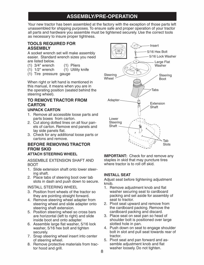
Your new tractor has been assembled at the factory with the exception of those parts left unassembled for shipping purposes. To ensure safe and proper operation of your tractor all parts and hardware you as sem ble must be tightened securely. Use the correct tools as nec es sary to in sure proper tightness.
ASSEMBLY/PRE-OPERATION
TOOLS REQUIRED FOR ASSEMBLYA socket wrench set will make assembly easier. Stan dard wrench sizes you need are listed below.(1) 3/4" wrench (1) Pliers(1) 1/2" wrench (1) Utility knife(1) Tire pressure gauge
When right or left hand is mentioned in this man ual, it means when you are in the operating po si tion (seated be hind the steer ing wheel).
TO REMOVE TRACTOR FROM CARTONUNPACK CARTON1. Remove all accessible loose parts and
parts boxes from carton.2. Cut along dotted lines on all four pan-
els of carton. Remove end panels and lay side panels fl at.
3. Check for any additional loose parts or cartons and remove.
INSTALL SEAT Adjust seat before tightening adjustment knob.1. Remove adjustment knob and fl at
washer securing seat to cardboard packing and set aside for assembly of seat to tractor.
2. Pivot seat upward and remove from the cardboard packing. Remove the cardboard packing and discard.
3. Place seat on seat pan so head of shoulder bolt is positioned over large slotted hole in pan.
4. Push down on seat to engage shoulder bolt in slot and pull seat towards rear of tractor.
5. Pivot seat and pan forward and as- sem ble adjustment knob and fl at washer loosely. Do not tighten.
0282
3
LowerSteering Shaft
Steering Boot
Extension Shaft
Steering Wheel
Insert
Adapter
5/16 Hex Bolt
Large Flat Washer
Tabs
TabSlots
5/16 Lock Washer
BEFORE REMOVING TRACTOR FROM SKIDATTACH STEERING WHEEL
ASSEMBLE EXTENSION SHAFT AND BOOT1. Slide extension shaft onto lower steer-
ing shaft. 2. Place tabs of steering boot over tab
slots in dash and push down to secure.
INSTALL STEERING WHEEL3. Position front wheels of the tractor so
they are pointing straight forward.4. Remove steering wheel adapter from
steering wheel and slide adapter onto steer ing shaft ex ten sion.
5. Position steering wheel so cross bars are hor i zon tal (left to right) and slide inside boot and onto adapt er.
6. Assemble large fl at washer, 5/16 lock washer, 5/16 hex bolt and tighten se cure ly.
7. Snap steering wheel insert into center of steer ing wheel.
8. Remove protective materials from trac- tor hood and grill.
IMPORTANT: Check for and remove any staples in skid that may puncture tires where tractor is to roll off skid.

9
TO ROLL TRACTOR OFF SKID (See Op er a tion section for location and function of con trols)1. Press lift lever plunger and raise
at tach ment lift lever to its highest po- si tion.
2. Release parking brake by depressing clutch/brake ped al.
3. Place gearshift lever in neutral (N) po si tion.
4. Roll tractor forward off skid.5. Remove banding holding defl ector
shield up against tractor.TO DRIVE TRACTOR OFF SKID (See Op er a tion section for location and func tion of con trols)
WARNING: Before starting, read, un- der stand and follow all in struc tions in the Operation section of this manual. Be sure tractor is in a well-ventilated area. Be sure the area in front of tractor is clear of other people and objects.1. Be sure all the above assembly steps
have been com plet ed.2. Check engine oil level and fi ll fuel tank
with gasoline.3. Sit on seat in operating position,
depress clutch/brake pedal and set the parking brake.
4. Place gear shift lever in neutral (N) position.
5. Press lift lever plunger and raise at tach ment lift lever to its highest posi-tion.
6. Start the engine. After engine has started, move throttle control to idle position.
7. Depress clutch/brake pedal into full "BRAKE" position and hold. Move gear-shift lever to 1st gear.
8. Slowly release clutch/brake pedal and slowly drive tractor off skid.
9. Apply brake to stop tractor, set park-ing brake and place gearshift lever in neutral position.
10.Turn ignition key to "STOP" position.Continue with the instructions that follow.
NOTE: You may now roll or drive your tractor off the skid. Follow the appropriate instruction below to remove the tractor from the skid.
6. Lower seat into operating position and sit in seat.
7. Slide seat until a comfortable position is reached which allows you to press clutch/brake pedal all the way down.
8. Get off seat without moving its ad- just ed position.
9. Raise seat and tighten adjustment knob securely.
2466
Seat Pan
Shoulder Bolt
Adjustment Knob
Flat Washer
Seat
02464
02173
Label
CHECK BATTERY1. Lift hood to raised position.NOTE: If this battery is put into service after month and year indicated on label (label located between terminals) charge battery for minimum of one hour at 6-10 amps. (See "BATTERY" in Maintenance section of this manual for charging instruc-tions).

10
CHECK TIRE PRESSUREThe tires on your tractor were over in -fl ated at the factory for shipping pur pos es. Correct tire pressure is important for best cutting performance.• Reduce tire pressure to PSI shown in
“PRODUCT SPEC I FI CA TIONS” section of this manual.
CHECK DECK LEVELNESSFor best cutting results, mower hous-ing should be properly leveled. See “TO LEVEL MOWER HOUSING” in the Service and Adjustments section of this manual.
CHECK FOR PROPER POSITION OF ALL BELTSSee the fi gures that are shown for replac-ing motion and mower blade drive belts in the Service and Adjustments sec tion of this manual. Verify that the belts are routed correctly.
CHECK BRAKE SYSTEMAfter you learn how to operate your trac-tor, check to see that the brake is properly adjusted. See “TO ADJUST BRAKE” in the Service and Adjustments section of this manual.
✓CHECKLISTBefore you operate and enjoy your new trac tor, we wish to assure that you receive the best per for mance and sat is fac tion from this Quality Prod uct.Please review the following checklist:✓ All assembly instructions have been
completed.✓ No remaining loose parts in carton.✓ Battery is properly prepared and
charged. (Minimum 1 hour at 6 amps).✓ Seat is adjusted comfortably and tight-
ened securely.✓ All tires are properly infl ated. (For ship-
ping purposes, the tires were overin-fl ated at the factory).
✓ Be sure mower deck is properly leveled side-to-side/front-to-rear for best cutting results. (Tires must be properly infl ated for leveling).
✓ Check mower and drive belts. Be sure they are routed properly around pulleys and inside all belt keepers.
✓ Check wiring. See that all con nec tions are still secure and wires are properly clamped.
While learning how to use your tractor, pay extra attention to the following important items:✓ Engine oil is at proper level.✓ Fuel tank is fi lled with fresh, clean, regu-
lar unleaded gasoline.✓ Become familiar with all controls - their
location and function. Operate them before you start the engine.
✓ Be sure brake system is in safe op er -at ing condition.
✓ Be sure Operator Presence System and Reverse Operation System (ROS) are working properly (See the Opera-tion and Maintenance sections in this manual).

11
OPERATION
These symbols may appear on your tractor or in literature supplied with the product. Learn and understand their meaning.
DANGER, KEEP HANDSAND FEET AWAY
FREE WHEEL(Automatic Models only)
OVER TEMPLIGHT
KEEP AREA CLEAR SLOPE HAZARDS
1515
(SEE SAFETY RULES SECTION)
BATTERY REVERSE FORWARD
FAST SLOW
ENGINE ONENGINE OFF
OIL PRESSUREFUEL
CHOKE
MOWER HEIGHT
PARKING BRAKELOCKED
PARKING BRAKEUNLOCKED
REVERSE NEUTRAL HIGH LOW
ATTACHMENTCLUTCH ENGAGED
PARKING BRAKE
IGNITION SWITCH
ATTACHMENTCLUTCH DISENGAGED
P
ENGINE START
MOWER LIFT
Failure to follow instructionscould result in serious injury ordeath. The safety alert symbolis used to identify safety inform-ation about hazards which canresult in death, serious injuryand/or property damage.
DANGER indicates a hazard which, if not avoided,will result in death or serious injury.
WARNING indicates a hazard which, if not avoided,could result in death or serious injury.
CAUTION indicates a hazard which, if not avoided,might result in minor or moderate injury.
CAUTION when used without the alert symbol,indicates a situation that could result in damageto the tractor and/or engine.
FIRE indicates a hazard which, if not avoided,could result in death, serious injury and/orproperty damage.
HOT SURFACES indicates a hazard which,if not avoided, could result in death, serious injuryand/or property damage.
REVERSEOPERATION
SYSTEM (ROS)
LIGHTS ON
12
KNOW YOUR TRACTORREAD THIS OWNER'S MANUAL AND SAFETY RULES BEFORE OPERATING YOUR TRACTORCompare the illustrations with your tractor to familiarize yourself with the locations of various controls and ad just ments. Save this manual for future reference.
Our tractors conform to the safety standards of the American National Stan dards Institute.
AMMETER - Indicates charging (+) or discharging (-) of battery.ATTACHMENT CLUTCH LEVER - Used to engage the mower blades, or other at-tachments mounted to your trac tor.ATTACHMENT LIFT LEVER - Used to raise, lower, and adjust the mower deck or other attachments mounted to your tractor.CLUTCH/BRAKE PEDAL - Used for declutching and brak ing the tractor and starting the engine.GEARSHIFT LEVER - Selects the speed and direction of tractor.IGNITION SWITCH - Used for starting and stopping the engine.
LIFT LEVER PLUNGER - Used to re lease attachment lift lever when chang ing its position.LIGHT SWITCH - Turns the headlights on and off.PARKING BRAKE LEVER - Locks clutch/brake pedal into the brake po si tion.REVERSE OPERATION SYSTEM (ROS) "ON" POSITION - Allows operation of mower deck or other powered attachment while in reverse.THROTTLE/CHOKE CONTROL - Used for starting and controlling engine speed.
02817_lsw
ROS "ON" Position
Lift Lever Plunger
Attachment Lift Lever
Parking Brake Lever
Gearshift Lever
Ignition SwitchAttachment Clutch LeverAmmeter
Throttle/Choke Control
Clutch/Brake Pedal
Height Adjustment Indicator
Light Switch
13
01844
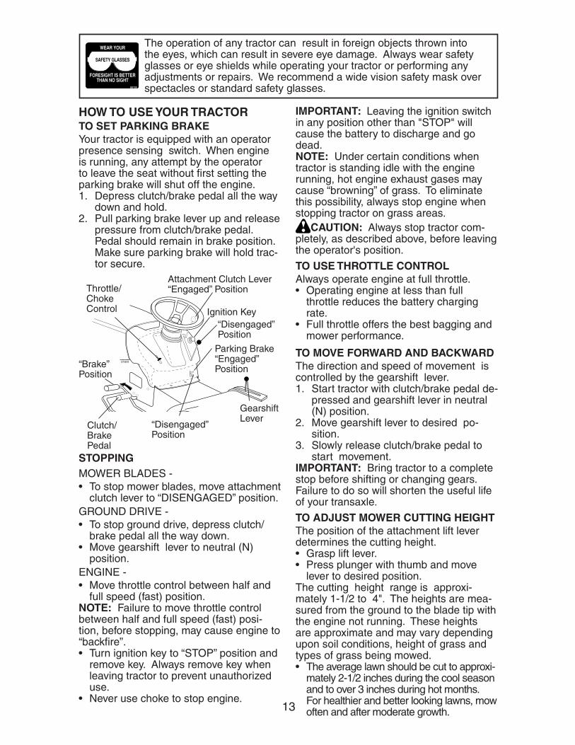
The op er a tion of any trac tor can result in foreign objects thrown into the eyes, which can result in severe eye dam age. Al ways wear safety glass es or eye shields while op er at ing your trac tor or per form ing any ad just ments or repairs. We rec om mend a wide vi sion safe ty mask over spec ta cles or stan dard safety glass es.00155
Attachment Clutch Lever “Engaged” Position
“Disengaged” Position
Gearshift Lever
“Brake” Position
Parking Brake “Engaged” Position
Clutch/Brake Pedal
“Disengaged” Position
STOPPINGMOWER BLADES -• To stop mower blades, move at tach ment
clutch lever to “DIS EN GAGED” po si tion.GROUND DRIVE -• To stop ground drive, depress clutch/
brake pedal all the way down.• Move gearshift lever to neutral (N)
po si tion.ENGINE - • Move throttle control between half and
full speed (fast) position.NOTE: Failure to move throttle control between half and full speed (fast) posi-tion, before stopping, may cause engine to “backfi re”.• Turn ignition key to “STOP” position and
remove key. Always remove key when leaving tractor to prevent un au tho rized use.
• Never use choke to stop engine.
IMPORTANT: Leaving the ignition switch in any position other than "STOP" will cause the battery to discharge and go dead.NOTE: Under certain conditions when tractor is standing idle with the engine running, hot engine exhaust gases may cause “browning” of grass. To elim i nate this possibility, always stop engine when stopping tractor on grass areas.
CAUTION: Always stop tractor com- plete ly, as de scribed above, before leav ing the operator's position.
TO USE THROTTLE CON TROL Always operate engine at full throttle.• Operating engine at less than full
throttle reduces the battery charg ing rate.
• Full throttle of fers the best bagging and mower per for mance.
Ignition Key
HOW TO USE YOUR TRAC TORTO SET PARKING BRAKE Your tractor is equipped with an operator presence sens ing switch. When engine is running, any attempt by the op er a tor to leave the seat without fi rst setting the parking brake will shut off the engine.1. Depress clutch/brake pedal all the way
down and hold.2. Pull parking brake lever up and re lease
pres sure from clutch/brake pedal. Pedal should re main in brake position. Make sure parking brake will hold trac-tor secure.
TO MOVE FORWARD AND BACK WARD The direction and speed of movement is controlled by the gearshift lever. 1. Start tractor with clutch/brake pedal de-
pressed and gearshift lever in neutral (N) position.
2. Move gearshift lever to desired po- si tion.
3. Slowly release clutch/brake pedal to start movement.
IMPORTANT: Bring tractor to a complete stop before shifting or changing gears. Failure to do so will shorten the useful life of your transaxle.
Throttle/ChokeControl
TO ADJUST MOWER CUT TING HEIGHTThe po si tion of the at tach ment lift le ver de ter mines the cut ting height.• Grasp lift le ver.• Press plunger with thumb and move
lever to desired position.The cutting height range is ap prox i- mate ly 1-1/2 to 4". The heights are mea-sured from the ground to the blade tip with the engine not running. These heights are approximate and may vary depending upon soil conditions, height of grass and types of grass being mowed.• The average lawn should be cut to approxi-
mately 2-1/2 inches during the cool season and to over 3 inches during hot months. For healthier and better looking lawns, mow often and after moderate growth.
14
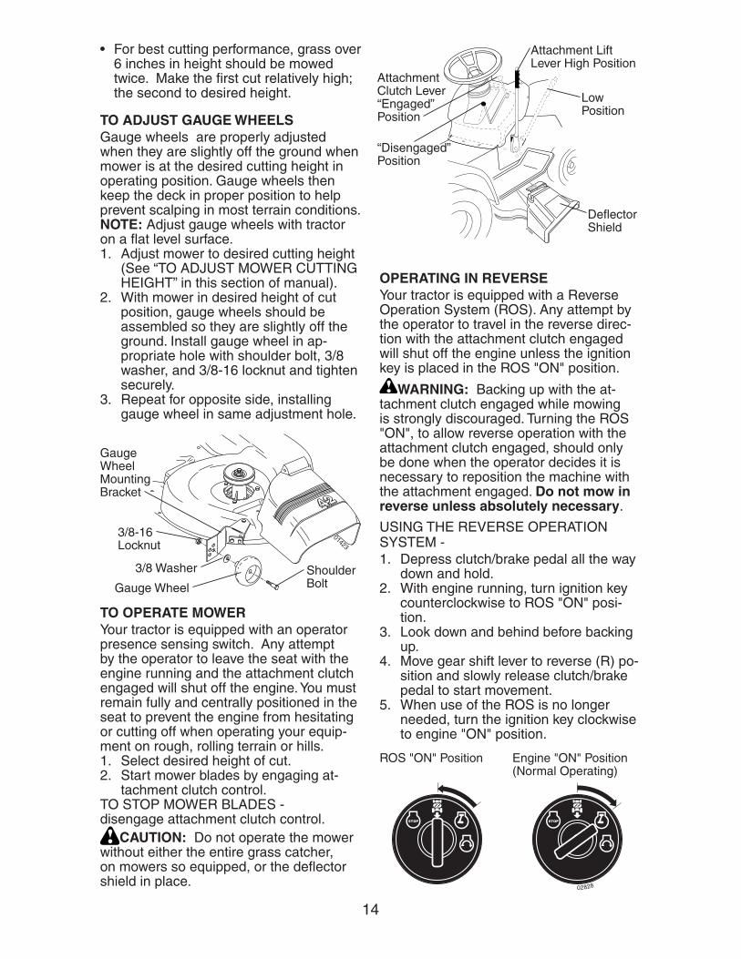
01994
Attachment Lift Lever High Position
Attachment Clutch Lever “Engaged” Position
“Disengaged” Position
Low Position
Defl ector Shield
TO OPERATE MOWERYour tractor is equipped with an operator presence sensing switch. Any attempt by the operator to leave the seat with the engine running and the attachment clutch engaged will shut off the engine. You must remain fully and centrally positioned in the seat to prevent the engine from hesitating or cutting off when operating your equip-ment on rough, rolling terrain or hills.1. Select desired height of cut.2. Start mower blades by engaging at-
tach ment clutch control.TO STOP MOWER BLADES - disengage at tach ment clutch con trol.
CAUTION: Do not operate the mower without either the en tire grass catcher, on mowers so equipped, or the defl ector shield in place.
01423
3/8 Washer
3/8-16 Locknut
Gauge Wheel MountingBracket
Shoulder BoltGauge Wheel
TO ADJUST GAUGE WHEELS Gauge wheels are prop er ly ad just ed when they are slight ly off the ground when mower is at the desired cutting height in operating position. Gauge wheels then keep the deck in proper position to help prevent scalping in most terrain conditions. NOTE: Adjust gauge wheels with tractor on a fl at level surface.1. Adjust mower to desired cutting height
(See “TO AD JUST MOWER CUT TING HEIGHT” in this sec tion of manual).
2. With mower in desired height of cut po si tion, gauge wheels should be assembled so they are slightly off the ground. In stall gauge wheel in ap- pro pri ate hole with shoulder bolt, 3/8 washer, and 3/8-16 locknut and tighten se cure ly.
3. Repeat for opposite side, installing gauge wheel in same adjustment hole.
• For best cutting performance, grass over 6 inches in height should be mowed twice. Make the fi rst cut relatively high; the second to de sired height.
02828
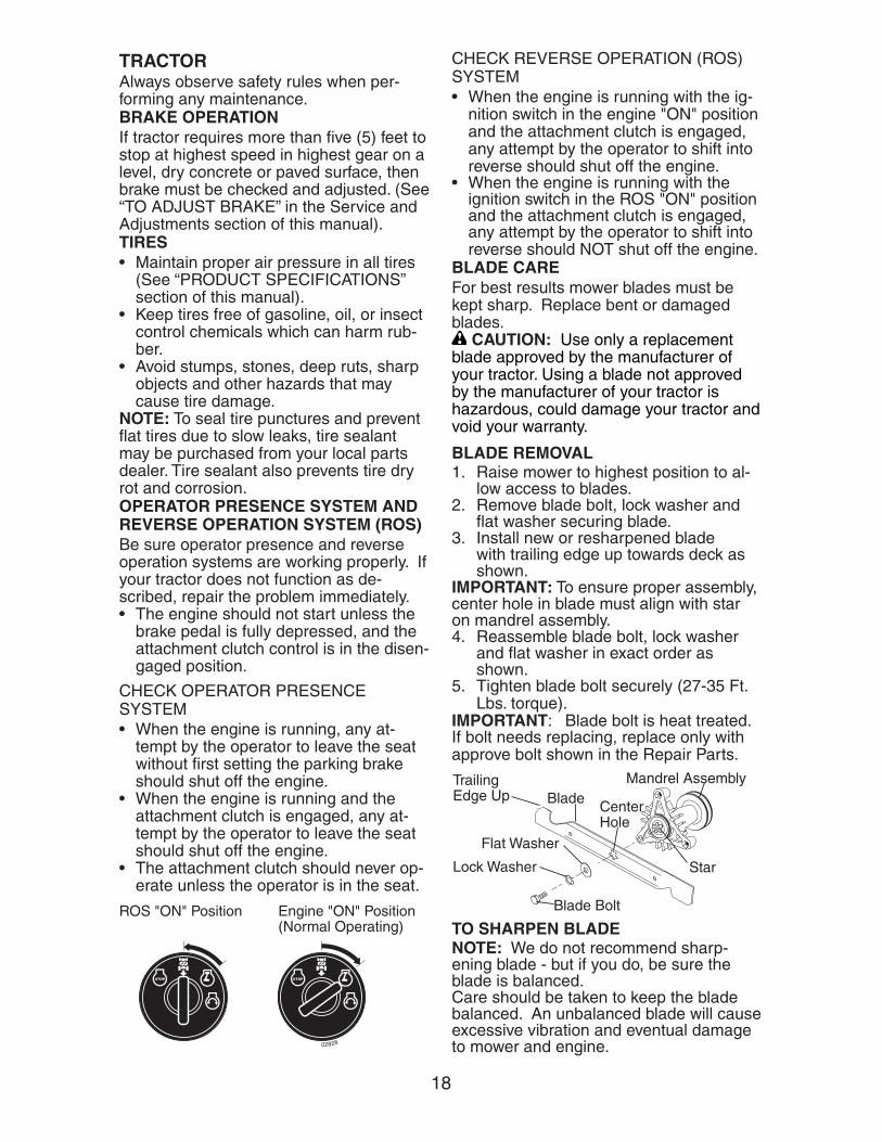
ROS "ON" Position Engine "ON" Position(Normal Operating)
OPERATING IN REVERSEYour tractor is equipped with a Reverse Operation System (ROS). Any attempt by the operator to travel in the reverse direc-tion with the attachment clutch engaged will shut off the engine unless the ignition key is placed in the ROS "ON" position.
WARNING: Backing up with the at-tachment clutch engaged while mowing is strongly discouraged. Turning the ROS "ON", to allow reverse operation with the attachment clutch engaged, should only be done when the operator decides it is necessary to reposition the machine with the attachment engaged. Do not mow in reverse unless absolutely necessary.
USING THE REVERSE OPERATION SYSTEM -1. Depress clutch/brake pedal all the way
down and hold.2. With engine running, turn ignition key
counterclockwise to ROS "ON" posi-tion.
3. Look down and behind before backing up.
4. Move gear shift lever to reverse (R) po- si tion and slowly release clutch/brake pedal to start movement.
5. When use of the ROS is no longer needed, turn the ignition key clockwise to engine "ON" position.
15
ADD GASOLINE • Fill fuel tank to bottom of fi ller neck. Do
not overfi ll. Use fresh, clean, regular un lead ed gasoline with a minimum of 87 octane. (Use of leaded gasoline will increase carbon and lead oxide deposits and reduce valve life). Do not mix oil with gasoline. Purchase fuel in quan- ti ties that can be used within 30 days to assure fuel freshness.CAUTION: Wipe off any spilled oil or
fuel. Do not store, spill or use gasoline near an open fl ame.IMPORTANT: When operating in temper-atures below32°F(0°C), use fresh, clean winter grade gas o line to help insure good cold weather start ing. CAUTION: Alcohol blended fuels (called gasohol or using ethanol or methanol) can attract moisture which leads to separa-tion and for ma tion of acids during storage. Acidic gas can damage the fuel system of an engine while in storage. To avoid engine problems, the fuel system should be emptied before stor age of 30 days or longer. Drain the gas tank, start the engine and let it run until the fuel lines and carburetor are empty. Use fresh fuel next season. See Storage In struc tions for additional information. Never use engine or carburetor cleaner products in the fuel tank or permanent damage may occur.
TOWING CARTS AND OTHER AT TACH -MENTSTow only the attachments that are rec om -mend ed by and comply with spec i fi ca tions of the manufacturer of your tractor. Use common sense when tow ing. Too heavy of a load, while on a slope, is dangerous. Tires can lose traction with the ground and cause you to lose control of your tractor.BEFORE STARTING THE ENGINECHECK ENGINE OIL LEVELThe engine in your tractor has been shipped, from the factory, already fi lled with sum mer weight oil. 1. Check engine oil with tractor on level
ground. 2. Remove oil fi ll cap/dipstick and wipe
clean, reinsert the dipstick and screw cap tight, wait for a few seconds, re-move and read oil level. If nec es sary, add oil until “FULL” mark on dipstick is reached. Do not overfi ll.
TO TRANSPORT• Raise attachment lift to highest position
with at tach ment lift control. • When pushing or towing your trac tor,
be sure gearshift lever is in neutral (N) position.
• Do not push or tow tractor at more than fi ve (5) MPH.
NOTE: To protect hood from damage when transporting your tractor on a truck or a trailer, be sure hood is closed and secured to tractor. Use an appropriate means of tying hood to tractor (rope, cord, etc.).
TO OPERATE ON HILLS
WARNING: Do not drive up or down hills with slopes great er than 15° and do not drive across any slope. Use the slope guide at the back of this manual.• Choose the slowest speed before start-
ing up or down hills.• Avoid stopping or changing speed on
hills.• If slowing is necessary, move throt tle
control lever to slower po si tion.• If stopping is absolutely necessary, push
clutch/brake pedal quickly to brake posi-tion and engage parking brake.
• Move gearshift lever to 1st gear. Be sure you have allowed room for tractor to roll slightly as you restart movement.
• To restart movement, slowly re lease parking brake and clutch/brake pedal.
• Make all turns slowly.
• For cold weather operation you should change oil for easier starting (See the oil viscosity chart in the Main te nance sec tion of this man u al).
• To change engine oil, see the Main te -nance section in this manual.
TO START ENGINEWhen starting the engine for the fi rst time or if the engine has run out of fuel, it will take extra cranking time to move fuel from the tank to the engine.1. Sit on seat in operating position,
depress clutch/brake pedal and set parking brake.
2. Place gear shift lever in neutral (N) position.
3. Move attachment clutch to dis en gaged po si tion.
4. Move throttle control to choke po si tion.NOTE: Before starting, read the warm and cold starting procedures below.

16
MOWING TIPS• Mower should be properly leveled for
best mowing performance. See “TO LEVEL MOWER HOUSING” in the Service and Adjustments section of this manual.
• The left hand side of mower should be used for trim ming.
• Drive so that clippings are dis charged onto the area that has already been cut. Have the cut area to the right of the tractor. This will result in a more even dis tri bu tion of clippings and more uniform cutting.
• When mowing large areas, start by turning to the right so that clippings will discharge away from shrubs, fences, driveways, etc. After one or two rounds, mow in the opposite direction making left hand turns until fi nished.
• If grass is extremely tall, it should be mowed twice to reduce load and pos-sible fi re hazard from dried clip pings. Make fi rst cut relatively high; the second to the desired height.
• Do not mow grass when it is wet. Wet grass will plug mower and leave undesirable clumps. Allow grass to dry before mowing.
• Always operate engine at full throt tle when mowing to assure better mowing performance and prop er dis charge of material. Reg u late ground speed by se lect ing a low enough gear to give the mower cut ting per for mance as well as the quality of cut desired.
• When operating attachments, se lect a ground speed that will suit the terrain and give best performance of the at- tach ment being used.
5. Insert key into ignition and turn key clockwise to start position and release key as soon as engine starts. Do not run starter continuously for more than fi fteen sec onds per minute. If the engine does not start after several attempts, move throt tle control to fast position, wait a few minutes and try again. If engine still does not start, move the throttle control back to the choke position and retry.
WARM WEATHER STARTING (50° F and above)6. When engine starts, move the throt tle
control to the fast position.• The attachments and ground drive can
now be used. If the engine does not accept the load, restart the en gine and allow it to warm up for one minute using the choke as de scribed above.
COLD WEATHER STARTING ( 50° F and below)6. When engine starts, leave throttle
control in choke position until engine warms up and begins to run roughly. Once rough running begins, im me -di ate ly move the throttle control to the fast position. Engine warm-up may take from several seconds to several minutes (the colder the tem per a ture, the longer the warm-up).
• The attachments can also be used dur-ing the engine warm-up period.
NOTE: If at a high altitude (above 3000 feet) or in cold temperatures (below 32 F) the carburetor fuel mixture may need to be adjusted for best engine performance (see “TO ADJUST CARBURETOR” in the Service and Adjustments section of this manual).

17
MAINTENANCE
BEFORE EACH USE
TRACT0R
Inspect Muffler/Spark Arrester
Lubrication Chart
Check Brake Operation
Clean Air Filter
Change Engine Oil (with oil filter)
Replace Air Filter Paper Cartridge
Replace Spark Plug
Check Battery Level
Check Tire Pressure
Clean Battery and Terminals
FILL IN DATESAS YOU COMPLETEREGULAR SERVICE
MAINTENANCE SCHEDULE
EVERY 8 HOURS
EVERY 25 HOURS
EVERY 50 HOURS
EVERY 100 HOURS
EVERY SEASON
SERVICE DATES
Check for Loose Fasteners
BEFORE STORAGE
Check Engine Oil Level
Clean Engine Cooling Fins
Sharpen/Replace Mower Blades
Check Operator Presence andROS Systems
Clean Air Screen
1 - Change more often when operating under a heavy load orin high ambient temperatures.
2 - Service more often when operating in dirty or dusty conditions.
ENGINE Replace Oil Filter (If equipped)
Check Transaxle Cooling
Check V-Belts
Replace Fuel Filter
3
2
2
2
2
3 - Replace blades more often when mowing in sandy soil.4 - Not required if equipped with maintenance-free battery.5 - Tighten front axle pivot bolt to 35 ft.-lbs. maximum.
Do not overtighten.
1,
1,2
2
4
5
Change Engine Oil (without oil filter) 1,2
maint_sch-tractore.new
1
LUBRICATION CHART
➀SAE 30 or 10w30 Motor Oil ➁General Purpose Grease➂Refer to Maintenance “ENGINE” Section
IMPORTANT: Do not oil or grease the pivot points which have special nylon bearings. Viscous lu bri cants will attract dust and dirt that will short en the life of the self-lu bri cat ing bearings. If you feel they must be lu bri cat ed, use only a dry, pow- dered graphite type lu bri cant spar ing ly.
01961
➁ Spindle Zerk
➁Front Wheel Bearing Zerk
➁Front Wheel Bearing Zerk
➂Engine
➀Gearshift Pivots
➁ SpindleZerk
GENERAL RECOMMENDATIONSThe warranty on this tractor does not cover items that have been subjected to operator abuse or negligence. To receive full value from the warranty, operator must main tain tractor as instructed in this manual.Some adjustments will need to be made periodically to properly maintain your tractor.At least once a season, check to see if you should make any of the adjustments described in the Service and Adjustments section of this manual.• At least once a year you should replace
the spark plug, clean or replace air fi lter, and check blades and belts for wear. A new spark plug and clean air fi lter assure proper air-fuel mixture and help your engine run better and last longer.
BEFORE EACH USE1. Check engine oil level.2. Check brake operation.3. Check tire pressure.4. Check operator presence and ROS systems for proper operation.5. Check for loose fasteners.
18
TRACTORAlways observe safety rules when per- form ing any main te nance.BRAKE OPERATIONIf tractor requires more than fi ve (5) feet to stop at highest speed in high est gear on a level, dry concrete or paved surface, then brake must be checked and ad just ed. (See “TO ADJUST BRAKE” in the Ser vice and Ad just ments section of this manual).TIRES• Maintain proper air pressure in all tires
(See “PROD UCT SPEC I FI CA TIONS” section of this man ual).
• Keep tires free of gasoline, oil, or insect control chemi cals which can harm rub-ber.
• Avoid stumps, stones, deep ruts, sharp objects and other hazards that may cause tire damage.
NOTE: To seal tire punctures and pre vent fl at tires due to slow leaks, tire sealant may be purchased from your local parts dealer. Tire sealant also prevents tire dry rot and corrosion.OPERATOR PRESENCE SYS TEM AND REVERSE OPERATION SYSTEM (ROS)Be sure operator presence and reverse operation sys tems are work ing properly. If your tractor does not function as de-scribed, repair the problem immediately.• The engine should not start unless the
brake pedal is fully de pressed, and the attachment clutch con trol is in the dis en -gaged position.
CHECK OPERATOR PRESENCE SYSTEM• When the engine is running, any at-
tempt by the op er a tor to leave the seat without fi rst setting the parking brake should shut off the engine.
• When the engine is running and the at tach ment clutch is engaged, any at-tempt by the operator to leave the seat should shut off the engine.
• The attachment clutch should never op-erate unless the operator is in the seat.
TO SHARPEN BLADE NOTE: We do not recommend sharp- en ing blade - but if you do, be sure the blade is balanced.Care should be taken to keep the blade balanced. An unbalanced blade will cause excessive vibration and even tual damage to mower and engine.
Blade Bolt
Mandrel AssemblyTrailing Edge Up
Flat Washer
Lock Washer
Center Hole
Blade
Star
BLADE REMOVAL 1. Raise mower to highest position to al-
low access to blades.2. Remove blade bolt, lock washer and
fl at washer securing blade.3. Install new or resharpened blade
with trailing edge up towards deck as shown.
IMPORTANT: To ensure proper as sem bly, center hole in blade must align with star on mandrel assembly.4. Reassemble blade bolt, lock washer
and fl at washer in exact order as shown.
5. Tighten blade bolt securely (27-35 Ft. Lbs. torque).
IMPORTANT: Blade bolt is heat treated. If bolt needs replacing, replace only with approve bolt shown in the Repair Parts.
CHECK REVERSE OPERATION (ROS) SYSTEM• When the engine is running with the ig-
nition switch in the engine "ON" position and the at tach ment clutch is engaged, any attempt by the operator to shift into reverse should shut off the engine.
• When the engine is running with the ignition switch in the ROS "ON" position and the at tach ment clutch is engaged, any attempt by the operator to shift into reverse should NOT shut off the engine.
BLADE CAREFor best results mower blades must be kept sharp. Re place bent or damaged blades.
CAUTION: Use only a replacement blade approved by the manufacturer of your tractor. Using a blade not approved by the manufacturer of your tractor is hazardous, could damage your tractor and void your warranty.
02828
ROS "ON" Position Engine "ON" Position(Normal Operating)
19
TRANSAXLE COOLINGKeep transaxle free from build-up of dirt and chaff which can restrict cooling.
V-BELTSCheck V-belts for deterioration and wear after 100 hours of operation and replace if necessary. The belts are not ad just able. Re place belts if they begin to slip from wear.
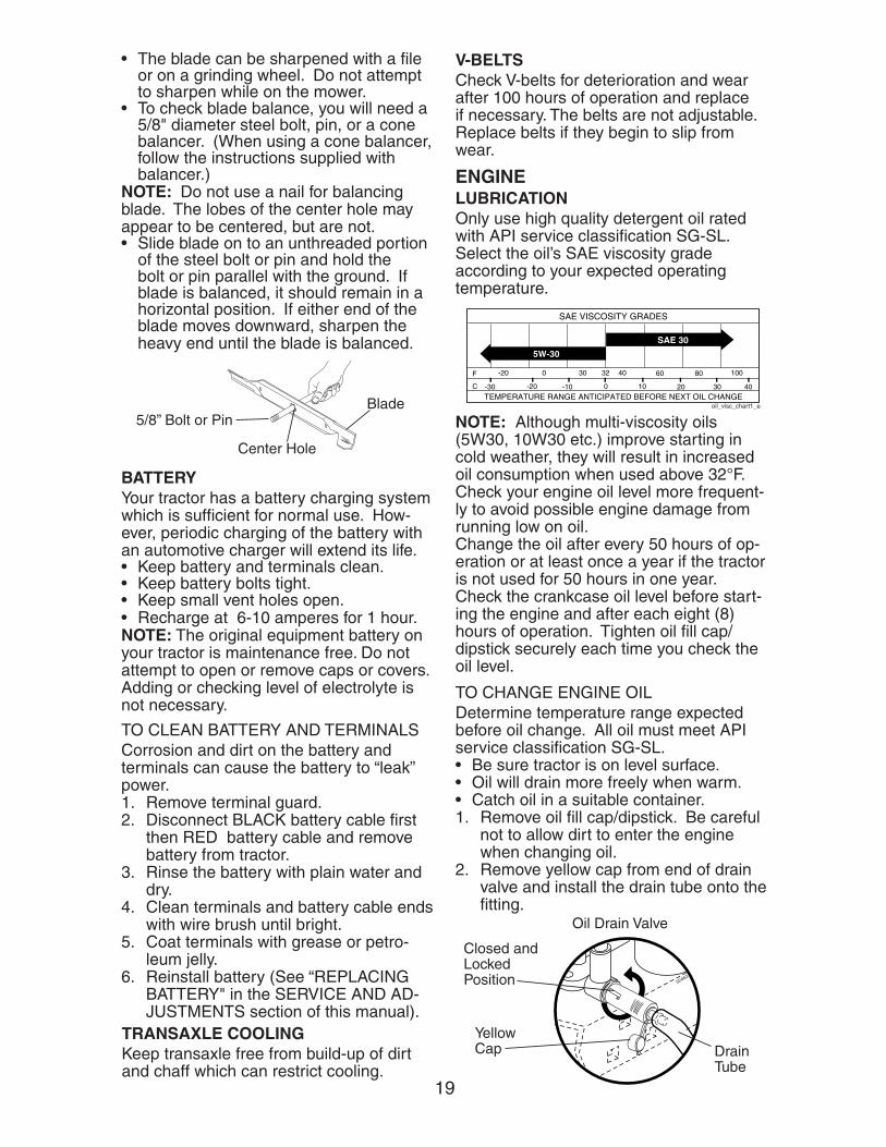
TEMPERATURE RANGE ANTICIPATED BEFORE NEXT OIL CHANGE
SAE VISCOSITY GRADES
-20 0 30 40 80 100
-30 -20 0 20 30 40
F
C
32
-10 10
60
5W-30
SAE 30
oil_visc_chart1_e
NOTE: Al though multi-vis cos i ty oils (5W30, 10W30 etc.) im prove start ing in cold weather, they will result in increased oil consumption when used above 32°F. Check your engine oil level more frequent-ly to avoid possible engine damage from running low on oil.Change the oil after every 50 hours of op-eration or at least once a year if the tractor is not used for 50 hours in one year.Check the crankcase oil level before start-ing the engine and after each eight (8) hours of operation. Tighten oil fi ll cap/dipstick securely each time you check the oil level.
ENGINELUBRICATIONOnly use high quality detergent oil rated with API service classifi cation SG-SL. Select the oil’s SAE viscosity grade according to your expected operating temperature.
TO CHANGE ENGINE OIL Determine temperature range expected before oil change. All oil must meet API service classifi cation SG-SL.• Be sure tractor is on level surface.• Oil will drain more freely when warm.• Catch oil in a suitable container.1. Remove oil fi ll cap/dipstick. Be careful
not to allow dirt to enter the engine when changing oil.
2. Remove yellow cap from end of drain valve and install the drain tube onto the fi tting.
02463
Closed and Locked Position
Oil Drain Valve
Yellow Cap Drain
Tube
BATTERYYour tractor has a battery charging sys tem which is suf fi cient for normal use. How- ev er, periodic charging of the battery with an automotive charger will extend its life.• Keep battery and terminals clean.• Keep battery bolts tight.• Keep small vent holes open.• Recharge at 6-10 amperes for 1 hour.NOTE: The original equipment battery on your tractor is maintenance free. Do not attempt to open or remove caps or cov ers. Adding or checking level of elec tro lyte is not necessary.
TO CLEAN BATTERY AND TER MI NALSCorrosion and dirt on the battery and terminals can cause the battery to “leak” power.1. Remove terminal guard.2. Disconnect BLACK battery cable fi rst
then RED bat tery cable and remove battery from tractor.
3. Rinse the battery with plain water and dry.
4. Clean terminals and battery cable ends with wire brush until bright.
5. Coat terminals with grease or pe tro -leum jelly.
6. Reinstall battery (See “REPLACING BATTERY" in the SERVICE AND AD- JUST MENTS section of this manual).
5/8” Bolt or Pin
Center Hole
Blade
• The blade can be sharpened with a fi le or on a grinding wheel. Do not attempt to sharpen while on the mower.
• To check blade balance, you will need a 5/8" diameter steel bolt, pin, or a cone balancer. (When using a cone bal anc er, follow the in struc tions supplied with bal anc er.)
NOTE: Do not use a nail for balancing blade. The lobes of the center hole may appear to be centered, but are not.• Slide blade on to an unthreaded portion
of the steel bolt or pin and hold the bolt or pin parallel with the ground. If blade is balanced, it should remain in a horizontal po si tion. If either end of the blade moves downward, sharpen the heavy end until the blade is balanced.

20
AIR FILTERYour engine will not run properly using a dirty air fi lter. Replace pre-cleaner after every 25 hours of operation or every season. Service paper cartridge every 100 hours of operation or every season, whichever occurs fi rst.Service air cleaner more often under dusty conditions.1. Pull up on air fi lter cover handle and
rotate towards engine.2. Remove cover.3. Carefully remove air fi lter cartridge and
pre-cleaner from base.4. Clean base carefully to prevent debris
from falling into carburetor.NOTE: If very dirty or damaged, replace cartridge.5. Place new pre-cleaner and cartridge
fi rmly in base.6. Align tabs on cover with slots in blower
housing and replace cover.7. Hook handle on cover and push down
on handle to close. IMPORTANT: Petroleum solvents, such as kerosene, are not to be used to clean the cartridge. They may cause de te ri o -ra tion of the cartridge. Do not oil car-tridge. Do not use pressurized air to clean cartridge. 00667
Fuel FilterClamp
Clamp
MUFFLER Inspect and replace corroded muffl er and spark arrester (if equipped) as it could cre-ate a fi re hazard and/or dam age.SPARK PLUG(S) Replace spark plug(s) at the beginning of each mowing season or after every 100 hours of operation, whichever occurs fi rst. Spark plug type and gap setting are shown in “PROD UCT SPEC I FI CA TIONS” section of this manual.IN-LINE FUEL FILTER The fuel fi lter should be replaced once each season. If fuel fi lter becomes clogged, ob struct ing fuel fl ow to car bu -re tor, re place ment is re quired.1. With engine cool, remove fi lter and
plug fuel line sec tions.2. Place new fuel fi lter in position in fuel
line with arrow pointing towards carbu-retor.
3. Be sure there are no fuel line leaks and clamps are properly positioned.
4. Immediately wipe up any spilled gaso-line.
CLEAN AIR SCREENAir screen must be kept free of dirt and chaff to prevent engine dam age from overheating. Clean with a wire brush or compressed air to re move dirt and stub- born dried gum fi bers.
SlotsTabsBase
Cartridge
Pre-cleaner
Cover
02698
Handle
02744
ENGINE COOLING SYSTEM Debris may clog the engine’s air cool-ing system. Remove blower housing and clean area shown to prevent overheating and engine damage.
Clean out chaffand debrisAir Screen
ENGINE OIL FILTERReplace the engine oil fi lter every sea son or every other oil change if the tractor is used more than 100 hours in one year.
3. Un lock drain valve by pushing inward slightly and turning counterclockwise.
4. To open, pull out on the drain valve.5. After oil has drained completely, close
and lock the drain valve by pushing inward and turning clock wise until the pin is in the locked position as shown.
6. Remove the drain tube and replace the cap onto the end of the drain valve.
7. Refi ll engine with oil through oil fi ll dip-stick tube. Pour slowly. Do not overfi ll. For approximate capacity see “PROD-UCT SPEC I FI CA TIONS” section of this man u al.
8. Use gauge on oil fi ll cap/dipstick for checking level. For accurate reading, tighten dipstick cap securely onto the tube before removing dipstick. Keep oil at “FULL” line on dipstick. Tighten cap onto the tube securely when fi nished.
21
02696
CLEANING• Clean engine, battery, seat, fi nish, etc.
of all foreign matter.• Keep fi nished surfaces and wheels free
of all gasoline, oil, etc.• Protect painted surfaces with au to -
mo tive type wax.
SERVICE AND ADJUSTMENTS
WARNING: TO AVOID SERIOUS INJURY, BEFORE PERFORMING ANY SER VICE OR AD JUST MENTS:1. Depress clutch/brake pedal fully and set parking brake.2. Place gearshift lever in neutral (N) position.3. Place attachment clutch in “DISENGAGED” position.4. Turn ignition key to “STOP” and remove key.5. Make sure the blades and all moving parts have completely stopped.6. Disconnect spark plug wire from spark plug and place wire where it cannot
come in contact with plug.
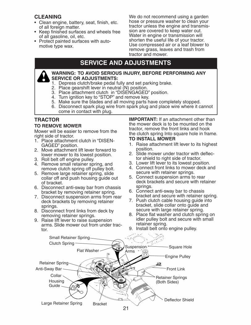
TRACTORTO REMOVE MOWERMower will be easier to remove from the right side of tractor.1. Place attachment clutch in “DIS EN-
GAGED” position.2. Move attachment lift lever forward to
low er mower to its lowest po si tion.3. Roll belt off engine pulley.4. Remove small retainer spring, and
remove clutch spring off pulley bolt.5. Remove large retainer spring, slide
col lar off and push housing guide out of brack et.
6. Disconnect anti-sway bar from chas sis bracket by re mov ing re tain er spring.
7. Disconnect suspension arms from rear deck brackets by removing retainer springs.
8. Disconnect front links from deck by re mov ing retainer springs.
9. Raise lift lever to raise suspension arms. Slide mower out from under trac-tor.
IMPORTANT: If an attachment other than the mower deck is to be mounted on the trac tor, remove the front links and hook the clutch spring Into square hole in frame.TO INSTALL MOWER1. Raise attachment lift lever to its high est
position.2. Slide mower under tractor with defl ec-
tor shield to right side of tractor.3. Lower lift lever to its lowest po si tion.4. Connect front links to mower deck and
secure with retainer springs.5. Connect suspension arms to rear
deck brackets and secure with retainer springs.
6. Connect anti-sway bar to chassis bracket and secure with retainer spring.
7. Push clutch cable housing guide into bracket, slide collar onto guide and secure with large retainer spring.
8. Place fl at washer and clutch spring on idler pulley bolt and secure with small retainer spring.
9. Install belt onto engine pulley.
Suspension Arms
Retainer SpringAnti-Sway Bar
Housing Guide
Collar
Large Re tain er Spring
Clutch SpringSmall Retainer Spring
Bracket
Retainer Springs(Both Sides)
Front Link
Engine Pulley
Square Hole
Defl ector Shield
Flat Washer
We do not recommend using a garden hose or pressure washer to clean your tractor unless the engine and transmis-sion are covered to keep water out. Water in engine or transmission will shorten the useful life of your tractor. Use compressed air or a leaf blower to remove grass, leaves and trash from tractor and mower.

22
01156
00598
01267
Both Front Links Should be Equal in Length
Nut “F”Ground Line
Bottom edge of mower to ground
01553
Suspension Arm
Lift Link Adjustment Nut
01268
Bottom edge of mower to ground
AA
Trunnion
Front Links
Nut “E”
“D” “D”
Mandrel
TO LEVEL MOWER HOUSINGAdjust the mower while tractor is parked on level ground or driveway. Make sure tires are properly infl ated (See “PROD- UCT SPECIFICATIONS” section of this man u al). If tires are over or underinfl ated, you will not properly adjust your mower.SIDE-TO-SIDE ADJUSTMENT • Raise mower to its highest position.• At the midpoint of both sides of mower,
measure height from bot tom edge of mower to ground. Distance “A” on both sides of mower should be the same or within 1/4" of each other.
• If adjustment is necessary, make adjust-ment on one side of mower only.
• To raise one side of mower, tighten lift link ad just ment nut on that side.
• To lower one side of mower, loosen lift link ad just ment nut on that side.
NOTE: Each full turn of adjustment nut will change mower height about 1/8".• Recheck measurements after ad just ing.
TO REPLACE MOWER BLADE DRIVE BELT The mower blade drive belt may be re-placed without tools. Park the tractor on level surface. Engage parking brake.
BELT REMOVAL -1. Remove mower from tractor (See “TO
REMOVE MOW ER” in this sec tion of manual).
2. Work belt off both mandrel pulleys and idler pulleys.
3. Pull belt away from mower.
BELT INSTALLATION -1. Work belt around both mandrel pulleys
and idler pulleys2. Make sure belt is in all pulley grooves
and inside all belt guides.3. Install mower (See “To Install Mower” in
this section of this manual).
FRONT-TO-BACK ADJUSTMENT IMPORTANT: Deck must be level side-to side. If the following front-to-back ad just -ment is necessary, be sure to adjust both front links equally so mower will stay level side-to-side. To obtain the best cutting results, the mower housing should be adjusted so that the front is approximately 1/8" to 1/2" lower than the rear when the mower is in its highest position.Check adjustment on right side of trac- tor. Measure dis tance “D” directly in front and behind the mandrel at bottom edge of mower housing as shown.• Before making any necessary ad just -
ments, check that both front links are equal in length.
• If links are not equal in length, adjust one link to same length as other link.
• To lower front of mower loosen nut “E” on both front links an equal number of turns.
• When distance “D” is 1/8" to 1/2" lower at front than rear, tighten nuts “F” against trunnion on both front links.
• To raise front of mower, loos en nut “F” from trunnion on both front links. Tighten nut “E” on both front links an equal num-ber of turns. The two front links must remain equal in length.
• When distance “D” is 1/8" to 1/2" lower at front than rear, tighten nut “F” against trun nion on both front links.
• Recheck side-to-side ad just ment.
23
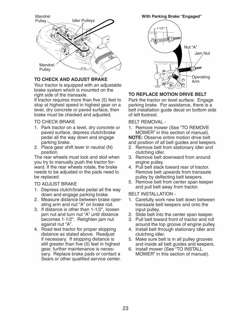
02314
MandrelPulley
Mandrel Pulley
Idler Pulleys
TO CHECK AND ADJUST BRAKE Your tractor is equipped with an ad just able brake system which is mounted on the right side of the transaxle.If tractor requires more than fi ve (5) feet to stop at highest speed in high est gear on a level, dry concrete or paved surface, then brake must be checked and ad just ed.
TO CHECK BRAKE1. Park tractor on a level, dry concrete or
paved surface, depress clutch/brake pedal all the way down and engage parking brake.
2. Place gear shift lever in neutral (N) position.
The rear wheels must lock and skid when you try to manually push the tractor for-ward. If the rear wheels rotate, the brake needs to be adjusted or the pads need to be replaced.
TO ADJUST BRAKE1. Depress clutch/brake pedal all the way
down and en gage parking brake.2. Measure distance between brake op er -
at ing arm and nut “A” on brake rod.3. If distance is other than 1-1/2", loos en
jam nut and turn nut “A” until dis tance becomes 1-1/2". Re tight en jam nut against nut “A”.
4. Road test tractor for proper stopping distance as stated above. Readjust if nec es sary. If stopping distance is still greater than fi ve (5) feet in high est gear, further main te nance is nec es -sary. Replace brake pads or contact a Sears or other qualifi ed service center.
1-1/2"
00238
Jam Nut
With Parking Brake “Engaged”
Operating Arm
Nut “A”
TO REPLACE MOTION DRIVE BELTPark the tractor on level surface. En gage parking brake. For as sis tance, there is a belt installation guide decal on bottom side of left footrest.
BELT REMOVAL -1. Remove mower (See “TO RE MOVE
MOWER” in this section of manual).NOTE: Observe entire motion drive belt and position of all belt guides and keepers.2. Remove belt from stationary idler and
clutching idler.3. Remove belt downward from around
en gine pulley.4. Pull belt slack toward rear of trac tor.
Remove belt upwards from transaxle pulley by de fl ect ing belt keepers.
5. Remove belt from center span keeper and pull belt away from tractor.
BELT INSTALLATION -1. Carefully work new belt down be tween
transaxle belt keepers and onto the input pulley.
2. Slide belt into the center span keeper.3. Pull belt toward front of tractor and roll
around the top groove of engine pulley.4. Install belt through stationary idler and
clutch ing idler.5. Make sure belt is in all pulley grooves
and in side all belt guides and keep ers.6. Install mower (See “TO IN STALL
MOWER” in this sec tion of manual).
24
TO AD JUST STEER ING WHEEL ALIGN- MENTIf steering wheel crossbars are not hor i zon tal (left to right) when wheels are positioned straight forward, remove steer- ing wheel and reassemble with crossbars horizontal. Tighten securely.
FRONT WHEEL TOE-IN/CAM BERThe front wheel toe-in and camber are not adjustable on your tractor. If dam age has occurred to affect the front wheel toe-in or camber, contact a Sears or other qualifi ed service center.
00663
Retaining Ring
Washers
Square Key(Rear Wheel Only)
Axle Cover
02239 Adjustment Bolt
Neutral Lock GateGearshift Lever
TRANSAXLE GEAR SHIFT LEVER NEU-TRAL ADJUSTMENTThe transaxle should be in neutral when the gear shift lever is in neutral (N) (lock gate) position. The adjustment is preset at the factory; however, if adjustment is needed, proceed as follows:1. Make sure transaxle is in neutral (N).NOTE: When the tractor rear wheels move freely, the transaxle is in neu tral.2. Loosen adjustment bolt in front of the
right rear wheel.3. Position the gear shift lever in the neu-
tral (N) position.4. Tighten adjustment bolt securely.NOTE: If additional clearance is needed to get to ad just ment bolt, move mower deck height to the lowest position.
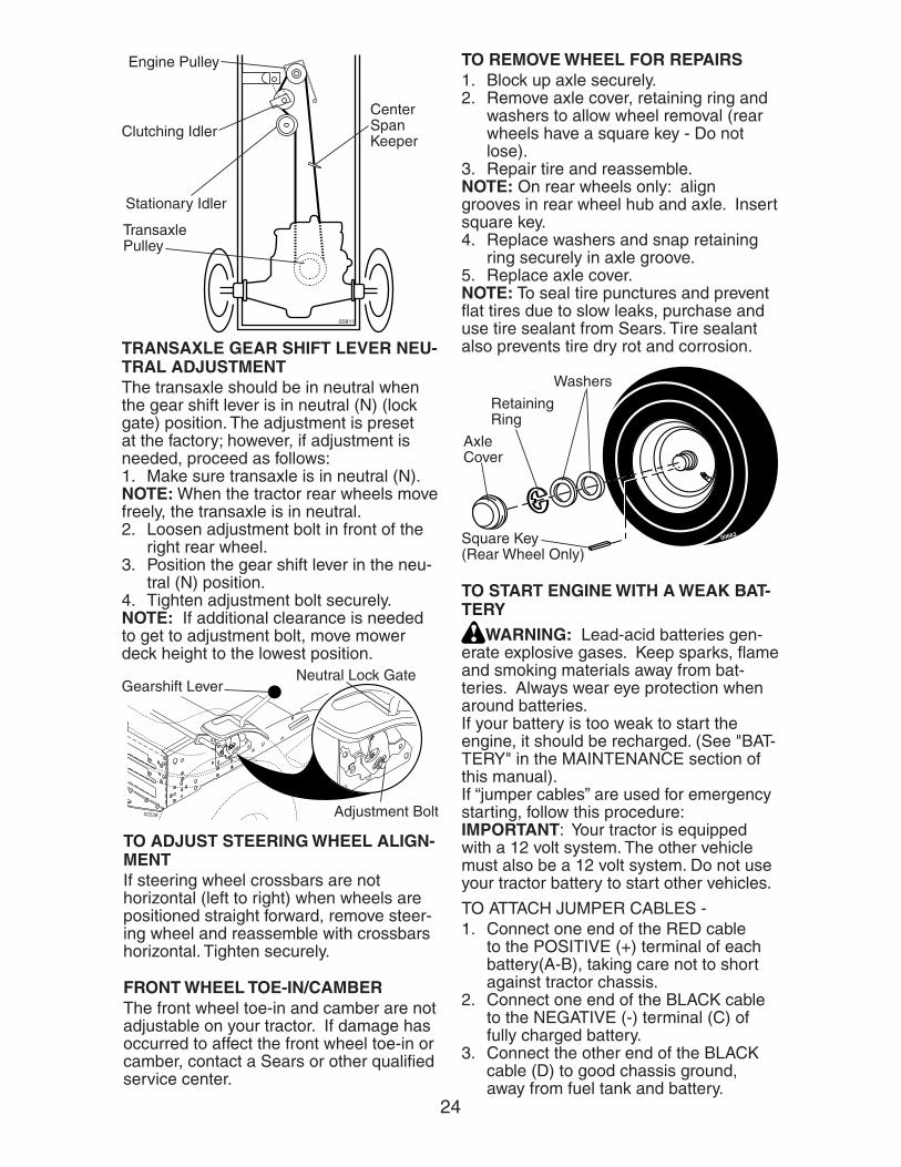
TO REMOVE WHEEL FOR REPAIRS 1. Block up axle securely.2. Remove axle cover, retaining ring and
washers to allow wheel removal (rear wheels have a square key - Do not lose).
3. Repair tire and reassemble.NOTE: On rear wheels only: align grooves in rear wheel hub and axle. Insert square key.4. Replace washers and snap retaining
ring securely in axle groove.5. Replace axle cover.NOTE: To seal tire punctures and pre vent fl at tires due to slow leaks, purchase and use tire sealant from Sears. Tire sealant also pre vents tire dry rot and corrosion.
TO START ENGINE WITH A WEAK BAT- TERY
WARNING: Lead-acid batteries gen- er ate ex plo sive gases. Keep sparks, fl ame and smoking ma te ri als away from bat- ter ies. Always wear eye pro tec tion when around batteries.If your battery is too weak to start the engine, it should be recharged. (See "BAT-TERY" in the MAINTENANCE section of this man u al).If “jumper ca bles” are used for emer gen cy starting, follow this pro ce dure:IMPORTANT: Your tractor is equipped with a 12 volt system. The other vehicle must also be a 12 volt system. Do not use your tractor battery to start other vehicles.
TO ATTACH JUMPER CABLES -1. Connect one end of the RED cable
to the POSITIVE (+) terminal of each battery(A-B), taking care not to short against tractor chassis.
2. Connect one end of the BLACK ca ble to the NEGA TIVE (-) terminal (C) of fully charged battery.
3. Connect the other end of the BLACK cable (D) to good chassis ground, away from fuel tank and bat tery.
00811
Transaxle Pulley
Stationary Idler
Clutching Idler
Engine Pulley
Center Span Keeper
25
02495
Hood
Headlight Wire Connector
TO REPLACE HEADLIGHT BULB1. Raise hood.2. Pull bulb holder out of the hole in the
backside of the grill.3. Replace bulb in holder and push bulb
holder securely back into the hole in the backside of the grill.
4. Close hood.
TO REMOVE HOOD AND GRILL AS-SEMBLY 1. Raise hood.2. Unsnap headlight wire connector.3. Stand in front of tractor. Grasp hood at
sides, tilt toward engine and lift off of tractor.
4. When replacing hood, be sure to re-connect the headlight wire con nec tor.
INTERLOCKS AND RELAYSLoose or damaged wiring may cause your tractor to run poorly, stop running, or prevent it from starting.• Check wiring. See electrical wiring
diagram in the Repair Parts section.TO REPLACE FUSEReplace with 20 amp automotive-type plug-in fuse. The fuse holder is located behind the dash.
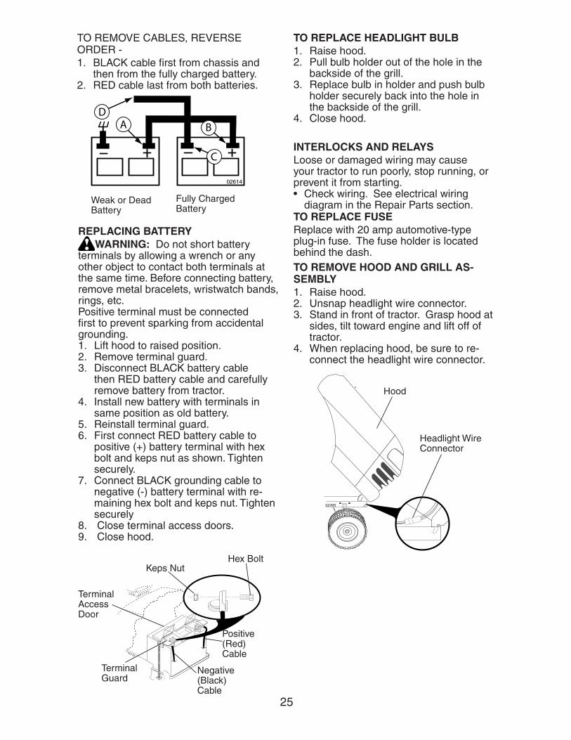
02614
Weak or DeadBattery
Fully ChargedBattery
TO REMOVE CABLES, REVERSE ORDER -1. BLACK cable fi rst from chassis and
then from the fully charged battery.2. RED cable last from both batteries.
02179
Keps Nut
Terminal Guard
Terminal Access Door
Hex Bolt
Positive (Red) Cable
Negative (Black) Cable
REPLACING BATTERY WARNING: Do not short battery
ter mi nals by allowing a wrench or any other object to contact both terminals at the same time. Before connecting battery, remove metal bracelets, wristwatch bands, rings, etc.Positive terminal must be connected fi rst to prevent sparking from ac ci den tal grounding.1. Lift hood to raised position.2. Remove terminal guard.3. Disconnect BLACK battery cable
then RED battery cable and carefully remove battery from tractor.
4. Install new battery with terminals in same position as old battery.
5. Reinstall terminal guard.6. First connect RED battery cable to
positive (+) battery terminal with hex bolt and keps nut as shown. Tighten securely.
7. Connect BLACK grounding cable to negative (-) bat tery terminal with re- main ing hex bolt and keps nut. Tight en securely
8. Close terminal access doors.9. Close hood.
26
01915
Idle SpeedScrew
Throttle Lever
Idle Mixture Valve With Limiter
01041
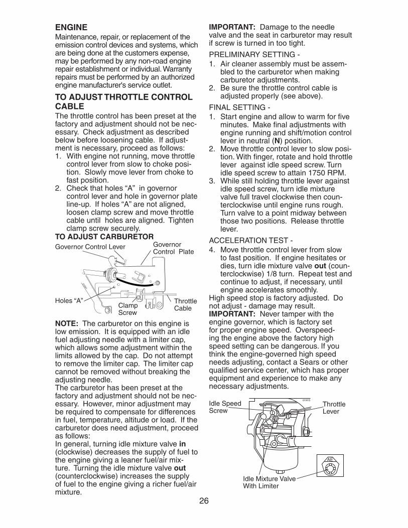
Governor Control Lever Governor Control Plate
Throttle Cable
Holes “A”Clamp Screw
ENGINEMaintenance, re pair, or re place ment of the emission con trol de vic es and sys tems, which are be ing done at the cus tom ers expense, may be performed by any non-road engine repair es tab lish ment or individual. Warranty repairs must be performed by an authorized engine man u fac tur er's service outlet.
TO AD JUST THROTTLE CON TROL CABLEThe throttle control has been preset at the factory and ad just ment should not be nec-essary. Check adjustment as de scribed below before loosening cable. If adjust-ment is necessary, proceed as follows:1. With engine not running, move throt tle
control lever from slow to choke posi-tion. Slowly move lever from choke to fast position.
2. Check that holes “A” in governor control lever and hole in governor plate line-up. If holes “A” are not aligned, loosen clamp screw and move throttle cable until holes are aligned. Tighten clamp screw securely.
TO AD JUST CARBURETOR
NOTE: The carburetor on this engine is low emission. It is equipped with an idle fuel adjusting needle with a limiter cap, which allows some adjustment within the limits al lowed by the cap. Do not attempt to remove the limiter cap. The limiter cap cannot be removed without breaking the adjusting needle. The carburetor has been preset at the factory and ad just ment should not be nec-essary. However, minor ad just ment may be required to compensate for dif fer enc es in fuel, tem per a ture, altitude or load. If the carburetor does need ad just ment, proceed as follows:In general, turning idle mixture valve in (clock wise) de creases the supply of fuel to the engine giving a leaner fuel/air mix-ture. Turning the idle mixture valve out (counter clock wise) in creases the sup ply of fuel to the engine giving a richer fuel/air mixture.
IMPORTANT: Damage to the needle valve and the seat in carburetor may result if screw is turned in too tight.
PRELIMINARY SETTING -1. Air cleaner assembly must be as sem -
bled to the car bu re tor when making carburetor adjustments.
2. Be sure the throttle control cable is adjusted properly (see above).
FINAL SETTING -1. Start engine and allow to warm for fi ve
minutes. Make fi nal ad just ments with engine running and shift/motion control lever in neutral (N) position.
2. Move throttle control lever to slow posi-tion. With fi nger, rotate and hold throttle lever against idle speed screw. Turn idle speed screw to attain 1750 RPM.
3. While still holding throttle lever against idle speed screw, turn idle mix ture valve full travel clockwise then coun- ter clock wise until engine runs rough. Turn valve to a point midway be tween those two po si tions. Re lease throt tle lever.
ACCELERATION TEST -4. Move throttle control lever from slow
to fast po si tion. If engine hesitates or dies, turn idle mixture valve out (coun-ter clock wise) 1/8 turn. Repeat test and continue to adjust, if nec es sary, until engine ac cel er ates smooth ly.
High speed stop is factory adjusted. Do not adjust - damage may result. IMPORTANT: Never tamper with the engine governor, which is factory set for proper engine speed. Overspeed-ing the engine above the factory high speed setting can be dangerous. If you think the engine-governed high speed needs adjusting, contact a Sears or other qualifi ed service center, which has proper equip ment and ex pe ri ence to make any nec es sary ad just ments.
27
STORAGE
Immediately prepare your tractor for stor- age at the end of the season or if the trac-tor will not be used for 30 days or more.
CAUTION: Never store the trac tor with gas o line in the tank inside a building where fumes may reach an open fl ame or spark. Allow the engine to cool before storing in any en clo sure.
TRACTORRemove mower from tractor for winter storage. When mower is to be stored for a period of time, clean it thor oughly, remove all dirt, grease, leaves, etc. Store in a clean, dry area.1. Clean entire tractor (See “CLEAN ING”
in the Maintenance section of this manual).
2. Inspect and replace belts, if nec es sary (See belt re place ment in struc tions in the Service and Ad just ments section of this manual).
3. Lubricate as shown in the Main te nance section of this man ual.
4. Be sure that all nuts, bolts and screws are securely fastened. In spect moving parts for damage, break age and wear. Replace if nec es sary.
5. Touch up all rusted or chipped paint surfaces; sand lightly before paint ing.
BATTERY• Fully charge the battery for storage.• After a period of time in storage, battery
may require recharging.• To help prevent corrosion and power
leakage during long periods of stor age, battery cables should be dis con nect ed and battery cleaned thor ough ly (see “TO CLEAN BATTERY AND TER MI NALS” in the Maintenance section of this man u al).
• After cleaning, leave cables dis con -nect ed and place cables where they cannot come in contact with battery terminals.
• If battery is removed from tractor for storage, do not store battery directly on concrete or damp surfaces.
ENGINEFUEL SYSTEMIMPORTANT: It is important to prevent gum deposits from forming in essential fuel system parts such as carburetor, fuel hose, or tank during storage. Also, alcohol
blended fuels (called gasohol or using ethanol or methanol) can attract moisture which leads to separation and formation of acids during storage. Acidic gas can dam-age the fuel system of an engine while in storage.• Empty the fuel tank by starting the en-
gine and letting it run until the fuel lines and carburetor are empty.
• Never use engine or carburetor clean er products in the fuel tank or permanent damage may occur.
• Use fresh fuel next season.NOTE: Fuel stabilizer is an acceptable alternative in min i miz ing the formation of fuel gum deposits during stor age. Add stabilizer to gasoline in fuel tank or stor- age container. Always follow the mix ratio found on stabilizer container. Run engine at least 10 minutes after adding stabilizer to allow the sta bi liz er to reach the car-buretor. Do not empty the gas tank and carburetor if using fuel stabilizer.ENGINE OILDrain oil (with engine warm) and replace with clean engine oil. (See “ENGINE” in the Maintenance section of this man ual).CYLINDER(S)1. Remove spark plug(s).2. Pour one ounce of oil through spark
plug hole(s) into cylinder(s).3. Turn ignition key to “START” po si tion
for a few seconds to distribute oil.4. Replace with new spark plug(s).
OTHER• Do not store gasoline from one sea son
to another.• Replace your gasoline can if your can
starts to rust. Rust and/or dirt in your gasoline will cause problems.
• If possible, store your tractor in doors and cover it to give protection from dust and dirt.
• Cover your tractor with a suitable pro-tective cover that does not retain mois-ture. Do not use plastic. Plas tic cannot breathe which allows con den sa tion to form and will cause your tractor to rust.
IMPORTANT: Never cover tractor while en gine and exhaust areas are still warm.
28
Will not start 1. Out of fuel. 1. Fill fuel tank. 2. Engine not “CHOKED” 2. See “TO START ENGINE” properly. in Operation section. 3. Engine fl ooded. 3. Wait several minutes before attempting to start. 4. Bad spark plug. 4. Replace spark plug. 5. Dirty air fi lter. 5. Clean/replace air fi lter. 6. Dirty fuel fi lter. 6. Replace fuel fi lter. 7 Water in fuel. 7. Empty fuel tank and carbure- tor, refi ll tank with fresh gas- oline and replace fuel fi lter. 8. Loose or damaged wiring. 8. Check all wiring. 9. Carburetor out of adjustment. 9. See “To Adjust Car bu re tor” in Service and Adjustments section. 10.Engine valves out of 10.Contact a Sears or other adjustment. qualifi ed service center.
Hard to start 1. Dirty air fi lter. 1. Clean/replace air fi lter. 2. Bad spark plug. 2. Replace spark plug. 3. Weak or dead battery. 3. Recharge or replace battery. 4. Dirty fuel fi lter. 4. Replace fuel fi lter. 5. Stale or dirty fuel. 5. Empty fuel tank and refi ll tank with fresh, clean gasoline. 6. Loose or damaged wiring. 6. Check all wiring. 7. Carburetor out of adjustment. 7. See “To Adjust Car bu re tor” in Service and Adjustments section. 8. Engine valves out of 8. Contact a Sears or other adjustment. qualifi ed service center.
Engine will not 1. Clutch/brake pedal not 1. Depress clutch/brake pedal. turn over depressed. 2. Attachment clutch is engaged. 2. Disengage at tach ment clutch. 3. Weak or dead battery. 3. Recharge or replace battery. 4. Blown fuse. 4. Replace fuse. 5. Corroded battery terminals. 5. Clean battery terminals. 6. Loose or damaged wiring. 6. Check all wiring. 7. Faulty ignition switch. 7. Check/replace ignition switch. 8. Faulty solenoid or starter. 8. Check/replace solenoid or starter. 9. Faulty operator presence 9. Contact a Sears or other switch(es). qualifi ed service center.
Engine clicks but 1. Weak or dead battery. 1. Recharge or replace battery.will not start 2. Corroded battery terminals. 2. Clean battery terminals. 3. Loose or damaged wiring. 3. Check all wiring. 4. Faulty solenoid or starter. 4. Check/replace solenoid or starter.
PROBLEM CAUSE CORRECTION
TROUBLESHOOTING CHART: See ap pro pri ate section in manual un less di rect ed to Sears service center

29
Loss of power 1. Cutting too much grass/too 1. Raise cutting height/reduce fast. speed. 2. Throttle in “CHOKE” position. 2. Adjust throttle control. 3. Build-up of grass, leaves 3. Clean un der side of mower and trash under mower. housing. 4. Dirty air fi lter. 4. Clean/replace air fi lter. 5. Low oil level/dirty oil. 5. Check oil level/change oil. 6. Faulty spark plug. 6. Clean and regap or change spark plug. 7. Dirty fuel fi lter. 7. Replace fuel fi lter. 8. Stale or dirty fuel. 8. Empty fuel tank and refi ll tank with fresh, clean gasoline. 9. Water in fuel. 9. Empty fuel tank and carbure- tor, refi ll tank with fresh gas- oline and replace fuel fi lter. 10.Spark plug wire loose. 10.Connect and tighten spark plug wire. 11.Dirty engine air screen/fi ns. 11.Clean engine air screen/fi ns. 12.Dirty/clogged muffl er. 12.Clean/replace muffl er. 13.Loose or damaged wiring. 13.Check all wiring. 14.Carburetor out of adjustment. 14.See “To Adjust Car bu re tor” in Service and Adjustments section. 15.Engine valves out of 15.Contact a Sears or other adjustment. qualifi ed service center.
Excessive 1. Worn, bent or loose blade. 1. Replace blade. vibration Tighten blade bolt. 2. Bent blade mandrel. 2. Contact a Sears or other qualifi ed service center. 3. Loose/damaged part(s). 3. Tighten loose part(s). Replace damaged parts.
Engine dies when 1. Reverse operation system 1. Turn ignition key totractor is shifted (ROS) is not "ON" while ROS "ON" position.into reverse mower or other attachment See Operation section. is engaged.
Engine continues 1. Faulty operator-safety 1. Check wiring, switches and to run when pres ence control system. connections. If not corrected, operator leaves contact Sears or other seat with attach- qualifi ed service center.ment clutch engaged
Poor cut - uneven 1. Worn, bent or loose blade. 1. Replace blade. Tighten blade bolt. 2. Mower deck not level. 2. Level mower deck. 3. Buildup of grass, leaves, 3. Clean underside of mower and trash under mower. housing. 4. Bent blade mandrel. 4. Contact a Sears or other qualifi ed service center. 5. Clogged mower deck vent 5. Clean around mandrels to holes from buildup of grass, open vent holes. leaves, and trash around mandrels.
PROBLEM CAUSE CORRECTION
TROUBLESHOOTING CHART: See ap pro pri ate section in manual un less di rect ed to Sears service center

30
Mower blades will 1. Obstruction in clutch 1. Remove obstruction.not rotate mechanism. 2. Worn/damaged mower drive 2. Replace mower drive belt. belt. 3. Frozen idler pulley. 3. Replace idler pulley. 4. Frozen blade mandrel. 4. Contact a Sears or other qualifi ed service center.
Poor grass 1. Engine speed too slow. 1. Place throttle control in discharge “FAST” position. 2. Travel speed too fast. 2. Shift to slower speed. 3. Wet grass. 3. Allow grass to dry before mowing. 4. Mower deck not level. 4. Level mower deck. 5. Low/uneven tire air pressure. 5. Check tires for proper air pressure. 6. Worn, bent or loose blade. 6. Replace/sharpen blade. Tighten blade bolt. 7. Buildup of grass, leaves and 7. Clean underside of mower trash under mower. housing. 8. Mower drive belt worn. 8. Replace mower drive belt. 9. Blades improperly installed. 9. Reinstall blades sharp edge down. 10. Improper blades used. 10.Replace with blades listed in this manual. 11.Clogged mower deck vent 11.Clean around mandrels to holes from buildup of grass, open vent holes. leaves, and trash around mandrels.
Headlight(s) not 1. Light switch is “OFF”. 1. Turn Light switch “ON”.working 2. Bulb(s) or lamp(s) burned out. 2. Replace bulb(s) or lamp(s).(if so equipped) 3. Faulty light switch. 3. Check/replace light switch. 4. Loose or damaged wiring. 4. Check wiring and connections. 5. Blown fuse. 5. Replace fuse.
Battery will not 1. Bad battery cell(s). 1. Replace battery.charge 2. Poor cable connections. 2. Check/clean all connections. 3. Faulty regulator 3. Replace regulator. (if so equipped). 4. Faulty alternator. 4. Replace alternator.
Engine “backfi res” 1. Engine throttle control not set 1. Move throttle control when turning between half and full speed between half and full speed engine “OFF” (fast) position before stopping (fast) position before engine. stopping engine.
PROBLEM CAUSE CORRECTION
TROUBLESHOOTING CHART: See ap pro pri ate section in manual un less di rect ed to Sears service center
31
15 D
EG
RE
ES
MA
X.
FOLD
ALO
NG
DO
TTE
D L
INE
THIS
IS A
15
DE
GR
EE
SLO
PE
ON
LY
RID
E U
P A
ND
DO
WN
HIL
L,
NO
T A
CR
OS
S H
ILL
SU
GG
ES
TE
D G
UID
E F
OR
SIG
HT
ING
SL
OP
ES
FO
R S
AF
E O
PE
RA
TIO
N
WA
RN
ING
: T
o a
void
ser
iou
s in
jury
, op
erat
e yo
ur
trac
tor
up
an
d
do
wn
th
e fa
ce o
f sl
op
es, n
ever
acr
oss
th
e fa
ce. D
o n
ot
mo
wsl
op
es g
reat
er t
han
15
deg
rees
. Mak
e tu
rns
gra
du
ally
to
pre
ven
tti
pp
ing
or
loss
of
con
tro
l. E
xerc
ise
extr
eme
cau
tio
n w
hen
chan
gin
g d
irec
tio
n o
n s
lop
es.
1. F
old
th
is p
age
alo
ng
do
tted
lin
e in
dic
ated
ab
ove
.2.
Ho
ld p
age
bef
ore
yo
u s
o t
hat
its
left
ed
ge
is v
erti
cally
par
alle
l to
a t
ree
t
run
k o
r o
ther
up
rig
ht
stru
ctu
re.
3. S
igh
t ac
ross
th
e fo
ld in
th
e d
irec
tio
n o
f h
ill s
lop
e yo
u w
ant
to m
easu
re.
4. C
om
par
e th
e an
gle
of
the
fold
wit
h t
he
slo
pe
of
the
hill
.

194243 12.01.04 TR Printed in U.S.A.
02410
Para pedir servicio de reparacióna domicilio, y para ordenar piezas:
1-888-SU-HOGARSM
(1-888-784-6427)
AuCanada pour service en français:
1-800-LE-FOYERMC
(1-800-533-6937)www.sears.ca
To purchase a protection agreement (U.S.A.)or maintenance agreement (Canada) on a product serviced by Sears:
1-800-827-6655 (U.S.A.) 1-800-361-6665 (Canada)
Our Home
For repair of carry-in products like vacuums, lawn equipment,and electronics, call or go on-line for the nearest
Sears Parts and Repair Center.
1-800-488-1222 Anytime, day or night (U.S.A. only)
www.sears.com
Your Home
For repair – in your home – of all major brand appliances,lawn and garden equipment, or heating and cooling systems,
no matter who made it, no matter who sold it!
For the replacement parts, accessories andowner’s manuals that you need to do-it-yourself.
For Sears professional installation of home appliancesand items like garage door openers and water heaters.
1-800-4-MY-HOME® Anytime, day or night
(1-800-469-4663) (U.S.A. and Canada)www.sears.com www.sears.ca
Get it fixed, at your home or ours!
©Sears,RoebuckandCo.
® Registered Trademark / TM Trademark / SM Service Mark of Sears, Roebuck and Co.
® Marca Registrada / TM Marca de Fábrica / SM Marca de Servicio de Sears, Roebuck and Co.MC Marque de commerce / MD Marque déposée de Sears, Roebuck and Co.