Embed Size (px)
Citation preview
LatticeWare Software Installation Manual (V1.0.3_3)

LatticeWare Software V1.0.3_3 ________________________________________________________________________
________________________________________________________________________________ Page 2
Table of Contents
Additional Information................................................................... 5 INSTALLATION INSTRUCTIONS .....................................................8
Requirements: ........................................................................... 8 Connections:.............................................................................. 8 Installing LatticeWare and LatticeWare Service software:8
LATTICEWARE SERVICE MANAGER ...........................................21 SERVICE ................................................................................... 22 SETTINGS ................................................................................. 22 MAINTENANCE ........................................................................ 23 NOTIFICATION ......................................................................... 28 APPLICATION LOG ................................................................. 29 REGISTERED CLIENTS.......................................................... 30 READERS.................................................................................. 30
LOGGING-IN AND ENVIRONMENT ...............................................31 Logging In: ............................................................................... 31
TOOLBARS ....................................................................................34 Windows menu bar ................................................................. 34 Information tabs: ..................................................................... 34 Action Icons ............................................................................. 34
DATA CAPTURE ORDER FOR INFORMATION TABS ..................35 POPULATION OF DATA IN INFORMATION TABS .......................36
Sites tab .................................................................................... 36 Edit/Add site............................................................................. 37 Add/Edit site addresses......................................................... 37 Units Tab................................................................................... 38 Add/Edit Units.......................................................................... 38 Areas Tab.................................................................................. 39 Add/Edit Areas information................................................... 40
Access Disabled?: .............................................................. 40 Tag-holders Present: .......................................................... 40
Time Periods Tab .................................................................... 41 Add/Edit Time periods ........................................................... 41 Access Groups Tab ................................................................ 42 Add/Edit Access groups information.................................. 43 Access Mapping Tab .............................................................. 43 Add/Edit Access-Mapping details........................................ 44 Tag Holders Information Tab ................................................ 45 Add new Tag holder................................................................ 47 Importing Tag Holder details electronically....................... 47 Edit Tag Holder........................................................................ 52 Status field in the Tag Holder - Personal Details tab:...... 53 Tag-holder’s Last Area: ......................................................... 53 Tag-holders Last Reader: ...................................................... 53 Print Label button: .................................................................. 54 Tag-holder – Car Details Tab. ............................................... 54 Tag-holder – Addresses ........................................................ 55 Tag-holder – Work Specific................................................... 55 Access groups Selection....................................................... 58 Tag-holder – Telephone and email ...................................... 58

LatticeWare Software V1.0.3_3 ________________________________________________________________________
________________________________________________________________________________ Page 3
Tag-holder – General.............................................................. 59 Tag-Holder – User rights tab................................................. 59 Tag Tab...................................................................................... 60 Adding tags .............................................................................. 61 Quick Add New Tags .............................................................. 61 Quick Add New Tags to Tag Holders .................................. 62 Quick Add Existing Tags to Tag Holders ........................... 64 Edit tag attributes.................................................................... 66 Limited Uses Counter 0 to 3 : ............................................... 67 Expand Tree View?:................................................................ 67 Toolbar functionality .............................................................. 68 Toolbar - File ............................................................................ 68 Toolbar - Edit............................................................................ 68 Toolbar - Tools......................................................................... 68 Toolbar – Tools – Quick Add New Tags ............................. 68 Toolbar – Tools –Add New Tags to Tag Holders .............. 69 Toolbar – Tools –Add Existing Tags ................................... 69 Toolbar – Tools – Import into database.............................. 70 Toolbar – Tools – Reconnect to host.................................. 70 Toolbar – Tools – Export Data.............................................. 70 Alternative Export process ................................................... 73 Toolbar – Settings – Edit Cost Code Colours ................... 74 Toolbar – Settings – Edit Tag Status Colours ................... 74 Toolbar – Settings – Edit Reader Icon Dimensions ......... 75 Toolbar – Settings – Edit Database location ..................... 76 Toolbar – Settings – Edit Remoting information .............. 77 Toolbar – Load Reports ......................................................... 78 Toolbar – Service Manager - Bootload Devices................ 80 Toolbar – Help menu .............................................................. 87 Readers tab .............................................................................. 87 Reader Display......................................................................... 87 Add/Edit Reader information ................................................ 90
Name:..................................................................................... 90 Description: .......................................................................... 90 Head Number: ...................................................................... 90
FRX/FIRE/PANIC: .................................................................... 90 Buzzer on Tag Activation checkbox: .................................. 91 SMART Switch on CHD line: ................................................. 91 SMART Switch on Alarm Line: ............................................. 91 On Fire Alarm Open Door:..................................................... 91 On Fire Sound the Local Alarm:........................................... 91 On Fire Sound External Alarm: ............................................ 91 On Panic Sound the Local Alarm: ....................................... 91 On Panic Sound External Alarm: ......................................... 91 Only Admin Tag Clears Door Forced Indication:.............. 91 Lock Door on Open: ............................................................... 91 Enable Door Sense: ................................................................ 91 Low Voltage Warning Level: ................................................. 91 Controller Brightness: ........................................................... 92 Controller Monitors: ............................................................... 92 Edit Tag Associations:........................................................... 93
LatticeWare Software V1.0.3_3 ________________________________________________________________________
________________________________________________________________________________ Page 4
Area From: ............................................................................ 93 Area To:................................................................................. 93
Relay 1 Time (Primary Channel): ......................................... 93 Relay 2 Time (Secondary Channel): .................................... 93 Door 1(2) Hold Off Time:........................................................ 93 Door 1(2) Allowed Open Time: ............................................. 94 Door 1(2) Open Pre-warn Time:............................................ 94 Door 1(2) Open Alarm Time: ................................................. 94 Door 1(2) Forced Alarm Time: .............................................. 94 External Alarm on Door 1(2) Left Open: ............................. 94 External Alarm on Door 1(2) Left Open: ............................. 94 External Alarm on Door 1(2) Forced Open: ....................... 94 Local Alarm on Door 1(2) Forced Open:............................. 94 External Alarm on Fire Activation: ...................................... 94
Channel Operates:.........................................................................94 Get Versions: ........................................................................... 94 Transactions ............................................................................ 94 Toolbar – Reports ................................................................... 95
Company Details .............................................................................96
LatticeWare Software V1.0.3_3 ________________________________________________________________________
________________________________________________________________________________ Page 5
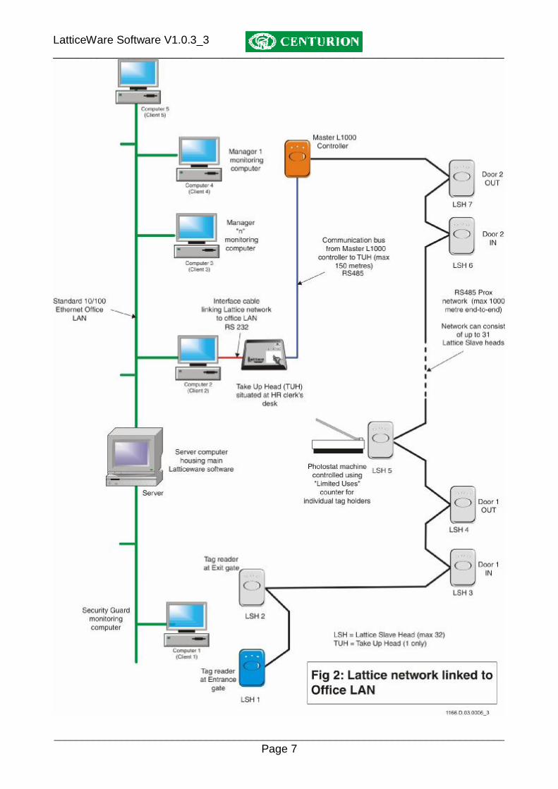
INTRODUCTION The Centurion Proximity Software suite, called LatticeWare, provides an advanced, graphical user interface (GUI) to the Centurion Lattice proximity access control system. The software is provided on a CD and is loaded onto a personal computer (PC), laptop, etc, and enables a user to administrate, maintain and monitor the tags and tag-holders (tag-holders in a company, residents in a town-house, etc) used on the access control system. (see Software Installation instructions at the end of this manual) The computer on which the software is loaded acts as a “server”, maintaining the database of all the tags and tag holders as well as other parameters. The computer is linked via a RS232 port to a take-up-head (TUH) which in turn is linked by a communication bus cable to the L1000 main controller and the rest of the “physical” access control system. The TUH can be mounted up to 150 metres away from the L1000. The take-up-head acts as a link between the proximity system and the computer network, and enables the administrator of the system to easily add, delete or modify tags using the TUH as a tag reader. Other computers on a standard LAN network may connect to the “server”), and then get access to LatticeWare. E.g. A security guard at an entrance gate can have the photograph of a tag-holder flashed up onto his screen as that user swipes his tag past the entrance reader of the complex. Each computer that needs to have access to the server computer must be connected to the server over a LAN, and have the relevant ancillary “client” program loaded. The information stored in the database is accessible via a reporting system. Fields can be filtered and sorted to extract pertinent information. There is also an export facility where information can be exported into other programs, such as MS Excel, for additional analysis. Software upgrades can be downloaded from our internet site and imported to existing systems (see, Bootload devices on page 62)
Additional Information This manual should be read in association with the following document:
• Lattice Installation manual.

LatticeWare Software V1.0.3_3 ________________________________________________________________________
________________________________________________________________________________ Page 6
LatticeWare Software V1.0.3_3 ________________________________________________________________________
________________________________________________________________________________ Page 7

LatticeWare Software V1.0.3_3 ________________________________________________________________________
________________________________________________________________________________ Page 8
INSTALLATION INSTRUCTIONS It is assumed that the L1000 controller, the Take-up-head (TUH) and the Lattice Slave Head (LSH) readers have been installed and correctly wired.
Requirements: • Centurion L1000 main access controller. • Centurion Take-up-head (TUH). • Centurion Lattice Slave Heads (if required) • RS232 serial interface cable between TUH and computer linked to RS232 port. NB: this version of LatticeWare only works on a serial port (e.g. Com1). It is therefore critical that the computer on which the software is being loaded, e.g. a Laptop, has such a port. • Twisted pair communication cable (2 pair minimum)(e.g. CAT5 screened)(RS485). • Pentium class computer with a minimum speed of 500MHz, 128 MB RAM, 500 MB hard disk and a CD Rom drive. • Server computer needs to run Windows 2000 or higher. • Optional web camera if tag-holder pictures need to be captured into the database and/or used to create tag labels. (Downloaded .JPG images from a digital camera can be used) Connections: • Ensure that the Centurion TUH is connected to an available serial port of the computer (usually COM1 or COM 2) using the serial interface cable. Normally the computer has a 9 pin DB9 connector. • Ensure that the Centurion L1000 main controller is correctly connected to the Centurion TUH by means of twisted pair communication cable. (see L1000 installation manual for wiring details – details on page 95 ). Installing LatticeWare and LatticeWare Service software: • Insert the CD into the CD Rom drive. • The installation will start automatically, or else run the setup.exe executable in the root directory of the CD. • Answer all prompts during the installation process.
Several programs are required before LatticeWare and LatticeWare Service can be installed on a computer. These are included on the disc, and will be installed automatically if required.
Microsoft.NET
Framework Microsoft Data Access Components (MDAC) 2.8
Firebird Database
LatticeWare Required Required LatticeWare Service Required Required Required

LatticeWare Software V1.0.3_3 ________________________________________________________________________
________________________________________________________________________________ Page 9
If Microsoft Data Access Components is required a dialog similar to the one below will appear:
Click OK to continue.
If you accept the terms of the license agreement, then click “I accept all the terms of the preceding license agreement.” Click Next > to continue.
LatticeWare Software V1.0.3_3 ________________________________________________________________________
________________________________________________________________________________ Page 10
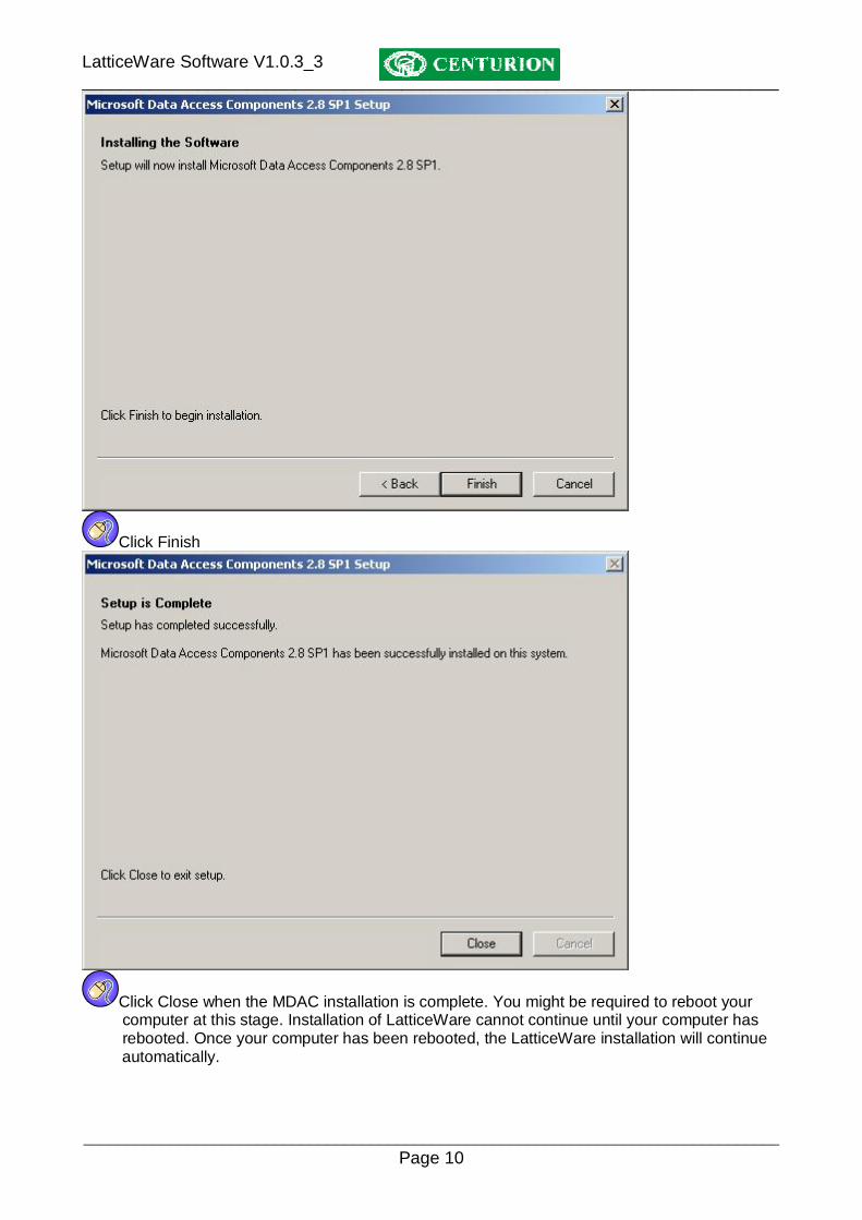
Click Finish
Click Close when the MDAC installation is complete. You might be required to reboot your computer at this stage. Installation of LatticeWare cannot continue until your computer has rebooted. Once your computer has been rebooted, the LatticeWare installation will continue automatically.

LatticeWare Software V1.0.3_3 ________________________________________________________________________
________________________________________________________________________________ Page 11
If Microsoft .NET 1.1 Framework is required the following screen will appear:
Click “Yes” to install the Microsoft .NET 1.1 Framework.
If you accept the terms of the License agreement, select “I agree” and click “Install”.
Once the Microsoft .NET Framework installation has finished click “OK”.

LatticeWare Software V1.0.3_3 ________________________________________________________________________
________________________________________________________________________________ Page 12
There may be an error installing the Microsoft .NET 1.1 Framework if the Framework already exists on the computer. In case, run the Setup.exe again, but select No in step 0.
Click Next >
Click Next >

LatticeWare Software V1.0.3_3 ________________________________________________________________________
________________________________________________________________________________ Page 13
Click Next > If both LatticeWare and LatticeWare Service are required on a computer (the typical installation when only one computer at a site is required) then click on the red cross next to LatticeWare Service and select “This feature will be installed on local hard drive”. If only the LatticeWare client is required, then ensure that there is a red cross next to LatticeWare Service, Lattice Backup and Service Manager by clicking on LatticeWare Service and selecting “This feature will not be available.” In this case, skip through to step 0.

LatticeWare Software V1.0.3_3 ________________________________________________________________________
________________________________________________________________________________ Page 14
Click Next >
Click Install

LatticeWare Software V1.0.3_3 ________________________________________________________________________
________________________________________________________________________________ Page 15
If the Firebird System is required the following dialog box will appear:
Click OK
Click Next >

LatticeWare Software V1.0.3_3 ________________________________________________________________________
________________________________________________________________________________ Page 16
Read the License Agreement, and if you accept the terms of the agreement, click “I accept the agreement” and Next >
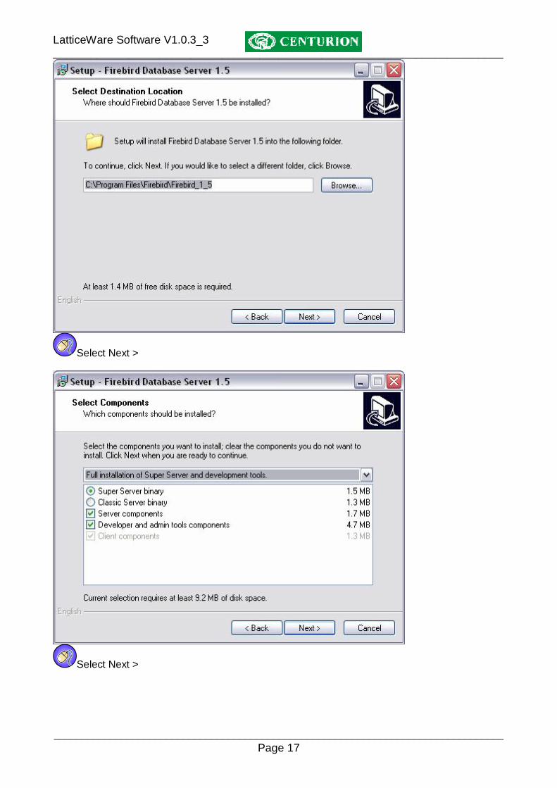
Select Next >
LatticeWare Software V1.0.3_3 ________________________________________________________________________
________________________________________________________________________________ Page 17
Select Next >
Select Next >

LatticeWare Software V1.0.3_3 ________________________________________________________________________
________________________________________________________________________________ Page 18
Select Next >
Select Next >

LatticeWare Software V1.0.3_3 ________________________________________________________________________
________________________________________________________________________________ Page 19
Select Install
Select Next >

LatticeWare Software V1.0.3_3 ________________________________________________________________________
________________________________________________________________________________ Page 20
Select Finish

LatticeWare Software V1.0.3_3 ________________________________________________________________________
________________________________________________________________________________ Page 21
LATTICEWARE SERVICE MANAGER If the LatticeWare Service Manager was installed, then the option to launch it appears. To launch the Service Manager, tick the checkbox marked “Launch LatticeWare Service Manager”. Select Finish to complete the installation.
If the LatticeWare Service Manager (Service Manager) is launched, the following icon will appear in the system tray (bottom right corner of the screen). The Service Manager is the item that looks like a traffic light and indicates if the LatticeWare Service is running or not. If the service is stopped,
the traffic light is red. The traffic light goes yellow if the service is starting or stopping, and
shows green if the service is running.
To start the LatticeWare Service, right click on the Service Manager icon, then select “Start”. When right clicking on “Show Details” LatticeWare Service Manager will open. What is LatticeWare Service?
• Windows Service – Starts automatically when PC boots up – Only runs on NT based computers (2000, XP, 2003)
• No user interface (hence LatticeWare Service Manager) • Functions:
– Passes information to client computers (running LatticeWare) – Access Control – Transaction logging – Timed Functions (Time barring, Time lock, Timed APB)
What does the Service Manager do?
• The Service Manager acts as a watchdog for LatticeWare Service • Simplifies the starting and stopping of Lattice Service • Allows Service Settings to be altered (e.g. COM Port)
Using LatticeWare Service Manager
• Consists of 6 different tabs – Settings – Notifications – Registered Clients – Maintenance – Readers – Service

LatticeWare Software V1.0.3_3 ________________________________________________________________________
________________________________________________________________________________ Page 22
– Transactions SERVICE
• Controls the service – Stop – Start
• Shows number of tags in PC and Controller databases
SETTINGS
• Serial/COM port can be changed • Remoting details can be changed • Database settings can be changed • System Settings
– Contention Resolution – Auto start the Service Manager – Controller connects to a PC – Tags with timing open if PC is disconnected

LatticeWare Software V1.0.3_3 ________________________________________________________________________
________________________________________________________________________________ Page 23
MAINTENANCE
• Can force synchronization between the Controller and PC • Allows Bootloading of the Controller and Slave Heads • Allows the Admin Password to be changed
Database Synchronization
• When the PC and a Controller connect a session ID is set up • Prevents an old PC or Controller from accidentally being connected to an existing system
overwriting the system • If the Session IDs of the PC and Controller match, then the synchronization occurs. • Controller stores tags with a Tag Index for easier searching • Controller sends tag information to PC • PC sends tag information to Controller • Controller sends reader information to PC • PC sends reader information to Controller • Database ends up as a merged combination of the two original databases
Bootloading Devices
• Bootloader allows the firmware of new products to be updated – Bug fixes – Added features
• Firmware is encrypted to protect the Intellectual Property • Bootloader program in memory of device decrypts program and rewrites program memory • Bootloader interface device required, except for LatticeWare where the TUH performs this
function

LatticeWare Software V1.0.3_3 ________________________________________________________________________
________________________________________________________________________________ Page 24
• Select Address of Device to be bootloaded
• View version information of device and code
Bootloading Process
1. Open encrypted file (*.ENC)
2. Choose address of device (only for devices with addresses that can be altered)
LatticeWare Software V1.0.3_3 ________________________________________________________________________
________________________________________________________________________________ Page 25
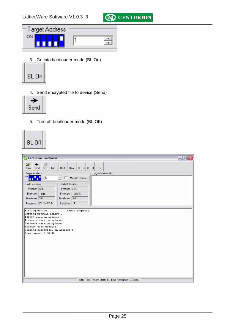
3. Go into bootloader mode (BL On)
4. Send encrypted file to device (Send)
5. Turn off bootloader mode (BL Off)

LatticeWare Software V1.0.3_3 ________________________________________________________________________
________________________________________________________________________________ Page 26
Bootloading multiple devices
• With devices on a network (e.g. LSH) each device has a unique address • Can bootload each of those devices sequentially
1. Open encrypted file (*.enc)
2. Click “Multiple Devices”
3. Choose devices to bootload
• Online devices shown in green
4. Click “Multiple Devices”
Exiting Bootloader
• Controller does not send any information to other devices while a device is in bootloader mode
• Must exit bootload process to get Controller to resume communications

LatticeWare Software V1.0.3_3 ________________________________________________________________________
________________________________________________________________________________ Page 27

LatticeWare Software V1.0.3_3 ________________________________________________________________________
________________________________________________________________________________ Page 28
NOTIFICATION
• Displays information relevant to system – Connection status – Client registration information – Errors

LatticeWare Software V1.0.3_3 ________________________________________________________________________
________________________________________________________________________________ Page 29
APPLICATION LOG
• Intended to show the rate at which commands are being passed between the Controller and the PC
• Currently disabled

LatticeWare Software V1.0.3_3 ________________________________________________________________________
________________________________________________________________________________ Page 30
REGISTERED CLIENTS
• Display the clients that have registered with LatticeWare Service
READERS
• Gives the status of the Slave Heads in the system – Online/Offline – In the database/Not in the database

LatticeWare Software V1.0.3_3 ________________________________________________________________________
________________________________________________________________________________ Page 31
LOGGING-IN AND ENVIRONMENT Logging In: It is assumed that the software is installed on the server computer
Click on the LatticeWare icon and the following “splash” screen will appear. NOTE: the software revision is shown in the top left-hand side of the screen.
Figure 1 - Lattice Splash screen
Click OK
LatticeWare Software V1.0.3_3 ________________________________________________________________________
________________________________________________________________________________ Page 32
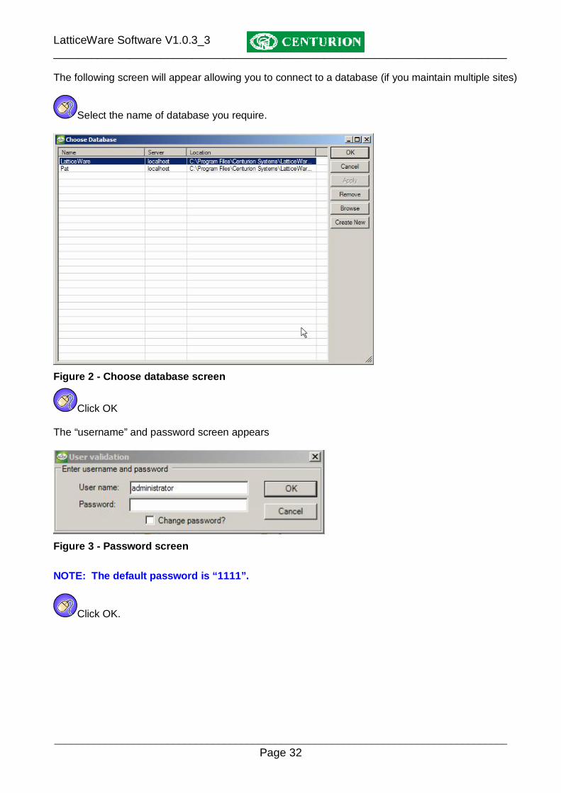
The following screen will appear allowing you to connect to a database (if you maintain multiple sites)
Select the name of database you require.
Figure 2 - Choose database screen
Click OK The “username” and password screen appears
Figure 3 - Password screen
NOTE: The default password is “1111”.
Click OK.

LatticeWare Software V1.0.3_3 ________________________________________________________________________
________________________________________________________________________________ Page 33
After logging in successfully, a window similar to the following screen will be presented, (see Figure 4). This is the central “dashboard” from which all operations are controlled. The screen comprises the standard windows interface with menu bar, information tabs, and actions icons (e.g. Add(+), Delete(-), etc).
Figure 4: Screen showing the typical “dashboard”. NOTE:
• The person who is logged in is shown at the bottom left-hand side of the screen (i.e. “administrator” in this example)
• On the bottom right-hand side of the screen there is a small icon that indicates whether LatticeWare is linked to a L1000 controller. (in this case the icon is shown as ( - Disconnected from Controller)
• The red bar at the bottom of the screen indicates proximity reader heads which are registered on LatticeWare, but are off-line. The line scrolls through all heads that are off-line. (In the screen dump shown, only head number HO1(0) is shown as off-line, but this purely because the information is frozen for the screen dump)
• The blank space between the logged-in user and the scrolling message bar is an additional message bar which will provide additional information of the operation of the system. (see Figure 93 on page 86 for an example)

LatticeWare Software V1.0.3_3 ________________________________________________________________________
________________________________________________________________________________ Page 34
TOOLBARS There are 3 different menu/tool-bars which provide the means to navigate and manipulate data. Windows menu bar This toolbar is similar to the classic MS Windows menu bar with the well-known “File, Edit, Tools…..” etc, type menus used to setup the system, select reporting functionality, etc. (see Figure 5)
Figure 5 - Windows type menu bar Information tabs: The information tabs provide access to, and editing of, the stored database information.
Figure 6 - Information tabs When the application is opened, the last used information tab is displayed. In a new system the screens would be totally un-populated. (see Figure 4). Action Icons The action icons shown in Figure 7 below enable you to start up regularly used function instead of invoking them from the Window menu bar.
Figure 7 - Action Icons
• The Add ( ) icon is used to enter totally new information not already captured into the system.
• The Delete ( ) icon will completely remove all details of the tag-holder from the database and
should be used carefully. Figure 8 shows a typical warning message that is given before allowing a deletion of a tag holder’s details.
Figure 8: Warning message before deletion of a tag holder.
• The Edit ( ) icon allows information already captured into the system to be modified. • The Refresh ( ) icon will ensure that all information on a screen is updated to the latest
available. • The Printer ( ) icon will print information to the printer.

LatticeWare Software V1.0.3_3 ________________________________________________________________________
________________________________________________________________________________ Page 35
DATA CAPTURE ORDER FOR INFORMATION TABS
It is recommended that the following steps are followed to commission the system
1. Using the “Site” tab, create a name for the site in question. (e.g. “Centurion Head Office”). Usually there would be only 1 site.
2. Using the “Units” tab, create the (business) unit(s) that exist for a site. (e.g. In a hospital there could be the following business units:- Obstetrics, Physiotherapy, ICU, Trauma unit, etc)
3. Using the “Areas” tab, create all the areas that exist within the site. (e.g. Reception area, Sales Office, Admin office, Production area, R&D wing, Computer room, etc)
4. Using the “Time periods” tab, create names for time periods during which readers would grant access to tags. (e.g. Normal Working hours might be defined as the time period 7h30 to 17h30 on weekdays only (Monday to Friday).
5. Using the “Access Groups” tab, create names for groups of people who would have identical access rights. (e.g. Sales People could be a group which includes all sales clerks in a company).
6. Using the “Access Mapping” tab, create mappings of what “Group” is allowed access into a particular “Area” during a certain “Time Period”. (E.g. one of the Access Mappings could be that the “Sales People” are allowed into the “Sales Office” anytime during “Normal Working Hours”.
7. Using the “Tag Holders” tab, enter the details for any tag holders (e.g. tag-holder in a company, or residents in a town-house complex, etc). This can be done person by person, or if a list already exists in electronic format, this list can be imported (see Importing Tag Holder details electronically setup on page 47)
8. Using the “Tag” tab, add tags to the system. There are many ways in which tags can be entered into the system. (see
9. 10. Adding tags on page 61)
LatticeWare Software V1.0.3_3 ________________________________________________________________________
________________________________________________________________________________ Page 36
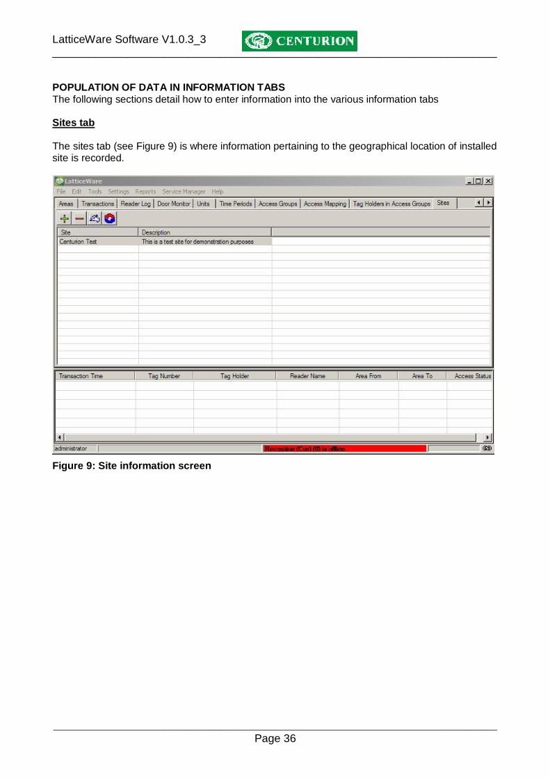
POPULATION OF DATA IN INFORMATION TABS The following sections detail how to enter information into the various information tabs Sites tab The sites tab (see Figure 9) is where information pertaining to the geographical location of installed site is recorded.
Figure 9: Site information screen

LatticeWare Software V1.0.3_3 ________________________________________________________________________
________________________________________________________________________________ Page 37
Edit/Add site A description can be added to the name of the site and this site can be colour coded. This is useful later when viewing tag-holders who take on the colour of the site to which they belong. (See Figure 10)
Figure 10: Screen showing name details of a site Add/Edit site addresses This screen (Figure 11) allows you to add/edit the address details for the tag holder.
Figure 11: Screen showing Address details for a site
TIP: If the postal address is the same as the physical address, first fill in only the physical address details and then click on the “Postal Address same as Physical?” check box to copy all the physical address details to the postal address fields.

LatticeWare Software V1.0.3_3 ________________________________________________________________________
________________________________________________________________________________ Page 38
Units Tab The “Units” information tab provides a means of grouping tag holders in groups called units (e.g. business units). This is useful when searching and listing information later (see Figure 12).
Figure 12 – Screen showing the Units information tab Add/Edit Units A description of each business unit can be created using the “add” icon and later maintained using the “edit” icon. The following screen shows the information that can be entered.

LatticeWare Software V1.0.3_3 ________________________________________________________________________
________________________________________________________________________________ Page 39
Figure 13 - Screen showing editing of a "Unit" Areas Tab An Area is the physical area where a tag-holder normally carries out work duties. A site usually has multiple areas e.g. R&D area, Sales area, Production area, etc (Figure 14).
Figure 14: Screen showing Area Information

LatticeWare Software V1.0.3_3 ________________________________________________________________________
________________________________________________________________________________ Page 40
Add/Edit Areas information The name and description of an area can be changed as shown in the screen below (Figure 15).
Figure 15 - Screen showing Edit screen for "Area" information Access Disabled?: If the Access Disabled check box is ticked, then none of the readers which lead to this area will allow anyone access to the area, until the checkbox is un-ticked. Tag-holders Present: If the system is linked to the Lattice access system, then all tag-holders who are currently within this area will be shown.

LatticeWare Software V1.0.3_3 ________________________________________________________________________
________________________________________________________________________________ Page 41
Time Periods Tab This tab shows the time periods during which a reader will grant access to a valid tag. Any number of combinations can be created to suit site requirements.
Figure 16 - Screen showing "Time periods". Add/Edit Time periods The following screen (Figure 17) shows how Time periods can be added or edited.
Figure 17 - Screen showing Add/Edit "Time Period" information

LatticeWare Software V1.0.3_3 ________________________________________________________________________
________________________________________________________________________________ Page 42
As will be seen from Figure 17, a name for the Time Period is compulsory. For each name select a “Time In”, “Time Out” and a “Day of the Week”. Use the drop down’s to select a time, or day of the week. NOTE: It is NOT possible to select a calendar day e.g. 17th Sept 2006. Access Groups Tab The Access groups tab provides a way to group specific tag holders into groups that will have similar access rights. E.g. certain tags could be created as a “Visitor” group. These tags might be granted fairly wide access rights to the building, but can then be disabled when the visitor leaves. Similarly, you could create a group called “Maintenance” which might be given to cleaning or maintenance crews that would be granted access to certain areas, or at specific times.
Figure 18 - Screen showing "Access Groups"

LatticeWare Software V1.0.3_3 ________________________________________________________________________
________________________________________________________________________________ Page 43
Add/Edit Access groups information
Figure 19 - Access Groups add/edit screen. The screen shown in Figure 19, allows creation and editing of the Access groups. The groups can be colour coded for ease of later analysis and the “Disabled” tick box provides a simple way to disable all tags which form part of this group. Access Mapping Tab The screen shown below lists the matrix of Areas, Access Groups and Time Periods that are linked to give unique tag-access. E.g. consider the highlighted line in Figure 20 below. This shows that the Visitor access group, will be allowed for the Full Day time period into the Reception area (provided of course, that the Visitor access group is NOT disabled).
Figure 20 - Screen showing Access Mappings

LatticeWare Software V1.0.3_3 ________________________________________________________________________
________________________________________________________________________________ Page 44
Add/Edit Access-Mapping details The upper section of the screen shown in Figure 21 below is broken up into 3 sections. The left-hand section shows Areas that exist in the system, the middle section shows the Access Group that is permitted access into an Area and the right-hand section lists the Time Periods during which access will be granted. The lower section of the screen shows the current mappings that already exist. To create a new mapping, highlight one (or more entries) in each the three columns on the upper section, and then click on the “Add Access Mapping” button. The new selections will be listed in the lower section. E.g. in the screen shown the following selection is being created:
Tags belonging to the Visitor access group (if not disabled) will be granted access to the Sales area for the time period called Full day.
To delete a selection(s) simply highlight them in the lower section and click on the “Remove Access Mapping” button.
Figure 21 - Access-Mappings matrix setup screen

LatticeWare Software V1.0.3_3 ________________________________________________________________________
________________________________________________________________________________ Page 45
Tag Holders Information Tab The screen dump shown in Figure 22 lists the details of Tag-holders that exist in the system. This screen shows a summary of the names and other pertinent information related to each tag holder.
Figure 22: The default tag holder screen
In Figure 22 a photograph (if created during set-up) of the tag-holder that is highlighted, (e.g. in this case Joe Bloggs), is shown to the right of the screen as well as an indication of the last reader that was tagged (e.g. the reader called the Reception reader), and the Area in which the tag holder was last in (Admin). An alphabetic (or numeric) database sort can be invoked by using the mouse to click on any of the heading field blocks (e.g. Surname, Preferred Name, etc). The sort toggles A-Z or Z-A each time the heading is clicked. The Figure 23 below shows where the Surname field has been sorted in reverse order (i.e. from Z to A)

LatticeWare Software V1.0.3_3 ________________________________________________________________________
________________________________________________________________________________ Page 46
Figure 23: Screen showing Surname sort from Z to A.
A useful additional feature is provided by the Colour Separation drop-down on the right-hand side of the screen. By clicking on the drop down it is possible to sort the tag-holders on an additional parameter by colour coding. E.g. Figure 24 below shows information highlighted by “Unit”.
NOTE: Remember to refresh data (using the refresh icon, ) if the “Colour Separation” drop-down is changed.

LatticeWare Software V1.0.3_3 ________________________________________________________________________
________________________________________________________________________________ Page 47
Figure 24: Tag-holder screen showing colour highlighting of “Cost Code” Add new Tag holder There are a number of ways that tag holder information can be inputted to the system. E.g.
• Add details by clicking on the ADD icon and filling in all details (similar to Edit Tag Holder described later)
• Import an existing database of information electronically into the system. Importing Tag Holder details electronically To import tag holder details electronically you need to have a file in CSV (Comma Separated Values) format which can be imported. This file does not have to have all fields required by LatticeWare, but obviously the more complete the data, the less work there will be later to update the tag holders’ information manually. E.g. Assume that you have a CSV file with the First names and Surnames of some tag holders that you want imported. Consider you have the following CSV file, called Tagholder1, as shown in Figure 25. (This file is very elementary but shows the principle of how information can be imported)

LatticeWare Software V1.0.3_3 ________________________________________________________________________
________________________________________________________________________________ Page 48
Figure 25 - Simple CSV file for importing Tag Holder information Go to the toolbar and select “Import Employee data” as shown in the screen (Figure 26) below.
Figure 26 - "Import Employee data" menu A screen similar to that shown in Figure 27 will be shown. Search your computer for the location of the CSV (e.g. in this example the file called Tagholder1 is shown in the folder called “Centurion Prox”). Make sure that the CSV file you require is listed in the “File name” block and then click on “Open”
Figure 27 - Location of CSV import file

LatticeWare Software V1.0.3_3 ________________________________________________________________________
________________________________________________________________________________ Page 49
An import matching data screen similar to that shown in Figure 28 will appear. In the left-hand side (LHS) of the screen the filed names at the top of the Tagholder1 file are shown. On the right-hand side (RHS) of the screen is the list of field names and their “type” that exists in the LatticeWare database.
Figure 28 - Import data matching screen You now have to match the left-hand and right-hand sets of information. This is done by clicking and dragging each of the fields on the LHS to its matching field on the RHS. NOTE: As the fields from the LHS are dropped onto the RHS, the LHS data fields are highlighted to show that the matching is complete and the “Field name” from the LHS is shown in the “Mapping” column of the RHS.
Click on “Finish” to import the information.

LatticeWare Software V1.0.3_3 ________________________________________________________________________
________________________________________________________________________________ Page 50
Figure 29 - Matched fields on the Import data screen If the import of the data is successful a message similar to that shown in Figure 30 is given
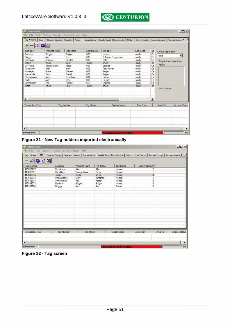
Figure 30 -" Data import successful" message The result of the data import example just given is shown in Figure 31. For the sake of clarity the two new tag holders are shown highlighted. NOTE: Because our import file had only First Name and Surname imported, all other details for these two tag holders is blank (i.e. shown as “<null>”.
LatticeWare Software V1.0.3_3 ________________________________________________________________________
________________________________________________________________________________ Page 51
Figure 31 - New Tag holders imported electronically
Figure 32 - Tag screen

LatticeWare Software V1.0.3_3 ________________________________________________________________________
________________________________________________________________________________ Page 52
Edit Tag Holder
Click the Add button to enter information for a new tag-holder, or the Edit button if information for an existing tag-holder needs to be modified. The Edit screen can also be activated by double clicking on the required tag-holder. An example of the Edit details screen is shown in Figure 33. As will be seen, tag-holder details are divided up into several “information tabs”. Each of these tabs will be discussed separately.
Figure 33: Typical example of “Tag-holder –Personal Details” edit screen
All fields marked with a red asterisk (*) are compulsory fields and must be filled in. If the information is not correctly filled-in the fields with errors are shown in red and it is not possible to exit. (Figure 34):

LatticeWare Software V1.0.3_3 ________________________________________________________________________
________________________________________________________________________________ Page 53
Figure 34: Failed validation screen. The sets of arrows on the right hand, and lower, section of the screen are a convenient means of scrolling through tag-holder data. The vertical arrows will cycle through each of the tag-holders in the database for a specific screen, while the horizontal arrows move from information-tab to information-tab (e.g. Name, Car, Addresses, etc) for the selected tag-holder. Apart from self- explanatory tag-holder details, the following fields are provided: Status field in the Tag Holder - Personal Details tab: The drop down allows the following tag status to be selected: Active – The tag used by this tag-holder is fully active on the access control system. Suspended – The tag-holder remains on the database but will not be able to gain access to the premises via the access control readers until after the Expiry Date is reached. E.g. a tag-holder could be suspended from work as a result of a disciplinary hearing. (Note: the Expiry Date is blanked out for active and inactive tag-holders) Inactive – Any tag linked to this tag-holder will be totally inactive. (e.g. the tag-holder may be on leave). Guest – The tag-holder is a treated as a “guest” and would have limited access rights, etc. An expiry date can be set at which time the linked tag for this tag-holder would cease to function. Tag-holder’s Last Area: This block cannot be populated manually. This information will appear when the software is linked to a fully working access control system, and will indicate the last zone in which this tag-holder was recorded. This can be very useful to a receptionist who could monitor the whereabouts of a tag-holder in a large building complex. Tag-holders Last Reader: Similar to the previous field, this block cannot be populated automatically. In a working system it indicates the last reader tagged by this tag-holder.

LatticeWare Software V1.0.3_3 ________________________________________________________________________
________________________________________________________________________________ Page 54
Print Label button: This button will print tag-holder details to a printer enabling a label to be made which can be inserted into the tag. Tag-holder – Car Details Tab. This screen allows you to update information related to the tag holder’s motor car details
Figure 35: Screen showing (Motor) Car details

LatticeWare Software V1.0.3_3 ________________________________________________________________________
________________________________________________________________________________ Page 55
Tag-holder – Addresses
Figure 36: Screen showing Address details
Once the residential address has been completed, you can check the “Postal Address same as Residential?” check box to automatically complete the postal address information. Tag-holder – Work Specific Work related information specific to the tag-holder is entered on the screen shown in Figure 37. Apart from obvious fields the following possibly require additional explanation. Unit: Tag-holders can be allocated to specific work units e.g. an electrical, mechanical, repairs, or sales, unit, etc. This can be useful during sorting and reporting. Cost Code: A tag-holder can be assigned a specific cost code for sorting or accounting purposes. Picture: If a digital image (photograph) of the tag-holder has been captured this will be visible in the block.
Figure 37: Screen showing work specific information

LatticeWare Software V1.0.3_3 ________________________________________________________________________
________________________________________________________________________________ Page 56
If a web camera is available a picture of the tag-holder can be captured by clicking on Take Picture
( ) icon. The Available Devices will list any cameras linked to the computer (see Figure 38). Once a camera has been selected from the drop down the Start preview, Capture Images, and Stop Preview buttons will be available for use. The screen above shows these buttons “greyed out” because no camera is connected.
Figure 38 - Photograph capture via web-cam
Click on the Start Preview button to capture a photograph. The camera will take “snap-shots” of the tag-holder at time intervals determined by the Frame delay information box. The default interval time is shown as 150 milliseconds but can be changed. A sample of 16 images will appear on the screen.

LatticeWare Software V1.0.3_3 ________________________________________________________________________
________________________________________________________________________________ Page 57
Figure 39: Capture photo screen Once a set of suitable images has been captured, click on the Stop Preview button. Select the best of the images by clicking on the image required, and then click on the Capture Images to save this image to the database.
An alternative method of capturing a photograph is to use the Browse button ( ) in Figure 37 to find an image stored elsewhere, and save that image to the LatticeWare database. To do this, proceed as follows:
• Click on Browse. • Search through the folder structure to find the require JPEG image.
• Click on the required file and then click on Open. • The image will appear in the Picture block.

LatticeWare Software V1.0.3_3 ________________________________________________________________________
________________________________________________________________________________ Page 58
Tag numbers: If any tag (or tags) are linked to this tag-holder they will be shown in the window. If a
tag needs to be captured, then the Grab Tag button ( )is clicked and the required tag(s) is (are) presented to a reader. It is possible to select the reader that will be used. In most cases the Take-up-head (TUH) would be used. To ensure that the correct tag has been presented the tag has to be presented twice (similar to confirmation of a password). After checking that the correct tag has been captured, click on the End Grab button. Any incorrect tags can be deleted by clicking on the Delete button. Access groups Selection This screen also allows for the tag holder to be allocated to one (or multiple) Access Groups. Click on the check boxes to select to which Access Group the tag-holder should belong. Tag-holder – Telephone and email The following screen (Figure 40) shows the screen where telephone and email information can be captured.
Figure 40: Screen showing telephone and email entry fields

LatticeWare Software V1.0.3_3 ________________________________________________________________________
________________________________________________________________________________ Page 59
Tag-holder – General Additional information pertaining to the tag-holder can be entered on the General screen as shown in figure 43.
Figure 41: Screen showing additional general information entry fields
It will be noticed that extra Text, Lookup and Date fields can be added. By double clicking the label it is possible to modify the label description. In the example shown Extra Text field 1 and Extra Text field 2 and Extra Date 1 have been replaced with Hair Colour and Spouses name and Birthday respectively. Tag-Holder – User rights tab Each tag-holder has certain rights in the system. E.g. in the example shown in Figure 42, the tag holder, Bridget Bardotte is permitted to Edit “Units” and “Time Periods” information. This is critical where many tag-holders may have access to the system on their own computers linked to the main server.

LatticeWare Software V1.0.3_3 ________________________________________________________________________
________________________________________________________________________________ Page 60
Figure 42 - The Tag Holder's User rights tab Tag Tab This tab lists all the tags currently stored in the database and to whom the tag has been allocated. E.g. In Figure 43, is a list of tags that have been learned into the system and tag-holder details of the tag in cases where a tag has been allocated. Notice that tag number 117635975 (highlighted) is NOT allocated to a tag holder.
Figure 43 - Screen showing the Tags Tab information

LatticeWare Software V1.0.3_3 ________________________________________________________________________
________________________________________________________________________________ Page 61
Adding tags There are many ways that tags can be added to the system. E.g.
• Add tags directly from a reader using the functionality associated with the “Admin” tag. (For details see the Lattice installation manual on page 5).
• Enter tags using one of the main toolbar’ “Tools” menu items. • Enter tags from the Tag Holder – Work Specific tab.
Quick Add New Tags Let us assume there are no tags yet entered into the system, and that 100 need to be imported into the system. The easiest way to enter multiple tags is to go to the main toolbar “Tools” menu as shown in Figure 44:
Figure 44 - "Quick Add New Tags" menu The following screen (Figure 45) is produced when the “Quick Add new Tags” menu is selected:
Figure 45 - Capture screen for Multiple new tags Select the reader on which the tags are to be read. As the tags are presented to the reader, the encrypted tag number will be shown.

LatticeWare Software V1.0.3_3 ________________________________________________________________________
________________________________________________________________________________ Page 62
See Figure 46 which shows where 3 tags have been captured.
Figure 46 - Quick capture of tags Quick Add New Tags to Tag Holders Adding tags to certain specific tag holders can be done using the following menu (Figure 47) from the “Tools” toolbar.
Figure 47 - "Quick Add New Tags to Tag Holders" menu

LatticeWare Software V1.0.3_3 ________________________________________________________________________
________________________________________________________________________________ Page 63
The screen (see Figure 48) is produced when the “Quick Add new Tags to tag Holders” menu is selected.
Figure 48 - "Quick Add Tags to Tag Holders" screen As can be seen the screen is divided into two columns. The left hand side (LHS) of the screen shows a list of tag-holders while the right hand side RHS) of the screen is unpopulated. The idea behind this menu is to allocate tags to tag-holders. Firstly the tag-holders should be sorted into some order. E.g. alphabetically or by tag-holder number. Click on the required heading to perform a sort. In the example shown the names are sorted by Surname. The tag-holders are then transferred from the LHS to the RHS of the screen (or back) by using the arrows in the centre of the screen. The order in which the tag-holders should be listed must then tie up with the order in which tags will be captured using a tag reader. NOTE: The identity number of a tag can be held constant, or can be made to increment from some number as shown below (Figure 49).
Figure 49 - Close up of Identity number settings The reader to be used is shown in the Take On Reader drop-down menu. E.g. “Take Up Head” in this example).

LatticeWare Software V1.0.3_3 ________________________________________________________________________
________________________________________________________________________________ Page 64
Tag-holders are selected by clicking on a tag-holder and using (ctrl + click) to select individual additional tag-holders, or (shift + click) to select a contiguous group of tag-holders. Then use the arrows in the centre of the screen to move single or groups of tag-holders from one side of the screen to the other as follows: >> - moves all tag-holders on LHS to RHS
> - moves only the highlighted tag-holders on LHS to RHS
< - moves only the highlighted tag-holders on RHS to LHS
<< - moves all tag-holders on RHS to LHS As an example, let us assume that the two new tag holders (Brown and White) do not have tags allocated to them. Once the tag holders (Brown and White) have been selected, click on the “>” icon to move these tag holders to the RHS of the screen (see Figure 50) which shows Brown and White on the RHS of the screen. NOTE: As tags are presented to the reader they will be allocated to the tag holders in the order shown in the “Add Order” column and their identity numbers will be a shown. (by highlighting a line it is possible to change the identity number of the tag that will be allocated. See Identity Number column on the RHS for Brown in Figure 50)
Figure 50 - Selecting of Tag holders for tag update Once all the tag holders have been moved to the RHS of the screen, click on “Capture Tags” button and present the tags in the required order. Quick Add Existing Tags to Tag Holders If there are existing tags which have been learned into the system, but have not been allocated to a specific tag holder, proceed as follows:

LatticeWare Software V1.0.3_3 ________________________________________________________________________
________________________________________________________________________________ Page 65
Use the menu from the “Tools” toolbar as shown in figure 53:
Figure 51 - Quick Add Existing Tags to Tag Holders" menu The following screen (see Figure 52) is produced when the “Quick Add Existing Tags to tag Holders” menu is selected.
Figure 52 - "Quick Add Existing Tags to Tag Holders" screen As can be seen the screen is divided into two columns. The left-hand side (LHS) shows the current tag holders in the system, while the right-hand side (RHS) shows the tags in the system and to whom they are allocated. As will be seen from this example only tag number 117635975 is unallocated to a tag holder. Select a tag holder from the LHS and drag it (press and hold the left mouse button while moving) to the unallocated tag on the RHS. As the mouse button is released the name of the new tag holder will be shown. NOTE: If you try to drop the selected tag holder onto a tag that has an existing name allocated to it you will get the following warning message:

LatticeWare Software V1.0.3_3 ________________________________________________________________________
________________________________________________________________________________ Page 66
Figure 53 - Warning message if trying to overwrite tag holder details. Edit tag attributes
The attributes of each tag can be viewed and then edited by clicking on the Edit icon ( )of the Tag Tab. This brings up the screen shown in the screen shown in Figure 54
Figure 54 - Tag attributes screen NOTE: This tag holder, Joe Bloggs, with tag 118339766, has anti-passback set on the Reception (Con) and Admin (H01) readers. This screen also gives information of the tag holder’s Tag User Level (e.g. Admin rights), the Identity number allocated to the tag (0 - this tag was probably the first learned into the system and therefore became the “Admin” tag) as well as his current APB level (0).

LatticeWare Software V1.0.3_3 ________________________________________________________________________
________________________________________________________________________________ Page 67
Limited Uses Counter 0 to 3 : These 4 counters store a value between 1 and 65535. It is possible to modify the field heading description by simply double clicking on the description and modifying it. Thus, in the example shown “Limited Uses Counter 1” has been changed to “Coffee Vending Machine”. A reader linked to the Coffee Vending machine would allow Joe Bloggs to operate the coffee machine 5 more times before the counter value reduces to zero. (see full functionality description in the L1000 manual.) Expand Tree View?: The information in the window lists the readers connected to the system. By clicking on the tick box, the display will expand (or contract) and give detailed information on the functionality of the tag at the reader. See screen marked which shows the contracted view :
Figure 55 - Tag attributes screen with contracted view

LatticeWare Software V1.0.3_3 ________________________________________________________________________
________________________________________________________________________________ Page 68
Toolbar functionality The functionality of the various toolbar menus will be described in more detail. Toolbar - File As can be seen from the highlighted File toolbar in the screen below “Log off user” and “Exit” can be selected.
Figure 56 - "File" toolbar menu “Log off user” will allow a different user to log-in. The previous user is automatically logged off. The “Exit” option will close down the LatticeWare programme. NOTE: The icon in the top right-hand side of the main screen will also shut down LatticeWare. Toolbar - Edit In the following screen the Edit toolbar was clicked.
Figure 57 - "Edit" toolbar menu This toolbar duplicates the Add/Edit/Delete/Refresh functionality that is shown on each tab, and is therefore not discussed further here. Toolbar - Tools The following screens shows functionality under the Tools menu. Toolbar – Tools – Quick Add New Tags This menu allows you to quickly add multiple tags to the system. See Quick Add New Tags on page 61 for full details of the functionality provided by the menu shown in Figure 58.

LatticeWare Software V1.0.3_3 ________________________________________________________________________
________________________________________________________________________________ Page 69
Figure 58 - "Quick add New Tags" menu Toolbar – Tools –Add New Tags to Tag Holders This menu, shown in (Figure 59) below, is typically used to add new tags to tag holders that already exist in the database (e.g. after importing tag holder information electronically). See Quick Add New Tags to Tag Holders on page 62 which describes in detail how this is done.
Figure 59 - "Quick Add New Tags to Tag Holders" menu Toolbar – Tools –Add Existing Tags This menu, shown in (Figure 60) below, is typically used to add existing, unallocated, tags to tag holders. (e.g. a tag exists previously used by an employee who resigned, and this tag now needs to be allocated to a new employee taking her place). See Quick Add Existing Tags to Tag Holder on page 64 which describes in detail how this is done.
Figure 60 - "Quick Add Existing Tags to tag Holders" menu

LatticeWare Software V1.0.3_3 ________________________________________________________________________
________________________________________________________________________________ Page 70
Toolbar – Tools – Import into database This menu shown in Figure 61 below allows you to import tag holder data electronically from a CSV (Comma Separated Value) file.
Figure 61 – “Import Tag Holder data electronically” menu Full details of data import in shown in the section Importing Tag Holder details electronically described on page 47. Toolbar – Tools – Reconnect to host This menu is used by a LatticeWare user on the LAN who has lost connection with the LatticeWare server for some reason.
Figure 62 - "Reconnect to Host" menu Toolbar – Tools – Export Data The export data menus allow you to export information, stored in the various tables of the LatticeWare database, into a file that can be manipulated by an external programme. (E.g. MS Excel). NOTE: It is important to realise that this form of export gets information directly from the database tables and will often have information in a form that might not be useful to you. There is an alternative form of exporting data which gives more of a WYSIWYG (what you see is what you get) output (see figure 69)

LatticeWare Software V1.0.3_3 ________________________________________________________________________
________________________________________________________________________________ Page 71
Let us assume that we wish to export the Access Groups Table shown in Figure 63 below.
Figure 63 - "Export Data" menu
Clicking on the “Access Groups Table” will produce a screen similar to that shown in Figure 64.
Figure 64 - Save Export file
LatticeWare Software V1.0.3_3 ________________________________________________________________________
________________________________________________________________________________ Page 72
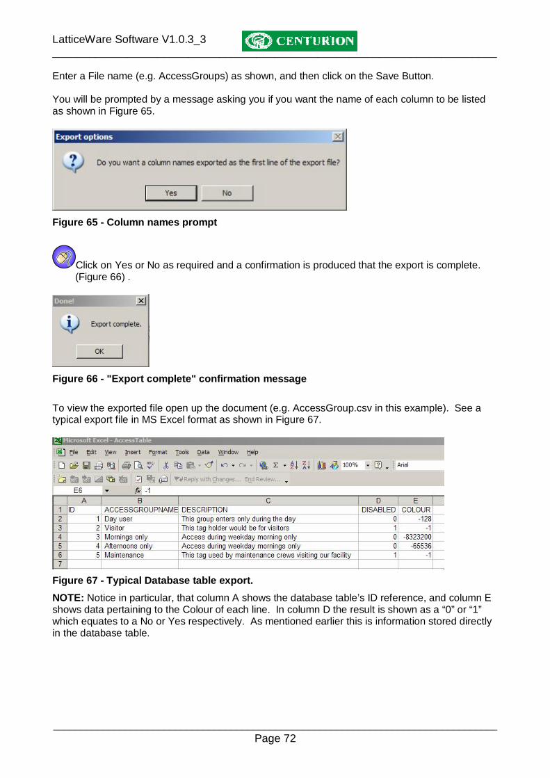
Enter a File name (e.g. AccessGroups) as shown, and then click on the Save Button. You will be prompted by a message asking you if you want the name of each column to be listed as shown in Figure 65.
Figure 65 - Column names prompt
Click on Yes or No as required and a confirmation is produced that the export is complete. (Figure 66) .
Figure 66 - "Export complete" confirmation message To view the exported file open up the document (e.g. AccessGroup.csv in this example). See a typical export file in MS Excel format as shown in Figure 67.
Figure 67 - Typical Database table export. NOTE: Notice in particular, that column A shows the database table’s ID reference, and column E shows data pertaining to the Colour of each line. In column D the result is shown as a “0” or “1” which equates to a No or Yes respectively. As mentioned earlier this is information stored directly in the database table.

LatticeWare Software V1.0.3_3 ________________________________________________________________________
________________________________________________________________________________ Page 73
Alternative Export process The following is an alternative way in which to export data and may be preferable as it gives the exact information that appears on the screen. For example:
• Choose a screen you wish to export and right click. • On the menu that is brought up click on “Export”
E.g. Access Groups is being exported in the example in Figure 68
Figure 68 - Export "Access Groups" Identical prompts to those described in the “Tools – Export data” menu will be given. The result of the information exported is shown in Figure 69
Figure 69 - Export of “Access Group” Screen data only As will be seen the information shown in Figure 69 ties up exactly with the screen information from which it was exported (see Figure 68)

LatticeWare Software V1.0.3_3 ________________________________________________________________________
________________________________________________________________________________ Page 74
Toolbar – Settings – Edit Cost Code Colours The menus shown in Figure 70 and Figure 71 enable you to allocate a colour to a Cost Code and a Tag Status. Colour-coding Cost codes or tag status makes it easier to view this data in reports. See example after Figure 71 below.
Figure 70 - "Edit Cost Code Colours" menu Toolbar – Settings – Edit Tag Status Colours
Figure 71 - "Edit Status Colours" menu
EXAMPLE: By clicking on “Edit Status Colours” a screen similar to that shown in Figure 72 below is produced.
Figure 72 - Edit Tag Status colours table
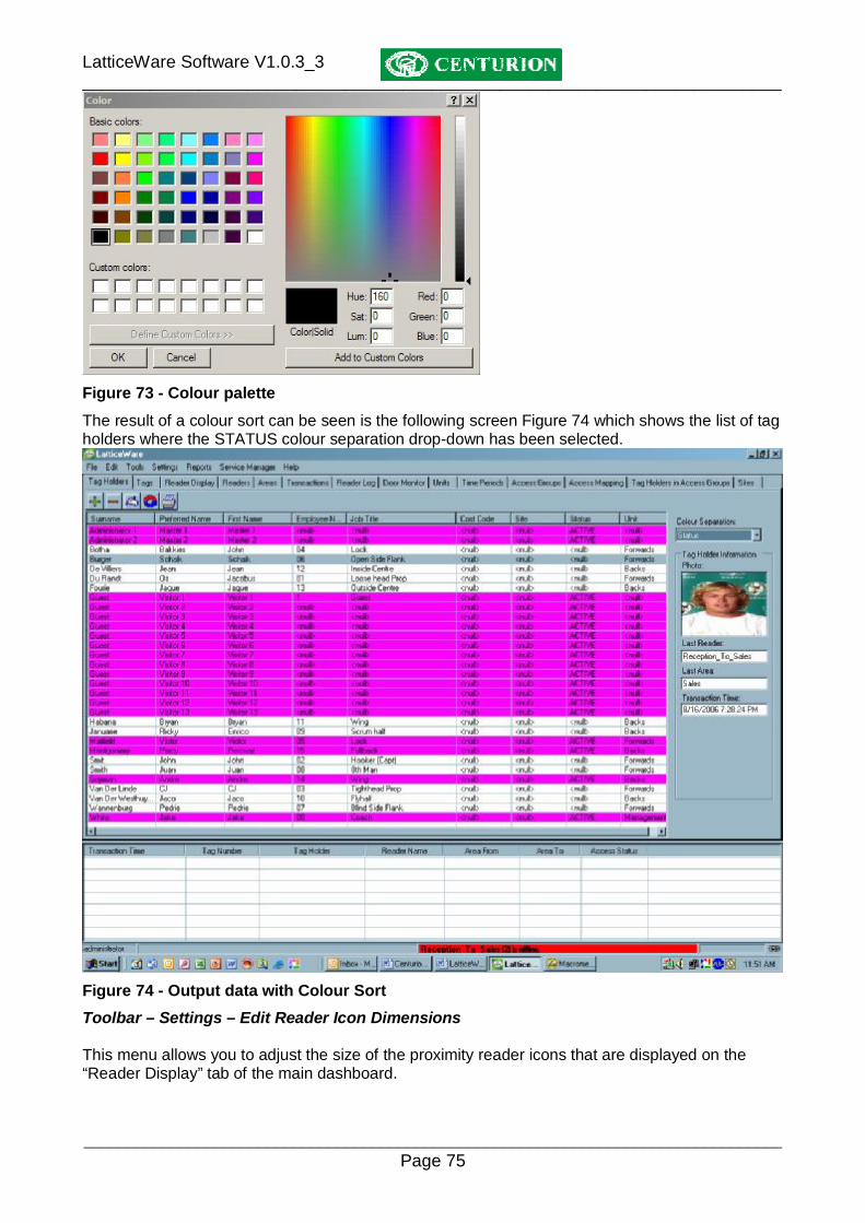
If you double click on any line the colour palette shown in is brought up and allows you to select any colour.
LatticeWare Software V1.0.3_3 ________________________________________________________________________
________________________________________________________________________________ Page 75
Figure 73 - Colour palette The result of a colour sort can be seen is the following screen Figure 74 which shows the list of tag holders where the STATUS colour separation drop-down has been selected.
Figure 74 - Output data with Colour Sort Toolbar – Settings – Edit Reader Icon Dimensions This menu allows you to adjust the size of the proximity reader icons that are displayed on the “Reader Display” tab of the main dashboard.

LatticeWare Software V1.0.3_3 ________________________________________________________________________
________________________________________________________________________________ Page 76
Figure 75 - "Edit Reader Icon Dimensions" menu The icon dimensions can be changed in Figure 76 below by using the scroll tabs on the RHS or by typing in new dimensions directly.
Figure 76 - Edit Reader Icon Dimensions Toolbar – Settings – Edit Database location
Figure 77 - "Edit Database Location" menu

LatticeWare Software V1.0.3_3 ________________________________________________________________________
________________________________________________________________________________ Page 77
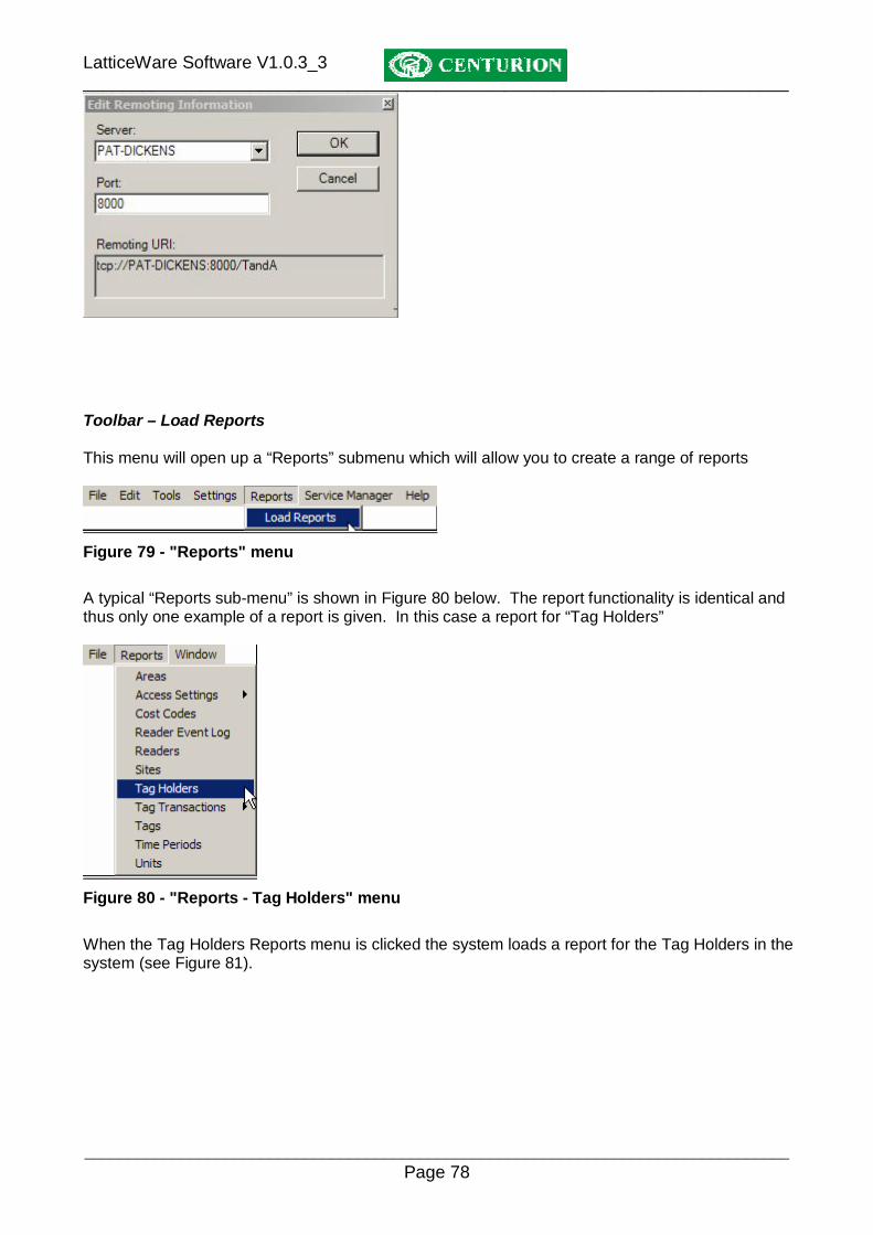
Toolbar – Settings – Edit Remoting information
Figure 78 - "Edit Remoting Information" menu
LatticeWare Software V1.0.3_3 ________________________________________________________________________
________________________________________________________________________________ Page 78
Toolbar – Load Reports This menu will open up a “Reports” submenu which will allow you to create a range of reports
Figure 79 - "Reports" menu A typical “Reports sub-menu” is shown in Figure 80 below. The report functionality is identical and thus only one example of a report is given. In this case a report for “Tag Holders”
Figure 80 - "Reports - Tag Holders" menu When the Tag Holders Reports menu is clicked the system loads a report for the Tag Holders in the system (see Figure 81).

LatticeWare Software V1.0.3_3 ________________________________________________________________________
________________________________________________________________________________ Page 79
Figure 81 - Tag Holders report screen From this screen it will be seen that there is the functionality to be able to FILTER and ORDER the information in the screen. For example assume we want to list only tag holders who belong to the UNIT called “Cricket” and have a status of “ACTIVE”. At the same time you want to sort in ascending alphabetic on Surname. We would thus have to create two filters. One filter would be set up for filtering on UNIT and the other on STATUS.
NOTE: • Additional filters are created by clicking on the ( ) icon. • Click on APPLY get the report to apply any filters or sorts. • Click on CLEAR to go back to the original information that is loaded from the database. • Click on to print the report to a printer.
• Click on one of to list multiple pages at a time.
• Click on the zoom button allowing the main screen information to be enlarged or reduced for better visibility.

LatticeWare Software V1.0.3_3 ________________________________________________________________________
________________________________________________________________________________ Page 80
Figure 82 - Tag holders sorted and filtered. Toolbar – Service Manager - Bootload Devices This menu allows you to revise the firmware on the readers if or when revisions occur. Centurion will make available to its customers the latest version of firmware free of charge. This firmware which is in encrypted form, will be available for download from the Centurion web-site www.centsys.co.za or could be emailed directly if required. NOTE: You have to be linked to the L1000 controller and any of the Lattice Slave heads (LSH’s) to be able to perform this function.
Figure 83 - Bootload devices menu
Clicking on the “Bootload Devices” menu opens up the screen shown in Figure 84

LatticeWare Software V1.0.3_3 ________________________________________________________________________
________________________________________________________________________________ Page 81
Figure 84 - Bootloader main screen
Click on OPEN. This will open up a browse window to enable you to search for the version of firmware which you wish to download. The browse window shown below (Figure 85) shows a range of firmware versions for the LSH. In this case, version LSH 1_0_10 has been selected.

LatticeWare Software V1.0.3_3 ________________________________________________________________________
________________________________________________________________________________ Page 82
Figure 85 - Firmware browse window
Click on OPEN. The condensed screen in Figure 88 shows that the code to be loaded is as follows:
• Product (AEU) – this is a unique alphanumeric allocated by Centurion to each of its products
• Firmware version 1.0.10 • Hardware version 3.0. This is related to a particular printed circuit board revision which
may have special requirements as far as code version that can be downloaded. • Microprocessor family e.g. PIC16F876A
The system has also identified that it will start at LSH reader 1 (Target reader)

LatticeWare Software V1.0.3_3 ________________________________________________________________________
________________________________________________________________________________ Page 83
Figure 86 - Firmware code loaded
Click on the button marked “BL On” (Bootloader On) and the screen is updated to show the actual software loaded into the Product in question. The firmware version is 1.0.008 and the serial number is 26.
Figure 87 - Product firmware code actually loaded
LatticeWare Software V1.0.3_3 ________________________________________________________________________
________________________________________________________________________________ Page 84
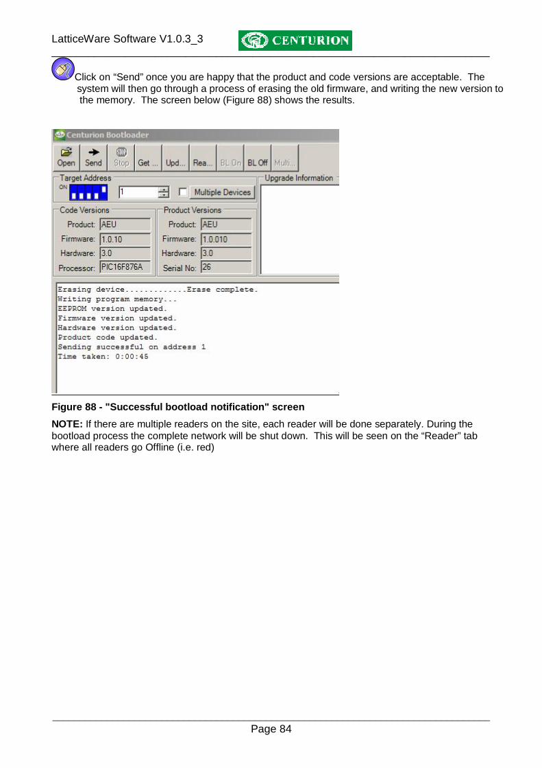
Click on “Send” once you are happy that the product and code versions are acceptable. The system will then go through a process of erasing the old firmware, and writing the new version to the memory. The screen below (Figure 88) shows the results.
Figure 88 - "Successful bootload notification" screen NOTE: If there are multiple readers on the site, each reader will be done separately. During the bootload process the complete network will be shut down. This will be seen on the “Reader” tab where all readers go Offline (i.e. red)

LatticeWare Software V1.0.3_3 ________________________________________________________________________
________________________________________________________________________________ Page 85
REMEMBER to click “BL Off” and to exit the screen when complete to allow the system to reconnect. NOTE: It is possible to bootload only certain readers in a multiple reader site by using the “Multiple Devices” button. The following screen (Figure 89) shows the devices (readers) on the system. The readers highlighted in green are those on the system. Thus, in this example, only device 1 is available.
Click on those readers which you want to update.
Figure 89 - Bootload Multiple Devices NOTE: The icon ( ) will automatically select all devices. The icon ( ) will automatically de-select all devices.
Toolbar – Service Manager Edit COM port This menu allows you to select the serial port to be used for commection to the Take UP Head (TUH).
Figure 90 - "Edit COM Port" menu
Click on the “Edit COM Port” menu and the following screen will be shown. (Figure 91).
LatticeWare Software V1.0.3_3 ________________________________________________________________________
________________________________________________________________________________ Page 86
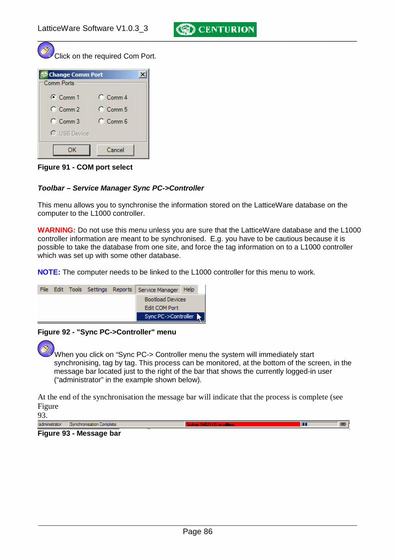
Click on the required Com Port.
Figure 91 - COM port select Toolbar – Service Manager Sync PC->Controller This menu allows you to synchronise the information stored on the LatticeWare database on the computer to the L1000 controller. WARNING: Do not use this menu unless you are sure that the LatticeWare database and the L1000 controller information are meant to be synchronised. E.g. you have to be cautious because it is possible to take the database from one site, and force the tag information on to a L1000 controller which was set up with some other database. NOTE: The computer needs to be linked to the L1000 controller for this menu to work.
Figure 92 - "Sync PC->Controller" menu
When you click on “Sync PC-> Controller menu the system will immediately start synchronising, tag by tag. This process can be monitored, at the bottom of the screen, in the message bar located just to the right of the bar that shows the currently logged-in user (“administrator” in the example shown below). At the end of the synchronisation the message bar will indicate that the process is complete (see Figure 93.
Figure 93 - Message bar

LatticeWare Software V1.0.3_3 ________________________________________________________________________
________________________________________________________________________________ Page 87
Toolbar – Help menu This menu is useful if you wish to find out what version of LatticeWare software is loaded.
Figure 94 - "About" menu
Clicking on the “About” menu lists the LatticeWare software version as shown in Figure 95 below.
Figure 95 - LatticeWare Version screen Readers tab This tab shows details of readers existing in the network. See Figure 96 below.
Figure 96: Screen showing details of readers connected to the network
Reader Display
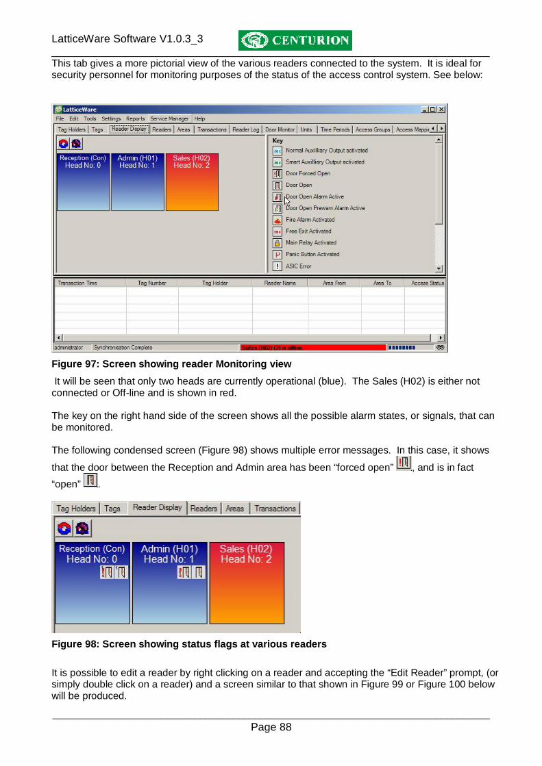
LatticeWare Software V1.0.3_3 ________________________________________________________________________
________________________________________________________________________________ Page 88
This tab gives a more pictorial view of the various readers connected to the system. It is ideal for security personnel for monitoring purposes of the status of the access control system. See below:
Figure 97: Screen showing reader Monitoring view It will be seen that only two heads are currently operational (blue). The Sales (H02) is either not connected or Off-line and is shown in red. The key on the right hand side of the screen shows all the possible alarm states, or signals, that can be monitored. The following condensed screen (Figure 98) shows multiple error messages. In this case, it shows
that the door between the Reception and Admin area has been “forced open” , and is in fact “open” .
Figure 98: Screen showing status flags at various readers
It is possible to edit a reader by right clicking on a reader and accepting the “Edit Reader” prompt, (or simply double click on a reader) and a screen similar to that shown in Figure 99 or Figure 100 below will be produced.

LatticeWare Software V1.0.3_3 ________________________________________________________________________
________________________________________________________________________________ Page 89
The information in Figure 99 pertains to the L1000 controller only, while Figure 100 shows information on the Lattice slave heads (LSH). As will be seen the information is virtually identical. Specific mention of LSH features will only be made where specific differences occur.
Figure 99: Screen showing Editing of the L1000 controller only

LatticeWare Software V1.0.3_3 ________________________________________________________________________
________________________________________________________________________________ Page 90
Figure 100 – Screen showing Editing of LSH details Add/Edit Reader information The following explains the setup of the various fields shown in Figure 99. Name: This is a compulsory field to identify the reader. It can be given a name such as Reception (in this example, the information in parenthesis “Con” indicates that this reader is the L1000 controller). “Con” might be easier to show on a sketch of a site. Description: This is a more detailed description of the reader. E.g. Door from Reception to Admin Office. Head Number: This is a compulsory field and is the number of this reader (The Master L1000 reader (head) is defined as 0 and the Lattice Slave Heads (LSH’s) must fall between 1 and 31). The binary code of this reader is shown beneath this field (only in the case of the LSH’s) and is created automatically based on the decimal value of the reader. This binary value ties up directly with the DIP switch settings on the LSH’s of the access control system. (See instruction manual for L1000 system for more details). E.g. a LSH with decimal number 9 would be binary number 01001 and the DIP switch would be set OFF-ON-OFF-OFF-ON. FRX/FIRE/PANIC: Because of the limited number of terminals for wiring a decision has to be made if the FRX-FIRE terminal is going to be used as a free exit input, a fire contact, or a panic contact.
LatticeWare Software V1.0.3_3 ________________________________________________________________________
________________________________________________________________________________ Page 91
Buzzer on Tag Activation checkbox: If checked the buzzer on the reader will sound every time a tag is presented to the reader. SMART Switch on CHD line: If the box is ticked the system expects to have a Centurion SMART Switch 2 connected. The SMART Switch improves the security of the system. (Contact Centurion for further details on the SMART Switch) SMART Switch on Alarm Line: If a Centurion SMART Switch 2 is available it is possible to link it to the Alarm line for improved security. On Fire Alarm Open Door: Tick this block if the door must open if the system has been configured for Fire Alarm and the fire contact is closed. On Fire Sound the Local Alarm: Tick this block if the reader buzzer must sound if the system has been configured for Fire Alarm and the fire contact is closed. On Fire Sound External Alarm: Tick this block if an externally connected Alarm or siren must sound if the system has been configured for Fire Alarm and the fire contact is closed. On Panic Sound the Local Alarm: Tick this block if the reader buzzer must sound if the system has been configured for Panic and the Panic contact is closed. On Panic Sound External Alarm: Tick this block if an externally connected Alarm or siren must sound if the system has been configured for Panic and the Panic contact is closed. Only Admin Tag Clears Door Forced Indication: Tick this block if you want the door forced alarm to be reset using ONLY an Admin tag. If un-ticked any tag will reset the alarm. Lock Door on Open: Tick this block if you want to apply a continuous “open” pulse to the relay contact. WARNING: care must be exercised with the type of lock used. Some solenoid locks will not tolerate a continuous DC pulse applied to them and will burn out. Magnetic locks, however, are ideally suited where this type of functionality is required. Enable Door Sense: Tick this box if you wish to fit a door contact which gives a signal to the reader that the door is open. The contact must be closed when the door is closed. Low Voltage Warning Level: It is possible to set the trip point at which the system will indicate a low voltage on the reader. This is useful if readers have different volt drops due to wiring lengths.

LatticeWare Software V1.0.3_3 ________________________________________________________________________
________________________________________________________________________________ Page 92
Controller Brightness: The brightness of the display on the L1000 can be set from 20% to 100%. Offline Tags: (applies only to the LSH’s. See Figure 100. The LSH’s will only operate on a maximum of 40 tags when the LSH’s are disconnected from the L1000 controller. It is, therefore, important to decide which 40 tags will have access (i.e. when the number of tags in the system exceeds 40). The tags that need to be flagged as “valid in an off-line situation” are marked by clicking on the “Edit Offline Associations” button. A screen, similar to the following, will be produced. Mark the tick boxes of the tags that need to be flagged.
Figure 101 - Tags with Offline associations Controller Monitors: There are three options available via a drop-down:
• Primary Channel • Secondary Channel • Both Channels • If “Primary Channel” is selected, it is assumed that the door contact applies to, say, Door 1
only. You will be able to set all the timing parameters for this channel. The Door hold-off times, etc, for the secondary channel are then, automatically, greyed out.
o The Secondary Channel can still be used (e.g. you may wish to turn on an entrance light or a video recorder to record who has just tagged in at the reader). The door relay time can be set to, say, 2 seconds and the light could be left on for a minute.
• If “Secondary Channel” is selected, you have an almost identical situation to “Primary Channel” but you would normally select this option because a high security site is envisaged and a Centurion SMART Switch 2 is being used to control the main gate or door.
o The Primary Channel (i.e. relay output) could then be used to switch on the light, as discussed above.
• If “Both Channels” is selected then the controller is typically being used to control two separate doors. E.g.
o Door 1 could be controlled by the relay and would be considered as the Primary channel, while Door 2 would be connected via the CHD output and would be the Secondary Channel.
o A door monitor contact could be wired to each door, but because there is only a single “Door In” contact on the controller, the N/C (normally closed) contacts would be wired in series.
o The controller will be able to monitor that Door 1, or Door 2, or “Both” doors are open, but cannot differentiate between the options.

LatticeWare Software V1.0.3_3 ________________________________________________________________________
________________________________________________________________________________ Page 93
WARNING: Be aware that, in this configuration (i.e. Both Channels), it is possible to force one of the doors while the other is open, and NO door forced alarm would be given. If security it paramount then two readers must be employed. Edit Tag Associations: Clicking on this button brings up a list of existing tags which are valid on this reader. See Figure 102 which shows all the tags with access to this reader.
Figure 102 - Tags with Access to Reader Channel information and setting is shown on the right-hand side of the screen. To check or edit Primary or Secondary channel information click on the associated tab at the top of the screen. The following parameters can be set: Area From: This is a compulsory field and is a means of determining the direction of flow of traffic that this reader serves. Thus tag-holders would be moving From this area (Reception) To the area shown in the next field. Area To: Shows the area to which a tag-holder would be moving (e.g. Admin) when this reader is used. This is a compulsory field. Relay 1 Time (Primary Channel): This is the time that the relay remains energised when a valid tag is presented. Time can be adjusted from 1 to 255 seconds. If the time is set to 0 seconds, the relay becomes a latching relay. Relay 2 Time (Secondary Channel): With Lattice Slave Heads (LSH’s) a decision has to be made whether the on-board relay, or the SMART Switch output, is to be used. Only one may be selected. With the L1000 reader head both relay 1 and relay 2 can be controlled. Door 1(2) Hold Off Time: This is the time is seconds before the door forced sensing is re-enabled. (Can be set to OFF if time = 0 seconds)

LatticeWare Software V1.0.3_3 ________________________________________________________________________
________________________________________________________________________________ Page 94
Door 1(2) Allowed Open Time: This is the time in seconds that the door is allowed to be open. (Can be set to OFF if time = 0 seconds) Door 1(2) Open Pre-warn Time: This is the time in seconds before the door open alarm triggers. (Can be set to OFF if time = 0 seconds) Door 1(2) Open Alarm Time: This is the alarm time in seconds. (Can be set to OFF if time = 0 seconds) Door 1(2) Forced Alarm Time: This is the time in seconds that the alarm rings if the door is forced. (Can be set to OFF if time = 0 seconds) External Alarm on Door 1(2) Left Open: Tick this block if the externally connected alarm buzzer must sound each time the door is left open. External Alarm on Door 1(2) Left Open: Tick this block if the externally connected alarm buzzer must sound each time the door is left open, after it has been opened normally using a valid tag. External Alarm on Door 1(2) Forced Open: Tick this block if an externally connected alarm buzzer must sound each time the door is forced open. Local Alarm on Door 1(2) Forced Open: Tick this block if the reader’s own alarm buzzer must sound each time the door is left open, after it has been opened normally using a valid tag. External Alarm on Fire Activation: Channel Operates: There are 4 options:
• Neither Output • Relay (i.e. only the relay output) • CHD (i.e. via the SMART Switch) • Relay & CHD (i.e. both outputs trigger)
Get Versions: The software and hardware information pertaining to the readers can be read off the readers when they are on-line. Transactions This screen (Figure 103) shows the transactions that have taken place during the time specified. As can be seen, readers that grant access to tags are shown in green and those that are denied are in red. NOTE: If you hover your mouse cursor over entries in the lower portion of the screen a message balloon will provide additional information. E.g. In the example shown the mouse was hovered over the third line visible in the “Access Status” column.
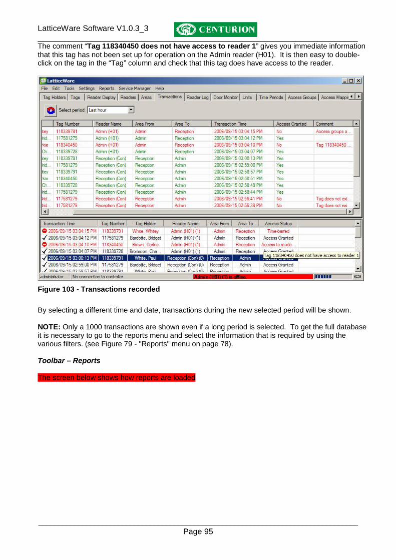
LatticeWare Software V1.0.3_3 ________________________________________________________________________
________________________________________________________________________________ Page 95
The comment “Tag 118340450 does not have access to reader 1” gives you immediate information that this tag has not been set up for operation on the Admin reader (H01). It is then easy to double-click on the tag in the “Tag” column and check that this tag does have access to the reader.
Figure 103 - Transactions recorded By selecting a different time and date, transactions during the new selected period will be shown. NOTE: Only a 1000 transactions are shown even if a long period is selected. To get the full database it is necessary to go to the reports menu and select the information that is required by using the various filters. (see Figure 79 - "Reports" menu on page 78). Toolbar – Reports The screen below shows how reports are loaded

LatticeWare Software V1.0.3_3 ________________________________________________________________________
________________________________________________________________________________ Page 96
Company Details Additional information on this and other products can be obtained from: Centurion Systems (Pty) Ltd P O Box 506 Cramerview 2060 South Africa 148 Epsom Avenue North Riding Gauteng Tel: +27 (11) 699 2400 Fax: +27 (11) 704 3412 Email: [email protected] Web: www.centsys.co.za


