Embed Size (px)
Citation preview
ECCM16 - 16TH
EUROPEAN CONFERENCE ON COMPOSITE MATERIALS, Seville, Spain, 22-26 June 2014
1
LATTICE COMPOSITE STRUCTURE DEVELOPMENT FOR SMALL
AIRCRAFT; WASIS
R. Cordero
a*, M. Aversano
b
aCidaut Foundation, Parque Tecnológico de Boecillo, Valladolid, Spain
bPiaggio Aero Industries S.p.A. 80078 Pozzuoli, Italy
Keywords: insertion loss, sound power radiation, SEA, composite panel, composite fuselage
section.
Abstract
An introduction to the EU funded research project WASIS (Wafer design Approach for Safety
Increasing in worst case Situations and joints minimizing) is given in this paper, including
work performed and results obtained by the whole project consortium. Development of a
wafer like structure designed as a fiber reinforced lattice composite is accomplished, aiming
to replace a conventional metallic fuselage section of a small airplane with an alternative
Carbon Fiber Reinforced Plastic (CFRP). WASIS project aims to achieve the challenge of
“More Affordable, Safer, Cleaner and Quieter” aircrafts, developing a composite fuselage
structure based on the lattice stiffening concept and optimizing geometrical and mass
properties of transition zones of fuselage structural joints. Main project activities covered the
full scale fuselage section design based on downscaled prototypes, as well as setting up
manufacturing processes for two alternative methods; filament winding and tape placement.
Analytical and numerical calculations guide the development process, and are validated
through dedicated tests before leading to the final fuselage section design. Besides low weight
and automatic manufacturing aspects, safety is a main concern during design, accounting for
composite structure performance under several impact load cases. Special attention is given
to vibroacoustic performance of test panels and fuselage section, with a dedicated study to
virtually assess the acoustic field inside the composite fuselage section under operational
conditions.
1. Introduction
The EU funded research project WASIS (Wafer design Approach for Safety Increasing in
worst case Situations and joints minimizing) is presented in this paper, covering the work
performed by the whole project consortium. WASIS project aims to achieve the challenge of
“More Affordable, Safer, Cleaner and Quieter” aircrafts, developing a composite fuselage
structure based on the lattice stiffening concept and optimizing geometrical and mass
properties of transition zones of fuselage structural joints. After an introduction of the
components that are designed and manufactured, a more detailed study of the vibro-acoustic

ECCM16 - 16TH
EUROPEAN CONFERENCE ON COMPOSITE MATERIALS, Seville, Spain, 22-26 June 2014
2
performance of composite parts including the development of a Statistical Energy Analysis
model is covered.
Figure 1. Piaggio Aero P-180. Avanti aircraft with WASIS lattice fuselage section superposed
2. Panel and Fuselage section design
2.1. Test panels design
According to the standard procedure followed in new structures development, test
specifications have to be accurately defined before structure design and manufacturing. That
is why final parameters of wafer barrel have to be grounded on results of sub-components
testing. Before attempting to manufacture the wafer fuselage section, test panels
representative of a fuselage part were designed to clarify some structure and manufacturing
requirements. Typical representative sub-component for cylindrical fuselage section is panel
as a part of full-scale and small-scale barrels with and without opening (illuminator, lid etc)
having the same load-carrying structure and radius as real barrel. Therefore possible variants
of testing panels’ load-carrying schemes and dimensions were developed. Test panel’s wafer
structure and ribs cross-section geometry within this “working area” correspond completely to
the wafer fuselage section design (26º/90º). Two test panel configurations were addressed:
• Regular wafer panel, used to account for generation of wafer structure during the
manufacturing stage and test panel joining with specific jig, so that it can be fixed to
the test machine grips (reels number and position)
• Wafer panel with opening. Opening configuration and dimensions were selected to
ensure optimal loads transfer and distribution within the panel, and continuous
generation of lattice structure and opening reinforcing frame.
To ensure test panel manufacturability at ribs intersection, details of fibers intersection at ribs
were defined including fillet radii.
2.1. Fuselage section design
From initial wafer design results obtained with analytical models, specific aspects of the
wafer structure design were addressed. In particular deep wafer fuselage section analysis
including ribs/reels quantity, winding scheme and ribs geometry. Due to budget limitation,
instead of manufacturing a full scale fuselage section of 1.8m in diameter and 2m length
ECCM16 - 16TH
EUROPEAN CONFERENCE ON COMPOSITE MATERIALS, Seville, Spain, 22-26 June 2014
3
(corresponding to the P-180 aircraft), design and manufacturing tasks of the wafer structure
are being carried out at two scaled down levels:
• Small prototype design (0.5m diameter): Based on the developed requirements and
similarity criteria small-scaled prototype was designed for further wafer section study
and testing as well as all possible bottlenecks in integral structure manufacturing
identification.
• Large prototype design (1m diameter): Based on detailed analysis of small prototype
design, manufacturing and testing, as well as taking into account results of wafer
section safety assessment and corrective design measures, large-scale prototype was
designed to demonstrate WASIS integral approach of fuselage section development.
As a reference, optimised metallic fuselage sections were calculated, weighting:
• Monocoque: 73.63 kg for aluminium alloy and 101.44 kg for titanium alloy.
• Semi-monocoque: 60.15 kg for aluminium alloy and 169.2 kg for titanium alloy
Thus variant of aluminium monocoque section was selected as reference prototype for further
comparison because it is the lightest and more realistic. For the composite wafer structure
three alternative rib winding patterns were compared, changing the number of mandrel
revolutions per stroke of laying device. For those three design patterns, ribs orientation angles
and ratio between layers having different orientation angles, (i.e. package stacking sequence)
were taken into account. Eventually a trapezoidal cross section shape of spiral and hoop ribs
was designed, and its geometrical parameters optimised. For each prototype scaled version,
ribs/reels quantity, winding scheme and ribs geometry was obtained. Ribs cross-section
geometry was achieved balancing between manufacturing requirements (trapeze angle is
critical for wafer structure extraction from silicon mould) and uniform distribution of load,
transferred from rib to reels, fixed on attachment frame. As result – ribs cross section with
trapeze angle 5° was found as optimal. The final design versions before validation tests
passed a final checking, using typical limitations of material ultimate strength (60% of
knocking down factors) and deformations (less than 3000 microstrains maximum deformation
in the 1st direction). Once the fuselage section design was closed, floor fittings for floor
attachment were designed.
3. Manufactured prototypes
3.1. INEGI test panel
Upon completion of the real scale wafer-structure design based on predefined requirements,
guaranteed its manufacturability and considered respective setups to different scales, INEGI
proceeded with its implementation. In order to have a preliminary assessment of
manufacturing difficulties, understanding and results about the match between the expected
behaviour and the one resulted from tests INEGI manufactured a wafer Test Panel, which is a
section of the real scale wafer-structure.

ECCM16 - 16TH
EUROPEAN CONFERENCE ON COMPOSITE MATERIALS, Seville, Spain, 22-26 June 2014
4
Figure 2. Test panel on the left side and fuselage section on the right hand
3.2. CIRCOMP fuselage section
The larger prototype, a demonstrator manufactured by CirComp for proving of the concept of
filament winding, is a fuselage section of 1m diameter and 2m length. It includes
technological advances of the project and will be used for non destructive static testing. In
contrary with the test panel, fuselage section is not real scale, and will not be implemented for
real use. The main purpose for being manufactured is to validate the designed technologies
and the manufacturing processes with their respective toolings, and test the prototypes
afterwards, including vibro-acoustic characterisation. The main work was related to the wafer
section manufacturing design, specially the manufacturing process set up. Parts of the set-up
of the manufacturing process had been carried out. The filament winding set up of the
machine with the special tooling to integrate the common manufacturing of skin and ribs
together had been performed.
4. Development of fuselage section vibroacoustic model
Composite structures represent today a valid alternative to conventional metal airframe
architecture thanks to both the high stiffness to weight ratio and to manufacturing advantages
in terms of parts saving. Unfortunately, despite these known benefits, its application could be
limited due to drawbacks related to the poor vibro-acoustic performances. Indeed, it is known
that high stiffness and low weight of such structures could result in supersonic propagation of
bending and shear waves at low frequencies and high frequencies, respectively, finally
resulting in a severe decrease in transmission loss properties. So far, although much research
has been performed on the conventional composite fuselage to reduce the interior noise level
of the cabin, it is very rare to find a scientific literature referred to composite fuselage with
geodesic stiffening approach. Then, on the basis of these considerations a deeper investigation
on vibro-acoustic performances of such fuselage design approach will be conducted and then
compared with conventional metal architecture based on aluminum skins and frames
stiffening. Thus the aim of this comparative study is to gain understanding on the vibro
acoustic performance of composite fuselage with lattice structural architecture with respect to
conventional metal airframe with frame stiffening as that adopted by Piaggio P.180 business
aircraft. To reach this goal both numerical and experimental activities were accomplished.
The dynamic performance of a structure is primarily determined by its weight, bending
stiffness and loss factors. The acoustic properties like sound radiation ratio and sound
ECCM16 - 16TH
EUROPEAN CONFERENCE ON COMPOSITE MATERIALS, Seville, Spain, 22-26 June 2014
5
transmission loss are determined by the dynamic properties and dimensions of the structure.
For the validation of any theoretical model for the prediction of the acoustic properties of a
structure all its basic dynamic properties must be known. Once these parameters have been
determined through experimental measurements any theoretical model predicting the acoustic
properties of more complicated structures can be validated. On these premises, at first a
method to model composite wafer structures with the Statistical Energy Analysis (SEA)
method was developed and validated through correlation with experimental measurements
carried out both on a single test article of a composite wafer panel and then on a composite
wafer fuselage section. Besides, two full scale SEA models based on the fuselage section of a
P.180 aircraft were developed aiming to characterize its vibro acoustics behavior. In
particular, the former numerical test rig represents a conventional metal structure with frame
stiffening while the latter is a full scale, structurally equivalent, composite fuselage with
lattice stiffening. Finally, a conclusive assessment, highlighting advantages and disadvantages
of each design approach is presented. Next a detailed description of numerical and
experimental activities is described.
4.1. Model development
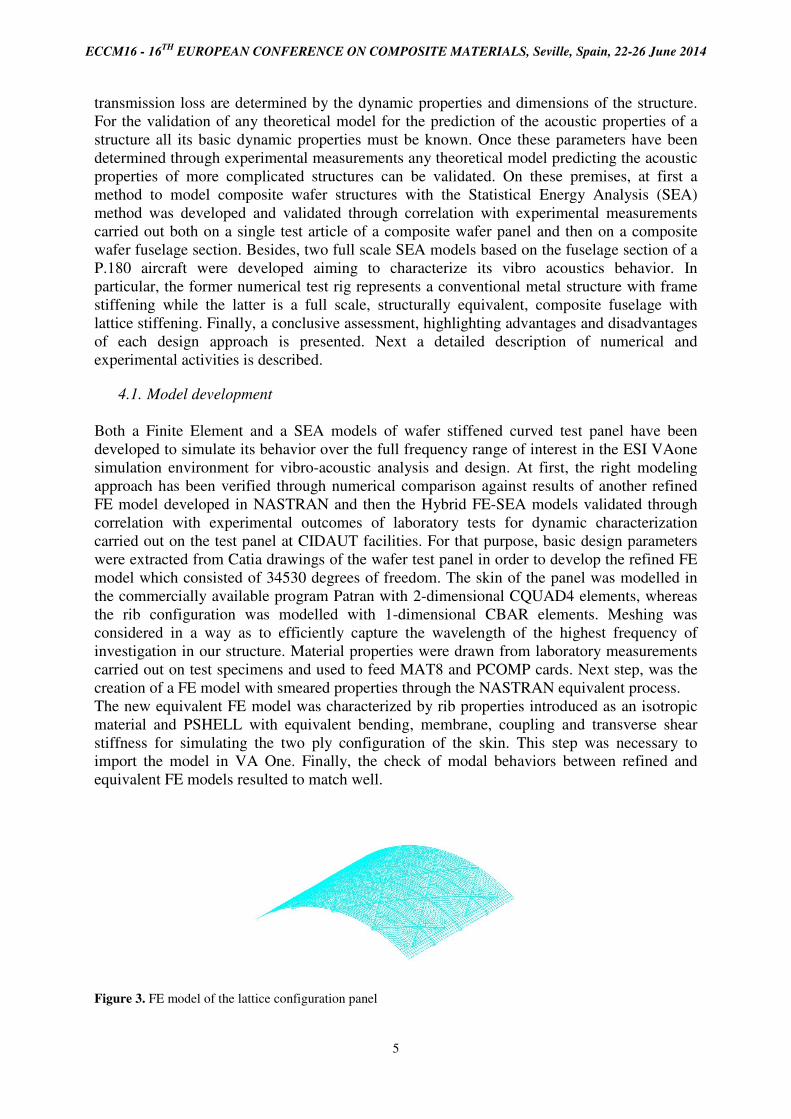
Both a Finite Element and a SEA models of wafer stiffened curved test panel have been
developed to simulate its behavior over the full frequency range of interest in the ESI VAone
simulation environment for vibro-acoustic analysis and design. At first, the right modeling
approach has been verified through numerical comparison against results of another refined
FE model developed in NASTRAN and then the Hybrid FE-SEA models validated through
correlation with experimental outcomes of laboratory tests for dynamic characterization
carried out on the test panel at CIDAUT facilities. For that purpose, basic design parameters
were extracted from Catia drawings of the wafer test panel in order to develop the refined FE
model which consisted of 34530 degrees of freedom. The skin of the panel was modelled in
the commercially available program Patran with 2-dimensional CQUAD4 elements, whereas
the rib configuration was modelled with 1-dimensional CBAR elements. Meshing was
considered in a way as to efficiently capture the wavelength of the highest frequency of
investigation in our structure. Material properties were drawn from laboratory measurements
carried out on test specimens and used to feed MAT8 and PCOMP cards. Next step, was the
creation of a FE model with smeared properties through the NASTRAN equivalent process.
The new equivalent FE model was characterized by rib properties introduced as an isotropic
material and PSHELL with equivalent bending, membrane, coupling and transverse shear
stiffness for simulating the two ply configuration of the skin. This step was necessary to
import the model in VA One. Finally, the check of modal behaviors between refined and
equivalent FE models resulted to match well.
Figure 3. FE model of the lattice configuration panel

ECCM16 - 16TH
EUROPEAN CONFERENCE ON COMPOSITE MATERIALS, Seville, Spain, 22-26 June 2014
6
A SEA model was later developed with 42 SEA “composite plates” of “orthotropic material”,
joined together with 17 SEA isotropic “beam” subsystems having the same properties as
equivalent FE NASTRAN model.
Figure 4. SEA model of the lattice configuration panel
4.1. Vibroacoustic characterisation tests
Vibro Acoustic characterization of the composite panel. The composite wafer panel
developed and manufactured previously in WASIS was tested. Experiments on that panel
included modal analysis aimed to identify resonance frequencies, modal shapes, structural
damping loss factor and bending stiffness of the structure. In addition a number of frequency
response functions (FRFs) were determined. Panels manufactured by the consortium
corresponds to two different manufacturing methods, the one from INEGI is manufactured
with filament winding while the one from IVW was made with automatic tape placement. The
one from INEGI was selected for the study because the manufacturing method is shared
between both panel and fuselage section. The panel study started with frequency response
functions (FRF) in order to identify first natural frequencies of the panel corresponding to its
modes of resonance and what the modal density of the panel is. According to the dimensions
of the panel, its stiffness and weight, it was highly probable that its first resonances were at
higher frequencies than its equivalent metallic counterpart. The composite panel FRF
consisted of 5 excitation points and 8 measurement points. The panel was hanged with elastic
ropes to reproduce free boundary conditions. The structure was excited by an impact hammer
in 5 points and the response was registered with accelerometers and a laser vibrometer, being
the 8 measurement points evenly distributed over the sample surface. After that the panel
radiation properties where characterized through the panel radiation factor. In this test the
panel, still with free boundary conditions, was excited by a shaker. In order to represent the
actual use conditions, i.e. excitation equivalent to flight loads, loads were introduced through
the external surface (corresponding to the shell, namely, the airplane external side) and the
emitted noise was measured in the inner side (where the lattice structure is facing the interior
of the airplane). To calculate the radiation factor the sound power and the vibration energy of
panel were measured. Eventually the last test on the INEGI panel is the measurement of its
transmission loss (TL). Depending on the modal behavior of the panel, two alternatives were
proposed: (1) if first panel resonance is found at “high” frequency, the TL is measured
between a small reverberant chamber (loading the panel with a diffuse sound field on one
side) and an hemi-anechoic chamber (to allow sound radiation in free field conditions on the
opposite side). Figure 5 shows the small reverberant chamber used to measure TL.

ECCM16 - 16TH
EUROPEAN CONFERENCE ON COMPOSITE MATERIALS, Seville, Spain, 22-26 June 2014
7
Figure 5. Small reverberant chamber used for composite panel transmission loss characterisation.
To measure TL with this facility a grid of microphones on the receiver side is set up, with
which sound power radiated by the panel is calculated, while emitted sound power inside the
small reverberant chamber is measured as well. (2) if the panel vibration behavior shows that
the aforementioned hypothesis is not correct, TL is measured between a larger reverberant
room and the hemi-anechoic chamber. Figure 6 shows the facility proposed to measure TL
between an hemi-anechoic chamber and a diffuse chamber.
Figure 6. In the left side, we can see an specimen (not the composite panel) in the test window, as seen from the
hemi-anechoic side together with a grid of microphones. In the right side the diffuse chamber.

ECCM16 - 16TH
EUROPEAN CONFERENCE ON COMPOSITE MATERIALS, Seville, Spain, 22-26 June 2014
8
TL is tested in two configurations, changing the receiver and emitting surfaces, in order to
investigate whether the transmission properties of the sample are symmetrical or not. The aim
of this study is to investigate which configuration is more convenient for the equivalent
characterisation of the barrel. If the composite panel behaves equally in terms of sound
transmission regardless the receiver and emitter side, then the preferred set up to characterise
the transmission of sound performance of the composite barrel is to create a reverberant field
outside and measure the transmitted sound inside. Otherwise it is the opposite
Vibro Acoustic characterization of the Wafer Fuselage barrel. The half scale composite
fuselage barrel with wafer stiffening manufactured in WASIS was hanged through its metallic
attachment frame with suitable suspenders in the hemi-anechoic chamber to simulate free
boundary conditions, in a similar fashion as it was done with the composite panel. Two
suitable wooden caps were manufactured to create a closed volume with the purpose of
allowing acoustic loading and measurements. In order to characterize the vibro acoustic
behavior of this component, its main acoustic properties like sound transmission loss, sound
radiation ratio and loss factor are determined. In addition a number of FRFs are measured
while the fuselage barrel is acoustically excited with loudspeakers and mechanically with
shakers. The component dynamic response is measured with microphones and
accelerometers, then recorded signals are analyzed to provide baseline for correlation with
numerical outcomes. Thus tests on the fuselage section start with FRFs, in which the same
setup as the one described for the panel tests is used. Then the fuselage section radiation
performance is characterised. In this case, adding a couple of wooden caps, a closed volume is
obtained inside the barrel cavity. Then we assume the hypothesis that this interior cavity
behaves as a reverberant chamber, which is necessary to calculate the barrel radiation
coefficient. After that the fuselage section TL is measured. As explained before, depending on
the results of the sound transmission in the panel, two alternative set ups were foreseen. If the
panel behaves equally in terms of sound transmission from both sides, then the TL test is done
introducing an acoustic source in the barrel cavity and measuring the sound power outside.
This test is carried out in the hemi-anechoic chamber. But if the sound transmission is found
to be different depending on the emitter and receiver sides, the best way to simulate the real
loading condition is to reproduce a diffuse sound field outside the barrel. In doing so the test
is carried out in a reverberant chamber, and the sound transmitted to the interior is measured.
5. Conclusions
An introduction to the design and manufacturing process carried out in the WASIS project for
composite parts for aeronautic application is shown. Apart from the mechanical performance,
a study is presented to characterize the vibro-acoustic performance of such components.
6. Acknowledgments
This work was developed inside WASIS Project, supported by European Union. The authors
would like to thank the WASIS consortium and acknowledge the support from the European
Community‘s Seventh Framework Programme AAT.2010.1.1-2. AAT.2010.4.1-2. TPT under
grant agreement n° 2655494