Embed Size (px)
Citation preview

H4T Lathe CNC Controller
Manual April,2005

TABLE OF CONTENTS
0 - 1
TABLE OF CONTENTS 1 MAIN FEATURES OF LATHE CNC CONTROLLER 1-1
2 INSTRUCTION 2-1
2.1 Basic Instructions 2-1 Power-On Display 2-1 Standby Display 2-1 Auto Mode Display 2-2 MDI Mode Display 2-3 Home Origin Mode Display 2-3 Jog Mode display 2-4 Edit Mode display 2-5 Program Mode Display 2-6 I/O Mode Display 2-8 Tool Compensation Display 2-9 MCM Display 2-10 Error&Software Version Time 2-11 System parameter 2-12 Graphic mode 2-14 2.2 Program Edition 2-15 2.2.1 Programming Introduction 2-15 2.2.1.1 Part Program 2-15 2.2.1.2 Methods Of Programming 2-15 2.2.1.3 The Composition of A Part Program 2-16 2.2.1.4 Coordinate System 2-19 Cartesian Coordinate System 2-19 Coordinate of Tool Position Command (Coordinate) 2-20 Work Origin/Work Coordinate 2-22 Machine Origin (HOME Location) 2-23 2.2.1.5 Control Range 2-24 2.2.2 Program Editing 2-25 2.2.2.1 Program Selection 2-25 2.2.2.2 New Program Editing 2-26 2.2.2.3 Program Revision 2-29 2.2.2.4 Rules for Numerical Input 2-33 2.2.2.5 Notes on Program Edit 2-34

HUST CNC H4T MANUAL
0 - 2
3 PREPARATORY FUNCTION (G/M FUNCTION) 3-1 3.1 Explanations 3-1 3.2 Positioning (Rapid Traverse), G00 3-3 3.3 Linear Interpolation (Cutting Feed), G01 3-4 3.4 Circular Interpolation, G02 & G03 3-5 3.5 Temporary Hold (Stop, Dwell), G04 3-8 3.6 Clear Machine Coordinates, G08 3-9 3.7 Move To The First Reference Point, G28 3-9 3.8 Return To The Previous Location From The Reference Point, G29
3-10 3.9 Move To The Second (2nd) Reference Point, G30 3-10 3.10 Skip Function, G31 3-10 3.11 Thread Cutting Command, G32 3-11 3.12 Tape Cutting Canned Cycle G33 3-13 3.13 Canned Cycle Functions (Pattern Functions) 3-14 3.13.1 Single Canned Cycle, G90, G92, G94 3-17 3.13.2 Compound Canned Cycle Functions, G70~G76 3-19 3.14 Max. Spindle Speed Setting, G50 3-30 3.15 Constant Surface Cutting Speed Setting, G96 3-30 3.16 Constant RPM Setting (Constant Surface Cutting Speed Cancel), G97
3-31 3.17 Cutting Feed-rate Setting, G98, G99 3-31 3.18 Metric/ Non-metric measuring System Conversion, G20 G21 3-31 3.19 Auxiliary Functions, M-codes, S-codes 3-31 3.20 Sub-program 3-32 3.21 Total Offset Compensation Set and Cancel 3-33 3.22 Tool-tip Radius Compensation Command, G40,G41,G42 3-36 4 MCM PARAMETERS 4-1
4.1 MCM Parameter 4-1 4.1.1 Basic Description 4-1 4.1.2 Machine Constant Parameter 4-1 4.2 Parameter Description 4-3

TABLE OF CONTENTS
0 - 3
5 CONNECTIONS 5-1 5.1 Connecting System Descriptions 5-1 5.2 System Installation 5-2 5.2.1 Ambient Surroundings 5-2 5.2.2 Cabinet Considerations 5-2 5.2.3 Thermal Design in the Cabinet 5-3 5.2.4 External Dimensions and Diagrams 5-4 H4T Keyboard Panel and LCD Screen 5-4 H4T CPU Main Board Connectors (Rear View) 5-5 Dimension for H4T Controller Box (Rear view) 5-6 Dimension for H4T Controller Box (Front view) 5-6 Cutout Dimension for H4T Controller Installation 5-7 5.3 Input/Output Interface Connection (I/O) 5-8 5.3.1 Input Board / Output Board –Terminal Block Type 5-8 NPN Type Standard Input Board (I bit)-24 IN 5-8 NPN Type Standard Output Board (O bit)-16 OUT 5-8 5.3.2 Input Board/Output Board- CE Rules 5-9 Input Board 5-9 Output Relay Board 5-10 5.3.3 I/O Interface Connecting Arrangement 5-11 5.3.4 Input Signals 5-12 Input Signal Type 5-12 Input Connecting Diagram (Direct Input Controller) 5-12 Input Connecting Diagram (I bit Input Controller) 5-13 5.3.5 Output Signals 5-13 Output Signal Type 5-13 Output Connecting Diagram (Direct Output to Machine) 5-13 Output Connecting Diagram (Output Board to Machine) 5-13 5.4 Connecting Diagrams 5-14 5.4.1 Connector types 5-14 5.4.2 Indicated numbered connectors 5-14 5.4.3 H4T Connection (Terminal Block) 5-15 H4T Main Connecting Diagrams 5-15 Emergency-Stop Circuit-1 (Advised Connecting Diagrams) 5-16 Emergency-Stop Circuit-2 (Simplified Connecting Diagrams) 5-17 H4T Spindle Connection 5-18 5.4.4 H4T Connections (C.E. Style Connectors) 5-19
HUST CNC H4T MANUAL
0 - 4
H4T Main Connecting Diagrams 5-19 Emergency-Stop Circuit-1 (Advised Connecting Diagrams) 5-20 Emergency-Stop Circuit-2 (Simplified Connecting Diagrams) 5-21 Servo motor Connections (Mitsubishi J2S Motor) 5-22 5.4.5 Motion Control (Servo/MPG) Connection (Suitable Machine: H4T) 5-23 5.4.6 AC Power System Connector 5-24 5.4.7 MPG Hand-wheel Connecting Diagram 5-24 5.4.8 RS232 Connector Pin Assignment and Connecting Diagram 5-25 6 ERROR MESSAGES 6-1
7 APPENDIX 7-1
Input Arrangement 7-1 Output Arrangement 7-2 M-Code Versus I/O 7-2 Compound Canned Cycle Parameters 7-3 PLC Parameters 7-3

1 MAIN FEATURES
1 - 1
1 MAIN FEATURES OF LATHE CNC CONTROLLER
Controlled Axis: X, Z and Spindle Encoder Feedback Program Designed by CAD/CAM on PC. Program input and DNC on-line
execution from PC through RS232C interface. Memory Capacity for CNC main board - 512k. Battery Backup for CNC program storage in case of power-off. Backlash error compensation for worn lead screw. Provide 40 sets of tool length offset. Self-designed MACRO Program. Tool feed rate can be a millimeter per minute or a millimeter each turn. Single block and continuous commands. Option Skip functions. Option Stop and Feed hold functions. Simultaneous use of absolute and incremental coordinate in the program. Self-diagnostic and error signaling function. Direct use of “ R”, “ I” and “ J” incremental value for radius in circular
cutting. MPG hand-wheel test and collision free function for cutting product at the
speed controller by MPG. Equipped with 24 standard programmable inputs and 16 outputs.
This operator’s manual includes program editing, G/M code, parameter settings, connections and maintenance (plus warn descriptions) with examples and explanations for each command instruction. If there are any problems in application, please fill out a problem sheet indicating the natures of the problem. Send it by either fax or mail. We will respond to you as soon as possible.

HUST CNC H4T MANUAL
1 - 2

H4 LATHE OPERATION MANUAL
2 - 1
2 INSTRUCTION 2.1 Basic Instructions Operating Diagrams
Power-on Display You will see this image after the power is on like the illustration below:
Fig.2-1
Standby Display
After 3 seconds, you will enter the standby display. You can also obtain the same image when you press “Reset” key like the image below:
Fig.2-2
Auto Mode Display

H4 LATHE OPERATION MANUAL
2 - 2
Press key “ Auto/ MDI” to enter the auto mode, the display is shown below:
Figure 2-3
Soft keys under the auto mode: 1. Program Feed-Hold: only valid during the program operation.
In the program operation, press the key and the program will stop immediately. You can continue operating the program by press this soft key again or CYCST key.
2. Single Step Execution: users can select the function any time without being limited in the state of operation or stop. This function can only carry one step by each key press of restart instead of executing the whole program continuously.
3. Program Restart: only can be selected before the program execution. When the program restart is being selected, it will continue the task from the previous single block where it stopped. Users can search the stopped single block or reset the block in the editing display.
4. MPG - TEST: users can select the function any time without being limited in the state of operation or stop. When the function is being selected, the movement of all the axis in the program can only be controlled by MPG. If there is no input of MPG, the axis will stop moving. The users can also use manual key 『X+』、『Z-』press to replace MPG.
5. Option Stop: only can be selected before the program execution. When option stop is being selected, M01 commend in the program will be considered as a stop commend. It is meaningless if M01 is not selected.
Part numbers: each execution to M15 will add on one and execution to M16 will return to zero. If users need to return to zero manually, please press the

H4 LATHE OPERATION MANUAL
2 - 3
“0” key twice immediately to return zero. ※When part numbers reach to the parameter counting limit, O13 will output. Part time: show the current executing time. After each program end or stop, it will automatically return to zero when it restarts.
MDI Mode Display Press 『 Auto/ MDI』key twice to enter the MDI mode, the display is shown below:
Fig.2-4
Home Origin Mode Display Press 『JOG/HOME』key twice to enter the home origin mode, the display is shown below: H4-T display
Fig. 2-5
Methods for returning the origin: 1. Select the axis: there are some ways to select the axis. You can either
press the English letter “ X ”, “ Z “ on the right of the screen directly or

H4 LATHE OPERATION MANUAL
2 - 4
press the key button” X+’, “X-“, “Z+”, “Z-“ to make your selection. 2. Press” CYCST” key
Note: X and Z- axis will be displayed as reversal colors on the screen once they are selected. The initialized screen display is set Z-axis for its starting of origin mode.
Jog Mode display
Press『JOG/HOME』key to enter jog mode, the display is shown below:
Fig.2-6
There are several functions under the jog mode: 1. Axis positioning:(Three types of positioning)
a. Manual jog: select the axis (see the note of home origin mode for reference) to turn the jog. The jog will be in valid if the axis is not selected.
b. Continuous movement: (Single step function is not on) Continuously press “X+” key and X-axis will do positive movement, X-axis will do negative movement. Z-axis is followed the same way.
c. Move single step: Select your desired distance for each single step such as 0.001,0.01,0.1,1 and press X+, X-, Z+,Z-. The system will follow the selection to make the step.
Note: Press the key once more it returns back to continue jog mode.

H4 LATHE OPERATION MANUAL
2 - 5
2. Manual Switch: a. Spindle: Clockwise, Counter Clockwise, Stop. b. Coolant: Press on and off key c. Lubricant: Press the key and it will be provided after 1 second.
LED is the indicator for the operation.
Edit Mode display Press “Edit/PRNO” to enter the edit mode, the display is shown below:
Fig.2-7 This screen mode can be edited directly (Please see the edit chapter for details).
a. Set-Re.N: In program edit mode, use cursor up and down to assign the
single command, press the key, then return the AUTO mode display. It will execute the assign program when press the『RESTART』key .
b. Last-N: When stop the program(If press the Reset、EM-STOP key …), press this key can find the last executed single program.

H4 LATHE OPERATION MANUAL
2 - 6
Program Mode Display Press twice 『Edit/PRNO』to enter the program mode, the display is shown below:
Fig.2-8 Program selecting methods:
1. Select Program: a. Use cursor up and down or page up and down to select the program
numbers. b. Press the soft key ”Select” or press enter key.
2. Program Note: a. Use cursor up and down or page up and down to select the note
numbers. b. Enter the English letter or number. c. Press enter key.
3. Program Delete: a. Use cursor up and down or page up and down to select the delete
numbers. b. Press delete key, the dialogue box will appear to confirm your
command. Press soft key YES or Y to clear the program. Press NO or N key to cancel the delete program.
4. Program Copy: a. Press” copy” key, it shows as follows:

H4 LATHE OPERATION MANUAL
2 - 7
Fig.2-9
b. Use cursor up and down or page up and down to point at the source program numbers.
c. Press Source key d. Use cursor up and down or page up and down to select the purpose
numbers. e. Press purpose key f. After confirmation for both source and purpose of program numbers,
and press executing key. The copy is complete.

H4 LATHE OPERATION MANUAL
2 - 8
I/O Mode Display Press twice 『GRAPH/ I/O』key to enter I/O mode, the display is shown below:
Fig.2-10
Under this mode it can check the input status of the controller. (Color reversion shows inputting.) Press output soft key, it will cut to the output status display like the figure below:
Fig.2-11
Under this mode it can check the output status of controller. (Color reversion shows outputting.) Press input soft key, it again returns back to input status screen.

H4 LATHE OPERATION MANUAL
2 - 9
Tool Compensation Display Press 『T.Offset』to enter wear compensation directly in the tool compensation mode.
Fig.2-12
Users can utilize the soft key to switch three different screen displays such as tool wear, offset compensations and parameters under this mode. ※Note:that the icon of the PAGE blinks the page can be changed.
1. Ways for parameter setting in tool wear compensation are as follows: a. Utilize the cursors to move to the revising parameter. b. Enter numbers. c. Press enter key.
2. Tool offset compensation display is below:
Fig.2-13

H4 LATHE OPERATION MANUAL
2 - 10
Tool offset compensation setting are as follows: a. Utilized the cursors to move to the revising parameter. b. Enter numbers. c. Press enter key.
3. Parameters display is followed:
Fig.2-14
Fig.2-15
4. When the error occurs, the system will automatically switch to the error dialogue box or press the soft key at the second page of parameter for error messages.

H4 LATHE OPERATION MANUAL
2 - 11
Fig. 2-16
5. Press soft key (Software Version) at the second page of parameter to enter the display of software version as the figure demonstrated below:
Fig.2-17
In the display, it shows the dates of both system and PLC. Example: 2002 1205 stands for the date on December 5th, 2002.
2003 528 stands for the date on May 28th, 2003 and so on. 6. The parameters second page, It can into the page if you press the『SYS-MCM』key. Fig. 2-18 Enter the cipher code, then into the parameters page. Fig. 2-19 You can change the cipher code in this page. Press the『Change the Password』key, then into the password revising page. Fig. 2-20. It will be work if confirm the new password exactly.
※ You can used the zero code to into the parameter page and change the password. If you first into this mode.

H4 LATHE OPERATION MANUAL
2 - 12
Fig.2-18 Fig.2-19 Fig.2-20 * press the key 『T.RADIUS』 to enter the work origin setting: Note that this
is only valid in the state of home origin. Work Origin setting(1) is demonstrated below:

H4 LATHE OPERATION MANUAL
2 - 13
Fig.2-21
Work Origin setting Procedures: 1. Part cutting and memory saving
a. Chuck tighten test for parts. (Either using foot switch or external chuck key switch)
b. Memory saving for X-axis Select axis and use the jog to move the tool for outer cut. Press the key “ SAVE-X ” before the tool of X-axis leaves the cutting coordinate. The path of X-axis in<MACHINE-POSITION>has saved the memory at the path of X-axis in the<SAVE-POSITION>.
c. Memory saving for Z-axis Select axis and use the jog to move the tool for end cut. Press the key “SAVE -Z ” before the tool of Z-axis leaves the cutting coordinate. The path of Z-axis in <MACHINE-POSITION> has saved the memory at the path of Z-axis in the<SAVE-POSITION>.
2. Press soft key “ NEXT-PAGE” to enter the work origin setting (2) as shown
below:
Fig. 2-22

H4 LATHE OPERATION MANUAL
2 - 14
a. Part Measures Remove the tool and take out the part measure dimensions.
b. Group and Size Entries Use cursor up and down to reach the setting position, groups and diameter of X-axis and the length of Z-axis. After entering numbers, press enter.
c. Parameter Reading Enter reading key, the controller will automatically do the calculations and read the results to the actual parameter of tool length compensation. The display shows right after as the figure 2-17 has demonstrated below:
Graphic Mode Display
Single press the key “ Graph/ I/O “ to enter the graph mode display as follows:
Fig. 2-23
Sign “ + “ in the center of the display shows the zero location. Use cursors to move the zero location. Number 256 at the top left corner of the display shows the current graph of horizontal ratio setting. The ratio can also be changed by page up and down. The image can be cleared by pressing the “ CLEAR “ key.

H4 LATHE OPERATION MANUAL
2 - 15
2.2 Program Edition 2.2.1 Programming Introduction 2.2.1.1 Part Program Prior to cutting a machine part by using a CNC cutting tool, a computer program, called a part program, must be created to describe the shape of the parts, which is based on some kind of coordinate system. The cutting tool will then follow these coordinates to do exact cutting. To create a part program, a concise machining plan is a necessity, which includes the coordinates for the machine part, coolant, spindle speed, tool type, I/O-bit, etc.. When design a machining plan, the following factors must be considered:
1. Determine the machining range requirement and select the suitable CNC machine tool.
2. Determine the work-piece loading method and select the appropriate cutting tool and the tool holder.
3. Determine the machining sequence and the tool path. 4. Determine the cutting conditions such as spindle speed (S), federate (F),
coolant, etc. A part program is a group of sequential instructions formulated according to the machining plan. It can be edited either on a personal computer (PC), then transmitted to the CNC controller through RS232C interface or directly on the CNC controller using the editing keys. Lathe can do both. They will be discussed later. 2.2.1.2 Methods Of Programming A CNC controller will execute the commands exactly in accordance with the instructions of the part program. So, the program design is the most important task in the whole CNC machining process. There are two ways to design a CNC part program and are to be briefly described as bellows: I. Manual Programming Manual programming is a process that the whole process is manually done by hand including the coordinate calculations. It follows this sequence.
Machine part drawing.

H4 LATHE OPERATION MANUAL
2 - 16
Part shape description includes coordinate calculations. Computer program design includes spindle speed, feed rate, M-code,
etc.. Keying in the program instructions into the CNC controller or transmitted
from PC. Testing the program.
The coordinate calculation is a simple process if the part shape is composed of straight lines or 90-degree angles. For curve cutting, however, the calculation will be more complicate and trigonometry will be required for correct answers. Once all calculations have been completed, the CNC part program is written in the formats to be discussed later. The main disadvantage of manual programming, particularly when designing for a very complicated part, is time consuming and prone to making errors. In this case, automatic programming becomes more advantageous than the manual methods.
II. Automatic Programming Automatic programming is a process in which the design work included coordinate calculation that is done by computer. It follows this sequence.
Computer added design for part drawing (CAD) Computer added manufacturing for CNC part program (CAM) Transferring program to CNC controller. Testing the program.
By making use of computer’s high speed calculating capability, program designer can communicate with the computer in simple language, to describe the shape, size and cutting sequence of the part. The computer will transfer the motions to the machine tool into a part program, which is then transferred into CNC controller through RS232C interface. This process is called CAD/CAM. It is a necessary tool when designing a part program for a 3-D work-piece. 2.2.1.3 The Composition of A Part Program A complete part program is composed of program blocks, starting with a

H4 LATHE OPERATION MANUAL
2 - 17
program number Oxxx, ended with M2, M30, or M99, and in between with a series of CNC instructions. A CNC instruction is a command to order the cutting tool to move from one location to another with the specified speed, or the peripheral equipment to do some mechanical work. The cutting is done when the cutting tool moves. An example of a complete part program containing nine blocks is as follows: N10 Go X40.000 Z10.000 N20 G00 X30.000 Z5.000 N30 M3 S3000 N40 G1 X10.000 F200 N50 W-5.000 N60 X15.000 Z-10.000 N70 X30.000 W-10.000 N80 G0 X40.000 Z10.000 N90 M5 N100 M2 A block of program can have one to several instructions and it has a general form as follow. The block sequence number "Nxx" can be omitted. If you do not key in the block number, Lathe has a special function "Auto-N" to automatically generate the number for you during or after program editing (see chapter 6). The program execution starts from top to bottom block and has nothing to do with the order of block sequence number. Each instruction starts with an English letter (A~Z), followed by a integer or floating number, depending on what type of instruction the number is associated with. If the number represents a coordinate, it can be positive (+) or negative (-).
N-____G____X(U) ____Z(W) ____F____S____T ____M____
N: block sequence G: function command X, Z: coordinate position command (absolute position command) U, V: coordinate position command (incremental position command) F: Feed rate S: Spindle speed
H4 LATHE OPERATION MANUAL
2 - 18
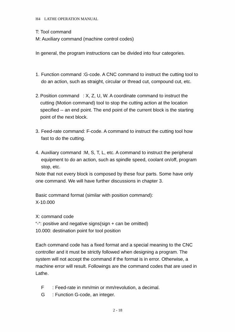
T: Tool command M: Auxiliary command (machine control codes) In general, the program instructions can be divided into four categories. 1. Function command :G-code. A CNC command to instruct the cutting tool to
do an action, such as straight, circular or thread cut, compound cut, etc.
2. Position command : X, Z, U, W. A coordinate command to instruct the cutting (Motion command) tool to stop the cutting action at the location specified -- an end point. The end point of the current block is the starting point of the next block.
3. Feed-rate command: F-code. A command to instruct the cutting tool how fast to do the cutting.
4. Auxiliary command :M, S, T, L, etc. A command to instruct the peripheral equipment to do an action, such as spindle speed, coolant on/off, program stop, etc.
Note that not every block is composed by these four parts. Some have only one command. We will have further discussions in chapter 3. Basic command format (similar with position command): X-10.000 X: command code “-“: positive and negative signs(sign + can be omitted) 10.000: destination point for tool position Each command code has a fixed format and a special meaning to the CNC controller and it must be strictly followed when designing a program. The system will not accept the command if the format is in error. Otherwise, a machine error will result. Followings are the command codes that are used in Lathe.
F : Feed-rate in mm/min or mm/revolution, a decimal. G : Function G-code, an integer.

H4 LATHE OPERATION MANUAL
2 - 19
H : Tool offset compensation number. I : The X-axis component of the arc radius @ the start point, a decimal. K : The Z-axis component of the arc radius @ the start point, a decimal. L : Repetition counter, integer. M : Control code for peripheral machine tool, integer. N : Program block (sequence) number, integer. P : Dwell time; subprogram code; or parameter in canned cycles, integer. Q : Parameter in canned cycles, integer. R : Arc radius or "R" point in canned cycles, decimal. S : Spindle speed, integer. T :Tool commands. U : Incremental coordinate in X-axis, decimal. W : Incremental coordinate in Z-axis, decimal. X : Absolute coordinate in X-axis, decimal. Z : Absolute coordinate in Z-axis, decimal.
Each serial number of program represents a block. Although it is not necessary to use it, it is recommended to utilize the serial numbers for program searching. Lathe has a special function "Auto-N" to automatically generate the number for you during or after program editing (see chapter 6). The program execution starts from top to bottom block and has nothing to do with the order of block sequence number.
Example: N10….…(1) program execution order N30…….(2) N20…….(3) N50…….(4) N40…….(5)
2.2.1.4 Coordinate System The machining action of a cutting tool is accomplished when the tool is moving along a specific path from point A to point B, which represents the shape or the contour of a machine part. In order for the tool to follow the specific path, a computer program describing the shape of the machine part must be created and the shape or the contour is described by the Cartesian coordinate system.

H4 LATHE OPERATION MANUAL
2 - 20
Cartesian Coordinate System Lathe uses the customarily 2-D Cartesian coordinate system as shown in Fig 2-18, with Z-axis being the center of and parallel to the spindle axis and defined as x=0. The other axis is X-axis and Z=0 can be anywhere along the Z-axis at some convenient location for coordinate calculation. The intersecting point of the two axis is the origin, X=0, Z=0. Depending on the location of the cutting tool with respect to the spindle axis, the sign convention of the coordinate system is shown in Fig 2-24. Fig 2-24 Cartesian Coordinate System of CNC Lathe Fig 2-24 is 3-D system (right-hand rule) with the intersecting point designated as origin X=Y=Z=0. The direction of normal rotation for each axis is indicated by the direction of the four fingers when you grab the axis by the right hand with your thumb pointing to the (+) direction of that axis.
Coordinate of Tool Position Command The instruction for tool position command in H4T series can be in either absolute coordinate or incremental coordinate as follows: X, Z: Absolute coordinate command. The cutting tool moves to the position specified by the absolute coordinate X, Z. U, W: Incremental coordinate command. The cutting tool moves to the
position with an incremental amount specified by U, W. Note: Diameter usually stands for X-axis of coordinate in Lathe CNC no matter
it is absolute or incremental.
G03 G02
G02 G03
+Z
+X Tool at the Rear+Z
+X Tool at the Front+Z
M03CW
M04 CCW

H4 LATHE OPERATION MANUAL
2 - 21
Absolute Coordinate The origin is the reference. The coordinates of all points describing the shape of the work-piece (machine part) are calculated from the origin. The coordinates can be positive (+) or negative (-), depending on its relative position with respect to the origin.
Incremental Coordinate The coordinates of all points describing the shape of the work-piece (machine part) are calculated from the end point of the previous block. They are the amount of coordinate increase from the last point. The incremental coordinates can be either positive (+) or negative (-), depending on its relative position with respect to the end point of the previous block. They are positive (+) if the cutting tool is going in the direction of U, W increment, negative (-), otherwise is in the direction of U, W decrement. X, Z, U, W can be mixed in the program. The methods are described below: Absolute Command: P0 to P1---G01 X10.000 F0.200 P0 to P2---X24.000 Z30.000 P2 to P3---X32.000 Z10.000 P3 to P4---Z0.000
Fig.2-25 Absolute Command
10
3038
P3
P2
P1
P0
5
1316
Z
X
P4
X0. ZO.
H4 LATHE OPERATION MANUAL
2 - 22
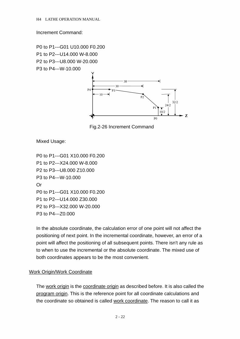
Increment Command: P0 to P1---G01 U10.000 F0.200 P1 to P2---U14.000 W-8.000 P2 to P3---U8.000 W-20.000 P3 to P4---W-10.000
Fig.2-26 Increment Command Mixed Usage: P0 to P1---G01 X10.000 F0.200 P1 to P2---X24.000 W-8.000 P2 to P3---U8.000 Z10.000 P3 to P4---W-10.000 Or P0 to P1---G01 X10.000 F0.200 P1 to P2---U14.000 Z30.000 P2 to P3---X32.000 W-20.000 P3 to P4---Z0.000 In the absolute coordinate, the calculation error of one point will not affect the positioning of next point. In the incremental coordinate, however, an error of a point will affect the positioning of all subsequent points. There isn't any rule as to when to use the incremental or the absolute coordinate. The mixed use of both coordinates appears to be the most convenient.
Work Origin/Work Coordinate
The work origin is the coordinate origin as described before. It is also called the program origin. This is the reference point for all coordinate calculations and the coordinate so obtained is called work coordinate. The reason to call it as
10
3038
P3
P2
P1
P0
10/2
24/2 32/2
Z
X
P4

H4 LATHE OPERATION MANUAL
2 - 23
work origin is to differentiate it from the machine origin to be discussed in the next section. The work origin can be anywhere inside the machine working range. The user should determine the location of this point before making any coordinate calculations. Once the origin is selected, store the coordinate of this point with respect to the machine origin in MCM parameter #1 (see Chap 4). The best selection is the one that will make the coordinate calculation simple and easy. X-axis of Work Origin in Lathe (X=0) should be at the centerline of Spindle. There are three options for Z-axis of work origin: 1. The left end of Z-axis of work origin for its origin. 2. The right end of Z-axis of work origin for its origin. 3. The frontal claw or chuck for Z-axis origin in work origin.
Fig.2-27 Work origin Options (1, 2, 3) It is an equal shape of a complete workpiece to spindle spin in Lathe CNC. Then, it can be made at the other end. Therefore, it only takes half of the workpiece to make in the program like the figure 2-28 below.
Fig.2-28 Workpiece Cut Diagram Machine Origin
The machine origin is the HOME location for the cutting tool. This is the reference point for the coordinate determination of the work origin and the tool offset compensation. The coordinate obtained using the machine origin as calculation base is called the machine coordinate.
Z 21 3
Z

H4 LATHE OPERATION MANUAL
2 - 24
The exact location of the machine origin is determined by the location of the home limit switch on each axis. When user executes X and Z Home on a Lathe CNC controller, the cutting tool will move to the machine origin. The exact distances between the machine origin and the work origin must be accurately measured using a fine instrument, such as a linear scale. Otherwise, the completed part will be in an error. When the electric power is interrupted for any reasons, execute HOME on each axis before resuming any cutting.
Fig.2-29 Machine Origin Diagram
2.2.1.5 Control Range The minimum/maximum programmable range for Lathe CNC controller is as follows. Please note that the control range may be limited by the working range of user's machine.
Metric, mm
Min. setting unit 0.001 Max. setting unit 9999.999 Min. moving unit 0.001 Max. moving unit 9999.999 Max. setting 9999.999
X
Z Machin originZ HOME
Work originX HOME
+Z

H4 LATHE OPERATION MANUAL
2 - 25
Metric Unit / English Unit
G-code G00~G99 (G01=G1) M-code M000~M999 (M01=M1) S-code S1~S9999 rpm F-code 0.001~0~9999.999mm/spin X, Z, U, W, I, K 0.001~+/- 9999.999 mm R (Radius) 0.001~+/- 9999.999 mm G04 0~9999.999 seconds Program number 0~999 T-code 1. There is no tool with two digits, Txx, it is the
number of tool compensation. 2. It has tool with four digits, Txxxx, the first two are
tool selection and the last two are the number of tool compensation
Memory capacity 128 K Lead screw compensation
0~255 pulses (related to tool resolution)
Max. Response Speed 500 KPPS
2.2.2 Program Editing
The following topics will be discussed in this section. 1. Select a program for editing. 2. Edit a new program. 3. Revise an existing program.
2.2.2.1 Program Selection H4T controller can store a maximum of 999 programs with number O0~O999. You can select any one of the programs for editing or execution. The program selection process is described as follow.
H4 LATHE OPERATION MANUAL
2 - 26
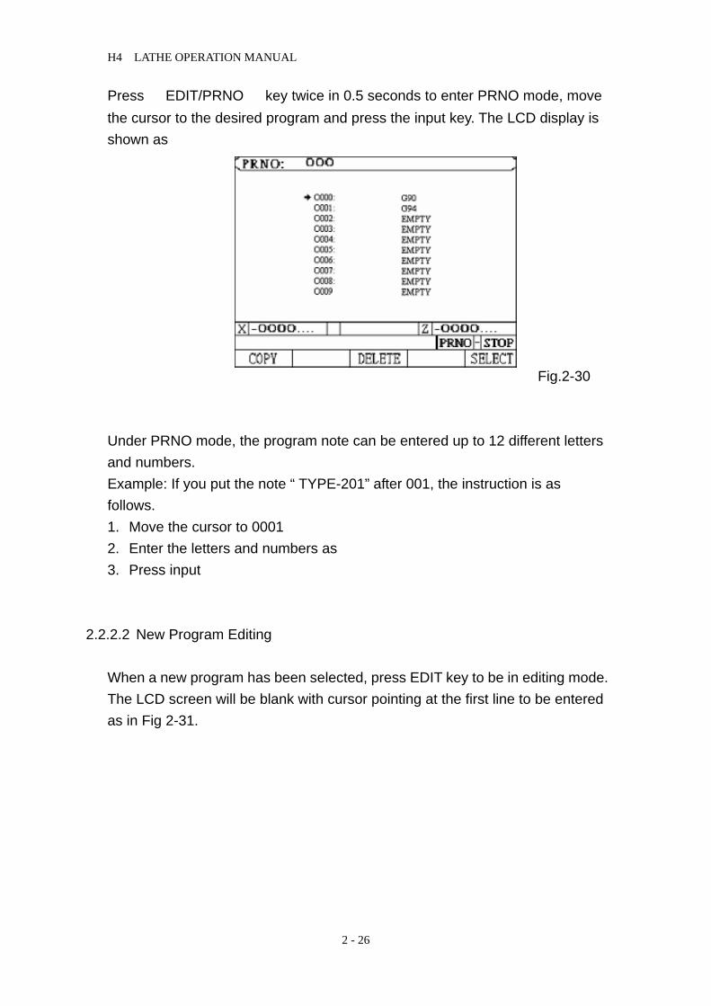
Press 『EDIT/PRNO』 key twice in 0.5 seconds to enter PRNO mode, move the cursor to the desired program and press the input key. The LCD display is shown as
Fig.2-30 Under PRNO mode, the program note can be entered up to 12 different letters and numbers. Example: If you put the note “ TYPE-201” after 001, the instruction is as follows. 1. Move the cursor to 0001 2. Enter the letters and numbers as 3. Press input
2.2.2.2 New Program Editing When a new program has been selected, press EDIT key to be in editing mode. The LCD screen will be blank with cursor pointing at the first line to be entered as in Fig 2-31.

H4 LATHE OPERATION MANUAL
2 - 27
Fig.2-31
During program editing, the following keys will be used.
1. Function keys. 2. Numeric keys, 0~9 3. CURSOR ← and CURSOR → keys for data inspection in the same block. 4. PAGE↑ and PAGE↓ keys for data inspection between lines. 5. NEW LINE key -- Establishing or inserting a new block anywhere in the
program. Key in a function code, then press NEW LINE to establish a new line.
6. INPUT -- For entering a data or a function in the established block. Key in a function code, then use INPUT to enter more data into the established line.
7. DEL -- For deleting a block (line) of program.
Auto-generation of Block Number (Auto-N)
You can edit a program with or without block number. Following is an example program to explain the keystrokes required to edit a new program in the controller. Ex: Program 1 N1 G0 X0. Z0. N2 G4 X1. N3 G0 U480. V-80. N4 G4 X1 N5 M99

H4 LATHE OPERATION MANUAL
2 - 28
Keystrokes: (Ignore the sign "-" below. It's there for clarity) 1. Please confirm the edit status and press Edit key to enter in the controller.
N1 G0 X0. Z0. 2. Enter first block information G – 0 – NEW LINE It is a new establishing block. Thus, users need to enter NEW LINE key. After this step, the LCD screen is shown as Fig 2-26.
Fig.2-32 And enter: X 0 ‧ INPUT Z 0 ‧ INPUT
Key-strokes for the remaining blocks are as follows.
2. N2 G4 X1. (A) G - 4 - NEW LINE
(B) X - 1 - • - INPUT
3. N3 G0 U480. W-480. (A) G - 0 - NEW LINE
(B) U - 4 - 8 - 0 - • - INPUT W- "−" 4 - 8 - 0 - • - INPUT (The negative sign "-" here can be input anywhere before pressing INPUT key)
4. N4 G4 X1.
PRNO: 0
E D I T - S T O P
X 0.000 Z 0.000
G0

H4 LATHE OPERATION MANUAL
2 - 29
(A) G- 4 - NEW LINE (B) X - 1 - • - INPUT
5. N5 M99 (A) M - 99 - NEW LINE
During program editing, you can use CURSOR ←, CURSOR → key to check the input data within the block. Use PAGE↑, PAGE↓ to move up and down the block (line). When you finish editing the entire program, press RESET key to exit.
2.2.2.3 Program Revision
Let's use Program O001 of previous section as our example for program revision. Revise or Add a Function To revise or add a function, simply key in the function code and the correct number, then press INPUT key.
Ex: Revise N3 U480. W-480. To N3 U480. W-480. F0.2
1. Make sure the system in EDIT mode. 2. Use PAGE↑, PAGE↓ key to move cursor to N3 block. 3. Add a function of F0.2. by entering data below and LCD will display as in
Fig 2-33
PRNO: 0
E D I T - S T O P
X 0.000 Z 0.000
N1 X0. Z0.
N2 G4 X1.
N3 U480. W-480. F0.2
N4 G4 X1.
N5 M99

H4 LATHE OPERATION MANUAL
2 - 30
F- 0 - ‧- 2 - INPUT 4. Revise U480. to U360. by keying in
U - 3 – 6 - 0 - • - INPUT Delete a Function To delete a function, simply key in the function to be deleted without number, then press INPUT key. Ex: Revise N30 U480. W-480. F0.2 To N30 U480. W-480. 1. Make sure the system in EDIT mode. 2. Use PAGE↑, PAGE↓ key to move cursor to N3 block. 3. Key "F" without numbers and press INPUT key, LCD displays as Fig 2-28.
Fig.2-34 Insert a Program Block To insert a program block, key in the block number (or any function) and use NEW LINE key to establish the block. Then use INPUT key to input the rest of data for the block.
PRNO: 0
E D I T - S T O P
X 0.000 Z 0.000
N1 X0. Z0.
N2 G4 X1.
N3 U480. W-480.
N4 G4 X1.
N5 M99

H4 LATHE OPERATION MANUAL
2 - 31
Ex: Insert N31 U20. W-20. between N3 G0 U480. W-480. and N4 G4 X1. 1. Make sure the system in EDIT mode. 2. Use PAGE↑, PAGE↓ key to move cursor to N30 block. 4. Enter
N 3 1 new line U 2 0 . input W– 2 0 . input
The LCD display is shown as fig.2-29.
Fig 2-35 Delete a Program Block To delete a block, use PAGE↑, PAGE↓ key to move cursor to the block that you want to delete and press DEL key. For example: Delete N31 U480 W-480. from last example. 1. Make sure the system in EDIT mode. 2. Use PAGE↑, PAGE↓ key to move cursor to N31 block. 3. Press DEL key and the LCD display is as shown in Fig 2-30. (Block N4)
PRNO: 0
E D I T - S T O P
X 0.000 Z 0.000
N1 X0. Z0.
N2 G4 X1.
N3 U480. W-480. F0.2
N31 U20. W-20.
N4 G4 X1
N5 M99

H4 LATHE OPERATION MANUAL
2 - 32
Fig.2-36 Delete a Program Move the cursor to the program that you want to delete it in PRNO mode and press DEL. The LCD display is shown as fig.2-31 Fig.2-37 In the meantime, press Y and clear the content of the 002 program. The key N remains the same. If you want to delete all programs- 0~999, follow the procedures below: Enter MDI mode, and give G10 P2001 command. Then all the content of the program are cleared immediately.
PRNO: 0
E D I T - S T O P
X 0.000 Z 0.000
N1 X0. Z0.
N2 G4 X1.
N3 U480. W-480. F0.2
N4 G4 X1.
N5 M99
PGM-NO.: 0 PGM-REF.:
READY-STOP
X 0.000 Z 0.000
0000: 0001: EMPTY 0002: EMPTY 0003: EMPTY 0004: EMPTY 0005: EMPTY 0006: EMPTY 0007: EMPTY 0008: EMPTY 0009: EMPTY
DELETE O002 (y/n) ?

H4 LATHE OPERATION MANUAL
2 - 33
Note: After completing the procedure, all the program data in memory will be vanished. Therefore, do not use this program if it is not necessary.
2.2.2.4 Rules for Numerical Input
Numerical input has two formats such as integer and decimal with a maximum of 7 digits. If you input the numbers in accordance with the format required by the controller, the number will be entered correctly. You cannot enter a decimal point for a number that requires an integer format. So, the only occasion that may cause error input is the one that you enter an integer for a decimal format. Described more in detail below. The decimal input such as X, Y, I, J is left blank, the content of the controller will automatically move back to the decimal points of last format with dot at front. The table below shows the decimal numbers recognized by the controller after internal process for some integer inputs.
Input 4/3 Format
X2 X0.002 mm
Z35 Z0.035mm
U2500 U2.500 mm
W125. W125.000mm
F300 F0.3 mm/min
The numerical formats for the function codes used in Lathe system are listed below. To avoid any potential error, please use the specified format as follow when key in data. The number "0" after decimal point can be omitted. G, M, N, S-code: Variables Integer input X, Y, Z, U, V, W, I, J-code Decimal input F-code Integer input Note: TO avoid the confusion, apart from integer inputs such G, M, N, S, the rest of the inputs should be entered by decimal points. The number "0" after decimal point can be omitted.

H4 LATHE OPERATION MANUAL
2 - 34
2.2.2.5 Notes on Program Edit Program Block Number 1. Block number N can be omitted, but it’s better to have it for the
convenience of program inspection later. 2. Block number N is recognized by the editing order not by the block
sequence or its value. The numbers by the letter N are merely symbols. For instance, inserting block N35 in Block N30. It will become the following result.
Program 1 N10 G0 X0 Y0 ………first block N20 G4 X1 ……….second block N30 U480 V-480 …….third block N35 U20 V-20 ……….fourth block
N40 G4 X1 …………..fifth block N50 M99……………sixth block
If block N35 is changed to block N350, the arrangement of program execution remains the same. 3. Block number is recognized by the number of characters, not by its value.
Therefore, N10, N010, N0010 are three different block number. Program Block 1. Do not use two G-codes in the same block. If more than one G-code
exists in a block, only the last one is effective. 2. Do not repeat any position code in the same block. The position codes
are X, Y, Z, U, V, I W, J and R. 3. If you specify absolute coordinate and incremental coordinate for the
same axis in a block, only the incremental coordinate will be executed.

H4 LATHE OPERATION MANUAL
2 - 35
Example: G1 X100. U50. -- U50 will be executed. 4. Do not exceed 80 bytes of data input for a single block. Otherwise, the
CNC controller will show an error message Err-08 at the bottom of the screen.

H4 LATHE OPERATION MANUAL
2 - 36

H4 LATHE OPERATION MANUAL
3 - 1
3 PREPARATORY FUNCTION (G FUNCTION) This chapter will discuss the meanings of command codes, such as G, F, M and S-code, and the format of their usage.
3.1 Explanations
G function followed by one (1)or two (2)numbers are special command codes in Lathe system and they are ranging from G00 to G99. The first "0" can be omitted. Each G function has its own specific function as shown in Table 3-1. G-code commands are divided into two groups: 1.One-shot G-codes A One-shot G-code is effective only in the program block where it was encountered. Once program starts executing the next block, it's no longer effective. Example: N10 G0 X30.000 Z40.000 N20 G4 X2.000 .....G04 is one-shot G-code, effective only in this block. N30 X20.000 Z50.000 .....G04 no longer effective in this block. G0 is. 2. Modal G-codes A Modal G-code is a G-code that remains effective until another G-code in the same group is encountered. In Lathe, following G-codes are in the same group. G00, G01, G02, G03 Same group G40, G41, G42 Same group G96, G97 Same group G98, G99 Same group Example: N10 G0 X30.000 Z5.000 .....G0 is effective in this block. N20 X50.000 Z10.000 ....No G-code specified, G0 remains effective. N30 G1 X30.000 F0.2 …. G1 is effective from this block, NOT G0. Normally, only one G-code is allowed in a program block. If several G-codes are accidentally specified in a block, only the last G-code specified is effective. Example: G00 G1 X10.000 ......Only G01 is effective.

H4 LATHE OPERATION MANUAL
3 - 2
Table 3-1 G-Code Definitions
G-code Function * 00 Rapid positioning (fast feed-rate)
* 01# Linear cutting (cutting feed-rate) * 02 Arc cutting, CW (cutter at rear) * 03 Arc cutting, CCW (cutter at rear) 04 Temporary stop 08 Clear machine coordinates in all axis 10 Data input
20 System measurement in INCH mode 21 System measurement in METRIC mode 28 Tool moves to the 1st reference point 29 Moves back to the specified position from the ref. point 30 Tool moves to the 2nd reference point 31 Skip function 32 Thread cutting 33 Taping Cutting Canned Cycle 34 Variable thread cutting
* 40 # Tool radius compensation - cancel * 41 Tool radius compensation - set (left) * 42 Tool radius compensation - set (right)
50 Coordinate system & max. spindle speed setting
70 Canned cycle, fine cut 71 Canned cycle, rough cut, lateral direction 72 Canned cycle, rough cut, traverse direction 73 Contour canned cycle, rough cut 74 Grooving cycle, lateral direction 75 Grooving cycle, traverse direction 76 Canned cycle, thread cut
90 Lateral cutting cycle, single cycle 92 Thread cutting cycle, single cycle 94 Traverse cutting cycle, single cycle
* 96 Setting surface cutting at constant speed * 97 # Canceling surface cutting at constant speed * 98 Feed-rate specified by mm/min or in/min * 99 # Feed-rate specified by mm/revolution or in/revolution
# -- G-codes with "#" are of power-on default setting. * -- G-codes with "*" are modal G-codes.
H4 LATHE OPERATION MANUAL
3 - 3
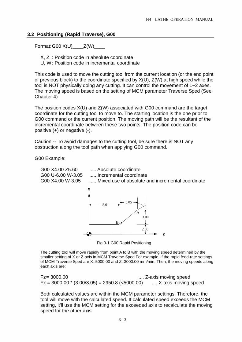
3.2 Positioning (Rapid Traverse), G00 Format: G00 X(U)____Z(W)____ X, Z : Position code in absolute coordinate U, W : Position code in incremental coordinate This code is used to move the cutting tool from the current location (or the end point of previous block) to the coordinate specified by X(U), Z(W) at high speed while the tool is NOT physically doing any cutting. It can control the movement of 1~2 axes. The moving speed is based on the setting of MCM parameter Traverse Sped (See Chapter 4) The position codes X(U) and Z(W) associated with G00 command are the target coordinate for the cutting tool to move to. The starting location is the one prior to G00 command or the current position. The moving path will be the resultant of the incremental coordinate between these two points. The position code can be positive (+) or negative (-). Caution -- To avoid damages to the cutting tool, be sure there is NOT any obstruction along the tool path when applying G00 command. G00 Example: G00 X4.00 Z5.60 ..... Absolute coordinate G00 U-6.00 W-3.05 ..... Incremental coordinate G00 X4.00 W-3.05 ..... Mixed use of absolute and incremental coordinate
Fig 3-1 G00 Rapid Positioning The cutting tool will move rapidly from point A to B with the moving speed determined by the
smaller setting of X or Z-axis in MCM Traverse Sped For example, if the rapid feed-rate settings of MCM Traverse Sped are X=5000.00 and Z=3000.00 mm/min. Then, the moving speeds along each axis are:
Fz = 3000.00 .... Z-axis moving speed Fx = 3000.00 * (3.00/3.05) = 2950.8 (<5000.00) .... X-axis moving speed
Both calculated values are within the MCM parameter settings. Therefore, the tool will move with the calculated speed. If calculated speed exceeds the MCM setting, it'll use the MCM setting for the exceeded axis to recalculate the moving speed for the other axis.
A
B
x
z
5.63.05
3.00
2.00

H4 LATHE OPERATION MANUAL
3 - 4
3.3 Linear Interpolation (Cutting Feed), G01 Format: G01 X(U)____Z(W)____F____ X, Z : Position code in absolute coordinate U, W : Position code in incremental coordinate F : Cutting feed-rate G01 is for the linear cutting motion and can control one to two axes at the same time. The cutting speed is determined by F-code. The smallest setting value for F-code is 0.02 mm/min or 0.2 in/min. F-code can be applied with any G-code including G00 block. However, the G00 moving speed will not be affected by F-code setting. The feed-rate F-code is a modal code. If the cutting rate is a constant for all the program blocks, only one feed-rate in the beginning block needs to be defined and omit the rest. Unless the feed-rate is redefined, the F-code remains effective. The formula of cutting speed calculation for each axis is as below. U and W are incremental values.
Feed-rate in X-axis, Fx UU W
F=+2 2
* (1)
Feed-rate in Z-axis, Fz WU W
F=+2 2
* (2)
Example: Current position at X=2.0, Z=4.60 and F-code in mm/revolution. G01 X4.00 Z2.01 F0.30 ..... Absolute coordinate G01 U2.00 W-2.59 F0.30 ..... Incremental coordinate
Fig 3-2 G01 Example
2.01
4.60 1.00Z
X
B
A

H4 LATHE OPERATION MANUAL
3 - 5
3.4 Circular Interpolation, G02 & G03
Four (4) elements are required to do a circular cutting:
1. Arc cutting command code -- G02 or G03. Depending on the location of the cutting tool with respect to the spindle axis, the direction of circular cutting path is defined by command codes G02 and G03 and the definitions of G02 and G03 are defined as in the figure below:
Fig 3-3 Directions of G02 and G03
Command Description 1 Circular interpolative direction G02
G03 Clockwise
Counter clockwise 2 The end point of
arc Absolute
Incremental X Z U W
Absolute coordinate Arc to the end incremental
3 The center of arc I K R
I=X-axis, K=Z-axis Radius
range –4000.~4000.mm4 Arc cutting rate F The minimum setting
0.2mm/per turn
Tool at Top Rear Tool at Bottom Front G02 Clockwise Counter clockwise G03 Counter clockwise Clockwise
G0
X
Z G0
X
Z
Tool at the Rear
CW CCW G0
X
ZG0
X
Z
Tool at the Front
CW CCW

H4 LATHE OPERATION MANUAL
3 - 6
2. The end point of the arc -- X(U), Z(W).
U & W are the incremental coordinates from the start point (S) to the end point (E). The start point is the current position or the end point of the last block.
3. The center of the arc -- I, K or R I and K are the X, Z-axis components of the arc radius, respectively and R is the
radius of the arc. Either representation is acceptable. I, K can be (+) or (-) and their meanings are identical to U, W. The range for "R" is -4000.~+4000. mm or -400.~+400. inches. Do not use R representation if the arc angle in the range of -1°~+1° or 179°~181°.
4. Arc cutting rate -- F-code (The minimum rate is 0.2 mm/min or 0.02 in/min) The arc is composed by three elements. These are the start point, the end point and the center (see Fig 3-4). The start point is the tool coordinate when it begins to execute the command G02 and G03. The end point is the coordinate value in the program format X (U) and Z (W). The center is set by the value I, K. I, K values are the starting points of the arc against the center. The values include positive and negative signs. The meaning of I, k and the incremental values (U, W) are the same. The circular cutting rate is determined by value F.
Fig 3-4 Circular Interpolation The arc center can be represented by the radius instead of the value I, K. If the circular angle is in between -1°~1° or 179°~181°, value R setting is invalid. The value I, K can be used at this time. Format: G02 X(U)____Z(W)____ I____K____ F____
Fig 3-5 G02 Circular Cutting (Tool at Rear)
Z
X
X/2E
S
Arc center
ZK
I
E
Arc center C
S
K
I
X
Z

H4 LATHE OPERATION MANUAL
3 - 7
Format: G03 X(U)____Z(W)____ I____K____ F____
Fig 3-6 G03 Circular Cutting (Tool at Rear)
Format: G02 X(U)____Z(W)____R____F____
Fig 3-7 G2 Circular Cutting with "R" Specified Please note the followings: 1. G02, G03 command block must be followed by a G00 or G01 command block to
signal to CNC the completion of the circular cutting. Otherwise, Error 25 will be displayed.
2. When cutting a circle, only the I, K method for arc center specification can be
used. Radius "R" method will NOT yield satisfactory result. 3. The F-value is the tangential cutting speed at the cutting point, which will be
affected by the length of the arc radius. The reason is that the Lathe system adopts a constant max. error of 1 µm for arc cord height.
Fig 3-8 Arc Cord Height 4. When the calculated tangential cutting speed for the arc is greater than the
programmed F-value, the programmed F-value will be used for the cutting. Otherwise, the calculated value will be used. The max. tangential cutting speed is estimated with the formula:
Z
X
X/2E
S
Are center
Z
R
Arc cord height
R
Z
X
X/2
E
S
ZK
I
H4 LATHE OPERATION MANUAL
3 - 8
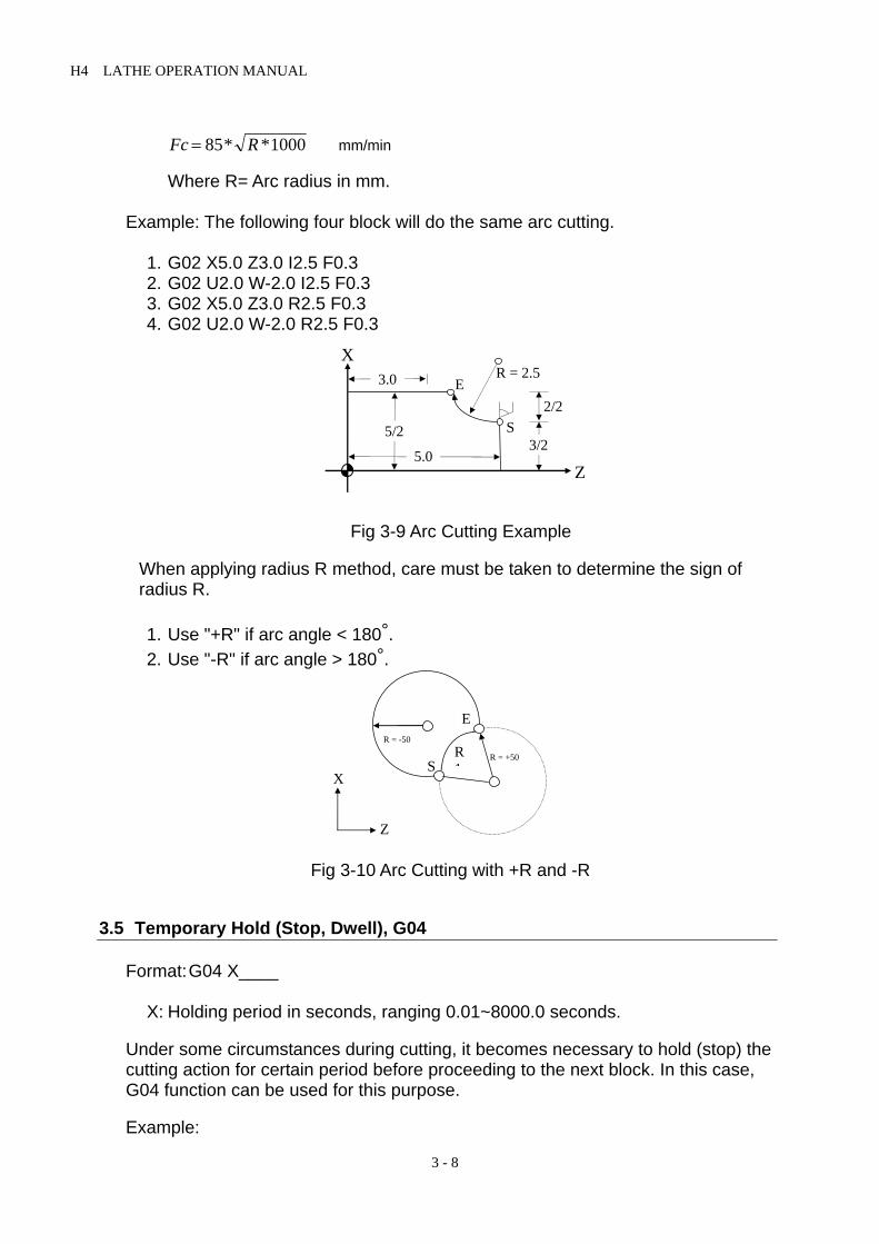
Fc R= 85 1000* * mm/min Where R= Arc radius in mm. Example: The following four block will do the same arc cutting.
1. G02 X5.0 Z3.0 I2.5 F0.3 2. G02 U2.0 W-2.0 I2.5 F0.3 3. G02 X5.0 Z3.0 R2.5 F0.3 4. G02 U2.0 W-2.0 R2.5 F0.3
Fig 3-9 Arc Cutting Example
When applying radius R method, care must be taken to determine the sign of radius R.
1. Use "+R" if arc angle < 180°. 2. Use "-R" if arc angle > 180°.
Fig 3-10 Arc Cutting with +R and -R
3.5 Temporary Hold (Stop, Dwell), G04
Format: G04 X____ X: Holding period in seconds, ranging 0.01~8000.0 seconds. Under some circumstances during cutting, it becomes necessary to hold (stop) the cutting action for certain period before proceeding to the next block. In this case, G04 function can be used for this purpose. Example:
3.0X
E
S
Z
R = 2.5
5.0
5/23/2
2/2
R = -50
S
E
R1
R = +50
X
Z

H4 LATHE OPERATION MANUAL
3 - 9
N1 G01 X10.000 Z10.000 F0.1 N2 G04 X2.000 ..... Hold for 2 seconds, then process to next block N3 G00 X0.000 Z0.000
3.6 Clear Machine Coordinates, G08 Format: G08 ..... Clear machine coord. in all axes or G08 X____Z____ ..... Clear machine coord. in X and Z-axis or G08 X____ ..... Clear machine coord. in X-axis or G08 Z____ ..... Clear machine coord. in Z-axis The number associated with X or Z does not have any meaning, but you have to have a number to input X and Z into the CNC buffer. When G08 is used in the program, the machine coordinates accumulated up to the G08 command for the specified axis (axes) will be cleared regardless of what numbers are with X and Z-axis.
3.7 Move To The First Reference Point, G28 Format: G28 ..... Move to the 1st ref. point in all axes or G28 X____Z____ ..... Move to the 1st ref. point in X and Z-axis or G28 X____ ..... Move to the 1st ref. point in X-axis or G28 Z____ ..... Move to the 1st ref. point in Z-axis The coordinate of the first reference point is set in the MCM parameter #40. The number associated with X or Z does not have any meaning, but you have to have a number to input X and Z into the CNC buffer. When encountering this command during cutting, the tool will move to the first reference point as set in MCM parameter #40 for the axis specified in the G28 block, regardless of what numbers are with X and Z-axis. The coordinates of MCM parameter #52 are determined by users, based on the machine origin being at (X=0, Z=0). This reference point is normally selected at some convenient location during machining. Therefore, if X=0, Z=0 are selected for MCM #52-MCM#54, G28 command will cause the tool moving to machine origin Note that prior to the G28 command, the tool offset compensation must be canceled and the tool offset compensation cancel command should not be used in the same block as the G28 command. Example: T100 ..... Tool offset compensation canceled G28 X10. ..... Tool moves to the first reference point in X-axis.

H4 LATHE OPERATION MANUAL
3 - 10
3.8 Return To The Previous Location From The Reference Point, G29 Format: G29 ..... Return from the ref. point in all axes or G29 X____Z____ ..... Return from the ref. point in X and Z-axis or G29 X____ ..... Return from the ref. point in X-axis or G29 Z____ ..... Return from the ref. point in Z-axis The G28 command moves the tool to the first reference point. G29 command works just the opposite. It moves the tool from the reference point to the target point, either the last position prior to G28 command or the point indicated by X and Z in the program block. G29 command cannot be used alone instead it is used immediately following a G28 or G30 command. Again, the number associated with X or Z does not have any meaning, but you have to have a number to input X and Z into the CNC buffer. Example: (only G29 in the block) G01 X60.00 Z30.00 ..... Tool at the location of X60., Z30. G28 ..... Tool moved from (X60, Z30) to the first reference point. G29 ..... Tool returns from the reference point to (X60, Z30)
3.9 Move To The Second (2nd) Reference Point, G30 Format: G30 .....Move to the 2nd ref. point in all axes or G30 X____Z____ ..... Move to the 2nd ref. point in X and Z-axis or G30 X____ ..... Move to the 2nd ref. point in X-axis or G30 Z____ ..... Move to the 2nd ref. point in Z-axis The method of application for this command is the same as for G28. The coordinates of this reference point are set in the MCM parameter #55-MCM#57.
3.10 Skip Function, G31 Format: G31 X (U)____Z(W)____ For Skip function G31 to be effective, it must be used in combination with an input signal to be received during the execution of G31 block. Once an input signal is detected, the tool will forgo the unfinished operation of current block and starts executing the next block. If no input signal is received during the execution of G31 block, the tool will move to the coordinates as specified with the cutting speed as G01. When G31 is doing linear cutting, the feed-rate will be the one in effect (G00 or G01). G31 is a one-shot G-code. Example: N10 G1 X10. Z10. ..........
H4 LATHE OPERATION MANUAL
3 - 11
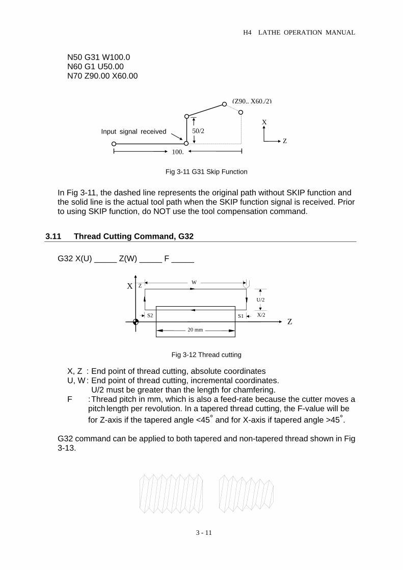
N50 G31 W100.0 N60 G1 U50.00 N70 Z90.00 X60.00
Fig 3-11 G31 Skip Function In Fig 3-11, the dashed line represents the original path without SKIP function and the solid line is the actual tool path when the SKIP function signal is received. Prior to using SKIP function, do NOT use the tool compensation command.
3.11 Thread Cutting Command, G32 G32 X(U) _____ Z(W) _____ F _____
Fig 3-12 Thread cutting X, Z : End point of thread cutting, absolute coordinates U, W : End point of thread cutting, incremental coordinates. U/2 must be greater than the length for chamfering.
F : Thread pitch in mm, which is also a feed-rate because the cutter moves a pitch length per revolution. In a tapered thread cutting, the F-value will be for Z-axis if the tapered angle <45° and for X-axis if tapered angle >45°.
G32 command can be applied to both tapered and non-tapered thread shown in Fig 3-13.
Input signal received
(Z90., X60./2)
100.
X
Z 50/2
X
Z 20 mm
S2 S1
U/2
X/2
WZ

H4 LATHE OPERATION MANUAL
3 - 12
Fig 3-13 Tapered and Non-tapered thread When doing thread cutting from rough to fine cut, Lathe controller will follow the same cutting path. This is accomplished by a position grid signal in the Z-axis installed on the spindle. The motion in the Z-axis will start when this signal is received. Due to the spindle acceleration and deceleration, imperfect thread will result on both ends shown as S1 and S2 in Fig 3-12. To avoid this, the length of cut thread should be little longer than the finished length. S1 and S2 can be estimated using the formula below. After finishing cutting of S2, the tool will retract at a beveled angle of 45° (Chamfer), based on the R-value and the thread pitch (F-value).
S S F S T1 2 0 51000 60
= =. * * *
*
S1, S2 : Imperfect thread length, mm S : Spindle speed, rpm F : Thread pitch, mm/rev T : G01 Acceleration and deceleration time, ms Example 1: Non-tapered thread with a specification of Thread pitch = 2 mm S1/S2 = 3 mm Thread depth = 1.4 mm (in diameter) with 2 cuts
Fig 3-14 Non-tapered Thread Cutting
N10 G0 X30.0 Z50.0 N20 M03 S2000 N30 G0 U-17.0 (Position for first cut = 1.0/2) N40 G32 W-26.0 F2.0 N50 G0 U17.0 N60 W26.0 N70 G0 U-17.4 (Position for second cut = 0.4/2) N80 G32 W-26.0 F2.0 N90 G0 U17.4 N100 W26.0 N110 M05 N120 M02
X
Z 20 mm
3 3
17/2 mm
15 mm

H4 LATHE OPERATION MANUAL
3 - 13
G32 X(U) _____ Z(W) _____ F _____R X, Z : End point of thread cutting, absolute coordinates
U,W : End point of thread cutting, incremental coordinates. U/2 must be greater than the length for chamfering. F : Thread pitch in mm. R : The setting value is the screw 1/2(big and small gap).
Fig 3-15(Example 2) 1/2(24-33)= -4.5 Example 2: Tapered thread with a specification of Thread pitch = 2 mm, and S1/S2 = 2 mm Thread depth = 1.4 mm (in diameter) with 2 cuts
Fig 3-15 Tapered Thread Cutting
N10 G0 X60.0 Z100.0 N20 M03 S2000 N30 G0 X23.0 Z72.0 (Position for first cut = 1.0/2) N40 G32 X32.0 Z28.0 F2.0R-4.5 N50 G0 X40.0 N60 Z72.0 N70 G0 X22.6 (Position for second = 0.4/2) N80 G32 X31.6 Z28.0 F2.0R-4.5 N90 G0 X40.0 N100 Z72.0 N110 M05 N120 M02
3.12 Tape Cutting Canned Cycle G33
Format:
G33 Z (W)______F______ Z (W) : The end of coordinate or the length F : Thread pitch G33 the execution progression of Z axis tape cutting canned cycle 1. Z axis tape cutting 2. Spindle off
X
Z 40 332
2 24
30 40

H4 LATHE OPERATION MANUAL
3 - 14
3. Wait for a complete stop of spindle 4. Spindle reverse (opposite direction to the previous round) 5. Z axis cut retreat 6. Spindle stop Example: A single thread Pitch is 1mm N10 M3 S800 N20 G33 Z100. F1.0 N30… Note 1:Before tape cutting, you should confirm the turning direction of spindle base
on the cutting. After approaching to the end, the spindle will stop. If you want to carry on the task, you need to restart the spindle.
Note 2:Because of its rigid taping, there is a certain decelerating time after the
spindle stop the signals. During its deceleration the Z -axis will still follow the turning of the spindle until it’s complete stop. Therefore, the actual depth of the pitch is deeper than it’s required.
Note 3:The rest of the notes are the same as G32 % 00933
G65 L90 P1 A#13100 B26 G65 L01 P#9001 A#13123 G65 L80 P2
N1 G65 L03 P#9001 A#13126 B#12223 N2 G32 W#9001 F#13106
M05 G04 X1.00
G65 L81 P3 A#9002 B3 M04 G32 W-#9001 F#13106 G65 L80 P4
N3 M03 G32 W-#9001 F#13106
N4 G04 X0.500 M05 M99
%
3.13 Canned Cycle Functions Lathe provides several canned cycle functions to simplify program design. These functions are divided into two groups: 1. Single canned cycle -- Do one cycle of cutting at a time. 2. Compound canned cycle -- Do more than one cycle of cutting, including
the finishing cut.
;BIT TEST #13100 BIT 26 ;#9001= “W’ ; ;#9001=#13126-#12223 ; ;Spindle Stop ;Dwell 0.5 second ;check if #9002=3, M03 ; ; ; ; ; ; ; ;

H4 LATHE OPERATION MANUAL
3 - 15
3.13.1 Single Canned Cycle, G90, G92, G94 G90, G92 and G94 command blocks must be followed by a G01 block to signal the completion of the canned cycle program. Otherwise, the canned cycle will be repeated again. • Outer/Inner Diameter Linear Canned Cycle --Lateral, G90 Format: G90 X(U)____Z(W)____F____ X, Z : Cutting end point C, absolute coordinate U, W : Cutting end point C, incremental coordinate F : Feed-rate for sections 2 and 3 (B~C~D)
Fig 3-16 G90 Linear Canned Cycle The moving speed for sections 1 and 4 are G00 rapid feed-rate. A is the starting point. Every time the CYCST button is pushed, the tool will go from A-B-C-D and returns to point A. Thus, G90 does one cycle of cutting. • Outer/Inner Diameter Tapered Canned Cycle --Lateral, G90 Format: G90 X(U)____Z(W)____R____F____ R : The difference between point B and C in radius. X, Z, U, W and F are identical to those for linear canned cycle.
Fig 3-17 G90 Tapered Canned Cycle
When using incremental coordinates, the signs (+/-) for U and W are determined by the tool's moving directions for sections 1 and 2 as shown in Fig 3-17. If it's heading toward positive coordinate, they are (+). Otherwise, they are (-).
A
X
Z BC
DZ
W
41
2
3 U/2
X/2
X
Z
Z W
A
B
C
D 41
2
3 U/2
X/2R

H4 LATHE OPERATION MANUAL
3 - 16
Fig 3-18 Sign Convention for U, W, R with G90 • Non-tapered Thread Canned Cycle, G92 Format: G92 X(U)____Z(W)____F____ All definitions for X, Z, U, W and F are the same as those for G32.
Fig 3-19 Non-tapered Thread Canned Cycle, G92
One G92 command block can replace four G32 program blocks. The imperfect thread calculation (S1 and S2) is the same as that for G32. The feed-rate will be G00 for sections 1 and 4. When pressing Feed-Hold during thread cutting, the tool will not stop until the end of section 3. • Tapered Thread Canned Cycle, G92 Format: G92 X(U)____Z(W)____R____F____ R : The difference between point B and C in radius. X, Z, U, W and F are identical to those for non-tapered thread canned cycle.
1. U-,W-,R- W
12
34
U/2
R
2. U+,W-,R+
W
1 2
34
U/2
R
3. U-,W-,R+
W
1
2 3 4
R
U/2
|R| < |U/2|
4. U+,W-,R-
W
1 2
3
4
R U/2
|R| < |U/2|
X
Z
A
X
ZBC
D Z W
41
2
3 U/2
X/2
F

H4 LATHE OPERATION MANUAL
3 - 17
Fig 3-20 Tapered Thread Canned Cycle, G92
When using G92 command, the tool will cut with a beveled angle of 45° (Chamfer) at point C. The length of chamfering is about one pitch length. Please refer to G76 function for more details. The length of section 3 should be greater than that for chamfering. • Linear Traversed Canned Cycle, G94 Format: G94 X(U)____Z(W)____F____ X, Z : Cutting end point C, absolute coordinate U, W : Cutting end point C, incremental coordinate with respect to point A F : Feed-rate for sections 2 and 3 (B~C~D)
Fig 3-21 Linear Traversed Canned Cycle, G94 G00 rapid feed-rate will be for sections 1 and 4 and the feed-rate for sections 2 and 3 is specified in the G94 block. • Tapered Traversed Canned Cycle, G94 Format: G94 X(U)____Z(W)____R____F____ R : The difference between point B and C. X, Z, U, W and F are identical to those for linear traversed canned cycle.
X
Z
Z W
A
B
C
D 41
2
3 U/2
X/2R
X
Z
Z W
B
C
A
D
1
2
3
4 U/2
X/2

H4 LATHE OPERATION MANUAL
3 - 18
Fig 3-22 Tapered Traversed Canned Cycle, G94 When using incremental coordinates, the signs (+/-) for U and W are determined by the tool's moving directions for sections 1 and 2 as shown in Fig 3-18. If it's heading toward positive coordinate, they are (+). Otherwise, they are (-).
Fig 3-23 Sign Convention for U, W, R with G94 Note that G90, G92, G94 are of modal codes and all the values for X(U), Z(W) and F will remain in effect unless they are re-defined. This is illustrated in the following example (G90 Canned cycle): Blocks N30~N50 are composed of three G90 canned cycles, then followed by G0 (N60) and G01 (N70) to terminate the canned cycle with finishing cut.
Fig 3-24 G90 Canned Cycle Example
1.U-,W-,R-
1
2 3
4 U/2
R W
2.U+,W-,R+
1
2
3
4 U/2
R W
3.U-,W-,R+
3
2 1
4 U/2
R
W
4.U+,W-,R-
3
2
1
4 U/2
R
W
X
Z
668/2
16/2 24/2 26/2
X
Z
X
Z
Z W
B
C
A
D
12
34 U/2
X/2R

H4 LATHE OPERATION MANUAL
3 - 19
N10 G0 X80.0 Z100.0 N20 M3 S2000 N30 G90 U-8.0 W-66.0 F2.0 N40 U-16.0 N50 U-24.0 N60 G0 U-26.0 N70 G1 W-66.0 F1.0 ..... Finishing cut with G01 N80 U2.0 N90 G0 X80.0 Z100.0 N100 M5 N110 M2
3.13.2 Compound Canned Cycle Functions, G70~G76 While single canned cycle functions are for relatively simple shape, compound canned cycle functions are for more complicate shape of the work-piece. The final cutting path for the work-piece is all that required for the compound canned cycle program design. Once the final cutting path is determined, Lathe will calculate and determine the path for the rough cut. These functions are also applicable to thread cutting. 1. Compound Canned Cycle, Lateral Rough Cut, G71 Format: G71 U(∆d) R(e)
G71 P(ns) Q(nf) U(∆u) W(∆w) F(f) S(s) T(t) T____ X____ Z_____ S____ N(ns) .......... .......... .......... N(nf) .......... G70 P(ns) Q(nf) ..... Final cut will be explained later.
Fig 3-25 Tool path for G71 Canned Cycle, Rough Cut
∆de
(G00)
(F)
A
C
A
B
∆w
∆U/2
G00-Rapid feed F - G01 Feed-rate
G70 Final cutting path
* When final cut changing tool, the T**** must write it before the N(ns). It can reuse this code but must be noted: the T**** value must be the same.
* Executing the T code first line, the X,Z mean: when changing tool, the tool goes back to the safety position, after that, the node of T code means; going back to the safe path (ns).
* It will not execute the T code when Rough Cutting.

H4 LATHE OPERATION MANUAL
3 - 20
In Fig 3-25: • The final cutting path is A~A1~B~A. • A~C is the tool retraction during the rough cut and is internally calculated using U(∆u) and
W(∆w). • The last cycle of the rough cut is parallel to the path of the final cut. • For the path A~A1, no movement in Z-axis is allowed. Either G00 or G1 feed-rate is allowed. • For the path A1~B, the coordinates for both X- and Z-axis should be of the type being gradually
increased or decreased. • The cutting depth U(∆d) and the tool retraction after each rough cut R(e) are modal codes. G71 can be applied to the four types of cutting paths as shown in Fig 3-25. The main cutting path during rough cut is parallel to the Z-axis. The sign (+/-) convention for U and W is also shown in the figure.
U(∆d) : Cutting depth, actual value (radius, positive). If not specified, the U-value of PARAMETERS「G71,G72 Cutting
depth」will be used. R(e) : Amount of tool retraction after each rough cut (radius value). If not specified, the E-value of PARAMETERS「G71,G72 Retraction」
will be used. P(ns) : The block number for the starting block of the final cut. Q(nf) : The block number for the last block of the final cut. U(∆u) : Amount of material to be removed for final cut, X-axis. W(∆w) : Amount of material to be removed for final cut, Z-axis. F(f) : The feed-rate for rough cut only. S(s) : The spindle speed for rough cut only. T(t) : The tool number for rough cut only. The F, S and T specified in the blocks N(ns)~N(nf) are for final cut G70
only and will NOT affect those specified in the G71 block. N(ns) : The block number for the starting block of the final cut. N(nf) : The block number for the last block of the final cut. The program for blocks N(ns)~N(nf) is the cutting path for the final finishing cut and the max. number of blocks for N(ns)~N(nf) is 50. Do NOT use sub-program call between N(ns)~N(nf).
Fig 3-26 Tool path for G71 Canned Cycle, Rough Cut
U+,W+B A
A
X
Z
U+,W-B A
A
U-W+B A
A
U-W-B A
A

H4 LATHE OPERATION MANUAL
3 - 21
Fig 3-27 Sign Convention for U, W with G71 Example with G71, G70: Fig 3-26 Example with G71, G70 Compound Canned Cycle N10 G00 X100.000 Z140.000
N20 M03 S1000
N30 G71 U7.000 R1.000
N40 G71 P80 Q140 U4.000 W2.000 F3.00
N50 T101 X100.000 Z140.000
N60 T101 X
N70 T101 Z
N80 G01 X25.0 F1.50
N90 W-10.000
N100 X50.000 W-20.000
N110 W-20.000
N120 X75.000 W-15.000
N130 W-15.000
N140 X100.000 W-15.000
N150 G70 P80 Q140
N160 M05 S0
N170 M02 2. Compound Canned Cycle, Traversed Rough Cut, G72 Format: G72 W(∆d) R(e)
G71 P(ns) Q(nf) U(∆u) W(∆w) F(f) S(s) T(t) T____ X____ Z_____ S____ N(ns) .......... .......... .......... N(nf) .......... G70 P(ns) Q(nf) ..... Final cut will be explained later.
* It will not execute the T code until final cutting.
* N60、N70 the T code must be written before the N80【P(ns)】and it can be reused.
* If there is some obstacle between 【changing tool safety point】to【starting point of the final cut】, you can use this way to arrive the starting point of the final cut.
255075100
F71,G70 start point(100/2,140)
45 15 15 15 20 20 10
X
Z 2
2
7 (cutting depth) 1 (tool retraction)
Amount for final cut
G70 final cut
Changing tool safety point
* When final cut changing tool, the T**** must write it before the N(ns). It can reuse this code but must be noted: the T**** value must be the same.
* Executing the T code first line, the X,Z mean: when changing tool, the tool goes back to the safety position, after that, the node of T code means; going back to the safe path (ns).
* It will not execute the T code when Rough Cutting.

H4 LATHE OPERATION MANUAL
3 - 22
Fig 3-28 Tool path for G72 Canned Cycle, Traversed Rough Cut Except for the cutting path, all the command codes in the program are the same as those for G71 canned cycle. The main cutting path for G72 is parallel to the X-axis. • The final cutting path is A~A1~B~A described by N(ns)~N(nf). No sub-program
call is allowed between N(ns)~N(nf). • A~C is the tool retraction during the rough cut and is internally calculated using
U(∆u) and W(∆w). • The last cycle of the rough cut is parallel to the path of the final cut. • For the path A~A1, no movement in X-axis is allowed. Either G00 or G1
feed-rate is allowed. • For the path A1~B, the coordinates for both X- and Z-axis should be of the type
being gradually increased or decreased. • The cutting depth U(∆d) and the tool retraction after each rough cut R(e) are
modal codes. G72 can be applied to the four types of cutting paths as shown in Fig 3-29. The sign (+/-) convention for U and W is also shown in the figure.
Fig 3-29 Sign Convention for U, W with G72
∆d
(G00)
(F)
ACA1
B
∆w
∆U/2 G00-rapid feed F - G01 feed-rate
G70 final cutting path e
X
Z
U-,W-
B
A A1
U+,W-
B
A A1
U+,W+
B
AA1
U-,W+
B
AA1

H4 LATHE OPERATION MANUAL
3 - 23
Example with G72, G70:
Fig 3-30 Example with G72, G70 Compound Canned Cycle N10 G00 X108.000 Z130.000
N20 M03 S2000
N30 G72 W10.000 R1.000
N40 G72 P80 Q130 U4.0 W2.0 F3.00
N50 T101 X108.000 130.000
N60 T101 X Z
N70 T101 X
N80 G00 Z45.000
N90 G01 X75.000 W15.000 F1.50
N100 W15.000
N110 X50.000 W15.000
N120 W20.000
N130 X25.000 W20.000
N140 G70 P80 Q130
N150 M05 S0
N160 M02
3. Compound Contour Canned Cycle, Rough cut, G73 The G73 function is particularly useful for cast work-piece. Format: G73 U(∆i) U(∆k) R(d)
G73 P(ns) Q(nf) U(∆u) W(∆w) F(f) S(s) T(t) T____ X____ Z_____ S____ N(ns) .......... .......... .......... N(nf) .......... G70 P(ns) Q(nf) ..... Final cut will be explained later.
U(∆i) : Cutting depth in X-axis, actual value (radius, positive).
If not specified, the U-value of PARAMETERS「G73 Total cutting depth –X axis」will be used.
255075100
45 15 15 15 20 20
X
Z 2
2
Amount of final cut
G70 final cutting path
10 (cutting depth)1 (tool retraction)
(108/2,130) G71,G70 start point
Changing tool safety point
* When final cut changing tool, the T**** must write it before the N(ns). It can reuse this code but must be noted: the T**** value must be the same.
* Executing the T code first line, the X,Z mean: when changing tool, the tool goes back to the safety position, after that, the node of T code means; going back to the safe path (ns).
* It will not execute the T code when Rough Cutting.
* It will not execute the T code until final cutting.
* N60、N70 the T code must be written before the N80【P(ns)】and it can be reused.
* If there is some obstacle between 【changing tool safety point】to【starting point of the final cut】, you can use this way to arrive the starting point of the final cut.

H4 LATHE OPERATION MANUAL
3 - 24
W(∆k) : Cutting depth in Z-axis, actual value (radius, positive). If not specified, the W-value of PARAMETERS「G73 Total cutting
depth –Z axis」will be used. R(d) : Number of rough cut before final cut. If not specified, the D-value of PARAMETERS「G73 cutting cycle」will
be used. P(ns) : The block number for the starting block of the final cut. Q(nf) : The block number for the last block of the final cut. U(∆u) : Amount of material to be removed for final cut, X-axis. W(∆w) : Amount of material to be removed for final cut, Z-axis. F(f) : The feed-rate for rough cut only. S(s) : The spindle speed for rough cut only. T(t) : The tool number for rough cut only. The F, S and T specified in the blocks N(ns)~N(nf) are for final cut G70
only and will NOT affect those specified in the G73 block. N(ns) : The block number for the starting block of the final cut. N(nf) : The block number for the last block of the final cut.
The program for blocks N(ns)~N(nf) is the cutting path for the final finishing cut and the max. number of blocks for N(ns)~N(nf) is 50. Do NOT use sub-program call between N(ns)~N(nf).
Fig 3-31 Tool path for G73 Canned Cycle, Rough Cut In Fig 3-31: • The final cutting path is A~A1~B~A, described by N(ns)~N(nf). • A~C is the tool retraction during the rough cut and is internally calculated using U(∆i), W(∆k),
U(∆u), and W(∆w). • For the path A1~B, the coordinates for both X- and Z-axis should be of the type being gradually
increased or decreased. • The cutting depth, U(∆i), W(∆k) and R(d) are modal codes.
B
A1
A
12
3
C∆ ∆k w+
∆ ∆i u+ /2
∆U/2
∆w
A~ C total tool retraction 1,2,3 rough cut sequence

H4 LATHE OPERATION MANUAL
3 - 25
Example with G73, G70 Function:
Fig 3-32 Example of Compound Canned Cycle for G73, G70
N20 G00 X120.000 Z150.000 N30 G73 U14.000 W14.000 R3
N40 G73 P80 Q100 U4.000 W2.000 F3.00
N50 T101 X120.000 X150.000
N60 X Z
N70 X
N80 G00 X25.000 W-20.000
N90 G01 X50.000 W-20.000 F1.5
N100 W-20.000
N110 X75.000 W-15.000
N120 W-15.000]
N130 G01 X100.000 W-15.000
N140 G70 P80 Q100
4. Final Finishing Cut Function, G70
The G70 is used to remove all the rough spots from G71, G72 and G73 canned cycle and produce a fine final product.
Format: G70 P(ns) Q(nf)
P(ns) : The block number for the starting block of the final cut. Q(nf) : The block number for the last block of the final cut.
The F, S and T-code specified within the final cut program is valid for final cut only and won't affect those for rough cut.
5. Compound Grooving Canned Cycle, Lateral, G74
Format:
255075 100
45 15 15 15 20 20 20
X
Z 2
2
Amount of final cut
G70 final cutting path
(120/2,150)
G71,G70start pointFirst cycle
4. 67=14/3 (cutting of final cut)
* It will not execute the T code until final cutting.* N60、N70 the T code must be written before
the N80【P(ns)】and it can be reused. * If there is some obstacle between 【changing
tool safety point】to【starting point of the final cut】, you can use this way to arrive the starting point of the final cut.

H4 LATHE OPERATION MANUAL
3 - 26
G74 Z(W)____k (∆k) R(e) F____
R(e) : Tool retraction in Z-axis after each cut ∆k. If not specified, the R-value of PARAMETERS「G74,G75 Retraction」
will be used. Z : Absolute coordinate in Z-axis at point C. W : Incremental coordinate in Z-axis from A to C. K(∆k) : Each cutting depth in Z-direction (integer in µm). F : Grooving feed-rate.
Fig 3-33 Compound Lateral Grooving Canned Cycle, G74
Tool retraction R(e) is a modal code. It will not change before another value is designated. When X axis is located in the center ( x=0), it can be used for part drillings. Example: G0 X0. Z80. →Tool cut positions to the part origin at X0. Z80. M03 S2000 →Spindle turns clockwise at the speed of 2000 (rpm). G74 Z30. K10.R3.F0.2 →Canned cycle:”Z30” represents drilling cycle ends at 30 of Z absolute
coordinate. K10 shows 10,000 (µm) each drilling amount. R3 means 3000 (µm) each amount of tool retraction.
M05 S0 →Spindle stops M02 →Program ends
Fig.3-34
Z
X
AD
C e Tool
k k
Z W
10 10
3A
30
TOOL
80
X
Z

H4 LATHE OPERATION MANUAL
3 - 27
6. Compound Grooving Canned Cycle, Traversed, G75 The G75 function is identical to G74 except that the grooving direction for G75 is parallel to X-axis.
Format: G75 X(U)____K(∆k) R(∆e) F____
R(e) : Tool retraction in X-axis after each cut ∆K. (diameter) If not specified, the R-value of PARAMETERS「G74,G75 Retraction」
will be used. X : Absolute coordinate in X-axis at point C. U : Incremental coordinate in X-axis from A to C. K(∆k) : Amount of tool movement in X-direction each cycle (integer in µm). F : Grooving feed-rate.
Fig 3-35 Compound Traversed Grooving Canned Cycle, G75
• The amount of tool retraction R(e) is a modal code. It will not change before
another value is designated. Example for grooving canned cycle: N10 G0 X80.0 Z50.0 N20 M03 S2000 N30 G75 X60. K5. R1. F0.5 N40 M5 S0 N50 M2 7. Compound Thread Canned Cycle, G76
Format: G76 P(m)(r)(a) Q(∆d min) R(d) G76 X(U)____Z(W)____R(i) P(k) Q(∆d) F(l) m : Number of fine cut. (2-digit, 01~99) If not specified, M-value of PARAMETERS「G76 Finish cutting cycle」
will be used. r : Length of chamfering. (2-digit) Length of chamfering = 0.1 * r * F(l)
Tool
Z
X D
k/2
U/2
X/2C
k/2
k/2
A

H4 LATHE OPERATION MANUAL
3 - 28
If not specified, R-value of PARAMETERS「Chamfer」will be used. a : Tool nose angle (2-digit). Enter as 0, 5, 10, 15 ..... 90°. If not specified, A-value of PARAMETERS「Tool-tip angle」will be
used.
Example: If m=2, r=12, a=60°, then the P-code command is P021260.
Q(∆d min): Minimum cutting depth for the last cycle. (integer µm) If the cutting depth for n-ht cycle, (∆ ∆d n d n -1− ) < (∆d min), then (∆d min) will be used for cutting. If not specified, Q-value of PARAMETERS「Min. cutting depth」will be
used. R(d) : Depth of final fine cut. If not specified, R-value of PARAMETERS「Depth for finish cut」will be
used. X, Z : Absolute coordinate of the end point ( D) for thread cutting. U, W : Incremental coordinate of the end point ( D) for thread cutting. R(i) : Radius difference on both end for tapered thread. If i=0, it's a non-tapered thread cutting. P(k) : Depth of thread. (radius, integer in µm) Q(∆d) : Cutting depth of the 1st cycle. (radius, integer in µm) F(l) : Thread pitch, (Same as feed-rate/revolution, see G32)
Fig 3-36 Compound Thread Canned Cycle, G76
• The length of segment DE (U/2) should be greater than the length of chamfering. • The command codes, P(m)(r)(a), Q(∆d min), and R(d) are all modal codes. • The segment CD is cut with feed-rate F(l) while the rest with G00. The sign for
incremental coordinate (U, W) and R is determined by the direction of segment AC and CD. In Fig 3-36, they are all negative.
• All the conditions and restrictions that apply to G32 and G92 functions are also applicable to G76.
The thread cutting sequence from start to finish is illustrated in detail as in Fig 3-37. Note that the material is removed from one side of the tool except the first cut and the cutting depth is gradually decreased. The first cutting depth is ∆d, the
C
X
Z
E A
D B
U/2
X/2 Z
i r
(G00) (G00)
(F)(G00)
W
d K
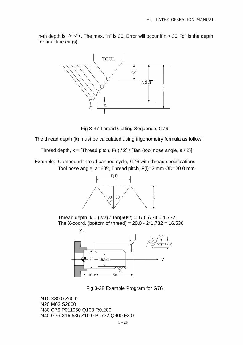
H4 LATHE OPERATION MANUAL
3 - 29
n-th depth is ∆d n . The max. "n" is 30. Error will occur if n > 30. "d" is the depth for final fine cut(s).
Fig 3-37 Thread Cutting Sequence, G76 The thread depth (k) must be calculated using trigonometry formula as follow: Thread depth, k = [Thread pitch, F(l) / 2] / [Tan (tool nose angle, a / 2)] Example: Compound thread canned cycle, G76 with thread specifications: Tool nose angle, a=60o, Thread pitch, F(l)=2 mm OD=20.0 mm.
Thread depth, k = (2/2) / Tan(60/2) = 1/0.5774 = 1.732 The X-coord. (bottom of thread) = 20.0 - 2*1.732 = 16.536
Fig 3-38 Example Program for G76
N10 X30.0 Z60.0 N20 M03 S2000 N30 G76 P011060 Q100 R0.200 N40 G76 X16.536 Z10.0 P1732 Q900 F2.0
TOOL
d
d nk
d
k
F(1)
30 30
X
Z20 16.536
10 502
0.9
1.732

H4 LATHE OPERATION MANUAL
3 - 30
N50 M05 N60 M02
8. Notes on Compound Canned Cycle (G70~G76) • All the numbers that re associated with the command codes must be accurate. • G70, G71, G72, and G73 are not valid in MDI mode. • For G71, G72, and G73 functions, the program is subject to the following
restrictions. 1. The program block specified by P(ns) must have a G00 or G01. Otherwise, an
error message will be displayed. 2. The program blocks specified by P(ns)~Q(nf) can NOT execute T-code, M98
sub-program call and M99 sub-program finish. 3. The program block numbers for P(ns)~Q(nf) should NOT be repeated. 4. The last program block specified by P(ns)~Q(nf) should not be the one
containing tool retraction. • During compound canned cycle execution, the cutting operation can be stopped
by "Feed Hold" and do some manual operation. However, before the cutting operation is resumed, the cutting tool must be returned to the location where the tool was stopped. Otherwise, the restart location will be drifted by an amount equal to the distance during manual operation.
3.14 Max. Spindle Speed Setting, G50
Format: G50 S____ S : Max. spindle speed, rpm (revolutions/min) G50 command is normally used with G96 function, constant surface cutting speed.
3.15 Constant Surface Cutting Speed Setting, G96 Format: G96 S____ S : Constant surface cutting speed, mm/min Surface cutting speed is referred as the tangential velocity of the contact point between the cutting tool and the work-piece with the cutting plane parallel to the X-axis. When the surface cutting speed is maintained at a constant, the spindle rpm is gradually increasing as the diameter of the work-piece is getting smaller. When the spindle rpm reaches the ax setting by G50, the constant rpm takes over. The relationship between surface cutting speed, work-piece diameter and the spindle rpm is expressed by: V D N= π* * V : Constant surface cutting speed, mm/min D : Diameter at the cutting point, mm N : Spindle rpm, rev/min

H4 LATHE OPERATION MANUAL
3 - 31
Example: N10 G50 S2000 ....... max. rpm = 2000 N20 G96 S200 ....... constant surface cutting speed @ 200 mm/min
3.16 Constant RPM Setting (Constant Surface Cutting Speed Cancel), G97 Format: G97 S____ This command is used to set the cutting speed at a constant RPM of the spindle and cancel the G96 function at the same time.
3.17 Cutting Feed-rate Setting, G98, G99 Format: G98 --- Feed-rate per minute, mm/min G99 --- Feed-rate per revolution, mm/rev Lathe provides two types of feed-rate, mm/min and mm/rev. G99 is the power-on default setting. The relationship of these two settings is as follow: Fm Fr S= * Fm : Feed-rate per minute, mm/min Fr : Feed-rate per revolution, mm/rev S : Spindle rpm, rev/min
3.18 English/Metric Measuring System Conversion, G20, G21 Format: G20 -- System measuring unit in INCH mode G21 -- System measuring unit in METRIC mode. This is the power-on
and RESET default.
3.19 Auxiliary Functions, M-codes, S-codes Lathe controller provides M-code functions for users to program certain mechanical actions outside the CNC controller. M-code function consists of a capital letter M followed by a 2-digit number, 00~99. Different M-code represents different action. The following M-codes are the ones used by Lathe system and customers should not attempt to change them. M00 Program stop. When the program execution comes to this point, all actions stop,
including spindle and the coolant. Press "CYCST" to re-start from where the program was stopped.
M01 Option stop. The program will stop only when the C-bit, C026=1. Please refer to
Section 5 of Chap 8 for details. M02 Program end. M30 Program end. M02 and M30 are identical. M98 Sub-program call. M99 Sub-program end.

H4 LATHE OPERATION MANUAL
3 - 32
Except those mentioned above, the rest of the M-codes can be defined by users. The following M-codes come with the standard Lathe PLC, but users can redefine these M-codes if desired. M03 Spindle rotation in normal direction. M04 Spindle rotation in reversed direction. M05 Spindle rotation stops. M08 Coolant ON. M09 Coolant OFF. M10 Spindle chuck unclamp M11 Spindle chuck clamp M15 Counter +1 M16 Counter clear The S-code is used to limit the maximum rpm of the spindle rotation. The max. setting is S999999. Example: S1000 ..... The max. spindle rpm is 1000 rev/min
3.20 Sub-program When a group of program steps will be used repeatedly, these program steps can be grouped in a sub-program that can be called out for execution whenever is required from the main program. In doing this way, the structure of the program can be greatly simplified. The structure of the sub-program is pretty much the same as the main program except that the sub-program is ended with a M99 as follows: O005 Program number (No 5 in this case) ........... Program step ........... Program step M99 Program end The sub-program can be independently executed by pressing the "Auto" and "CYCST" button. However, the execution will go round and round to a max. of 8000 times because the sub-program is ended with a M99 function. Execution of a sub-program from a main program Format: M98 P____L____ P : Sub-program number L : Number of execution. If not specified, execute once. Example: M98 P05 ....... Execute sub-program No 5 once. M98 P05 L3 ....... Execute sub-program No 5 three times. The M98 block can not contain any position code, such as X or Z except those shown in the format. A sub-program can call another sub-program. This stepwise sub-program call can go up to a max. of 5-level for Lathe controller as below:

H4 LATHE OPERATION MANUAL
3 - 33
Fig 3-39 Sub-program Call
3.21 Total Offset Compensation Set and Cancel Total offset compensation = Offset compensation + Wear compensation Format:
Compensation Set Compensation Cancel Without Turret Tyy T00
With Turret Txxyy Txx00 yy : Group number or the compensation data xx : Tool number 00 : "T" followed by zero means compensation cancellation When the compensation group number is specified, the controller will add the appropriate numbers (offset and wear data) together from【Tool offset compensation】and【Tool wear compensation】, then make a total compensation to the cutting operation. Note that the tool wear compensation can be used to make minor offset adjustment due to a small difference in the tool length. Therefore, if the machining produces a little smaller work-piece, a (+) wear can be added to compensate for that minor difference. If it's a little too big, use (-) wear. Please note: 1. When power-on, default to compensation cancel with group number "00 or 0". 2. Cancel compensation function before execute "Auto-CYCST". 3. The compensation command code "T" can occupy one program block. In this
case, the controller will compute the compensation internally and no tool movement will occur in this block.
Example: N10 G01 X50.0 Z100.0 T0202 ..... Compensation start with T0202 N20 Z200.0 N30 X100.0 Z250.0 T0200 ..... Compensation cancel with T0200
N1 ... . . N5M98P2 . . N31 M2
N1 ... . . N5M98P4 . . N32 M99
N1 ... . . N5M98P3 . . N32 M99
N1 ... . . N5M98P5 . . N32 M99
N1 ... . . . . . N32 M99
PROGRAM 1 PROGRAM 2 PROGRAM 3 PROGRAM 4 PROGRAM 5

H4 LATHE OPERATION MANUAL
3 - 34
Fig 3-40 Example for Tool Offset Compensation Tool-tip Radius Compensation The tool-tip (or tool-nose) is always made in a circular shape as in Fig 3-41. When making a straight line cut along the X- or Z-axis, the resulting cut will be accurate because the contact point of the tool-tip with the work-piece is at A and B.
Fig 3-41 Circular Shape of A Tool-tip When making a circular cut or a oblique line cut (movement in both X- and Z-axis), however, the contact point will be somewhere between A and B instead of the program reference point P, which is the intersect for the two tangential lines drawn from point A and B. Point P is an imaginary tool-tip and, in reality, it does not exist. It is usually used for programming. Without tool-tip radius compensation, the resulting cut will produce an error shown as shaded area in Figs 3-42 and 3-43. To correct this problem, tool-tip radius compensation function can be used.
Fig 3-42 Error in A Oblique-line Cut Without Radius Compensation
Path of program reference point after compensation Compensation cancel
Compensation start
N10 N20
N30
Path of program reference point before compensation
Cr
A
B
P
(OD cutter)
Cr
A
B
P
(ID cutter)
X
Z
A
B P
D
C
P2
P1 Un-cut portion

H4 LATHE OPERATION MANUAL
3 - 35
Fig 3-43 Error in A Circular Cut Without Radius Compensation
The Tool-tip Radius and The Direction When applying tool-tip radius compensation, two data must be known: Tool-tip radius : Store under column "R" of 【Tool offset compensation】, in mm. Tool-tip direction : Store under column "T" of 【Tool offset compensation】, 0~9. Tool-tip radius is normally provided by the tool manufacturer, while the tool-tip direction is normally expressed in an integer from 0 to 9 as shown in Fig 3-44. For a turning machine with tool at the rear, tool-tip direction 3 is for OD (outside diameter) cutting and direction 2 for ID (inside diameter) cutting. The range of tool-tip radius compensation is 0 ~ +/- 999.999 mm.
Fig. 3-44 Direction of The Tool-tip
Direction-1 Direction-2
Direction-3 Direction-4
Direction-5 Direction-6
Direction-7 Direction-8
Direction-0,9
2 1 6
7 0 9 5
83 4
Simplified as follow
X
Z
Path for imaginary tool-tip Un-cut portion P2
P1
0

H4 LATHE OPERATION MANUAL
3 - 36
3.22 Tool-tip Radius Compensation Command, G40,G41,G42 Format: Tyy or Txxyy ..... Call tool or group number G41 (or G42) X(U)____ Z(W)____ ..... Compensation function set G40 ..... Compensation cancel The tool number or group number must be declared before setting compensation function in effect. The direction of compensation is specified by the command codes, G41 or G42. G41 causes the tool to compensate (move) to the left of the program path and G42 does to the right. The direction of compensation (right or left of the tool path) is shown in Fig 3-45. Use G41 if the compensation tool path falls to the left of the program path and use G42 if falls to the right. Since the arrow can point to any direction, be careful about the compensation direction when applying.
Fig 3-45 Application for G41 and G42 Start of Tool-tip Radius Compensation: When executing a program block with G41 or G42 command, the tool will move with a G01 speed to the location specified by X, Y. When the tool reaches X, Y, the tool-tip will be offset by an amount equal to the tool radius. From this point on, the tool radius compensation is in effect. Therefore, the tool-tip radius compensation must be started in a block with G00 or G01 linear motion. An error will result if user attempts to start radius compensation in a block with G02/G03 command. Followings are some examples to start tool-tip radius compensation. (The direction of the tool-tip is 0/9) Example 1:
N1 G01 X____Z____F____T____ N2 G41 (G42) X____Z____ N3 Z____
B
G42
G41
N2N3
A
Program path
G42 (compensation to right)
XX
ZDirection of tool path
G41 (compensation to right)
Work-price

H4 LATHE OPERATION MANUAL
3 - 37
Fig. 3-46 Start of Tool-tip Radius Compensation - 1
Example 2:
N1 G01 X____Z____F____T____ N2 G41 (G42) X____Z____ N3 X____Z____I____K____
Fig. 3-47 Start of Tool-tip Radius Compensation - 2 Cancel of Tool-tip Radius Compensation Once G41 or G42 has been set in effect, G40 command must be used to cancel the tool radius compensation. The cancellation of radius compensation has to be done in a linear motion environment, such as G00 or G01, but NOT in the block with G02/G03. G40, G41, and G42 are all modal G-codes. Followings are some examples illustrating the application of G40 command. Example 1:
N20 G41 (G42) ...... .......... .......... N31 G01 Z____F____ N32 G40 X____Y____
Fig 3-48 Cancel of Tool-tip Radius Compensation - 1
B
G4
G41
N2N3
A
Program path
A
G41
G42
N32 G40N31
B
Program path

H4 LATHE OPERATION MANUAL
3 - 38
Example 2 :
N10 G41 (G42) ....... .......... .......... N15 G02 X____Z____I____K____F____ N20 G01 N25 G40 X____Z____
Fig 3-49 Cancel of Tool-tip Radius Compensation - 2
Notes On Tool Radius Compensation 1. When the tool-tip radius compensation is in effect, the section of program to be
executed should not contain more than two consecutive program blocks that do not have motion command. Followings are commands that do not produce any cutting motion and cannot be used consecutively in two blocks when radius compensation is in effect.
M05 ..... M-code command S2100 ..... S-code command G4 X1.000 ..... Temporary stop G1 U0.000 ..... Coordinate increment=0. G98
2. The insertion (start) of the tool-tip radius compensation should be done in a
block with G00 or G01 command. 3. Do not execute tool-tip radius compensation in an MDI mode. 4. Do not execute tool-tip radius compensation under G74, G75, or G76 function. 5. When cutting around an inside corner, the arc radius of inside corner must be
equal to or greater than the tool-tip radius. Otherwise, an error will result. Cutting around an outside corner is, however, NOT subject to this type of restriction.
6. For a sharp corner as shown below, OD cutting will be OK. For ID cutting, operation will be normal (with some uncut portion) if the gap C is
greater than tool-tip radius. Otherwise, "Over-cutting alarm" will occur.
Program path AG41
G42 N25 G40N20
B

H4 LATHE OPERATION MANUAL
3 - 39
Fig 3-50 7. When machining a step-wise work-piece with step size smaller than the tool
radius, over-cutting will be produced as shown in Figure 3-51.
Fig 3-51 Over-cutting (Shaded area) Tool-tip Radius Compensation Example:
Tool number = 02, tool-tip direction = 3, tool-tip radius = 1.5 mm.
Fig 3-52 Example of Tool-tip Radius Compensation
A P
B
C
Program path
G42 G41
11 10 9
8 7
6 5 4
3
2 1
R=25
S start
Z
X

H4 LATHE OPERATION MANUAL
3 - 40
N10 G0 X100. Z120. ..... Point S N20 G0 X0. Z110. ..... Point 1 N30 M3 S2000 N40 G42 Z100. T02 F3.0 ..... Point 2, insertion of radius compensation N50 G1 X20. ..... Point 3 N60 X30. Z91.34 ..... Point 4 N70 Z75. ..... Point 5 N80 G02 X44.644 Z57.322 I25. F1.5 ..... Point 6, circular cutting N90 G01 X76. Z37.644 F3.0 ..... Point 7 N100 Z20. ..... Point 8 N110 X80. ..... Point 9 N120 Z0. ..... Point 10 N130 G40 X90. ..... Point 11, cancel of radius compensation N140 G0 X100. Z120. ..... Point S N150 M05 N160 M02
There will be an over-cutting alarm if trying to return to Point S from Point 10. This is because the angle 9-10-S is too small. Also, an over-cutting alarm will occur for section 8~9 if the tool-tip radius is greater than 2.00 mm.

4 MCM Parameters
4 - 1
4 MCM PARAMETERS
4.1 MCM Parameter
The setting allows users set the system value on the controller by the various types of machines and the requirements. The parameters can be described into two parts such as basic parameters and machine parameters.
4.1.1 Basic Parameters Press key and press Soft-key to enter, as follows:
Fig 4-1
Fig 4-2
4.1.2 Machine Parameters Machine parameter setting is a crucial step to the system and tool executions, so you must handle with care. After the system setting, press “reset” to restart it.
T.Radius T.Ofsset
MCM

4 MCM Parameters
4 - 2
You continuously press the second page of basic parameter where is the Soft-Key on the right margin, for 5 seconds. It will automatically skip to the machine parameter display as follows:
Fig4-3
Fig4-4
Fig4-5 Setting completion: to press 『RESET』 Key and return to the ordinary mode. Revising methods of parameters:

4 MCM Parameters
4 - 3
Move the cursor up and down to the desired parameter position for revision and enter a new value and press 『INPUT』 key.
4.2 Parameter Descriptions 1. Set the Jog speed value on X –axis (mm/min) 2. Set the Jog speed value on Z-axis (mm/min) Format= (Default value 1000) 3. Set X-axis as the denominator for the resolution. 4. Set X-axis as the numerator for the resolution. 5. Set Z-axis as the denominator for the resolution. 6. Set Z-axis as the numerator for the resolution. The setting is based on machine motion device (like ball screw) and servo motor pulse feedback. After confirmation, do not readjust it without any instructions.
Ball Screw Pitch Resolution= Motor Encoder × Rate Gear Ratio
Example: X-axis of the ball screw pitch = 5.000mm Motor Encoder = 2500 pulses, Resolution=4 Gear Ratio= 5:1(Servo Motor Rotations: 5; Ball Screw Rotations: 1) 5000 1 1 Resolution= 2500 × 4 5 = 10 X –axis resolution of the denominator = 10 X- axis resolution of the numerator = 1 7. X-axis rate of resolution 8. Z-axis rate of resolution Format= (Default value=4) Setting=1 → stands for “ Feedback Signal times 1” 2 → stands for “ Feedback Signal times 2” 4 → stands for “ Feedback Signal times 4”
You can only choose one from the three. Warning: Rate setting is very much related to the rigidness of the machine structure. When the structure passes the electric, the motor vibrates a little. It is probably

4 MCM Parameters
4 - 4
because the rigidness is too great for the machine structure to hold. You shall lower its axis rate for improvement.
Example: The feedback signal from the encoder is 2000 pulses. If the setting is 2 which means the feedback signal is 4000 (2000×2). 9. The highest feed-rate speed of X-axis. 10. The highest feed-rate speed of Z-axis. Format= (Default value =10000) Unit: mm/min Note: the setting is an integer format. If you set the Z-axis as 5000, which means that your highest feed rate will be 5000 msec per minute. The highest speed calculation is as follows: Fmax =0.95 ×the highest speed of servo motor rotations × axes pitch ÷ gear ratio. Example: The highest speed rotations of the servo motor on X-axis is 3,000 rpm, the ball screw pitch is 5mm and the gear ratio is 5:1(Servo motor rotations: 5; ball screw rotations:1) Fmax = 0.95 × 3000 × 5 ÷ 5 = 2850 Recommended setting is 2850 11. Motor rotating direction on X-axis. 12. Motor rotating direction on Z-axis. Format= (Default value = 0) If the setting is 0, the rotating direction is clockwise. If the setting is 1, the rotating direction is anticlockwise. The machine design is varied. Therefore, the servo motor can be installed on the ball screw toward four different directions. After installing, you can also utilize the parameter setting to revise the machine directions if the machine motion device heads to the opposite direction. Please note that the motor direction has nothing to do with the explanations below, but it is essential for connecting. Various designs for motion devices are different. Thus, it is likely that the controller doesn’t match the connection for encoder. It can cause the diversion (in high speed motor rotation) when the servo motor receives the error feedback signals. Before the directions of the servo motor has confirmed, the motor has to be separated from the machine. Wait till the direction has confirmed without any

4 MCM Parameters
4 - 5
mistakes reoccurred. Then, you can install it back on the machine. If the diversion still occurred, there is a way to re-correct it. You can try to switch the signal A and signal B and signal A- and signal B- of the connecting wires. 13. Set the speed 1 to return home on X-axis. 14. Set the speed 1 to return home on Z-axis. Format=(Default value=2500), unit: mm / min. 15. Set the speed 2 to return home on X-axis. 16. Set the speed 2 to return home on Z-axis. Format=(Default value=40), unit: mm / min. The users must note that the first speed moves to the limited switch on the machine when it returns home. The length of the limited switch must be larger than the decelerating distance. Otherwise, the machine will be beyond the limited switch and cause the wrong returned home. The examples and formulas for the length calculation on the limited switch: The length of the limited switch ≧ ( FDCOM ×ACC) ÷ 60,000 Note: 1. FDCOM = return home at the first speed 2. ACC = G01 acceleration and deceleration time 3. 60,000 msec (60 sec × 1000 = 60,000 msec) Example: FDCOM, returned the first speed = 3000 mm / min
ACC acceleration and deceleration time = 100 ms The shortest length of the limited switch=(3000× 100)÷60,000=5 mm
17. Set X-axis direction to return home. 18. Set Z-axis direction to return home. Format=(Default value =0) Set 0, the tool cut moves to the positive coordinate to return machine origin. Set 1, the tool cut moves to the negative coordinate to return machine origin. 19. Set X-axis software over travel limit in the positive direction. 20. Set Z-axis software over travel limit in the positive direction. Format=. (Default value=+9999.999), Unit / mm. Setting value is the positive distance from axis over travel limit to machine origin. 21. Set X-axis software over travel limit in the negative direction. 22. Set Z-axis software over travel limit in the negative direction. Format=. (Default value=+9999.999), Unit / mm.

4 MCM Parameters
4 - 6
Setting value is the negative distance from axis over travel limit to machine origin. The concept and description of over travel limit:
Fig.4-3 23. Set X-axis of backlash compensation. 24. Set Z-axis of backlash compensation. Format=. (Default value=0), Unit / mm. 25. Set the denominator of jog resolution on X-axis. 26. Set the numerator of jog resolution on X-axis. 27. Set the denominator of jog resolution on Z-axis. 28. Set the numerator of jog resolution on Z-axis. Format= (Default value=100), the explanation is as follows: Example: The denominator of the resolution = 100 The numerator of the resolution= 100 Jog rate R 222 =100 (PLC setting) Jog moves one block=100 pulses When the jog moves one block, the feed distance on the X-axis=100× (100÷100)=0.1mm =100µm Example: the denominator of resolution=200
The numerator of resolution=500 Jog rate R222=100 (PLC setting) Jog moves one block=100 pulses When the jog moves one block, The feed distance on Y axis=100×(500÷200)
EM-STOP Software Limit
5~10mm 5~10mm
EM-STOP
Machine origin
Software Limit

4 MCM Parameters
4 - 7
=0.250mm =250µm
29. Acceleration/deceleration type of setting Format=(Default value=0) Set the straight type=0. Set “S” curving type=1 30. Set G00 constant value of the accelerating / decelerating time. Format=(Default value=100),unit=1/1000 msec. Setting range is 4~512ms When the accelerating and decelerating form is 0, the G00 acceleration /deceleration will adopt the straight form. When the accelerating and decelerating form is 1, the G00 acceleration /deceleration will adopt the “S” curving form. It is still the same as the straight form. But the program operation will be double than the actual accelerating and decelerating time. 31. Set G99 constant of acceleration and deceleration. Format=(Default value=100),unit=1/1000 msec. Set the range is from 4 to 1024. Suggestion: G00 and G01 are 100 32. Set the accelerating and decelerating time of the spindle. Format=(Default value=100),unit=1/1000 msec. 33. Set the accelerating and decelerating time of the jog. Format=, (Default value=64),unit / msec. Setting range is from 4 to 512 ms. 34. Set the pulse numbers of spindle encoder. Format= (Default value = 4096) Setting value = the pulses of encoder × spindle encoder rate 35. Set the spindle encoder rate Format= (Default value=4) Set 1, stands for “feedback signal multiplies 1.” Set 2, Stands for “feedback signal multiplies 2.” Set 4, stands for “feedback signal multiplies 4.” These can only be chosen one at a time. 36. Set the motor speed of spindle when the output voltage is 10 V. Format= (Default value=3000), unit/ RPM

4 MCM Parameters
4 - 8
37. Set the spindle control method Format= (Default value=0) 38. Set the ratio for the horizontal axis. Format=. (Default value=256.000) 39. Set the location display for zero coordinate (horizontal axis) (1×8) Format= (Default value=1) 40. 40. Set the location display for zero coordinate (vertical axis) (22×8) Format= (Default value=22) 41. Set the location display (horizontal axis) (0×8) Format= (Default value=0) 42. Set the location display (vertical axis) (2×8) Format= (Default value=2) 43. Designated diameter or radius. Format= (Default value=0) Set 0, X-axis is radius programming. Set 1, X-axis is diameter programming. ※ < Time – 1~4> and <numbers of tool cut>
Please see the appendix at Chapter 7.
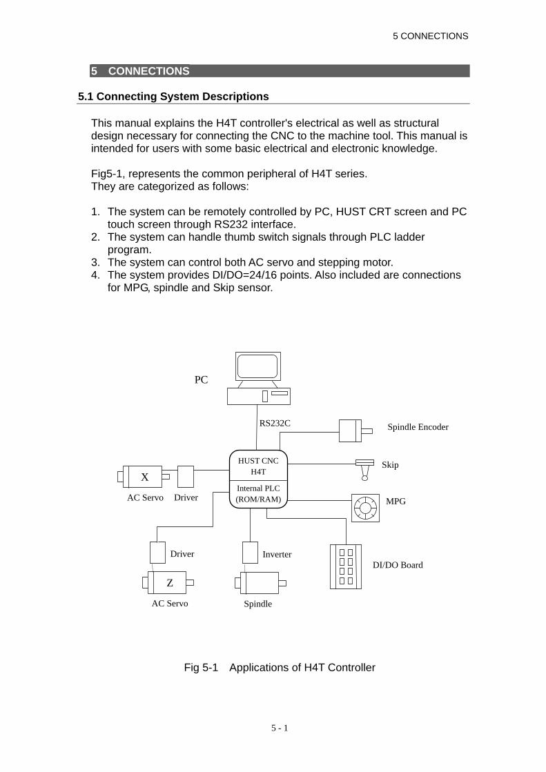
5 CONNECTIONS
5 - 1
5 CONNECTIONS 5.1 Connecting System Descriptions
This manual explains the H4T controller's electrical as well as structural design necessary for connecting the CNC to the machine tool. This manual is intended for users with some basic electrical and electronic knowledge. Fig5-1, represents the common peripheral of H4T series. They are categorized as follows: 1. The system can be remotely controlled by PC, HUST CRT screen and PC
touch screen through RS232 interface. 2. The system can handle thumb switch signals through PLC ladder
program. 3. The system can control both AC servo and stepping motor. 4. The system provides DI/DO=24/16 points. Also included are connections
for MPG, spindle and Skip sensor.
Fig 5-1 Applications of H4T Controller
PC
Spindle Encoder
Skip
Z
Driver
AC Servo
Inverter
Spindle
MPG
DI/DO Board
RS232C
HUST CNC H4T
Internal PLC(ROM/RAM)
X
Driver AC Servo

HUST CNC H4T MANUAL
5 - 2
5.2 System Installation 5.2.1 Ambient Surroundings H4-T series of CNC controllers must be installed and used in the following ambient surroundings. It can cause malfunctioning if the users utilize it outside any of these ambiences.
Ambient temperature must be between -0 to 45 during the operation and -20 to 55 in the storage and trafficking.
The maximum temperature change rate should be 1.1 per minute. Under the normal condition of humidity, the relative humidity should lower
than 80% RH and higher than 95% RH in a short time. The vibrant limitation should be at the maximum length of 0.075 mm with
the frequency of 5 hertz in operation. Noise: the maximum pulse should be 2000 V / 0.1 × 10⁻⁶ seconds per
0.01 second in operation. Consult us when installing the system in an environment with high degree
of dust, coolant, or organic solution. 5.2.2 Cabinet Considerations Pay attention to the following items when designing a cabinet. • The cabinet must be constructed to house the CNC unit, MDI panel and is
always a completely enclosed box. • Temperature rise within the cabinet should be 10o C or less than the
ambient temperature. • Sealing of the cable inlet/outlet or doors must be done thoroughly. • To avoid the noise interference, various units, the connecting cable and
the AC power source must be mounted at least 100 mm apart. In a magnetic field environment, this distance should be increased to at least 300 mm.
• When mounting the servo amplifier, please refer to the Servo Motor
Manual.

5 CONNECTIONS
5 - 3
5.2.3 Thermal Design in the Cabinet The cabinet for the control unit must be a closed structure, and the temperature rise within the cabinet must be 10o C or less than the ambient temperature. When designing a metal cabinet for a CNC unit, two factors must be considered, which are the heat source and the radiation area. For a CNC unit, the user cannot do too much to change the heat source. Therefore, the one thing that the user can do in controlling the temperature rise is the radiation area. The allowable temperature rise inside a metal cabinet can be estimated as follows: 1. With a cooling fan, the allowable temperature rise is 1o C/6 W/1 m2. 2. Without a cooling fan, the allowable temperature rise is 1o C/4 W/1 m2. This means that a cabinet with a radiation area of 1 m2 and a cooling fan will have an internal temperature rise of 1o C when a heating unit of 6 W (4W without a cooling) is inside the cabinet. The radiation area of a cabinet is the entire surface area of the cabinet minus the area contacting the floor. Example 1 (with a cooling fan): A cabinet has a 2 m2 radiation area with a temperature rise of 10o C. The maximum allowable heat value inside the cabinet is 6 W x 2 x 10 = 120 W. Therefore, the heat generated inside the cabinet must be kept less than 120 W. If the heat generated is 120 W or more in the cabinet, some other cooling devices, such as cooling fins, must be incorporated in the unit. Example 2 (without a cooling fan): A cabinet has a 2 m2 radiation area with a temperature rise of 10o C. The maximum allowable heat value inside the cabinet is 4 W x 2 x 10 = 80 W. Therefore, the heat generated inside the cabinet must be kept less than 80 W. If the heat generated is 80 W or more in the cabinet, some other cooling devices, such as fan, or cooling fins, must be incorporated in the unit.

HUST CNC H4T MANUAL
5 - 4
5.2.4 External Dimensions and Diagrams • H4T Keyboard Panel and LCD Screen
Fig 5-2 H4T Keyboard Panel and LCD Screen
H4T SIZE:267 ×362
F1 F2 F3 F4 F5
F
Y A
CYCST RESET I / O MCM
EDIT
PRNO
JOG
HOME
U A
WC
V B
R D
I O
K Q
M/
J P
T L
S E
N H
X Z
#
7 9 8
4 6 5
1 3 2
G
TAPE
TEACH
AUTO
MDI
INPUT
DEL.
0
CLEAR
NEWLINE
SP- CCW
SP- STOP
SP- CW
Lub.
COOLANT
SSO%
GO1
MFO%
GOO
MFO%TOOL
CHANGE
SERVO RELEASE
TOOLOFFSET
TOOLRADIUS
D1 D3D2
1 REF-POINT GRAPH
0.001
0.01
0.1
RAPID
X
Z Z
EM-STOP
ON
OFF
X

5 CONNECTIONS
5 - 5
• H4T CPU Main Board Connectors (Rear view)
Fig 5-3 H4-T CPU Main Board Connectors
INPUT OUTPUT SIO D/A X-AXIS Y-AXIS Z-AXIS SPINDLE MPG RS232
AC IN
AC OU
EMSTOP

HUST CNC H4T MANUAL
5 - 6
• Dimension for H4T Controller Box (Rearview)
Fig 5-4 Dimension for HUST H4T Controller Box (Rearview)
• Dimension for H4T Controller Box (Front View)
Fig 5-5 Dimension for HUST H4T Controller Box (Front View)
241
175.5 175.5
256
340
362
267
340
356
80 147.5 147.5 22.5

5 CONNECTIONS
5 - 7
• Cutout Dimension for H4T Controller Installation
Fig 5-6 Cutout for H4T controller Installation
175.5 175.5
Cutout:242 ×341
5
256
5
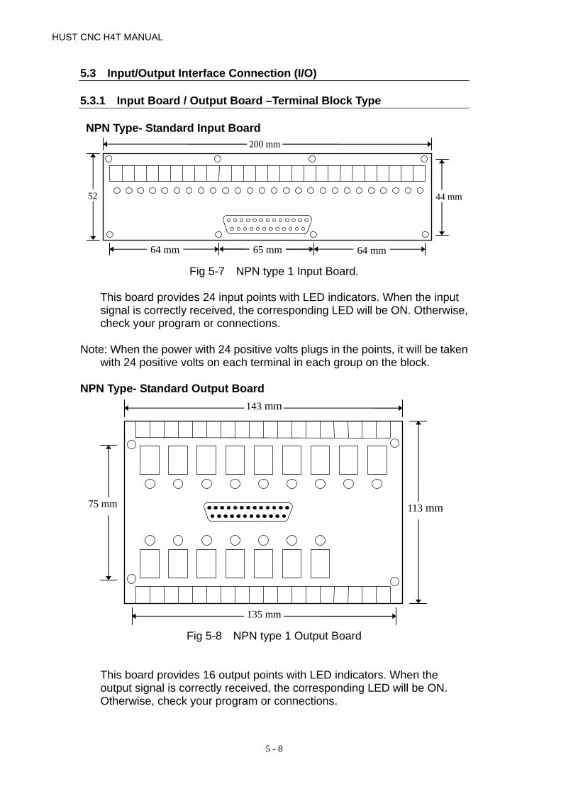
HUST CNC H4T MANUAL
5 - 8
5.3 Input/Output Interface Connection (I/O) 5.3.1 Input Board / Output Board –Terminal Block Type NPN Type- Standard Input Board
Fig 5-7 NPN type 1 Input Board.
This board provides 24 input points with LED indicators. When the input signal is correctly received, the corresponding LED will be ON. Otherwise, check your program or connections.
Note: When the power with 24 positive volts plugs in the points, it will be taken
with 24 positive volts on each terminal in each group on the block. NPN Type- Standard Output Board
Fig 5-8 NPN type 1 Output Board
This board provides 16 output points with LED indicators. When the output signal is correctly received, the corresponding LED will be ON. Otherwise, check your program or connections.
200 mm
52 44 mm
64 mm 65 mm 64 mm
113 mm 75 mm
143 mm
135 mm

5 CONNECTIONS
5 - 9
5.3.2 Input Board/Output Board- CE Rules Input Board
Standard NPN Input Board provides 24 input points with LED indicators. When the output signal is correctly received, the corresponding LED will be ON. Otherwise, check your program or connections.
Fig.5-9 Input Board
Note: When the power with 24 positive volts plugs in the points, it will be taken with 24 positive volts on each terminal in each group on the block.
+24V GND I07
+24V GND I06
+24V GND I05
+24V GND I04
+24V GND I03
+24V GND I02
+24V GND I01
+24V GND I00
+24VGNDI15
+24V GNDI14
+24V GNDI13
+24VGNDI12
+24V GNDI11
+24V GNDI10
+24VGNDI09
+24V GND I08
+24VGND I23
+24VGNDI22
+24V GNDI21
+24V GNDI20
+24V GNDI19
+24V GNDI18
+24V GNDI17
+24V GNDI16
+24V
GN
D +
24V
107 99
155
147
Unit:mm

HUST CNC H4T MANUAL
5 - 10
Output Board Standard NPN Output Board provides 16 output points. When it outputs, the signal indicator will be lighted. If DIP Switch is off, common connectors and normal-open are the ordinary switch connectors. If DIP Switch is on, common connectors can be directly connected with 24V signal ground. Therefore, when the magnetic valve, DC or motor from the normal-open block is driven by 24V signal ground, only to put DIP into on position. It is not necessary to connect common connectors with 24V signal ground.
Fig.5-10 Output Board
RELAY
NPNO_2S\N:AB147
O07O06O05O04O03O02O01O00
Switch
+24V
G
ND
+2
4V
OUTPUT DB25LM 155 mm
107 mm
+24V COM7 NO07
+24V COM6 NO06
+24V COM5 NO05
+24V COM4 NO04
+24V COM3 NO03
+24V COM2 NO02
+24V COM1 NO01
+24V COM1 NO01
DC +24V
RELAY+24V COM15
NO15
+24V COM14
NO14
+24V COM13
NO13
+24V COM12
NO12
+24V COM11 NO11
+24V COM10
NO10
+24V COM 9
NO09
+24V COM 8
NO08
O15O14O13O12O11O10O09O08
LED

5 CONNECTIONS
5 - 11
5.3.3 I/O Interface Connecting Assignment The pin assignment of 25-pin connector is shown in Fig 5-11. This assignment is standard in HUST controller and can be applied to those connectors on main board, input board, or output relay board. The connector designation on H4T controller is shown in Table 5-1. Note that the input connector has 24 I-points while output connector has 16 O-points.
Table 5-1 I/O Connector Designation and Pin Assignment
HUST CNC Connector Designation I/O Pin Assignment
P1 O 000 ~ O 015 H4T P2 I 000 ~ I 023
Fig 5-11 I/O Connector Pin Assignment (NPN-type) I/O signals can be connected directly to P1 and P2 connectors on H4T controller. All output points on H4T main board are transistor circuit with open collector. However, it would be advisable to use input board and output relay board before the signal going into the controller. This provides additional protection for main board on CNC from being damaged by electrical surge.
25
24
23
22
21
20
19
18
17
16
15
14
13
12
11
10
9
8
7
6
5
4
3
2
1
12
11
10
09
08
07
06
05
04
03
02
01
00
H4T P2, Input Pin Assignment (Female)
GND (24V)
23
22
21
20
19
18
17
16
15
14
13 GND (24V)
GND (24V)
+24V
+24V
00
01
02
03 04
05
06
07
08 09
10
11
12
13
14
15
H4T P1, Output Pin Assignment (Male)
25
24
23
22
21
20
19
1817
16
15
14
13
12
11
10
9
8
7
6
5
4
3
2
1

HUST CNC H4T MANUAL
5 - 12
5.3.4 Input Signals Input signal is the one from external devices to CNC controller, such as push button, sensor, limit switch, output relay board or proximity switch, etc. There are 24 inputs for H4T controller and their status can be displayed on LCD screen by pressing the blank key (below AUTO key) on the keyboard. • Input Signal Specification : The voltage to drive the input signal is 24V, but
the signal line is connected to the “sink” end (0V). The current is 8 mA. • Input Signal Directly Connected to CNC (NPN-type)
Input signal bypasses the input board and is directly connected to input connector on CNC.
Fig 5-12 Input Signal Directly Connected to CNC (NPN-type)
• Input Signal Connected to Input Board then to CNC (NPN-type) If input point is in use, the connector distribution is shown at the Fig 5-7, page 11.
Fig 5-13 Input Signal Connected to Input Board (NPN-type)
Signal Contact
R
External Tool
24V
DB25LF Input
R - 3.3K
CNC 5V GND
5V
0V
External
Signal Contact
Input Board
0
24VR
DB25LF Input
R - 3.3K
CNC 5V GND
5
24V
I-00

5 CONNECTIONS
5 - 13
5.3.5 Output Signals Output signal is the one from CNC controller to an external device. The output circuit of H4T controller is a transistor circuit that can be used to drive a relay or LED, etc. • Output Signal Specification:
a) With I/O relay board, each connection point on the board can withstand a maximum of AC 250V and 10A current.
b) Without I/O relay board, the output transistor circuit of H4T controller is rated at a maximum of 35V and 500 mA of current.
• Output Signal Directly Connected from CNC to Tool (NPN-type) If the output relay board is not used, the output signal can directly connects to the output points in CNC.
When output connector is directly connected to an inductive load, such as relay, it must connect a spark killer diode in parallel and as close to the load as possible. (See Fig 5-14) output terminal of H4T controller is open collector transistor circuit.
Fig 5-14 Output Signal from CNC without Relay Board (NPN-type) • Output Signal Connected to Output Relay Board (NPN-type) If output point is in use, the connector distribution is shown at the Fig 5-8 page 12.
Fig 5-15 Output Signal Connected to Relay Board (NPN-type)
RELAY
Ext. Device
Spark Killer
CNC Side
DB25LM Pin
DB25LM Output Output Board
Spark Killer
CNC Side 0V
24V
0 NO
Ext. Tool

HUST CNC H4T MANUAL
5 - 14
5.4 Connecting Diagrams
5.4.1 Connector Type
The types of connectors provided on the H3X/P-T controller box are summarized below. Each connector symbol is followed by a letter of either M (for male) or F (for female).
DB9LF (or M) : D sub type connector 9 pins female (or male). DB25LF (or M) : D sub type connector 25 pins female (or male). TBxx : Terminal block with pin number indicated by “xx”
5.4.2 Connector Designation The connector designation on H4T controller in printed on the back of the controller and their corresponding types are listed below.
Connector Name Connector Designation Type
Output Interface P1 DB25LM (Male)
Input Interface P2 DB25LF (Female)
D/A Spindle Analog Output P3 DB9LM (M)
X-axis Servo P4 DB9LF (F) Spindle P5 DB9LF (F) Z-axis Servo P6 DB9LF (F) MPG P7 DB9LM (M) I/O P8 DB9LF (F) RS232C Interface P9 DB9LF (F) Main Board DC Power JP1 TB6
Table 5-2 H4T Connector Designation and Type

5 CONNECTIONS
5 - 15
5.4.3 H4T Connection (Terminal Block)
H4T Main Connecting Diagram
Fig.5-16
INPUT 板
+24V GND
OUTPUT 板
+24V
0V
24V POWER-SUPPLY
SIO D/A X-AXIS Y-AXIS Z-AXIS
SPINDLEMPG
RS232
INPUT OUTPUT
ACIN
ACOU
EMSTOP
AC IN: AC 220V Only

HUST CNC H4T MANUAL
5 - 16
Emergency-Stop Circuit-1 Fig 5-17 is a suggesting emergency stop circuit. This type of connection with both hardware and software attached to the controller, hardware can still turn off the servo if the software causes malfunction after press the button.
Fig 5-17 Emergency Stop Circuit
SERVO ON RELAY
+24V GND (0V) LIMIT
(E-Stop)
Servo Release
OUTPUT Board
O15
COM
24V
Servo ON signal
Driver
X - AXIS
Servo-OnSignal
Driver
Z - AXIS
Servo-OnSignal
INPUT Board
I00
I01
I02
+24VGND (0V)
X Home LIMIT
Z Home LIMIT

5 CONNECTIONS
5 - 17
Emergency-Stop Circuit-2 Fig.5-18 is a simplified connection diagram.
Fig 5-18
+24VGND (0V) LIMIT
(E-Stop)
Release
OUTPUT
O15
COM
O14
COM
INPUT
I00
I01 I02
+24VGND (0V)
X Home LIMIT
Z Home LIMIT
Driver
Z axis
Servo-On Signal
Driver
X axis
Servo-On Signal

HUST CNC H4T MANUAL
5 - 18
H4T Spindle Connection
Fig. 5-19 Note: If the users intend to operate the parts with 110V or 220V (Oil, water
pump, motor), we suggest connecting 24v only on the output board and from output board to generate the other with another relay addition.
Invertor
R S T E DB U V W FWD REV CM 12 11
M
+ -
GND
P1 P+
3∅200 ~ 230V
FUJI G9S-2JE
30Ω,500W
- +
JP1
DC
POW
ER
BT1
SPINDLE P5(F) S10
P8 (F)
RS232
P9 (F)
LCD ADJ
R15
5 4 3 2 1
9 8 7 6
(BACK)
OUTPUT
COM
O02
COM
O01
Encoder
B-B
A-A

5 CONNECTIONS
5 - 19
5.4.4 H4T Connections (CE Rules) H4T Main Connection Diagram
Fig. 5-20
INPUT
OUTPUT
+24V GND +24V
24V POWER-SUPPLY
+24V
0V
SIO D/A X-AXIS Y-AXIS Z-AXIS
SPINDLEMPG
RS232
INPUT OUTPUT
ACIN
ACOU
EMSTOP
AC IN: AC 220V Only
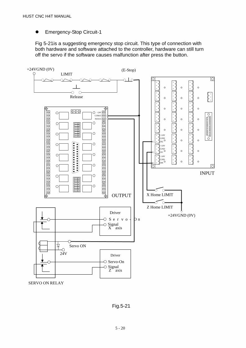
HUST CNC H4T MANUAL
5 - 20
Emergency-Stop Circuit-1 Fig 5-21is a suggesting emergency stop circuit. This type of connection with both hardware and software attached to the controller, hardware can still turn off the servo if the software causes malfunction after press the button.
Fig.5-21
+24V COM15 NOO15
OUTPUT
24V
Servo ON
SERVO ON RELAY
Driver
X axis
Servo-OnSignal
Driver
Z axis
Servo-OnSignal
INPUT
+24VGND I00
+24VGNDI01
+24VGNDI02
+24VGND (0V)
X Home LIMIT
Z Home LIMIT
+24VGND (0V) LIMIT
(E-Stop)
Release

5 CONNECTIONS
5 - 21
Emergency-Stop Circuit-2 Fig.5-22 is a simplified connection diagram.
Fig 5-22
Driver
X axis
Servo-On Signal
INPUT
+24VGND I00
+24VGNDI01
+24VGNDI02
+24VGND (0V)
X Home LIMIT
Z Home LIMIT
+24VGND (0V) LIMIT
(E-Stop)
Release
OUTPUT
+24V COM15 NOO15
+24V COM14 NOO14
Driver
Z axis
Servo-On Signal

HUST CNC H4T MANUAL
5 - 22
Servo Motor Connection Diagram (This is an example of Mitsubishi J2S Motor)
Fig.5-23
U V W
To Controller
3∅ AC 220V
Earth
To: SERVO-ON Relay

5 CONNECTIONS
5 - 23
5.4.5 Motion Control (Servo/MPG) Connection Suitable Type for H4T
The connections may vary depending on the type of servo system and the MPG that customer uses.
Fig 5-24 Servo and MPG Unit Connection
Spindle
Case Ground
Inverter
A A-
B
B-
DAC GND +5V
1 2
3
4
5 6 7 8 9
Encoder
VCMD (-10~+10V)
Servo Driver
+5V Ground Case Ground
A A- B
B- Z
Z- VCMD
+5V GND +5V
1 2
9
3 4
5 6 7 8
Z-axis
CPU Main Board
Servo Driver
VCMD (-10~+10V)+5V Ground Case Ground
A A- B
B- Z
Z- VCMD
+5V GND +5V
1 2
9
3 4
5 6 7 8
X-axis
MPG
Case Ground
1
2
3
7.8
A
B
+5V 0V
MPG

HUST CNC H4T MANUAL
5 - 24
5.4.6 AC Power System Connection
HUST internal PLC in the controller has a timer to control the servo-on delay. When the set time (about 1.5 seconds) in this timer has elapsed, an output is ON to turn on the servo motors.
5.4.7 MPG Hand-wheel Connecting Diagram
If the tool movement is in the opposite direction to the MPG hand-wheel rotation, please exchange A and B signal connections.
Fig 5-26 MPG Hand-wheel connection
CPU Main Board P3
P3 0V 0V
MPG+5V 0V A 1
2 3 4 5 6 7 8
CNC Power-on
TimeCNC Power-on
Timeservo on delay
R TS
To CPU Power supply R
To CPU Power supply T
AC220V R AC220V S
AC220V T
Servo Driver
Timer Delay Contact
Fan
power-off power-on
Power-On Relay
Power-On Timer Relay
AC 220V R T0 Servo AMP Power TB P
AC 220V S T0 Servo AMP Power TB N
Can be omitted inside dashed line
Fig 5-25 AC Power Connection to Servo Driver

5 CONNECTIONS
5 - 25
5.4.8 RS232 Connector Pin Assignment and Connecting Diagram
For the operational details of RS232 communication, please refer to H4 Operation Manual. 1. Do not exceed 15 meters for the cable connecting RS232 port and
PC. 2. The interface voltage on the PC side should be in the range 10 ~ 15V. 3. Try NOT to work in an environment where electrical noises are
common. EDM machine and electric welder are noise generators. Do not use the same power source as EDM machine or electric welder.
Fig 5-27 RS232 Connector Pin Assignment
234567
8
TXDRXDDSR
SG
CTSDTR
RTS
32
7
5
64
20
RXDTXDDTRSG
RTSDSR
CTS
DB9LM Connector
DB25LF Connector
234567
8
TXDRXDDSR
SG
CTSDTR
RTS
2345678
RXDTXDDTRSG
RTSDSR
CTS
DB9LM Connector
DB9LF Connector
Controller Side PC Side – COM1
DCE DCE
Controller Side PC Side - COM2

HUST CNC H4T MANUAL
5 - 26

6 ERROR MESSAGES
6 - 1
6 ERROR MESSAGES When an error occurs during operation, H4T controller will be stopped and an error message displayed at the top of the screen as shown in Fig 6-1. If there is more than one error, only one error will be displayed at a time. The second error will be displayed when the first problem is resolved. This chapter is to explain the error messages and the method to solve them.
Fig 6-1 Error Message Display
ERROR 1 -- MCM Data Error Or Battery Fail Message: MCM parameter setting is incorrect or the backup battery has failed. Recommended Remedy: 1. Check if MCM parameter setting data are correct. Otherwise, use "G10 P1000" to
clear all MCM data and re-enter all MCM data. Press RESET. 2. If the problem is on the battery, turn on the controller and leave it "on" for 4 hours
to recharge the backup battery. If the error persists, please contact the maintenance engineer to change out the battery. If the controller has not been turned on for a month, the data in the memory will be lost.
ERROR 2 -- Servo Alarm, Please Home Again Message: Servo position control system (servo feedback) error. Possible causes are: 1. The voltage command from the controller is too fast for the motor to response. 2. The controller does not receive any feedback signal from the servo motor. Recommended Remedy: 1. Check if the feed-rate F in the part program is too fast. 2. Check if the resolution setting of MCM parameter is correct. 3. Check if the worktable being overloaded, or any obstruction in the motor. Also
check the servo system including the connections.
Error 02. X AXIS ERR
Error Message

HUST CNC H4T MANUAL
6 - 2
ERROR 8 -- Exceed 80 Characters For One Block Message: A block of the part program exceeds 80 characters. Recommended Remedy: Check the part program and make sure each single block of program is less than 80 characters.
ERROR 10 – RS232 Error Message: There is a message signal error on the RS232 controller Recommended Remedy: 1. Check the message transmission rate on the controller to see whether PC is the
same as MMI (Man Machine Interface). 2. Check the connections from the controller to PC or the controller to MMI.
ERROR 11 -- Program Memory Error Message: Program memory error. Possible causes are: 1. Battery failure. 2. Part program is too large and exceeds memory capacity. Recommended Remedy: 1. Check and revise the program, then press RESET. 2. If the program is in serious error, use G10 P2001 to clear the program. 3. If problem is on the battery, turn on the controller and leave it "on" for at least 4
hours. If the error persists, change out the battery.
ERROR 13 -- Error G-Code Command Message: Incorrect G-code in the program. Recommended Remedy: Check the part program for the G-code that is not acceptable by Lathe controller. ERROR 14 -- X-axis Over-travel Message: The cutting tool travels beyond the hardware limit in X-axis. Recommended Remedy: Use the MPG hand-wheel to manually move the tool within the operating range in X-axis.

6 ERROR MESSAGES
6 - 3
ERROR 16 -- Z-axis Over-travel Message: The cutting tool travels beyond the hardware limit in Z-axis. Recommended Remedy: Use the MPG hand-wheel to manually move the tool within the operating range in Z-axis.
ERROR 18 -- End Of File Not Found Message: Ending error in the part program.( without M02, M30) Recommended Remedy: Check the ending statement of the part program, such as M02, M30.
ERROR 20 --Software Over-Travel Message: The cutting tool travel has reached the bounding limit as set by the software. Recommended Remedy: Check the part program or reset the items from MCM #93 to #98 for software travel limit.
ERROR 22 -- EM-Stop, Home Again Message: Controller is in emergency stop state. Recommended Remedy: Resolve the cause for emergency stop. Restore Emergency-STOP button and press RESET or HOME key before normal operation. ERROR 24 -- M98 Exceed 8 Level Message: The sub-program calls exceed 8 levels. Recommended Remedy: Revise the part program and make sure the sub-program calls do not exceed 8 levels. ERROR 25 -- Wrong Circle Format or Data Error Message: The circular cutting command or the command format is in error. Recommended Remedy: Check the part program and recalculate the coordinate of the center of the arc/circle.

HUST CNC H4T MANUAL
6 - 4
ERROR 30.1 –Battery is Low Message: The battery (BT1) for resource saving is down or malfunction in H3X/P-T series Recommended Remedy: Renew the battery (BT1). ERROR 31 -- None PLC Message: There is no PLC ladder program in FLASHROM memory. Recommended Remedy: Check the existence of PLC in FLASHROM first. ERROR 36 – RS232 Program Number is in Error Message: The RS232 number errors in the part program Recommended Remedy: Check whether the part program number is correct in DNC10. ERROR 37 -- NC Alarm Message: There is a mechanical problem from the machine tool side. Recommended Remedy: Check the machine tool for proper operation and “Reset” again after check. ERROR 50~99 Message: Users can use G65 to set their own message errors. Recommended Remedy: Check whether the setting program on G65 is correct or not.
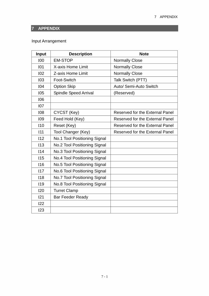
7 APPENDIX
7 - 1
7 APPENDIX Input Arrangement
Input Description Note I00 EM-STOP Normally Close I01 X-axis Home Limit Normally Close I02 Z-axis Home Limit Normally Close I03 Foot-Switch Talk Switch (PTT) I04 Option Skip Auto/ Semi-Auto Switch I05 Spindle Speed Arrival (Reserved) I06 I07 I08 CYCST (Key) Reserved for the External Panel I09 Feed Hold (Key) Reserved for the External Panel I10 Reset (Key) Reserved for the External Panel I11 Tool Changer (Key) Reserved for the External Panel I12 No.1 Tool Positioning Signal I13 No.2 Tool Positioning Signal I14 No.3 Tool Positioning Signal I15 No.4 Tool Positioning Signal I16 No.5 Tool Positioning Signal I17 No.6 Tool Positioning Signal I18 No.7 Tool Positioning Signal I19 No.8 Tool Positioning Signal I20 Turret Clamp I21 Bar Feeder Ready I22 I23

HUST CNC H4T MANUAL
7 - 2
Output Arrangement Output Description Note
O00 Spindle CW O01 Spindle CCW O02 Coolant O03 Alarm Light O04 Spindle Unclamp O05 Lubrication O06 Unclamp Light O07 O08 Tool CW O09 Tool CCW O10 O11 Bar Feeder O12 O13 Workpiece No. on O14 Servo-on X O15 Servo-on Z
M-code Versus I/O
M code Description I/O Note M03 Spindle CW 000=1 M04 Spindle CCW 001=1 M05 Spindle stop 000=0,001=0
M08 Coolant On 002=1 M09 Coolant Off 002=0 M10 Chuck On 004=1 M11 Chuck Off 004=0 M15 Counter+1 #9501+1 M16 Clear Counter

7 APPENDIX
7 - 3
Parameter of Multiple Canned Cycle
Illustration as a reference
Fig.7-1
PLC Parameters
Fig.7-2
Time- 1~4: Steps for automatic feeder: When there is an automatic bar feeder (Cylinder, Hydrometer), I04=0 M10 includes 2 procedures: a. Chuck loosen-delay (Time-1) unit /10ms, which is set by machine
manufacturers.

HUST CNC H4T MANUAL
7 - 4
b. Feed cylinder executes the process. M11 includes 2 procedures: a. Chuck tighten- (Time-2) unit/10ms, which is set by machine manufacturers. b. Feed cylinder returned. Process is complete. Time-3: feed time. The setting is based on the length of the material. Time-4: Tool clamp delay time. Tool numbers: Steps for Lathe tool changer:
1. Tool changer Clockwise O08=1 2. Turn to tool number selection INPUT, manual tool changer is the next. 3. O08=0 4. Pause 50×5=250 ms (Timer =79) 5. Tool changer counter clockwise O09=1 6. Wait for the signal of tool lock I20=1 7. Counter Clockwise Continue (Time-4) ms (timer=78) 8. O09=0, Tool changer stops. Tool numbers ≦1 & >8 Tool changer remains >1 or <8 Tool changes Two – six tool numbers can be assigned. Example: Tool numbers =5 Manual tool changer 1,2,3,4, 1, 2,3… cycle. TCODE→ tool changes. T202 → changes to the next tool and select the second set of tool compensation. T603→ Tool number remains. Because 6 is bigger than 5, it will select the third set of tool compensation instead.