Embed Size (px)
Citation preview

Lateral Load Performance of SIP Walls with Full BearingBorjen YehTom SkaggsXiping WangTom Williamson
United States Department of Agriculture
ForestService
Forest ProductsLaboratory
General Technical ReportFPL–GTR–251
January2018

AbstractThe purpose of this study was to develop test data needed to characterize lateral load performance of structural insulated panel (SIP) walls with full bearing (restrained). The research program involved structural testing of 29 full-size SIP walls (8 ft tall by 8 ft long) of various configurations that bracket a range of SIP wall configurations commonly used in the field. Results indicated that the cyclic performance param-eters for all walls tested in this study met the over-strength and ductility capacities of ICC-ES AC04, although some walls had drift capacities slightly lower than the AC04 crite-rion. The one exception was the SIP wall without any verti-cal joints, which showed a significantly low drift capacity.
Keywords: Cyclic performance, drift, ductility, full bearing, over-strength, structural insulated panel (SIP)
AcknowledgmentsThe authors thank Kelvin Liu for overseeing the test con-ducted at the APA Research Center and Alex Salenikovich of the Laval University in Quebec, Canada, for sharing his cyclic data analysis program. This work is a joint research project of APA – The Engineered Wood Association, the USDA Forest Products Laboratory, and the Structural Insu-lated Panel Association (SIPA). This research was supported in part by funds provided by the USDA Forest Products Laboratory (15-JV-11111133-041) and by the contribution of test panels by SIPA.
ContentsExecutive Summary .............................................................1
Introduction ..........................................................................1
Objective and Scope ............................................................2
Test Plan ...............................................................................2
SIP Wall Construction .......................................................2
Test Setup and Procedures ................................................8
Results and Discussion ........................................................9
Test Protocol ...................................................................10
Nail Size for Panel Connection .......................................12
Nail Spacing ....................................................................12
Wall Bearing Type ..........................................................13
Spline Type .....................................................................13
Number of Panel Joints ...................................................14
SIP Thickness ..................................................................16
Orientation of OSB Facers ..............................................16
Bottom Plate Washer Geometry......................................16
Summary and Conclusions ................................................17
Literature Cited ..................................................................18
Appendix—Hysteresis Plots of the SIP Shear WallsSubjected to CUREE Loading Protocool ...........................19January 2018
Yeh, Borjen; Skaggs, Tom; Wang, Xiping; Williamson, Tom. 2018. Lateral load performance of SIP walls with full bearing. General Technical Report FPL-GTR-251. Madison, WI: U.S. Department of Agriculture, Forest Service, Forest Products Laboratory. 23 p.A limited number of free copies of this publication are available to the public from the Forest Products Laboratory, One Gifford Pinchot Drive, Madison, WI 53726-2398. This publication is also available online at www.fpl.fs.fed.us. Laboratory publications are sent to hundreds of libraries in the United States and elsewhere.The Forest Products Laboratory is maintained in cooperation with the University of Wisconsin. The use of trade or firm names in this publication is for reader informa-tion and does not imply endorsement by the United States Department of Agriculture (USDA) of any product or service.
In accordance with Federal civil rights law and U.S. Department of Agriculture (USDA) civil rights regulations and policies, the USDA, its Agencies, offices, and employees, and institutions participating in or administering USDA programs are prohibited from discriminating based on race, color, national origin, religion, sex, gender identity (including gender expression), sexual orientation, disability, age, marital status, family/parental status, income derived from a public assistance program, political beliefs, or reprisal or retaliation for prior civil rights activity, in any program or activity conducted or funded by USDA (not all bases apply to all programs). Remedies and complaint filing deadlines vary by program or incident. Persons with disabilities who require alternative means of communication for program information (e.g., Braille, large print, audiotape, American Sign Language, etc.) should contact the responsible Agency or USDA’s TARGET Center at (202) 720–2600 (voice and TTY) or contact USDA through the Federal Relay Service at (800) 877–8339. Additionally, program information may be made available in languages other than English. To file a program discrimination complaint, complete the USDA Program Discrimination Complaint Form, AD-3027, found online at http://www.ascr.usda.gov/complaint_filing_cust.html and at any USDA office or write a letter addressed to USDA and provide in the letter all of the information requested in the form. To request a copy of the complaint form, call (866) 632–9992. Submit your completed form or letter to USDA by: (1) mail: U.S. Department of Agriculture, Office of the Assistant Secretary for Civil Rights, 1400 Independence Avenue, SW, Washington, D.C. 20250–9410; (2) fax: (202) 690–7442; or (3) email: [email protected]. USDA is an equal opportunity provider, employer, and lender.

Lateral Load Performance of SIP Walls with Full BearingBorjen Yeh, Director, Technical Services DivisionTom Skaggs, Manager, Product Evaluation, Technical Services DivisionAPA – The Engineered Wood Association, Tacoma, WashingtonXiping Wang, Research Forest Products TechnologistUSDA Forest Products Laboratory, Madison, WisconsinTom Williamson, Technical Committee ChairStructural Insulated Panel Association, Fort Lauderdale, Florida
Executive SummaryStructural insulated panels (SIPs), as defined in ANSI/APA PRS 610.1, are a structurally strong and energy-efficient construction system that utilizes the strength of wood structural panels (WSPs) and thermal energy attributes of foam plastic insulation to provide cost-effective solutions for compliance with the governing building codes. How-ever, the acceptance of SIPs by many design professionals has been hindered by the lack of a systematical evaluation of their lateral load performance in wall applications. As SIP walls are required to bear on the cap and sill plates (so-called restrained) so that vertical loads from the story above can be transferred to the story below or to the foundation, it is imperative that the lateral load performance of SIP walls reflects this configuration because this is representative of how SIP walls are constructed in the field. Unfortunately, most SIP walls have historically been evaluated by testing in a manner similar to conventional light-frame walls such that the oriented strandboard (OSB) facers are not allowed to bear on either cap plate or sill plate (so-called unrestrained), and therefore the actual lateral performance of SIP walls may not have been realistically characterized.
Based on a limited study conducted by APA in 2010, the restrained SIP walls seemed to have a significantly higher over-strength factor and lower ductility than conventionally framed wood walls. These research results led to the devel-opment of a lateral load test method specified in ANSI/APA PRS 610.1 for the qualification of SIP walls. However, the APA Standards Committee on ANSI/APA PRS 610.1 was concerned about the use of the test method for the develop-ment of SIP lateral load design values because of the lack of sufficient data for a comprehensive evaluation.
The purpose of this study was to develop test data needed to characterize the lateral load performance of SIP walls with full bearing (restrained). The research program involved structural testing of 29 full-size SIP walls (8 ft tall by 8 ft long) of various configurations that bracket a range of SIP wall configurations commonly used in the field.
Based on results obtained from this study, the lateral load resistance of SIP walls fabricated with various configura-tions tested in this study performed well when evaluated in accordance with the cyclic performance parameters of over-strength, drift, and ductility capacities, as defined in International Code Council Evaluation Service (ICC-ES) Acceptance Criteria AC04 and ASTM D7989, equivalent to light-frame walls. The only exception was the SIP wall without vertical joints in the wall, which had a significantly low drift capacity.
IntroductionStructural insulated panels (SIPs), as defined in ANSI/APA PRS 610.1 (ANSI/APA 2013), are a structurally strong and energy-efficient construction system that utilizes the strength of wood structural panels (WSPs) and thermal energy attributes of foam plastic insulation to provide cost-effective solutions for compliance with the governing building codes. However, the acceptance of SIPs by many design professionals has been hindered by the lack of a sys-tematical evaluation of their lateral load performance in wall applications. As SIP walls are required to bear on the cap and sill plates (so-called restrained) so that vertical loads from the story above can be transferred to the story below or to the foundation, it is imperative that the lateral load performance of SIP walls reflects this configuration because this is representative of how SIP walls are constructed in the field. Unfortunately, most SIP walls have historically been evaluated by testing in a manner similar to conventional light-frame walls such that the oriented strandboard (OSB) facers are not allowed to bear on either cap plate or sill plate (so-called unrestrained), and therefore the actual lateral performance of SIP walls may not have been realistically characterized.
In a 2010 pilot study by APA, as documented in APA Report T2010P-17 (APA 2010), in conjunction with the Structural Insulated Panel Association (SIPA), full-size SIP walls (two SIP panels of 4-1/2-in.-thick by 4 ft wide by 8 ft tall) were tested in accordance with both monotonic and cyclic loading

General Technical Report FPL–GTR–251
2
protocols with the SIP walls constructed to bear on wood cap and sill plates. It was noted that the SIP walls so con-structed have a significantly higher over-strength factor and lower ductility than conventional light-frame walls. These research results led to the development of a lateral load test method specified in ANSI/APA PRS 610.1 for the qualifica-tion of SIP walls. However, the APA Standards Committee on ANSI/APA PRS 610.1 (ANSI/APA 2013) was concerned about the use of the test method for development of SIP lateral load design values because of the lack of sufficient data for a comprehensive evaluation.
Objective and ScopeThe purpose of this research was to develop test data needed to characterize the lateral load performance of SIP walls with full bearing (restrained). The research program in-volved structural testing of 29 full-size SIP walls of various configurations that bracket a range of SIP wall configura-tions commonly used in the field. Only restrained configura-tions were tested in this project because the comparison with unrestrained configurations had been previously evaluated in the 2010 study (APA 2010). The following SIP wall vari-ables were examined:
1. Test protocol (monotonic and cyclic)
2. Nail size for panel connection (8d Box and 8d Common)
3. Nail spacing (6 in., 4 in., and 3 in.)
4. Wall bearing type (wood and steel bearing)
5. Spline type (block spline and two 2× lumber spline)
6. Number of panel joints (no joint, one joint, two joints, and three joints)
7. SIP thickness (4-1/2 in. and 6-1/2 in.)
8. Orientation of OSB facers (strength axis horizontal and vertical)
9. Bottom plate washer geometry (square, large round, and small round)
The results obtained from this testing were intended to pro-vide engineering information for the design of SIP walls as lateral load resisting systems.
Test PlanSIP Wall ConstructionThe test matrix encompassing the key variables is provided in Table 1. All walls tested were 8 ft tall by 8 ft long. The specific construction details for the individual walls are described below for different wall series.
Wall 1a—Construction followed the “basic wall” construc-tion (Wall 2a). Wall 1a included one replication and was tested following the ASTM E72 test method, which is
monotonic. This wall configuration is shown in Figure 1; however, the HDQ-8 holddown was not used for this wall because overturning restraint was provided by rods, as described in ASTM E72.
Wall 1b—Construction followed the “basic wall” construc-tion (Wall 2a). Wall 1b included two replications and was tested following ASTM E564 test method, which is a mono-tonic test. This wall configuration is shown in Figure 1.
“Trial” Wall—Construction followed the “basic wall” construction (Wall 2a). This wall was used as a preliminary test, hence the name, “trial.” The only difference between this wall and Wall 2a was that the strength axis of the OSB facers was oriented horizontally (i.e., cross-oriented OSB).
Wall 2a, “Basic Wall”—This construction is the control case for the different variables studied. Wall 2a included three replications and was tested following the ASTM E2126 CUREE test protocol (ASTM 2011) in reversed cyclic. The wall configuration was constructed from two 48- by 96-in. SIP segments, as shown in Figure 2. The strength axis of the OSB facer was oriented vertically. The overall SIP thickness was 4-1/2 in. The vertical joint between the two SIP panels was connected with a nominal 4× block spline. The top and bottom plates of the SIPs were 2×4 No. 2 and Better untreated Spruce–Pine–Fir (SPF). The top and bottom of each wall assembly were capped with 2×6 No. 2 and Better untreated SPF pieces, which were trimmed to match the overall SIP wall thickness. The facers were nailed with 8d Box nails (0.113 by 2-1/2 in.), spaced at 6 in. on center on the SIP panel perimeters, and nailed into framing from both sides of the wall. The walls had external HDQ-8 holddowns, attached with 12 evenly spaced 1/4- by 3-in. self-tapping/drilling lag screws, as shown in Figure 3. The double 2×4 end posts were stitched together with 12 evenly spaced 1/4- by 3-in. self-tapping/drilling lag screws, also shown in Figure 3. Two 5/8-in.-diameter anchor bolts were placed on the recessed 2×4 bottom plate at the cen-ter of each SIP segment. The basic wall used a 0.229- by 3- by 3-in. square washer at each anchor bolt, as shown in Figure 4a.
Wall 2b —This wall was built identical to Wall 2a with two deviations: (1) the anchor bolt washers were 0.229-in. by 3-in.-diameter round washers, and (2) the strength axis of the OSB facer was oriented horizontally (i.e., cross-orient-ed). The round anchor bolt washers are shown in Figure 4b. There was one replication of Wall 2b.
Wall 2c —This wall was built identical to Wall 2a with two deviations: (1) the anchor bolt washers were 0.134-in. by 1.75-in.-diameter standard cut round washers, which corresponded to the 5/8-in. washer from table L6 in the 2015 NDS, and (2) the strength axis of the OSB facer was oriented horizontally (i.e., cross-oriented). The round anchor bolt washers are shown in Figure 4c. There was one replica-tion of Wall 2c.

Lateral Load Performance of SIP Walls with Full Bearing
3
Tabl
e 1.
Tes
t mat
rix fo
r str
uctu
ral t
estin
g of
full-
size
SIP
wal
ls o
f var
ious
con
figur
atio
ns
Test
ID
SIP
segm
ent
size
(in)
SIP
thic
knes
s (in
.)Te
st
prot
ocol
No.
of
repl
icat
esSp
line
type
SIP
top/
botto
m
plat
eC
ap p
late
Sill
plat
eN
ail t
ype
Edge
nai
l sp
acin
g (in
.)
1a
48 ×
96
4.5
AST
M E
72
(mon
oton
ic)
1
4× b
lock
2×4
No.
2
& B
TR S
PF
(unt
reat
ed)
2×6
No.
2 &
BTR
SP
F (u
ntre
ated
), tri
mm
ed to
mat
ch
thic
knes
s of S
IP
2×6
No.
2 &
BTR
SP
F (u
ntre
ated
), tri
mm
ed to
mat
ch
thic
knes
s of S
IP
8d B
ox
(0.1
13 ×
2.5
in.)
6
1bA
STM
E56
4 (m
onot
onic
)2
Tria
l
AST
M
E212
6 (c
yclic
)
12a
32b
12c
13a
28d
Com
mon
(0
.131
× 2
.5 in
.) 4a
2
8d B
ox
(0.1
13 ×
2.5
in.)
34b
24
5a2
Stee
l pla
te
6
6a2
(2) 2
×4 lu
mbe
r2×
6 N
o. 2
& B
TR
SPF
(unt
reat
ed),
trim
med
to m
atch
th
ickn
ess o
f SIP
7a96
× 9
62
No
verti
cal j
oint
7b32
× 9
62
4× b
lock
7c24
× 9
62
8a48
× 9
66.
52
6× b
lock
2×6
No.
2
& B
TR S
PF
(unt
reat
ed)
2×8
No.
2 &
BTR
SP
F (u
ntre
ated
), tri
mm
ed to
mat
ch
thic
knes
s of S
IP
2×8
No.
2 &
BTR
SP
F (u
ntre
ated
), tri
mm
ed to
mat
ch
thic
knes
s of S
IP
9a48
× 9
64.
52
4× b
lock
2×4
No.
2
& B
TR S
PF
(unt
reat
ed)
2×6
No.
2 &
BTR
SP
F (u
ntre
ated
), tri
mm
ed to
mat
ch
thic
knes
s of S
IP
2×6
No.
2 &
BTR
SP
F (u
ntre
ated
), tri
mm
ed to
mat
ch
thic
knes
s of S
IP

General Technical Report FPL–GTR–251
4
Wall 3a—This wall was built identical to Wall 2a with one deviation: the facers were nailed with 8d Common nails (0.131 by 2-1/2 in.), spaced at 6 in. on center on the SIP panel perimeters and nailed into framing from both sides of the wall. There were two replications of Wall 3a.
Wall 4a—This wall was built identical to Wall 2a with three deviations: (1) the nail spacing on the 8d Box facer nails was at 3 in. on center on the SIP panel perimeters, (2) the HDQ-8 holddowns were attached with 20 1/4- by 3-in. self-tapping/drilling lag screws, and (3) the double 2×4 end posts were stitched together with 22 evenly spaced 1/4- by 3-in. self-tapping/drilling lag screws. There were two replications of Wall 4a.
Wall 4b—This wall was built identical to Wall 2a with three deviations: (1) the nail spacing on the 8d Box facer nails was at 4 in. on center on the SIP panel perimeters, (2) the HDQ-8 holddowns were attached with 16 1/4- by 3-in. self-tapping/drilling lag screws, and (3) the double 2×4 end posts were stitched together with 16 evenly spaced 1/4- by 3-in.
self-tapping/drilling lag screws. There were two replications of Wall 4b.
Wall 5a—This wall was built identical to Wall 2a with two deviations: (1) the SIP edge nailing into the block spline that was used to connect the SIPs together had nails at 12 in. on center, and (2) the bottom of the wall assembly, the recessed 2×4 bottom plate, and the OSB facers were bearing directly onto a rigid steel channel. There were two replications of Wall 5a.
Wall 6a—This wall was built identical to Wall 2a with one deviation: the vertical joint between the two SIP panels was connected with two 2×4 lumber studs stitched together with twelve 1/4- by 3-in. self-tapping/drilling lag screws. There were two replications of Wall 6a.
Wall 7a—This wall was built identical to Wall 2a with one deviation: the wall contained no vertical joints and consisted of one SIP panel with dimensions of 96 by 96 in. There were two replications of Wall 7a. This wall configuration is shown in Figure 5a.
Figure 1. Configuration of Walls 1a and 1b, monotonic E72 (one replication) and E564 loading (two replications), control wall.
HDQ-8 holddown12× SDS screwsevenly spaced(ASTM E564 only)3/4" bolt
Two 2×4 end posts12× SDS screws~6.5" spacingstaggered in both directions
Two 2×4 end posts12× SDS screws
~6.5" spacingstaggered in both
directions
6" o.c. nail spacing(3/8" from edge)both sides8d Box nails
Load head>10× SDS screwsevenly spaced
Wall 1Monotonic loadingThree replications
6" o.c. nail spacing(3/8" from edge)both sides8d Box nails
4× block spline provided
1/8" gap between panels
6" o.c. nail spacing(3/8" from edge)both sides8d Box nails
6" o.c. nail spacing(3/8" from edge)
both sides8d Box nails
5/8" boltBore 1" deep hole in foam
2×6 untreated SPF cap plate (No. 2 & BTR)
5/8" boltBore 1" deep hole in foam
2×6 untreated SPF (or equiv.) sill plate(No. 2 & BTR)
2'2'
8'
8'6"8'
8'

Lateral Load Performance of SIP Walls with Full Bearing
5
Wall 7b—This wall was built identical to Wall 2a with one deviation: the wall contained two vertical joints and was constructed with three SIP segments with dimensions of 32 by 96 in. each. Block splines were used to connect the SIPs together on the vertical joints. Anchor bolts were centered on each of the three SIP segments. There were two replica-tions of Wall 7b. This wall configuration is shown in Figure 5b.
Wall 7c—This wall was built identical to Wall 2a with one deviation: the wall contained three vertical joints and was constructed with four SIP segments with dimensions of 24 by 96 in. each. Block splines were used to connect the SIPs together on the vertical joints. Anchor bolts were centered on each of the four SIP segments. There were two replications of Wall 7c. This wall configuration is shown in Figure 5c.
Wall 8a—This wall was built identical to Wall 2a with the following deviations related to thicker SIPs: (1) the over-all SIP thickness was 6-1/2 in., (2) the only vertical joint
Figure 2. Configuration of Wall 2a, CUREE cyclic protocol, basic wall (three replications). Walls 2b (one replication) and 2c (one replication) were similar construction, but OSB facers were cross-oriented, and anchor bolt washer sizes varied.
Figure 3. External HDQ-8 holddown.
HDQ-8 holddown12× SDS screwsevenly spaced
3/4" bolt
HDQ-8 holddown12× SDS screws
evenly spaced
3/4" bolt
Two 2×4 end posts12× SDS screws~6.5" spacingstaggered in both directions
Two 2×4 end posts12× SDS screws
~6.5" spacingstaggered in both
directions
6" o.c. nail spacing(3/8" from edge)both sides8d Box nails
Load head>10× SDS screwsevenly spaced
Wall 2Cyclic loading
Three replications
6" o.c. nail spacing(3/8" from edge)both sides8d Box nails
4× block spline provided
1/8" gap between panels
6" o.c. nail spacing(3/8" from edge)both sides8d Box nails
6" o.c. nail spacing(3/8" from edge)
Both sides8d box nails
5/8" boltBore 1" deep hole in foam
2×6 untreated SPF cap plate (No. 2 & BTR)
5/8" boltBore 1" deep hole in foam
2×6 untreated SPF (or equiv.) sill plate(No. 2 & BTR)
2'2'
8'
8'6"8'
8'

General Technical Report FPL–GTR–251
6
Figure 4. Washers used for anchor bolts: (a) square washer; (b) large round washer; (c) standard cut round washer.
Figure 5. Configuration of Wall 7 series: (a) Wall 7a, 8-ft by 8-ft SIP segment (two replications); (b) Wall 7b, three 32-in. by 8-ft SIP segments, three anchor bolts (two replications); and (c) Wall 7c, four 24-in. by 8-ft SIP segments, four anchor bolts (two replications).
between the two SIP panels was connected with a nominal 6× block spline, (3) the top and bottom plates of the SIPs were 2×6 No. 2 and Better untreated SPF, and (4) the top and bottom of the wall assembly were capped with 2×8 No. 2 and Better SPF pieces, which were trimmed to match the overall SIP wall thickness. There were two replications of Wall 8a.
Wall 9a—This wall was built identical to Wall 2a with one deviation: the strength axes of the OSB facers were oriented horizontally (i.e., cross-oriented). There were two replica-tions of Wall 9a.
(a) (b) (c)
HDQ-8 holddown12× SDS screwsevenly spaced
3/4" bolt
HDQ-8 holddown12× SDS screws
evenly spaced
3/4" bolt
Two 2×4 end posts12× SDS screws~6.5" spacingstaggered in both directions
Two 2×4 end posts12× SDS screws
~6.5" spacingstaggered in both
directions
6" o.c. nail spacing(3/8" from edge)both sides8d Box nails
Load head>10× SDS screwsevenly spaced
Wall 7bCyclic loading
Two replications
6" o.c. nail spacing(3/8" from edge)both sides8d Box nails
Box spline provided
Box spline provided
1/8" gap between panels
1/8" gap between panels
6" o.c. nail spacing
(3/8" from edge)both sides
8d Box nails6" o.c. nail
spacing(3/8" from edge)
both sides8d Box nails
6" o.c. nail spacing
(3/8" from edge)both sides
8d Box nails
5/8" boltBore 1" deep hole in foam
2×6 untreated SPF (or equiv.) sill plate(No. 2 & BTR)
8'
8'6"8'
8'
2' 7-1/2"2' 7-1/2"1' 4-1/2" 1' 4-1/2"
HDQ-8 holddown12× SDS screwsevenly spaced
3/4" bolt
HDQ-8 holddown12× SDS screws
evenly spaced
3/4" bolt
Two 2×4 end posts12× SDS screws~6.5" spacingstaggered in both directions
Two 2×4 end posts12× SDS screws
~6.5" spacingstaggered in both
directions
6" o.c. nail spacing(3/8" from edge)both sides8d Box nails
Load head>10× SDS screwsevenly spaced
Wall 7aCyclic loading
Two replications
6" o.c. nail spacing(3/8" from edge)both sides8d Box nails6" o.c. nail
spacing(3/8" from edge)
both sides8d Box nails
5/8" boltBore 1" deep hole in foam
5/8" boltBore 1" deep hole in foam
2×6 untreated SPF cap plate (No. 2 & BTR)
3/4" spacing from stud end last nail
2×6 untreated SPF (or equiv.) sill plate(No. 2 & BTR)
8'
8'6"8'
8'
2' 2'
8' × 8' segment
2×6 untreated SPF cap plate (No. 2 & BTR)
3/4" spacing from stud end last nail
HDQ-8 holddown12× SDS screwsevenly spaced
3/4" bolt
HDQ-8 holddown12× SDS screws
evenly spaced
3/4" bolt
Two 2×4 end posts12× SDS screws~6.5" spacingstaggered in both directions
Two 2×4 end posts12× SDS screws
~6.5" spacingstaggered in both
directions
6" o.c. nail spacing(3/8" from edge)both sides8d Box nails
Load head>10× SDS screwsevenly spaced
Wall 7cCyclic loading
Two replications
6" o.c. nail spacing(3/8" from edge)both sides8d Box nails
Box spline provided
6" o.c. nail spacing
(3/8" from edge)both sides
8d Box nails
6" o.c. nail spacing
(3/8" from edge)
both sides
8d Box nails
6" o.c. nail spacing
(3/8" from edge)
both sides
8d Box nails
6" o.c. nail spacing
(3/8" from edge)
both sides
8d Box nails
5/8" boltBore
1" deep hole in
foam
2×6 untreated SPF (or equiv.) sill plate(No. 2 & BTR)
8'
8'6"8'
8'
2'1' 11-1/2" 1' 11-1/2"1' 1/2" 1' 1/2"
2×6 untreated SPF cap plate (No. 2 & BTR)
3/4" spacing from stud end last nail
(a)
(b)
(c)

Lateral Load Performance of SIP Walls with Full Bearing
7
Figure 5 (con.). Configuration of Wall 7 series: (a) Wall 7a, 8-ft by 8-ft SIP segment (two replications); (b) Wall 7b, three 32-in. by 8-ft SIP segments, three anchor bolts (two replications); and (c) Wall 7c, four 24-in. by 8-ft SIP segments, four anchor bolts (two replications).
HDQ-8 holddown12× SDS screwsevenly spaced
3/4" bolt
HDQ-8 holddown12× SDS screws
evenly spaced
3/4" bolt
Two 2×4 end posts12× SDS screws~6.5" spacingstaggered in both directions
Two 2×4 end posts12× SDS screws
~6.5" spacingstaggered in both
directions
6" o.c. nail spacing(3/8" from edge)both sides8d Box nails
Load head>10× SDS screwsevenly spaced
Wall 7bCyclic loading
Two replications
6" o.c. nail spacing(3/8" from edge)both sides8d Box nails
Box spline provided
Box spline provided
1/8" gap between panels
1/8" gap between panels
6" o.c. nail spacing
(3/8" from edge)both sides
8d Box nails6" o.c. nail
spacing(3/8" from edge)
both sides8d Box nails
6" o.c. nail spacing
(3/8" from edge)both sides
8d Box nails
5/8" boltBore 1" deep hole in foam
2×6 untreated SPF (or equiv.) sill plate(No. 2 & BTR)
8'
8'6"8'
8'
2' 7-1/2"2' 7-1/2"1' 4-1/2" 1' 4-1/2"
HDQ-8 holddown12× SDS screwsevenly spaced
3/4" bolt
HDQ-8 holddown12× SDS screws
evenly spaced
3/4" bolt
Two 2×4 end posts12× SDS screws~6.5" spacingstaggered in both directions
Two 2×4 end posts12× SDS screws
~6.5" spacingstaggered in both
directions
6" o.c. nail spacing(3/8" from edge)both sides8d Box nails
Load head>10× SDS screwsevenly spaced
Wall 7aCyclic loading
Two replications
6" o.c. nail spacing(3/8" from edge)both sides8d Box nails6" o.c. nail
spacing(3/8" from edge)
both sides8d Box nails
5/8" boltBore 1" deep hole in foam
5/8" boltBore 1" deep hole in foam
2×6 untreated SPF cap plate (No. 2 & BTR)
3/4" spacing from stud end last nail
2×6 untreated SPF (or equiv.) sill plate(No. 2 & BTR)
8'
8'6"8'
8'
2' 2'
8' × 8' segment
2×6 untreated SPF cap plate (No. 2 & BTR)
3/4" spacing from stud end last nail
HDQ-8 holddown12× SDS screwsevenly spaced
3/4" bolt
HDQ-8 holddown12× SDS screws
evenly spaced
3/4" bolt
Two 2×4 end posts12× SDS screws~6.5" spacingstaggered in both directions
Two 2×4 end posts12× SDS screws
~6.5" spacingstaggered in both
directions
6" o.c. nail spacing(3/8" from edge)both sides8d Box nails
Load head>10× SDS screwsevenly spaced
Wall 7cCyclic loading
Two replications
6" o.c. nail spacing(3/8" from edge)both sides8d Box nails
Box spline provided
6" o.c. nail spacing
(3/8" from edge)both sides
8d Box nails
6" o.c. nail spacing
(3/8" from edge)
both sides
8d Box nails
6" o.c. nail spacing
(3/8" from edge)
both sides
8d Box nails
6" o.c. nail spacing
(3/8" from edge)
both sides
8d Box nails
5/8" boltBore
1" deep hole in
foam
2×6 untreated SPF (or equiv.) sill plate(No. 2 & BTR)
8'
8'6"8'
8'
2'1' 11-1/2" 1' 11-1/2"1' 1/2" 1' 1/2"
2×6 untreated SPF cap plate (No. 2 & BTR)
3/4" spacing from stud end last nail
(a)
(b)
(c)
HDQ-8 holddown12× SDS screwsevenly spaced
3/4" bolt
HDQ-8 holddown12× SDS screws
evenly spaced
3/4" bolt
Two 2×4 end posts12× SDS screws~6.5" spacingstaggered in both directions
Two 2×4 end posts12× SDS screws
~6.5" spacingstaggered in both
directions
6" o.c. nail spacing(3/8" from edge)both sides8d Box nails
Load head>10× SDS screwsevenly spaced
Wall 7bCyclic loading
Two replications
6" o.c. nail spacing(3/8" from edge)both sides8d Box nails
Box spline provided
Box spline provided
1/8" gap between panels
1/8" gap between panels
6" o.c. nail spacing
(3/8" from edge)both sides
8d Box nails6" o.c. nail
spacing(3/8" from edge)
both sides8d Box nails
6" o.c. nail spacing
(3/8" from edge)both sides
8d Box nails
5/8" boltBore 1" deep hole in foam
2×6 untreated SPF (or equiv.) sill plate(No. 2 & BTR)
8'
8'6"8'
8'
2' 7-1/2"2' 7-1/2"1' 4-1/2" 1' 4-1/2"
HDQ-8 holddown12× SDS screwsevenly spaced
3/4" bolt
HDQ-8 holddown12× SDS screws
evenly spaced
3/4" bolt
Two 2×4 end posts12× SDS screws~6.5" spacingstaggered in both directions
Two 2×4 end posts12× SDS screws
~6.5" spacingstaggered in both
directions
6" o.c. nail spacing(3/8" from edge)both sides8d Box nails
Load head>10× SDS screwsevenly spaced
Wall 7aCyclic loading
Two replications
6" o.c. nail spacing(3/8" from edge)both sides8d Box nails6" o.c. nail
spacing(3/8" from edge)
both sides8d Box nails
5/8" boltBore 1" deep hole in foam
5/8" boltBore 1" deep hole in foam
2×6 untreated SPF cap plate (No. 2 & BTR)
3/4" spacing from stud end last nail
2×6 untreated SPF (or equiv.) sill plate(No. 2 & BTR)
8'
8'6"8'
8'
2' 2'
8' × 8' segment
2×6 untreated SPF cap plate (No. 2 & BTR)
3/4" spacing from stud end last nail
HDQ-8 holddown12× SDS screwsevenly spaced
3/4" bolt
HDQ-8 holddown12× SDS screws
evenly spaced
3/4" bolt
Two 2×4 end posts12× SDS screws~6.5" spacingstaggered in both directions
Two 2×4 end posts12× SDS screws
~6.5" spacingstaggered in both
directions
6" o.c. nail spacing(3/8" from edge)both sides8d Box nails
Load head>10× SDS screwsevenly spaced
Wall 7cCyclic loading
Two replications
6" o.c. nail spacing(3/8" from edge)both sides8d Box nails
Box spline provided
6" o.c. nail spacing
(3/8" from edge)both sides
8d Box nails
6" o.c. nail spacing
(3/8" from edge)
both sides
8d Box nails
6" o.c. nail spacing
(3/8" from edge)
both sides
8d Box nails
6" o.c. nail spacing
(3/8" from edge)
both sides
8d Box nails
5/8" boltBore
1" deep hole in
foam
2×6 untreated SPF (or equiv.) sill plate(No. 2 & BTR)
8'
8'6"8'
8'
2'1' 11-1/2" 1' 11-1/2"1' 1/2" 1' 1/2"
2×6 untreated SPF cap plate (No. 2 & BTR)
3/4" spacing from stud end last nail
(a)
(b)
(c)

General Technical Report FPL–GTR–251
8
Figure 6. ASTM E72 monotonic test setup.
Figure 7. ASTM E72 monotonic test setup: (a) holddown rods and roller to resist overturning; (b) monotonic load head.
Test Setup and ProceduresWall 1a was tested following a monotonic procedure speci-fied in section 4.5 of ICC-ES Acceptance Criteria AC04 (ICC-ES 2015), which references ASTM E72 (ASTM 2015b). Figure 6 shows the monotonic test setup. Figure 7a shows the holddown rods and rollers to resist overturning, and Figure 7b shows the monotonic load head.
In accordance with section 4.5.5 of ICC-ES AC04, the ASTM E72 “stop” was detailed such that it was bearing on the end of the bottom trimmed 2×6 cap plate, and the loading was applied directly to the top plate of the wall in tension in a load-control mode. The loading was applied at a constant rate as follows:
1. Wall is loaded to the test load (300 pounds per lineal foot (plf)) in 5 min
2. Wall is unloaded to zero load in 1 min
3. Wall is held at zero load for 5 min
4. Wall is loaded to two times test load (600 plf) in 5 min
5. Wall is unloaded to zero load in 1 min
6. Wall is held at zero load for 5 min
7. Wall is loaded to ultimate load. Loading is applied at a rate such that 2.5 times test load (750 plf) is achieved in 5 min
ASTM E72 permits the top of wall deflection to be reduced by the uplift deflection and the lateral translation deflection. The data reported for the monotonic tests are based on this
net top of wall displacement as well as the gross deflection, which more closely corresponds to ASTM E564 procedure (ASTM 2012).
Wall 1b was tested following a monotonic test in accordance with ASTM E564 (ASTM 2012). The data reported are based on the top of wall deflection.
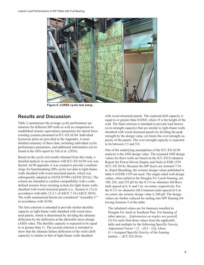
The rest of the walls were subjected to a cyclic loading protocol following ASTM E2126, Method C, CUREE Basic Loading Protocol (ASTM 2011). Figure 8 shows the cyclic test setup. The reference deflection, Δ, was set as 2.4 in. Each subsequent phase of the CUREE protocol consisted of a primary cycle with an increase in an amplitude of α of 0.5 over the previous primary cycle. Additional cycles were added to the protocol for a potential maximum displacement applied to the wall of ±9.6 in. The tests were terminated when a significant loss in load was noted. This testing pro-cedure, including the terms for Δ and α, was based on APA’s past experience with cyclic testing of wood structural panel shear walls. The displacement-based protocol was applied to the wall at 0.5 Hz.
(a)
(b)
Lateral Load Performance of SIP Walls with Full Bearing
9
Figure 8. CUREE cyclic test setup.
Results and DiscussionTable 2 summarizes the average cyclic performance pa-rameters for different SIP walls as well as comparison to established seismic equivalency parameters for lateral force resisting systems presented in ICC-ES AC04. Individual hysteresis plots are provided in the Appendix. A more detailed summary of these data, including individual cyclic performance parameters, and additional information can be found in the APA report by Yeh et al. (2016).
Based on the cyclic test results obtained from this study, a detailed analysis in accordance with ICC-ES AC04 was con-ducted. AC04 appendix A was created to provide a method-ology for benchmarking SIPs cyclic test data to light-frame walls sheathed with wood structural panels, which was subsequently adopted in ASTM D7989 (ASTM 2015a). The criteria are intended to confirm compatibility with a code-defined seismic-force resisting system for light-frame walls sheathed with wood structural panels (i.e., System A-13) in accordance with table 12-2.1 of ASCE 7-10 (ASCE 2010). The walls summarized herein are considered “Assembly C” in accordance with AC04.
The first criterion is intended to provide similar ductility capacity as light-frame walls sheathed with wood struc-tural panels, which is determined by dividing the ultimate deflection by the deflection at the allowable stress design (ASD) value. The ductility capacity is expected to be equal to or greater than 11. The second criterion is intended to show that the ultimate failure deflection of the walls (drift capacity) is similar to that of light-frame walls sheathed
with wood structural panels. The expected drift capacity is equal to or greater than 0.028H, where H is the height of the wall. The final criterion is intended to provide load factors (over-strength capacity) that are similar to light-frame walls sheathed with wood structural panels by dividing the peak strength by the design value, yet limits the over-strength ca-pacity of the panels. The over-strength capacity is expected to be between 2.5 and 5.0.
One of the underlying assumptions of the ICC-ES AC04 analysis is the ASD design value. The assumed ASD design values for these walls are based on the ICC-ES Evaluation Report for Power-Driven Staples and Nails in ESR-1539 (ICC-ES 2016). Because the SIP facers are nominal 7/16-in. Rated Sheathing, the seismic design values published in table 8 of ESR-1539 are used. The single-sided wall design values, when nailed to the Douglas Fir–Larch framing, are 180, 265, and 335 plf for the 0.113-in.-diameter (8d Box) nails spaced at 6, 4, and 3 in. on center, respectively. For the 0.131-in.-diameter (8d Common) nails spaced at 6 in. on center, the seismic design value is 240 plf. The design values are further reduced for nailing into SPF framing fol-lowing footnote 4 of the table:
The tabulated values are for fasteners installed in Douglas Fir–larch or Southern Pine. For framing of other species …[information on staples not quoted] (3) For nails find shear values from the applicable table and multiple by the following Specific Gravity Adjustment Factor = [1 – (0.5 – G)], where G = Assigned Specific Gravity of the framing lumber… (ICC-ES 2016)

General Technical Report FPL–GTR–251
10
Table 2. Mean cyclic performance parameters from walls tested and analyzed in accordance with ICC-ES AC04
Wall Replicates
ASD design valuea (plf)
ASD design deflectionb
(in.)
Ultimate deflectionb
(in.)
Peak loadb (plf)
ICC ES AC04 analysis section number
A3.3.2c ductility capacity
A3.3.3d drift
capacity
A3.3.4e over-strength
capacity
Trial 1 331 0.083 2.47 1,034 29.8 0.026H 3.12Wall 2a 3 331 0.113 2.83 1,188 28.5 0.029H 3.59Wall 2b 1 331 0.156 3.00 965 19.2 0.031H 2.91Wall 2c 1 331 0.167 3.32 965 19.8 0.035H 2.91Wall 3a 2 442 0.133 2.58 1,204 20.0 0.027H 2.73Wall 4a 2 616 0.203 2.63 1,876 13.0 0.028H 3.04Wall 4b 2 488 0.171 2.62 1,504 15.3 0.028H 3.08Wall 5a 2 331 0.128 2.72 1,024 21.7 0.029H 3.09Wall 6a 2 331 0.079 2.55 1,149 32.3 0.027H 3.47Wall 7a 2 331 0.063 2.00 1,314 31.9 0.021H 3.97Wall 7b 2 331 0.112 3.70 1,052 33.6 0.039H 3.18Wall 7c 2 331 0.143 5.00 986 35.7 0.052H 2.98Wall 8a 2 331 0.116 3.54 1,110 31.1 0.037H 3.35Wall 9a 2 331 0.083 2.45 1,097 29.7 0.026H 3.31aSee Test Plan of this report for more details on wall construction. Allowable design values are based on the seismic shear wall values for 0.113- and 0.131-in.-diameter nails with 7/16-in. (nominal) rated sheathing, as published in table 8 of ICC-ES ESR-1539, multiplied by 2 for double sided nailing. The values were further modified for nailing into Spruce–Pine–Fire (SPF) lumber based on footnote 4 to table 8 of ESR-1539.bBased on the average of the absolute value of positive and negative cyclic excursion.cUltimate deflection divided by deflection at design value (ductility capacity). ICC-ES AC04 appendix A requires this property to be equal to or greater than 11.dMinimum post peak displacement (drift capacity). AC04 appendix A requires this property to be equal to or greater than 0.028H, where H is the height of the wall, based on tests following the CUREE loading protocol.ePeak strength divided by design value (over-strength capacity). AC04 appendix A requires this property to be between 2.5 and 5.0.
For SPF framing, G = 0.42 in accordance with NDS. Therefore, the Specific Gravity Adjustment Factor = 0.92. Because the SIP walls were nailed on both sides, the ASD values in table 8 of ESR-1539 are doubled. For the 0.113-in.-diameter (8d Box) nails, the design value is 331, 488, and 616 plf for nails spaced at 6, 4, and 3 in. on center, respectively. For the 0.131-in.-diameter (8d Common) nails spaced at 6 in. on center, the design value is 442 plf.
Based on the information presented in Table 2, all walls tested in this study met the AC04 cyclic performance criteria with the exception of some wall configurations that dem-onstrated less than the required drift capacity of 0.028H. Additional discussion on the cyclic performance parameters and how they were affected by the wall configuration is provided in the sections following.
Test ProtocolFigure 9 shows backbone curves from three replications of the basic wall configuration, Wall 2a. The hysteresis loops for Wall 2a are shown in Appendix A2–A4. Figure 9 also shows the monotonic results from Walls 1a (ASTM E72) and 1b (ASTM E564), based on the wall gross deflection
(i.e., top of wall deflection without adjustments for uplift and sliding in accordance with ICC-ES AC04 and ASTM E72).
Figure 10 shows the amount of uplift occurring during the ASTM E72 monotonic tests. Figure 11 shows the typical failure modes that were observed during the ASTM E2126 cyclic tests and failure of the connection of the top plate to the studs.
According to Figure 9, the mean ultimate load value for Wall 2a was 1,188 plf based on the mean positive loads and the absolute value of the mean negative peak loads. The ultimate load for Wall 1a and 1b was 1,175 plf and 1,062 plf, respectively. Figure 9 also shows a fairly close agree-ment between the wall deflections, up to around 6,000 lb (750 plf). Beyond that, the ASTM E72 walls show a higher stiffness, which may be associated with the ASTM E72 holddown rods. Although the data are limited, the ultimate load of the cyclic load test data (Wall 2a with three replica-tions) was fairly close to the ASTM E72 data (Wall 1a with one replication) and was approximately 12% higher than the ASTM E564 data (Wall 1b with two replications).

Lateral Load Performance of SIP Walls with Full Bearing
11
Figure 9. Backbone curves comparing testing based on ASTM E2126 (Wall 2a) with testing based on ASTM E72 (Wall 1a) and E564 (Wall 1b).
Figure 11. Common failure modes observed during the ASTM E2126 cyclic tests: (a) top plate pulling out of sheathing; (b) failure of the connection of the top plate to the studs.
Figure 10. Typical uplift for the ASTM E72 racking test.
(a) (b)
–15
–10
–5
0
5
10
15
–6 –4 –2 0 2 4 6
Top of wall displacement (in.)
App
lied
load
(kip
s)2a12a22a31a21b11b2

General Technical Report FPL–GTR–251
12
Nail Size for Panel ConnectionFigure 12 shows the backbone curves from three replica-tions of the basic wall configuration, Wall 2a (8d Box nails) and the two replications of Wall 3a (8d Common nails). The hysteresis loops for these cyclic data are provided in Appen-dix A2–A4, A7, and A8.
The mean ultimate load value for Wall 2a was 1,188 plf based on the mean positive loads and the absolute value of the mean negative peak loads. The mean ultimate load value for Wall 3a was 1,204 plf. From Figure 12, the variability of Wall 3a walls appears to be higher than that of the base wall case of Wall 2a. This may be associated with small sample size. However, based on these data, there does not appear to be a significant difference in the ultimate load between the SIP walls constructed with 8d Common (Wall 3a) and 8d Box nails (Wall 2a).
When considering the ICC-ES AC04 cyclic analysis, as summarized in Table 2, a few observations are noted. Although the difference in the drift capacity was relatively minor, 0.029H and 0.027H for the 8d Box and 8d Common, respectively, the walls nailed with 8d Common nails had a slightly lower drift capacity than the AC04 criteria. How-ever, the over-strength capacities were relatively higher for the 8d Box nails than the 8d Common nails (3.59 and 2.73, respectively). This indicates that the conventional reduction in allowable lateral load capacity by using smaller diameter nails, as reflected in ICC-ES ESR-1539, may result in very conservative design values for SIP walls, when nailed with small diameter nails.
Figure 12. Backbone curves comparing 8d Box nails (Wall 2a) with 8d Common nails (Wall 3a).
Nail SpacingFigure 13 shows the backbone curves from three replica-tions of the “basic wall” configuration, Wall 2a with a nail spacing of 6 in., two replications of Wall 4a with a nail spac-ing of 3 in. on center, and two replications of Wall 4b with a nail spacing of 4 in. on center. The hysteresis loops for these cyclic data are provided in Appendix A2–A4 and A9–A12.
The mean ultimate load value for Wall 2a was 1,188 plf based on the mean positive loads and the absolute value of the mean negative peak loads. The mean ultimate load values for Walls 4a and 4b cyclic data were 1,876 and 1,504 plf, respectively. The backbone curves, based on the different nail spacing, have similar shapes. Higher density nailing can result in failure modes shifting to the anchorage, as shown in Figure 14, even though these failures occurred toward the end of the cyclic test. Therefore, it did not have a significant impact on the backbone curves. Based on these data, a decrease in nail spacing from 6 to 4 in. and from 6 to 3 in. on center resulted in ultimate load increases of 27% and 58%, respectively.
When considering the ICC-ES AC04 cyclic analysis, as summarized in Table 2, the only cyclic performance parameter that showed significant differences was ductil-ity capacity (28.5, 15.3, and 13.0 for nail spacing of 6, 4, and 3 in. on center, respectively). The significant reduction in ductility capacity due to a reduced nail spacing is likely related to very low deflection at the ASD design value of the “basic wall.” It should be noted that all cyclic performance parameters for these SIP walls met AC04 cyclic criteria.
-–15
-–10
-–5
0
5
10
15
–6 –4 –2 0 2 4 6
Top of wall displacement (in.)
App
lied
load
(kip
s)2a12a22a33a13a2

Lateral Load Performance of SIP Walls with Full Bearing
13
Wall Bearing TypeFigure 15 shows the backbone curves from three replica-tions of the basic wall configuration, Wall 2a, and two rep-lications of Wall 5a with the bottom of the SIP bearing on a rigid steel channel. The hysteresis loops for these cyclic data are provided in Appendix A2–A4, A13, and A14.
The mean ultimate load value for Wall 2a was 1,188 plf based on the mean positive loads and the absolute value of the mean negative peak loads. The mean ultimate load value for Wall 5a was 1,024 plf. Note that the spline nailing for Wall 5a was increased from 6 in. on center to 12 in. on cen-ter (the panel edge nailing at end studs remained at 6 in. on center). This increase in the spline nail spacing was rational-ized by past experience to provide a higher wall ductility. Based on these data, Wall 5a resulted in an approximately 15% decrease in ultimate load, as compared to the basic
Figure 13. Backbone curves comparing 8d Box nails spaced at 6 in. (Wall 2a), 3 in. (Wall 4a), and 4 in. (Wall 4b) on center.
Figure 14. Atypical failure mode with wood plug pulled out of end post by holddown lag screws.
wall configuration. However, this decrease in ultimate load could have been affected by the increase in spline nailing spacing.
When considering the ICC-ES AC04 cyclic analysis, as summarized in Table 2, the cyclic performance parameters for the walls bearing on the wood cap (top) plates and steel bottom plate were fairly similar when the spline nailing spacing is appropriately adjusted. It should be noted that all cyclic performance parameters for these SIP walls met AC04 cyclic criteria.
Spline TypeFigure 16 shows the backbone curves from three replica-tions of the basic wall configuration, Wall 2a, and two replications of Wall 6a with 2×4 stitched lumber spline. The hysteresis loops for these cyclic data are provided in Appendix A2–A4, A15, and A16.
–20
–10
–15
–5
0
5
10
20
15
–6 –4 –2 0 2 4 6
Top of wall displacement (in.)
App
lied
load
(kip
s)2a12a22a34a14a24b14b2
-

General Technical Report FPL–GTR–251
14
Figure 15. Backbone curves comparing bearing on SPF bottom plate (Wall 2a) and rigid steel base (Wall 5a).
Figure 16. Backbone curves comparing box splines (Wall 2a) with two 2×4 stitched lumber splines (Wall 6a).
The mean ultimate load value for Wall 2a was 1,188 plf based on the mean positive loads and the absolute value of the mean negative peak loads. The mean ultimate load value for Wall 6a was 1,149 plf. Based on these data, SIPs with lumber splines and block splines resulted in very similar ultimate loads (less than 5% difference).
When considering the ICC-ES AC04 cyclic analysis, as summarized in Table 2, the difference in drift capacities was relatively minor, 0.029H and 0.027H for the box splines and the lumber splines, respectively. The walls nailed with 8d Common nails had a slightly lower drift capacity than the AC04 criteria. However, all other cyclic performance
parameters met the AC04 cyclic criteria for both spline types.
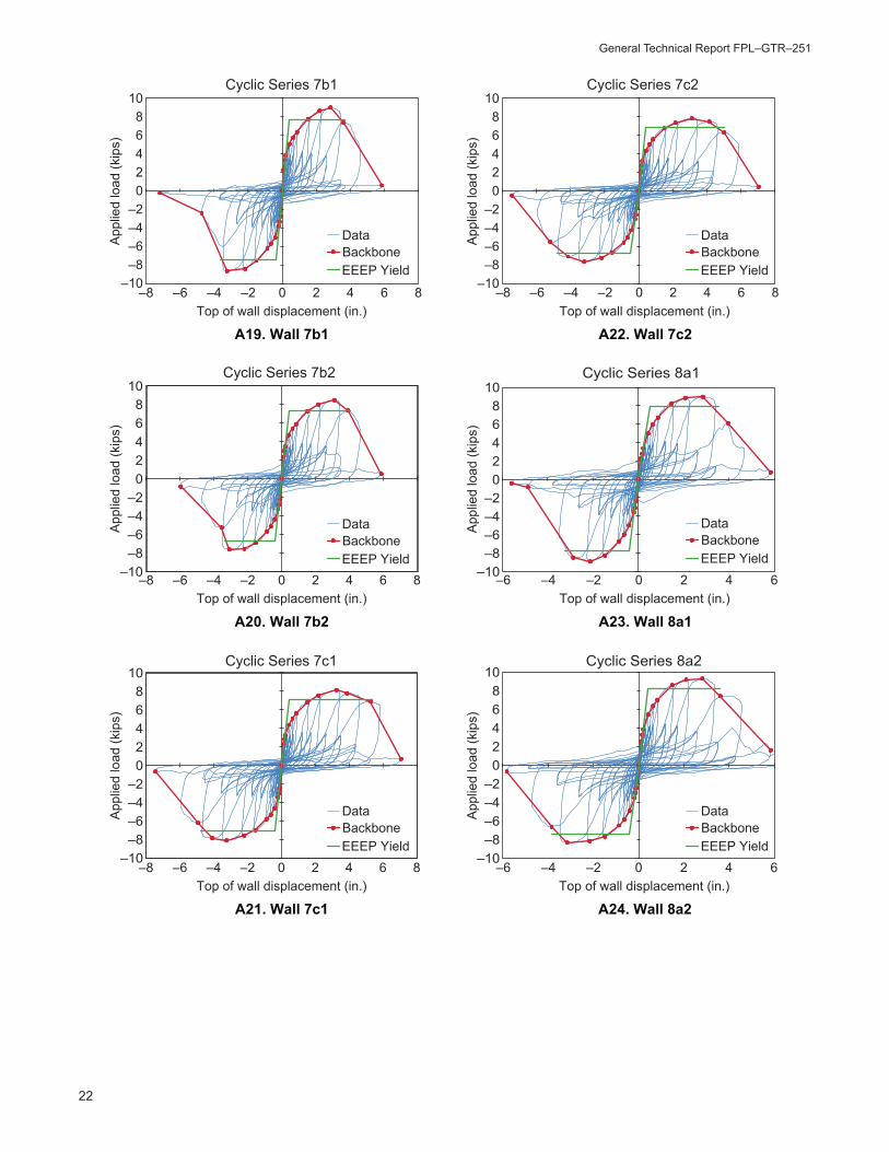
Number of Panel JointsFigure 17 shows the backbone curves from three replica-tions of the basic wall configuration, Wall 2a, and two replications of Walls 7a, 7b, and 7c with no panel joint, two panel joints, and three panel joints, respectively. The hys-teresis loops for these cyclic data are provided in Appendix A2–A4 and A17–A22.
The mean ultimate load value for Wall 2a was 1,188 plf based on the mean positive loads and the absolute value of
-–15
-–10
-–5
0
5
10
15
–6 –4 –2 0 2 4 6
Top of wall displacement (in.)
App
lied
load
(kip
s)2a12a22a35a15a2
-–15
-–10
-–5
0
5
10
15
–6 –4 –2 0 2 4 6
Top of wall displacement (in.)
App
lied
load
(kip
s)
2a12a22a36a16a2

Lateral Load Performance of SIP Walls with Full Bearing
15
Figure 17. Backbone curves comparing the walls with one joint (Wall 2a), zero joints (Wall 7a), two joints (Wall 7b), and three joints (Wall 7c).
the mean negative peak loads. The mean ultimate load val-ues for Walls 7a, 7b, and 7c were 1,314 plf, 1,052 plf, and 986 plf, respectively. Some observations can be noted from Figure 17. The points where the maximum load was ob-served is clearly a function of the number of joints. This is expected based on the performance of light-frame walls. In terms of the ultimate loads, zero panel joints (Wall 7a) result in an increase in the ultimate load of around 10%. Increas-ing the number of joints from 1 to 2 (Wall 7b) and from 1 to 3 (Wall 7c) resulted in the ultimate load reduction of 11% and 17%, respectively. All these comparisons are made with the basic wall configuration, Wall 2a.
When considering the ICC-ES AC04 cyclic analysis, as sum-marized in Table 2, a few observations are noted: The cyclic performance parameters were similar in terms of the ductil-ity capacity. As expected, the drift capacity was significantly affected by the number of splines. The wall without vertical joints, Wall 7a, had the lowest drift capacity, 0.021H, among all walls tested. The drift capacity was 0.029H, 0.039H and 0.052H, for 1, 2, and 3 vertical joints, respectively. This in-dicates the importance of panel joints in SIP walls to ensure drift capacity under seismic loading.
Figure 18. Backbone curves comparing SIPs of 4-1/2-in. thickness (Wall 2a) and 6-1/2-in. thickness (Wall 8a).
-–15
-–10
-–5
0
5
10
15
–6 –4 –2 0 2 4 6
Top of wall displacement (in.)
App
lied
load
(kip
s)
2a12a22a38a18a2
–15
–10
–5
0
5
10
15
–8 –6 –4 –2 0 2 4 86
Top of wall displacement (in.)
App
lied
load
(kip
s)2a12a22a37a17a27b17b27c17c2

General Technical Report FPL–GTR–251
16
SIP ThicknessFigure 18 shows the backbone curves from three replica-tions of the basic wall configuration, Wall 2a, and two replications of Wall 8a with a SIP thickness of 6-1/2 in. The hysteresis loops for these cyclic data are provided in Appendix A2–A4, A23, and A24.
The mean ultimate load value for Wall 2a was 1,188 plf based on the mean positive loads and the absolute value of the mean negative peak loads. The mean ultimate load value for Wall 8a was 1,110 plf. In terms of ultimate loads, the 6-1/2-in. thick SIP walls (Wall 8a) were about 7% lower than the 4-1/2-in. thick walls (Wall 2a). However, the magnitude of the difference in the ultimate load (78 plf) is within the testing and material variabilities. Based on these results, SIPs with these wall thicknesses are considered to result in very similar ultimate load performance.
When considering the ICC-ES AC04 cyclic analysis, as summarized in Table 2, all cyclic parameters met the AC04 cyclic criteria. However, the 6-1/2-in. thick walls did have a relatively high drift capacity of 0.037H, compared with 0.029H for the 4-1/2-in. thick walls. From the backbone curves shown in Figure 18, the lateral load performance between these two SIP wall thicknesses is quite compatible.
Orientation of OSB FacersFigure 19 shows the backbone curves from three replica-tions of the basic wall configuration, Wall 2a, and two repli-cations of Wall 9a with cross-oriented OSB facers. Included in Figure 19 is the “trial” wall test, which was also based on cross-oriented OSB. The hysteresis loops for these cyclic data are provided in Appendix A1–A4, A25, and A26.
The mean ultimate load value for Wall 2a was 1,188 plf based on the mean positive loads and the absolute value of the mean negative peak loads. The mean ultimate load value for Wall 9a was 1,097 plf and the mean value of the trial was 1,034 plf. The cross-oriented OSB facers resulted in an 8% decrease in ultimate load. If the “trial” wall is included, the decrease in ultimate load for cross-oriented OSB facer is about 10%. Given the testing and material variabilities, the effect of OSB facer orientation on ultimate load can be considered as marginal.
When considering the ICC-ES AC04 cyclic analysis, as summarized in Table 2, the cyclic performance parameters for both OSB facer orientations were similar. However, the drift capacity of 0.026H for the cross-oriented OSB facers was slightly lower than the AC04 criteria. This was not ex-pected, because OSB orientation is known to not significant-ly affect the lateral load performance of light-frame walls.
Bottom Plate Washer GeometryFigure 20 shows the backbone curves from the SIPs with cross-oriented OSB facers and installed with square (0.229- by 3- by 3-in.) washers (Wall 9a), large (0.229-in. by 3-in.-diameter) round washers (Wall 2b), and standard (0.134-in. by 1.75-in.-diameter) washers (Wall 2c) for the 5/8-in.-di-ameter anchor bolts. Included in Figure 20 is the “trial” wall test, which was also based on cross-oriented OSB facers. The hysteresis loops for these cyclic data are provided in Appendix A1, A5, A6, A25, and A26.
The mean ultimate load value for Wall 9a was 1,097 plf based on the mean positive loads and the absolute value of the mean negative peak loads. The mean ultimate load values for Walls 2b and 2c were both 965 plf, and the mean
Figure 19. Backbone curves comparing facer orientations between vertical (Wall 2a) and horizontal (Wall 9a).
-–15
-–10
-–5
0
5
10
15
–6 –4 –2 0 2 4 6
Top of wall displacement (in.)
App
lied
load
(kip
s)2a12a22a39a19a2Trial

Lateral Load Performance of SIP Walls with Full Bearing
17
Figure 20. Backbone curves comparing square washers (Wall 9a) and round washers (Walls 2b and 2c).
value for the “trial” wall was 1,034 plf. Based on the small sample sizes, using the round washers (Walls 2b and 2c) reduced the ultimate load by 13%, as compared with square washers (Wall 9a). There is no difference in ultimate load between the large and standard cut round washers. However, because the failure modes were often associated with the top plate, but virtually never associated with the bottom plate, the difference in ultimate load between square and round washers is recommended to be further studied.
When considering the ICC-ES AC04 cyclic analysis, the cyclic performance parameters were similar. The walls with round washers had a higher drift capacity. However, it is difficult to be certain if these differences are significant and if the results are repeatable due to the lack of replicates for the wall with the large round washer and the wall with the standard cut round washer.
Summary and ConclusionsThis report covers the testing of 29 full-size SIP walls of various configurations. Table 2 summarizes the cyclic performance parameters based on the assumed allowable design values published in ICC-ES ESR-1539. In general, the cyclic performance parameters for all walls tested in this study met the over-strength and ductility capacities of ICC-ES AC04, although some walls had drift capacities slightly lower than the AC04 criterion. The one exception was the wall without any vertical joints, which showed a signifi-cantly low drift capacity of 0.021H.
The findings for the different variables studied can be sum-marized as follows:
1. Test protocol (monotonic and cyclic)—Testing based on ASTM E72 and ASTM E2126 resulted in similar ultimate
loads. Testing based on ASTM E564 and ASTM E2126 resulted in similar deflection profiles, but the ultimate load from monotonic (ASTM E564) tests was ap-proximately 12% lower than that from the cyclic (ASTM E2126) tests. There is not enough evidence to conclude that ASTM E564 will result in a significantly lower ulti-mate load than the other test methods.
2. Nail size for panel connection (8d Box and 8d Com-mon)—Data showed that there was no practical difference in ultimate load between SIP walls constructed with these two nail sizes.
3. Nail spacing (6, 4, and 3 in.)—Data showed that a de-crease in nail spacing from 6 to 4 in. and from 6 to 3 in. on center resulted in ultimate load increases of 27% and 58%, respectively.
4. Wall bearing type (wood and rigid steel bearing)—Data showed that when SIPs bear on steel, as compared to SPF bottom plates, ultimate load is reduced by approximately 15%. However, this decrease in ultimate load could have been affected by the increase in spline nailing spacing from 6 in. to 12 in. for improved wall ductility. In this case, the effect of bearing plate types on cyclic perfor-mance parameters was insignificant.
5. Spline type (block spline and two 2× lumber spline)— Data showed that the difference in ultimate load is insig-nificant (less than 5%).
6. Number of panel joints (no joint, one, two, and three joints)—Data showed that the number of panel joints and the aspect ratio of the individual SIP segments clearly had an effect on the cyclic performance. The more joints, the higher the ductility capacity of the SIP walls. Compared with one panel joint, zero joint resulted in an increase of
–15
–10
–5
0
5
10
15
–6 –4 –2 0 2 4 6
Top of wall displacement (in.)
App
lied
load
(kip
s)2b12c19a19a2Trial

General Technical Report FPL–GTR–251
18
around 10% in ultimate load, whereas two and three joints resulted in a reduction in ultimate load of 11% and 17%, respectively.
7. SIP thickness (4-1/2 and 6-1/2 in.)—Data showed that the ultimate load is similar between SIP wall thicknesses of 4-1/2 and 6-1/2 in. (less than 7% difference).
8. Orientation of OSB facers (strength axis horizontal and vertical)—Data showed that cross-oriented (horizontally oriented) facers resulted in a marginal (approximately 10%) reduction in ultimate load, as compared with verti-cally oriented OSB facers.
9. Bottom plate washer geometry (square and round)—Data showed no difference between large and standard round washers. However, the square washers showed a 13% higher ultimate load. However, because the failure modes were often associated with the top plate and virtually never associated with the bottom plate, the difference in ultimate load between square and round washers is rec-ommended to be further studied.
Literature CitedANSI/APA. 2013. Standard for performance-rated struc-tural insulated panels in wall application, ANSI/APA PRS 610.1-2013. Tacoma, WA: APA – The Engineered Wood Association.
APA. 2010. Racking tests of structural insulated panels (SIPs) with various bearing conditions for the Structural Insulated Panel Association, Gig Harbor, Washington. APA Report T2010P-17. Tacoma, WA: APA – The Engineered Wood Association.
ASCE. 2010. Minimum design loads for buildings and other structures. ASCE-7. Reston, VA: American Society of Civil Engineers.
ASTM. 2011. Standard test methods for cyclic (reversed) load test for shear resistance of vertical elements of the lateral force resisting systems for buildings. ASTM E2126. West Conshohocken, PA: ASTM International.
ASTM. 2012. Standard practice for static load tests for shear resistance of framed walls for buildings. ASTM E564. West Conshohocken, PA: ASTM International.
ASTM. 2015a. Standard practice for demonstrating equiva-lent in-plane lateral seismic performance to wood-frame shear walls sheathed with wood structural panels. ASTM D7989. West Conshohocken, PA: ASTM International.
ASTM. 2015b. Standard test methods of conducting strength tests of panels for building construction. ASTM E72. West Conshohocken, PA: ASTM International.
AWC. 2015. National design specification for wood con-struction. Leesburg, VA: American Wood Council.
ICC-ES. 2015. Acceptance criteria for sandwich panels—AC04. Brea, CA: ICC Evaluation Service, LLC.
ICC-ES. 2016. Power-driven staples and nails—Internation-al Staple, Nail and Tool Association, ESR-1539. Brea, CA: ICC Evaluation Service, LLC.
Yeh, B.; Skaggs, T.; Wang, X.; Williamson, T. 2016. Lateral load performance of SIP walls with full bearing. APA Report. Tacoma, WA: APA – The Engineered Wood Association.

Lateral Load Performance of SIP Walls with Full Bearing
19
Appendix—Hysteresis Plots of the SIP Walls Subjected to CUREE Loading Protocol
A1. “Trial” wall A4. Wall 2a3
–10–8–6–4–2
02468
10
–5 –4 –3 –2 –1 0 1 2 3 4 5
App
lied
load
(kip
s)
Top of wall displacement (in.)
A2. Wall 2a1Top of wall displacement (in.)
–5 –4 –3 –2 –1 0 1 2 3 4 5
A3. Wall 2a2Top of wall displacement (in.)
–5 –4 –3 –2 –1 0 1 2 3 4 5
–5 –4 –3 –2 –1 0 1 2 3 4 5
Trial
DataBackboneEEEP Yield
DataBackboneEEEP Yield
DataBackboneEEEP Yield
DataBackboneEEEP Yield
DataBackboneEEEP Yield
DataBackboneEEEP Yield
–15
–10
–5
0
5
10
15
–15
–10
–5
0
5
10
15
Cyclic Series 2a1
Cyclic Series 2a2
–10
–5
0
5
10
15
–5 –4 –3 –2 –1 0 1 2 3 4 5
Appl
ied
load
(kip
s)
App
lied
load
(kip
s)
Appl
ied
load
(kip
s)
App
lied
load
(kip
s)
Appl
ied
load
(kip
s)
Top of wall displacement (in.)
A5. Wall 2b1Top of wall displacement (in.)
–5 –4 –3 –2 –1 0 1 2 3 4 5
A6. Wall 2c1Top of wall displacement (in.)
Cyclic Series 2a3
–10–8–6–4–2
02468
10
–10–8–6–4–2
02468
10
Cyclic Series 2b1
Cyclic Series 2c1

General Technical Report FPL–GTR–251
20
A7. Wall 3a1 A10. Wall 4a2
–15
–10
–5
0
5
10
15
–5 –4 –3 –2 –1 0 1 2 3 4 5
App
lied
load
(kip
s)
Top of wall displacement (in.)
A8. Wall 3a2Top of wall displacement (in.)
–5 –4 –3 –2 –1 0 1 2 3 4 5
A9. Wall 4a1Top of wall displacement (in.)
–5 –4 –3 –2 –1 0 1 2 3 4 5
–5 –4 –3 –2 –1 0 1 2 3 4 5
Cyclic series 3a1
–10–8–6–4–2
0
642
810
–20
–15
–10
–5
0
5
10
20
15
Cyclic Series 3a2
Cyclic Series 4a1
–20
–15
–10
–5
0
5
15
10
20
–5 –4 –3 –2 –1 0 1 2 3 4 5
Appl
ied
load
(kip
s)
App
lied
load
(kip
s)
Appl
ied
load
(kip
s)
App
lied
load
(kip
s)
Appl
ied
load
(kip
s)
Top of wall displacement (in.)
A11. Wall 4b1Top of wall displacement (in.)
–5 –4 –3 –2 –1 0 1 2 3 4 5
A12. Wall 4b2Top of wall displacement (in.)
Cyclic Series 4a2
–15
–10
–5
0
5
10
15
–15
–10
–5
0
5
10
15
Cyclic Series 4b1
Cyclic Series 4b2
DataBackboneEEEP Yield
DataBackboneEEEP Yield
DataBackboneEEEP Yield
DataBackboneEEEP Yield
DataBackboneEEEP Yield
DataBackboneEEEP Yield

Lateral Load Performance of SIP Walls with Full Bearing
21
A13. Wall 5a1 A16. Wall 6a2
–10–8–6–4–2
02468
10
–5 –4 –3 –2 –1 0 1 2 3 4 5
App
lied
load
(kip
s)
Top of wall displacement (in.)
A14. Wall 5a2Top of wall displacement (in.)
–5 –4 –3 –2 –1 0 1 2 3 4 5
A15. Wall 6a1Top of wall displacement (in.)
–5 –4 –3 –2 –1 0 1 2 3 4 5
–8 –6 –4 –2 0 2 4 6 8
Cyclic series 5a1
DataBackboneEEEP Yield
DataBackboneEEEP Yield
DataBackboneEEEP Yield
DataBackboneEEEP Yield
DataBackboneEEEP Yield
DataBackboneEEEP Yield
–10–8–6–4–20
642
810
–15
–10
–5
0
5
10
15
Cyclic Series 5a2
Cyclic Series 6a1
–10–8–6–4–2
02
64
810
–5 –4 –3 –2 –1 0 1 2 3 4 5
Appl
ied
load
(kip
s)
App
lied
load
(kip
s)
Appl
ied
load
(kip
s)
App
lied
load
(kip
s)
Appl
ied
load
(kip
s)
Top of wall displacement (in.)
A17. Wall 7a1Top of wall displacement (in.)
–8 –6 –4 –2 0 2 4 6 8
A18. Wall 7a2Top of wall displacement (in.)
Cyclic Series 6a2
–15
–10
–5
0
5
10
15
–15
–10
–5
0
5
10
15
Cyclic Series 7a1
Cyclic Series 7a2
General Technical Report FPL–GTR–251
22
A19. Wall 7b1 A22. Wall 7c2
–10–8–6–4–2
02468
10
–10–8–6–4–2
02468
10
–8 –6 –4 –2 0 2 4 6 8
–8 –6 –4 –2 0 2 4 6 8
–8 –6 –4 –2 0 2 4 6 8
App
lied
load
(kip
s)
App
lied
load
(kip
s)
Top of wall displacement (in.)
A20. Wall 7b2Top of wall displacement (in.)
A21. Wall 7c1Top of wall displacement (in.)
–6 –4 –2 0 2 4 6
–6 –4 –2 0 2 4 6
Cyclic Series 7b1
DataBackboneEEEP Yield
DataBackboneEEEP Yield
DataBackboneEEEP Yield
DataBackboneEEEP Yield
DataBackboneEEEP Yield
DataBackboneEEEP Yield
Cyclic Series 7b2
Cyclic Series 7c1
–8 –6 –4 –2 0 2 4 6 8
App
lied
load
(kip
s)
Appl
ied
load
(kip
s)
App
lied
load
(kip
s)
Appl
ied
load
(kip
s)
Top of wall displacement (in.)
A23. Wall 8a1Top of wall displacement (in.)
A24. Wall 8a2Top of wall displacement (in.)
Cyclic Series 7c2
–10–8–6–4–2
02468
10
–10–8–6–4–2
02468
10
–10–8–6–4–2
02468
10
–10–8–6–4–2
02468
10
Cyclic Series 8a1
Cyclic Series 8a2

Lateral Load Performance of SIP Walls with Full Bearing
23
A25. Wall 9a1 A26. Wall 9a2
–10–8–6–4–2
02468
10
–10–8–6–4–2
02468
10
–6 –4 –2 0 2 4 6
App
lied
load
(kip
s)
App
lied
load
(kip
s)
Top of wall displacement (in.)
Cyclic Series 9a1
–6 –4 –2 0 2 4 6Top of wall displacement (in.)
Cyclic Series 9a2
DataBackboneEEEP Yield
DataBackboneEEEP Yield