Embed Size (px)
Citation preview

1
DCS GUIDEP-51D MUSTANG
By ChuckLAST UPDATED: 06/02/2018
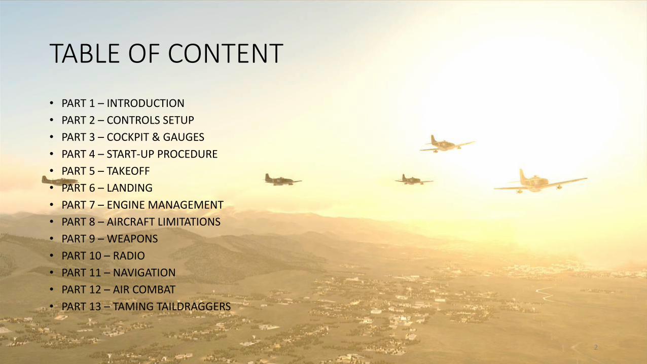
TABLE OF CONTENT
• PART 1 – INTRODUCTION
• PART 2 – CONTROLS SETUP
• PART 3 – COCKPIT & GAUGES
• PART 4 – START-UP PROCEDURE
• PART 5 – TAKEOFF
• PART 6 – LANDING
• PART 7 – ENGINE MANAGEMENT
• PART 8 – AIRCRAFT LIMITATIONS
• PART 9 – WEAPONS
• PART 10 – RADIO
• PART 11 – NAVIGATION
• PART 12 – AIR COMBAT
• PART 13 – TAMING TAILDRAGGERS
2
3
PAR
T 1
–IN
TRO
DU
CTI
ON
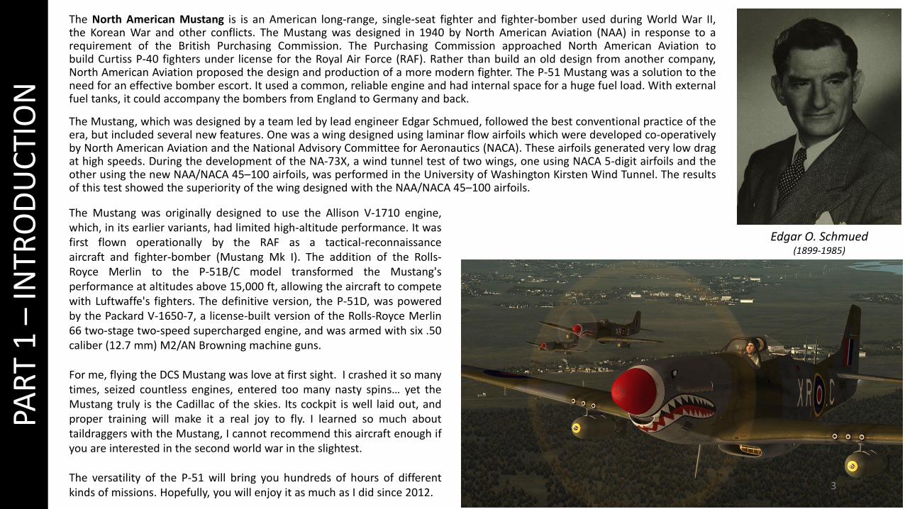
The North American Mustang is is an American long-range, single-seat fighter and fighter-bomber used during World War II,the Korean War and other conflicts. The Mustang was designed in 1940 by North American Aviation (NAA) in response to arequirement of the British Purchasing Commission. The Purchasing Commission approached North American Aviation tobuild Curtiss P-40 fighters under license for the Royal Air Force (RAF). Rather than build an old design from another company,North American Aviation proposed the design and production of a more modern fighter. The P-51 Mustang was a solution to theneed for an effective bomber escort. It used a common, reliable engine and had internal space for a huge fuel load. With externalfuel tanks, it could accompany the bombers from England to Germany and back.
The Mustang, which was designed by a team led by lead engineer Edgar Schmued, followed the best conventional practice of theera, but included several new features. One was a wing designed using laminar flow airfoils which were developed co-operativelyby North American Aviation and the National Advisory Committee for Aeronautics (NACA). These airfoils generated very low dragat high speeds. During the development of the NA-73X, a wind tunnel test of two wings, one using NACA 5-digit airfoils and theother using the new NAA/NACA 45–100 airfoils, was performed in the University of Washington Kirsten Wind Tunnel. The resultsof this test showed the superiority of the wing designed with the NAA/NACA 45–100 airfoils.
Edgar O. Schmued(1899-1985)
The Mustang was originally designed to use the Allison V-1710 engine,which, in its earlier variants, had limited high-altitude performance. It wasfirst flown operationally by the RAF as a tactical-reconnaissanceaircraft and fighter-bomber (Mustang Mk I). The addition of the Rolls-Royce Merlin to the P-51B/C model transformed the Mustang'sperformance at altitudes above 15,000 ft, allowing the aircraft to competewith Luftwaffe's fighters. The definitive version, the P-51D, was poweredby the Packard V-1650-7, a license-built version of the Rolls-Royce Merlin66 two-stage two-speed supercharged engine, and was armed with six .50caliber (12.7 mm) M2/AN Browning machine guns.
For me, flying the DCS Mustang was love at first sight. I crashed it so manytimes, seized countless engines, entered too many nasty spins… yet theMustang truly is the Cadillac of the skies. Its cockpit is well laid out, andproper training will make it a real joy to fly. I learned so much abouttaildraggers with the Mustang, I cannot recommend this aircraft enough ifyou are interested in the second world war in the slightest.
The versatility of the P-51 will bring you hundreds of hours of differentkinds of missions. Hopefully, you will enjoy it as much as I did since 2012.

4
PAR
T 2
–C
ON
TRO
LS S
ETU
PCONTROL FUNCTION
COMM PUSH TO TALK ALLOWS YOU TO USE RADIO MENU WHILE FLYING
FLAPS DOWN OPENS UP YOUR FLAPS 10 DEGREES (FLAP SETTINGS ARE 0, 10, 20, 30, 40 & 50 deg)
FLAPS UP RETRACTS YOUR FLAPS 10 DEGREES (FLAP SETTINGS ARE 0, 10, 20, 30, 40 & 50 deg)
GUN FIRE FIRES YOUR .50 CAL GUNS
LANDING GEAR UP/DOWN RAISES OR DEPLOYS YOUR LANDING GEAR
RADIATOR COOLANT OPEN
THESE RADIATOR CONTROLS ARE USEFUL IN SITUATIONS WHERE YOU NEED TO COOL YOUR ENGINE QUICKLY. OTHERWISE, YOU CAN FLY USING THE AUTO MODE FOR RADIATORS. SEE ENGINE MANAGEMENT SECTION.
RADIATOR COOLANT CLOSE
RADIATOR OIL OPEN
RADIATOR OIL CLOSE
STARTER STARTER SWITCH. MAP IT TO SOMETHING YOU CAN HOLD OR TOGGLE.
TRIM ELEVATOR DOWN/UP ELEVATOR TRIM CONTROL
TRIM RUDDER LEFT/RIGHT RUDDER TRIM CONTROL
WAR EMERGENCY POWER WEP (WAR EMERGENCY POWER). USE WITH CAUTION.
WEAPON RELEASE ALLOWS YOU TO RELEASE YOUR BOMBS, ROCKETS AND DROP TANKS.
ZOOM IN SLOW ALLOWS YOU TO ZOOM IN
ZOOM OUT SLOW ALLOWS YOU TO ZOOM OUT
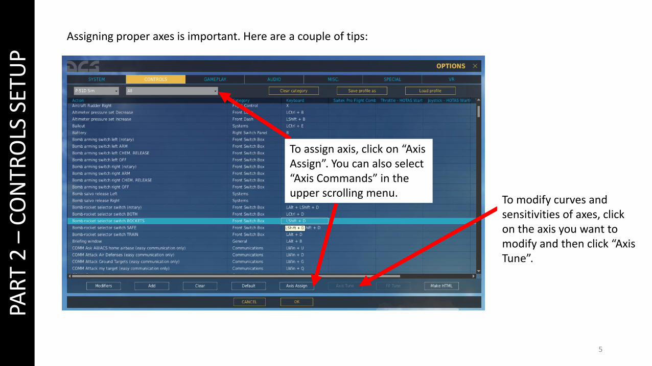
Assigning proper axes is important. Here are a couple of tips:
5
To modify curves and sensitivities of axes, click on the axis you want to modify and then click “Axis Tune”.
PAR
T 2
–C
ON
TRO
LS S
ETU
P
To assign axis, click on “Axis Assign”. You can also select “Axis Commands” in the upper scrolling menu.
6
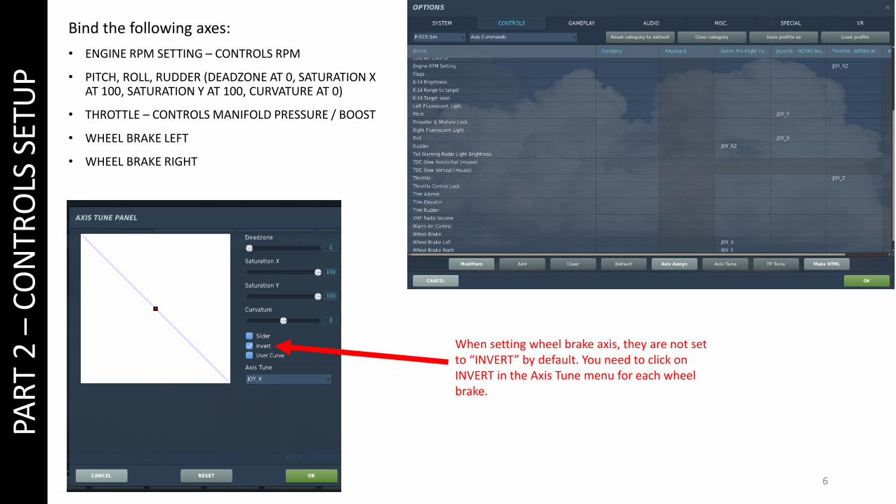
When setting wheel brake axis, they are not set to “INVERT” by default. You need to click on INVERT in the Axis Tune menu for each wheel brake.
PAR
T 2
–C
ON
TRO
LS S
ETU
PBind the following axes:
• ENGINE RPM SETTING – CONTROLS RPM
• PITCH, ROLL, RUDDER (DEADZONE AT 0, SATURATION X AT 100, SATURATION Y AT 100, CURVATURE AT 0)
• THROTTLE – CONTROLS MANIFOLD PRESSURE / BOOST
• WHEEL BRAKE LEFT
• WHEEL BRAKE RIGHT
7
PAR
T 3
–C
OC
KP
IT A
ND
GA
UG
ES
8
PAR
T 3
–C
OC
KP
IT A
ND
GA
UG
ES
9
PAR
T 3
–C
OC
KP
IT A
ND
GA
UG
ES
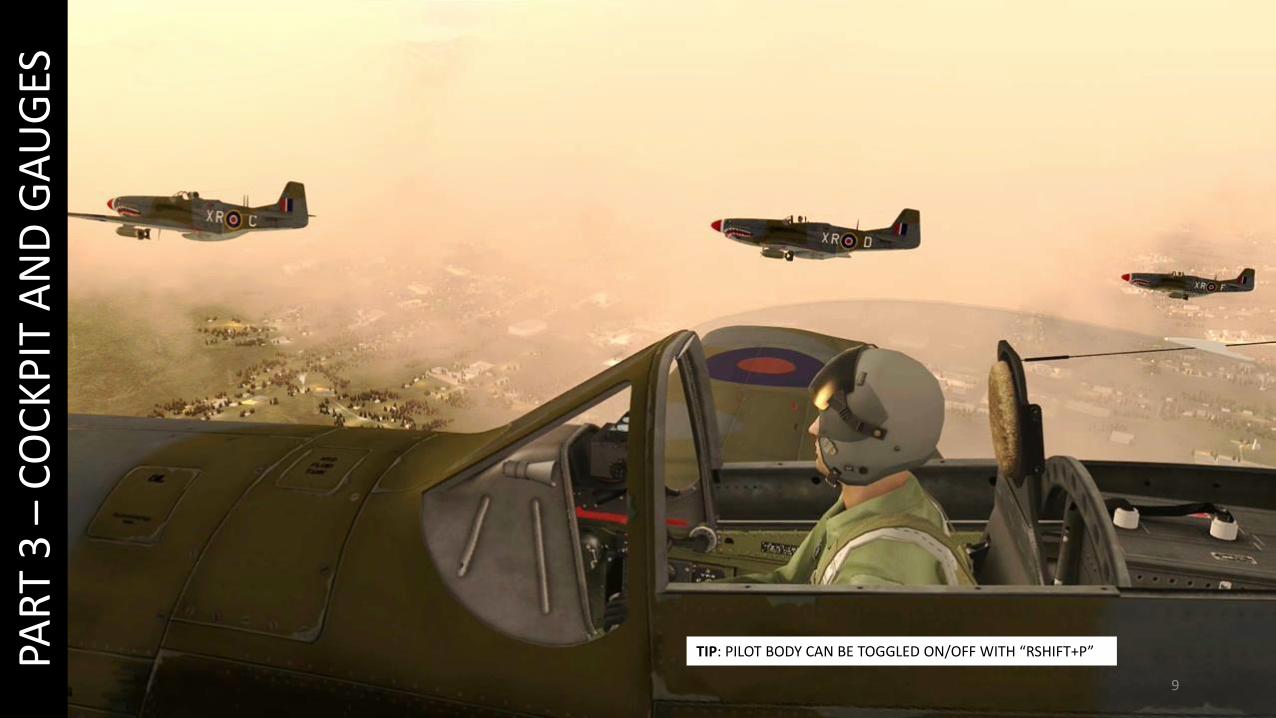
TIP: PILOT BODY CAN BE TOGGLED ON/OFF WITH “RSHIFT+P”
10
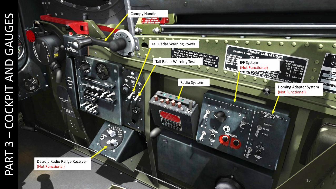
Radio System
IFF System(Not Functional)
Homing Adapter System(Not Functional)
Canopy Handle
Tail Radar Warning Power
Tail Radar Warning Test
PAR
T 3
–C
OC
KP
IT A
ND
GA
UG
ES
Detrola Radio Range Receiver(Not Functional)

11
PAR
T 3
–C
OC
KP
IT A
ND
GA
UG
ESRight Fluorescent Tuner
Circuit Protectors Panel(Push to Open)
Ampmeter
Generator Disconnect
Battery Disconnect
Gun Heater
Red Recognition Light
Green Recognition Light
Amber Recognition Light
Pitot Heater
Wing Navigation Lights
Tail Position Lights
12
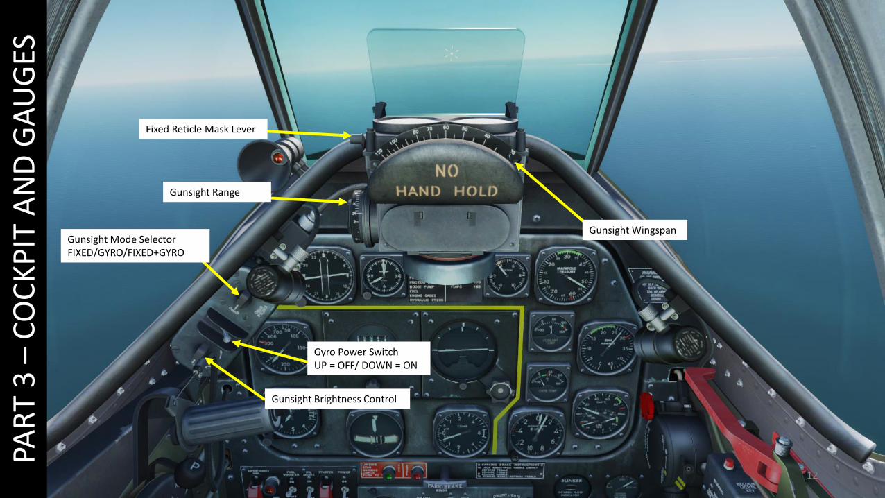
Fixed Reticle Mask Lever
Gunsight Wingspan
Gunsight Range
Gunsight Mode SelectorFIXED/GYRO/FIXED+GYRO
Gyro Power SwitchUP = OFF/ DOWN = ON
Gunsight Brightness Control
PAR
T 3
–C
OC
KP
IT A
ND
GA
UG
ES

13
Altitude Indicator (x1000ft)
Airspeed Indicator (mph)
Directional Gyro
Magnetic Compass
Turn & Bank Indicator
Manifold Pressure (inches HG)
Tachometer (RPM)
Vertical Speed Indicator (x1000ft/min)
Oil Temperature (deg C)
Artificial Horizon
Coolant Temperature (deg C)
Clock
Suction Pressure Gauge (inches HG)
Carburettor Temperature (deg C)
Accelerometer (G)
PAR
T 3
–C
OC
KP
IT A
ND
GA
UG
ES
Fuel Pressure (PSI)
Oil Pressure(PSI)
14
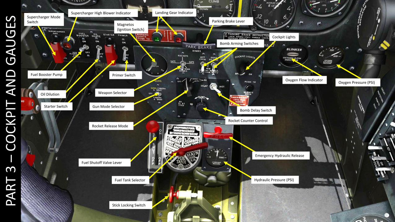
Parking Brake Lever
Weapon Selector
Fuel Booster Pump
Oil Dilution
Starter Switch
Primer Switch
Supercharger Mode Switch
Supercharger High Blower Indicator
Magnetos (Ignition Switch)
Gun Mode Selector
Fuel Shutoff Valve Lever
Fuel Tank Selector Hydraulic Pressure (PSI)
Emergency Hydraulic Release
Stick Locking Switch
Rocket Counter Control
Rocket Release Mode
Bomb Delay Switch
Bomb Arming Switches
Cockpit Lights
Oxygen Flow IndicatorOxygen Pressure (PSI)
PAR
T 3
–C
OC
KP
IT A
ND
GA
UG
ESLanding Gear Indicator
15
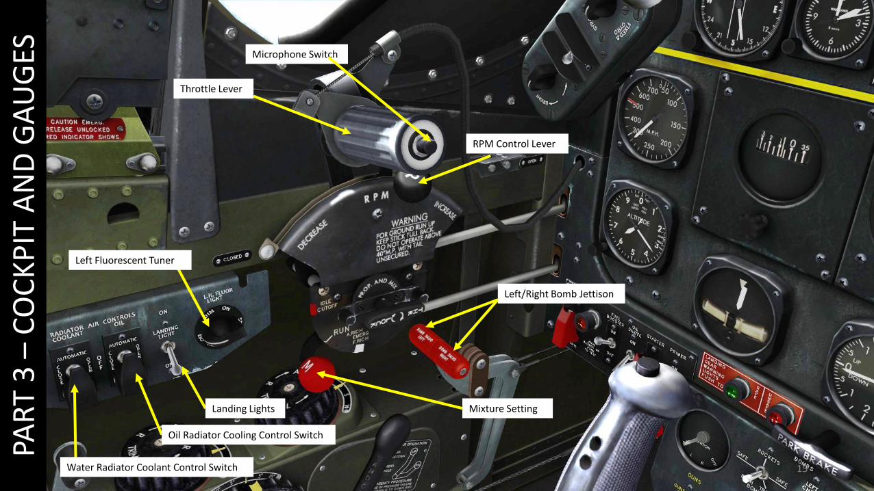
Throttle Lever
Microphone Switch
RPM Control Lever
Left/Right Bomb Jettison
Mixture Setting
Left Fluorescent Tuner
Landing Lights
Water Radiator Coolant Control Switch
Oil Radiator Cooling Control Switch
PAR
T 3
–C
OC
KP
IT A
ND
GA
UG
ES

16
Flaps Control
Flaps Setting Indicator (degrees)
Carburettor Cold Air Control Lever
Carburettor Warm Air Control Lever
Rudder Trim Wheel
Aileron Trim Wheel
Elevator Trim WheelLanding Gear Lever
PAR
T 3
–C
OC
KP
IT A
ND
GA
UG
ES
17
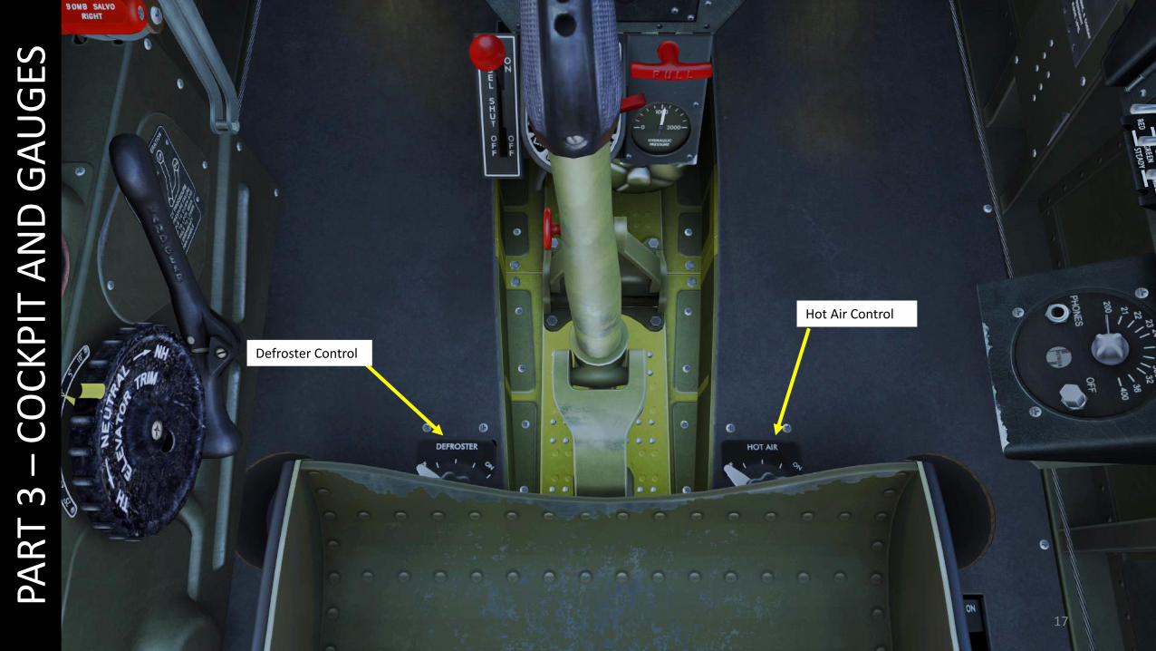
Defroster Control
Hot Air Control
PAR
T 3
–C
OC
KP
IT A
ND
GA
UG
ES
18
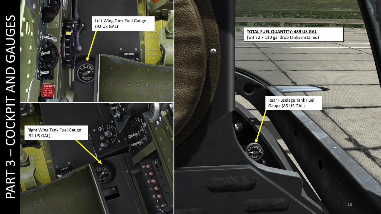
Left Wing Tank Fuel Gauge (92 US GAL)
Right Wing Tank Fuel Gauge (92 US GAL)
Rear Fuselage Tank Fuel Gauge (85 US GAL)
PAR
T 3
–C
OC
KP
IT A
ND
GA
UG
ES
TOTAL FUEL QUANTITY: 489 US GAL(with 2 x 110 gal drop tanks installed)

19
PAR
T 3
–C
OC
KP
IT A
ND
GA
UG
ESMirror

20
PAR
T 3
–C
OC
KP
IT A
ND
GA
UG
ES
8 x HVAR 5-in. Rockets2 x M64 500 lbs Bombs
6 x 0.50 cal Browning M2 Machineguns
21
PAR
T 3
–C
OC
KP
IT A
ND
GA
UG
ES
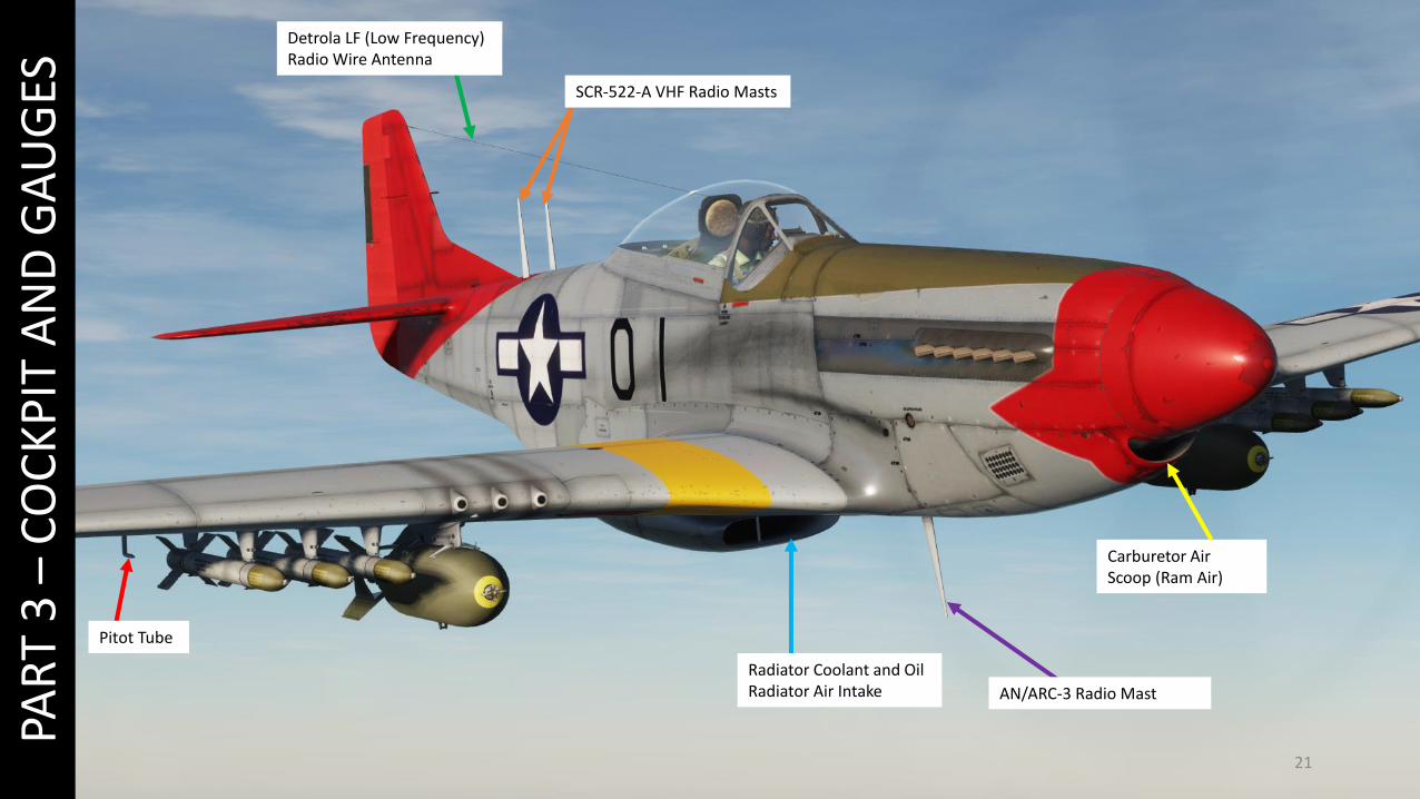
Radiator Coolant and Oil Radiator Air Intake
Pitot Tube
Carburetor Air Scoop (Ram Air)
SCR-522-A VHF Radio Masts
Detrola LF (Low Frequency) Radio Wire Antenna
AN/ARC-3 Radio Mast

22
PAR
T 3
–C
OC
KP
IT A
ND
GA
UG
ES
Oil Radiator Outlet
Aftercooler & Engine Coolant Radiator Outlet

23
PAR
T 3
–C
OC
KP
IT A
ND
GA
UG
ES
Elevator Trim Tabs
Rudder Trim Tab
AN/APS-13 Rear Warning Radar Antenna

24
PAR
T 3
–C
OC
KP
IT A
ND
GA
UG
ES
414999: Aircraft Serial NumberHO: USAAF Squadron
Code. “HO” belongs to 485th Fighter Squadron.
In World War 2, the United States Army Air Forces used aircraft markingsas identification codes. For instance, “HO-W” means that the Aircraft Wbelongs to the 485th Fighter Squadron (HO). You can set up your aircraftmarkings in the Mission Editor.
W: Aircraft Identification Letter
25
PAR
T 4
–ST
AR
T-U
P
1
3
2
4
5
6
7
8
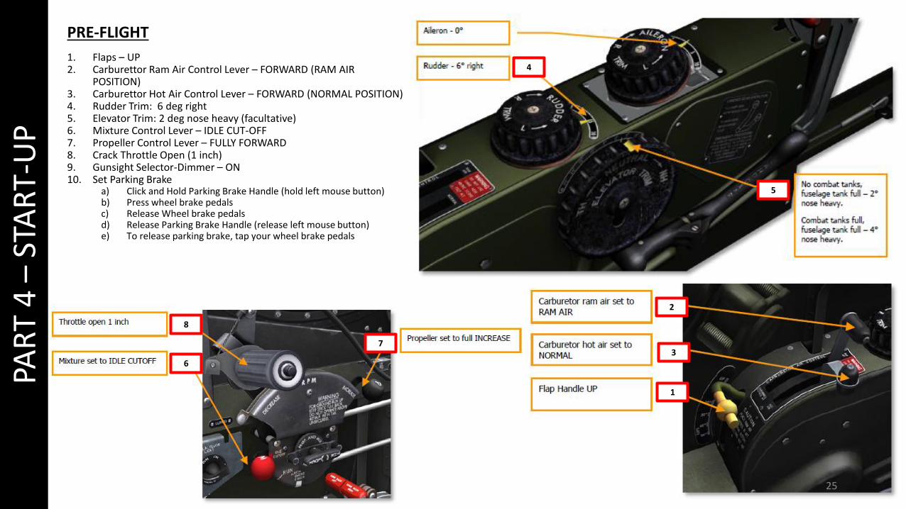
PRE-FLIGHT
1. Flaps – UP 2. Carburettor Ram Air Control Lever – FORWARD (RAM AIR
POSITION)3. Carburettor Hot Air Control Lever – FORWARD (NORMAL POSITION) 4. Rudder Trim: 6 deg right5. Elevator Trim: 2 deg nose heavy (facultative)6. Mixture Control Lever – IDLE CUT-OFF7. Propeller Control Lever – FULLY FORWARD8. Crack Throttle Open (1 inch)9. Gunsight Selector-Dimmer – ON 10. Set Parking Brake
a) Click and Hold Parking Brake Handle (hold left mouse button)b) Press wheel brake pedals c) Release Wheel brake pedalsd) Release Parking Brake Handle (release left mouse button)e) To release parking brake, tap your wheel brake pedals
26
PAR
T 4
–ST
AR
T-U
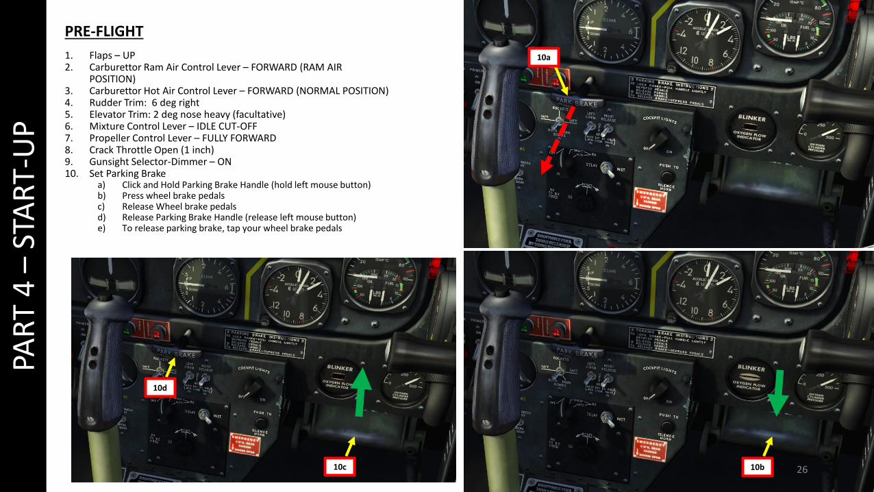
PPRE-FLIGHT
1. Flaps – UP 2. Carburettor Ram Air Control Lever – FORWARD (RAM AIR
POSITION)3. Carburettor Hot Air Control Lever – FORWARD (NORMAL POSITION) 4. Rudder Trim: 6 deg right5. Elevator Trim: 2 deg nose heavy (facultative)6. Mixture Control Lever – IDLE CUT-OFF7. Propeller Control Lever – FULLY FORWARD8. Crack Throttle Open (1 inch)9. Gunsight Selector-Dimmer – ON 10. Set Parking Brake
a) Click and Hold Parking Brake Handle (hold left mouse button)b) Press wheel brake pedals c) Release Wheel brake pedalsd) Release Parking Brake Handle (release left mouse button)e) To release parking brake, tap your wheel brake pedals
10b10c
10d
10a
27
PAR
T 4
–ST
AR
T-U
P1
2
3
45
6
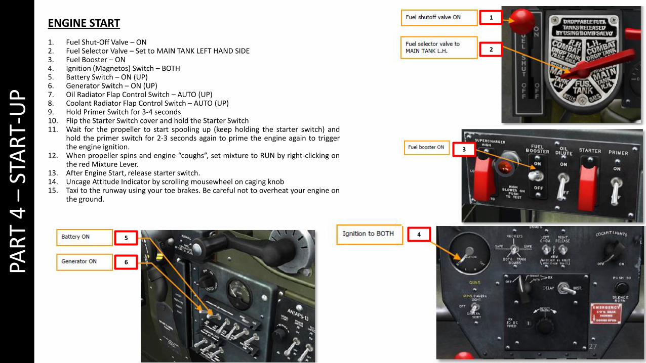
ENGINE START
1. Fuel Shut-Off Valve – ON2. Fuel Selector Valve – Set to MAIN TANK LEFT HAND SIDE3. Fuel Booster – ON4. Ignition (Magnetos) Switch – BOTH5. Battery Switch – ON (UP)6. Generator Switch – ON (UP)7. Oil Radiator Flap Control Switch – AUTO (UP)8. Coolant Radiator Flap Control Switch – AUTO (UP)9. Hold Primer Switch for 3-4 seconds10. Flip the Starter Switch cover and hold the Starter Switch11. Wait for the propeller to start spooling up (keep holding the starter switch) and
hold the primer switch for 2-3 seconds again to prime the engine again to triggerthe engine ignition.
12. When propeller spins and engine “coughs”, set mixture to RUN by right-clicking onthe red Mixture Lever.
13. After Engine Start, release starter switch.14. Uncage Attitude Indicator by scrolling mousewheel on caging knob15. Taxi to the runway using your toe brakes. Be careful not to overheat your engine on
the ground.
28
PAR
T 4
–ST
AR
T-U
P7
8
9
1012
11
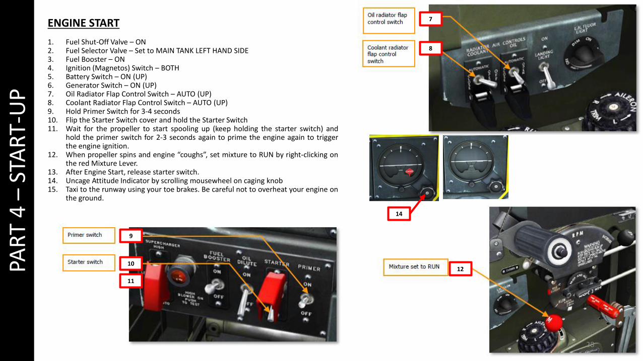
ENGINE START
1. Fuel Shut-Off Valve – ON2. Fuel Selector Valve – Set to MAIN TANK LEFT HAND SIDE3. Fuel Booster – ON4. Ignition (Magnetos) Switch – BOTH5. Battery Switch – ON (UP)6. Generator Switch – ON (UP)7. Oil Radiator Flap Control Switch – AUTO (UP)8. Coolant Radiator Flap Control Switch – AUTO (UP)9. Hold Primer Switch for 3-4 seconds10. Flip the Starter Switch cover and hold the Starter Switch11. Wait for the propeller to start spooling up (keep holding the starter switch) and
hold the primer switch for 2-3 seconds again to prime the engine again to triggerthe engine ignition.
12. When propeller spins and engine “coughs”, set mixture to RUN by right-clicking onthe red Mixture Lever.
13. After Engine Start, release starter switch.14. Uncage Attitude Indicator by scrolling mousewheel on caging knob15. Taxi to the runway using your toe brakes. Be careful not to overheat your engine on
the ground.
14
29
PAR
T 5
–TA
KEO
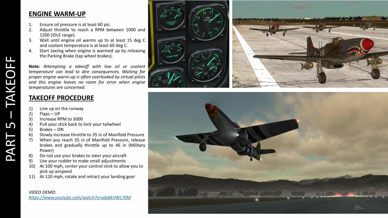
FFENGINE WARM-UP
1. Ensure oil pressure is at least 60 psi.2. Adjust throttle to reach a RPM between 1000 and
1200 (IDLE range).3. Wait until engine oil warms up to at least 15 deg C
and coolant temperature is at least 60 deg C.4. Start taxiing when engine is warmed up by releasing
the Parking Brake (tap wheel brakes).
Note: Attempting a takeoff with low oil or coolanttemperature can lead to dire consequences. Waiting forproper engine warm-up is often overlooked by virtual pilotsand this engine leaves no room for error when enginetemperatures are concerned.
TAKEOFF PROCEDURE
1) Line up on the runway2) Flaps – UP3) Increase RPM to 30004) Pull your stick back to lock your tailwheel5) Brakes – ON 6) Slowly increase throttle to 35 in of Manifold Pressure7) When you reach 35 in of Manifold Pressure, release
brakes and gradually throttle up to 46 in (MilitaryPower)
8) Do not use your brakes to steer your aircraft9) Use your rudder to make small adjustments10) At 100 mph, center your control stick to allow you to
pick up airspeed11) At 120 mph, rotate and retract your landing gear
VIDEO DEMO:https://www.youtube.com/watch?v=xdx8kVWL70M

30
VERY IMPORTANT
PAR
T 6
–LA
ND
ING
LANDING PROCEDURE
This picture sums up the landing procedure. The key to a successful landing in the P-51 is AIRSPEED. If you touchdown at the proper speed, you will avoid nasty surprises like bouncing or veering off the runway.
VIDEO DEMO: https://www.youtube.com/watch?v=JzQacZcwvdM
31
PAR
T 7
–EN
GIN
E M
AN
AG
EMEN
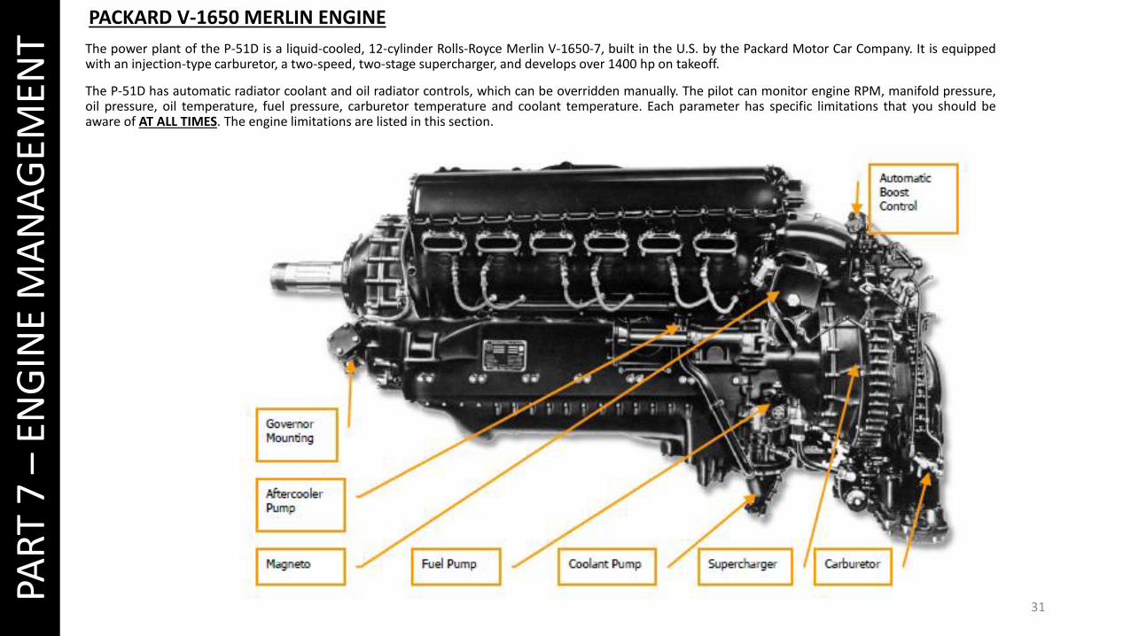
T The power plant of the P-51D is a liquid-cooled, 12-cylinder Rolls-Royce Merlin V-1650-7, built in the U.S. by the Packard Motor Car Company. It is equippedwith an injection-type carburetor, a two-speed, two-stage supercharger, and develops over 1400 hp on takeoff.
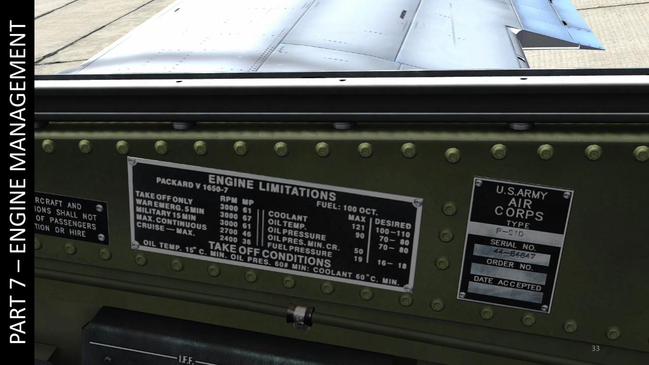
The P-51D has automatic radiator coolant and oil radiator controls, which can be overridden manually. The pilot can monitor engine RPM, manifold pressure,oil pressure, oil temperature, fuel pressure, carburetor temperature and coolant temperature. Each parameter has specific limitations that you should beaware of AT ALL TIMES. The engine limitations are listed in this section.
PACKARD V-1650 MERLIN ENGINE
32
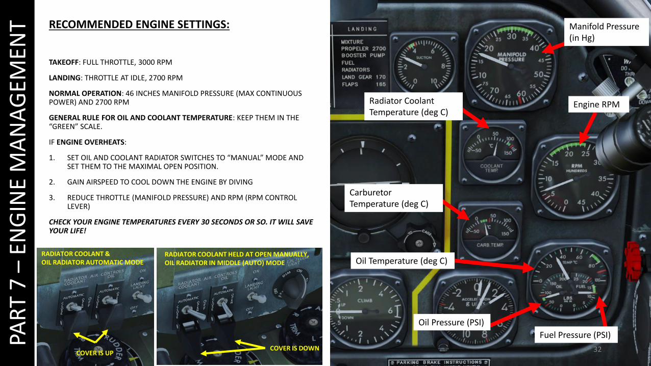
RECOMMENDED ENGINE SETTINGS:
TAKEOFF: FULL THROTTLE, 3000 RPM
LANDING: THROTTLE AT IDLE, 2700 RPM
NORMAL OPERATION: 46 INCHES MANIFOLD PRESSURE (MAX CONTINUOUS POWER) AND 2700 RPM
GENERAL RULE FOR OIL AND COOLANT TEMPERATURE: KEEP THEM IN THE “GREEN” SCALE.
IF ENGINE OVERHEATS:
1. SET OIL AND COOLANT RADIATOR SWITCHES TO “MANUAL” MODE AND SET THEM TO THE MAXIMAL OPEN POSITION.
2. GAIN AIRSPEED TO COOL DOWN THE ENGINE BY DIVING
3. REDUCE THROTTLE (MANIFOLD PRESSURE) AND RPM (RPM CONTROL LEVER)
CHECK YOUR ENGINE TEMPERATURES EVERY 30 SECONDS OR SO. IT WILL SAVE YOUR LIFE!
PAR
T 7
–EN
GIN
E M
AN
AG
EMEN
T Manifold Pressure (in Hg)
Engine RPMRadiator Coolant Temperature (deg C)
Oil Temperature (deg C)
Oil Pressure (PSI)
Fuel Pressure (PSI)
Carburetor Temperature (deg C)
RADIATOR COOLANT & OIL RADIATOR AUTOMATIC MODE
COVER IS UPCOVER IS DOWN
RADIATOR COOLANT HELD AT OPEN MANUALLY, OIL RADIATOR IN MIDDLE (AUTO) MODE
33
PAR
T 7
–EN
GIN
E M
AN
AG
EMEN
T
34
PAR
T 7
–EN
GIN
E M
AN
AG
EMEN
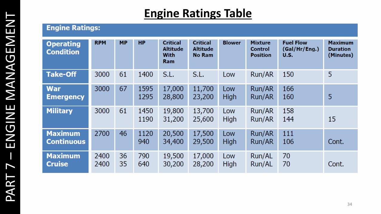
T Engine Ratings Table

35
PAR
T 7
–EN
GIN
E M
AN
AG
EMEN
T SUPERCHARGER BASICS
A supercharger is an engine-driven air pump or compressor that provides compressed air to the engine to provide additional pressure to the induction air so the enginecan produce additional power. It increases manifold pressure and forces the fuel/air mixture into the cylinders. The higher the manifold pressure, the more dense thefuel/air mixture, and the more power an engine can produce.
With a normally aspirated engine, it is not possible to have manifold pressure higher than the existing atmospheric pressure. A supercharger is capable of boosting manifoldpressure above 30 "Hg. For example, at 8,000 feet a typical engine may be able to produce 75 percent of the power it could produce at mean sea level (MSL) because the airis less dense at the higher altitude. The supercharger compresses the air to a higher density allowing a supercharged engine to produce the same manifold pressure athigher altitudes as it could produce at sea level.
Thus, an engine at 8,000 feet MSL could still produce 25” Hg of manifold pressure whereas without a supercharger it could produce only 22 "Hg. Superchargers are especiallyvaluable at high altitudes (such as 18,000 feet) where the air density is 50 percent that of sea level. The use of a supercharger in many cases will supply air to the engine atthe same density it did at sea level. With a normally aspirated engine, it is not possible to have manifold pressure higher than the existing atmospheric pressure.
36
PAR
T 7
–EN
GIN
E M
AN
AG
EMEN
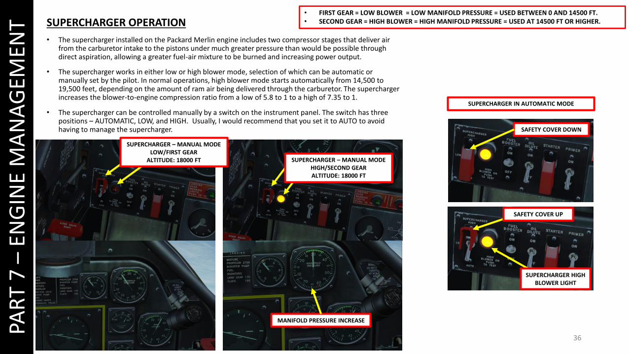
T SUPERCHARGER OPERATION
• The supercharger installed on the Packard Merlin engine includes two compressor stages that deliver air from the carburetor intake to the pistons under much greater pressure than would be possible through direct aspiration, allowing a greater fuel-air mixture to be burned and increasing power output.
• The supercharger works in either low or high blower mode, selection of which can be automatic or manually set by the pilot. In normal operations, high blower mode starts automatically from 14,500 to 19,500 feet, depending on the amount of ram air being delivered through the carburetor. The supercharger increases the blower-to-engine compression ratio from a low of 5.8 to 1 to a high of 7.35 to 1.
• The supercharger can be controlled manually by a switch on the instrument panel. The switch has three positions – AUTOMATIC, LOW, and HIGH. Usually, I would recommend that you set it to AUTO to avoid having to manage the supercharger.
• FIRST GEAR = LOW BLOWER = LOW MANIFOLD PRESSURE = USED BETWEEN 0 AND 14500 FT.• SECOND GEAR = HIGH BLOWER = HIGH MANIFOLD PRESSURE = USED AT 14500 FT OR HIGHER.
MANIFOLD PRESSURE INCREASE
SAFETY COVER DOWN
SAFETY COVER UP
SUPERCHARGER HIGH BLOWER LIGHT
SUPERCHARGER IN AUTOMATIC MODE
SUPERCHARGER – MANUAL MODE HIGH/SECOND GEARALTITUDE: 18000 FT
SUPERCHARGER – MANUAL MODE LOW/FIRST GEAR
ALTITUDE: 18000 FT
37
PAR
T 8
–A
IRC
RA
FT L
IMIT
ATI
ON
S
38
PAR
T 8
–A
IRC
RA
FT L
IMIT
ATI
ON
S
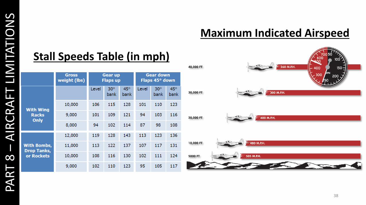
Stall Speeds Table (in mph)
Maximum Indicated Airspeed

39
PAR
T 8
–A
IRC
RA
FT L
IMIT
ATI
ON
S
Load Factor Limitations
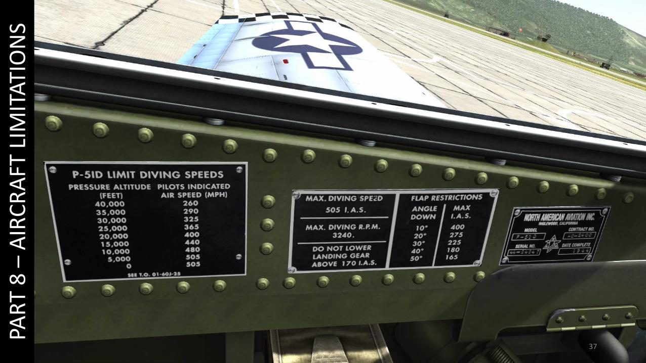
Maximum Allowable Dive Speeds

40
PAR
T 9
–W
EAP
ON
SARMAMENT OVERVIEW
• 6 x 0.50 cal M2 machineguns• 2 x M64 500 lbs Bombs• 8 x HVAR 5-in. Rockets

41
PAR
T 9
–W
EAP
ON
S
1
FIXED RETICLE MASK LEVER
GUNSIGHT RANGE SCALE(24 = 2400 ft)
GUNSIGHT MODE: FIXED/GYRO/FIXED+GYRO
GYRO POWER SWITCHUP = OFF/ DOWN = ON
GUNSIGHT BRIGHTNESS
GUNSIGHT WINGSPAN SETTER (CLICK AND DRAG)
GUNSIGHT
GUNSIGHT WINGSPAN SCALE (FT)
GUNSIGHT RANGE CONTROL (TWIST-GRIP THROTTLE)
2
34
Consult this tutorial about using the gunsight:https://www.youtube.com/watch?v=vCCuwzKV5wo
GUNSIGHT CONTROLS
GUNSIGHT
Your gunsight will show you where to shoot and when toshoot a target.
1. Gyro Power switch – ON (DOWN)2. Select Gunsight Mode (FIXED/GYRO/FIXED + GYRO)3. Set gunsight range scale (recommended: 1100 ft)
by using your twist-grip throttle (“Gunsight Rangeto Target Decrease/Increase” controls)
4. Set gunsight wingspan scale (recommended: 32 ftfor a Bf.109 or a FW190) by using the wingspansetter
5. Fire guns when the wings of the target fit withinyour gunsight reticle

42
PAR
T 9
–W
EAP
ON
S
1
WEAPON EMPLOYMENT (MACHINEGUNS)
1. Set your guns safety OFF by setting safety switch to GUNS (UP)2. Press the “GUN FIRE” button (Spacebar) to fire.
43
PAR
T 9
–W
EAP
ON
S
2
3
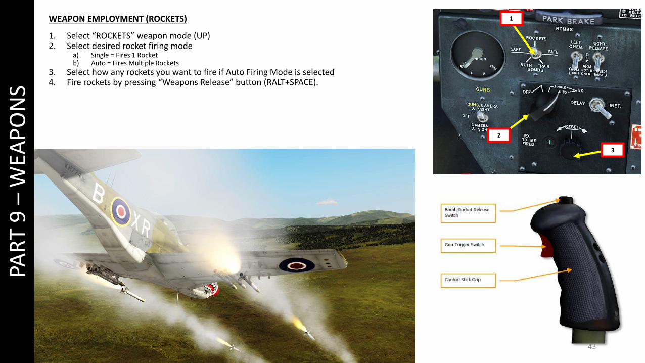
1WEAPON EMPLOYMENT (ROCKETS)
1. Select “ROCKETS” weapon mode (UP)2. Select desired rocket firing mode
a) Single = Fires 1 Rocketb) Auto = Fires Multiple Rockets
3. Select how any rockets you want to fire if Auto Firing Mode is selected4. Fire rockets by pressing “Weapons Release” button (RALT+SPACE).
44
PAR
T 9
–W
EAP
ON
S1
2
3
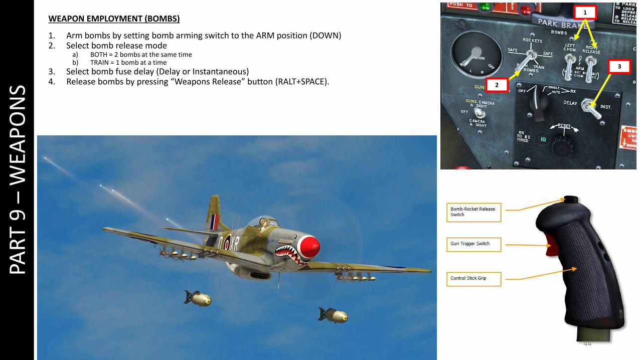
WEAPON EMPLOYMENT (BOMBS)
1. Arm bombs by setting bomb arming switch to the ARM position (DOWN)2. Select bomb release mode
a) BOTH = 2 bombs at the same timeb) TRAIN = 1 bomb at a time
3. Select bomb fuse delay (Delay or Instantaneous)4. Release bombs by pressing “Weapons Release” button (RALT+SPACE).
45
PAR
T 9
–W
EAP
ON
S2
3
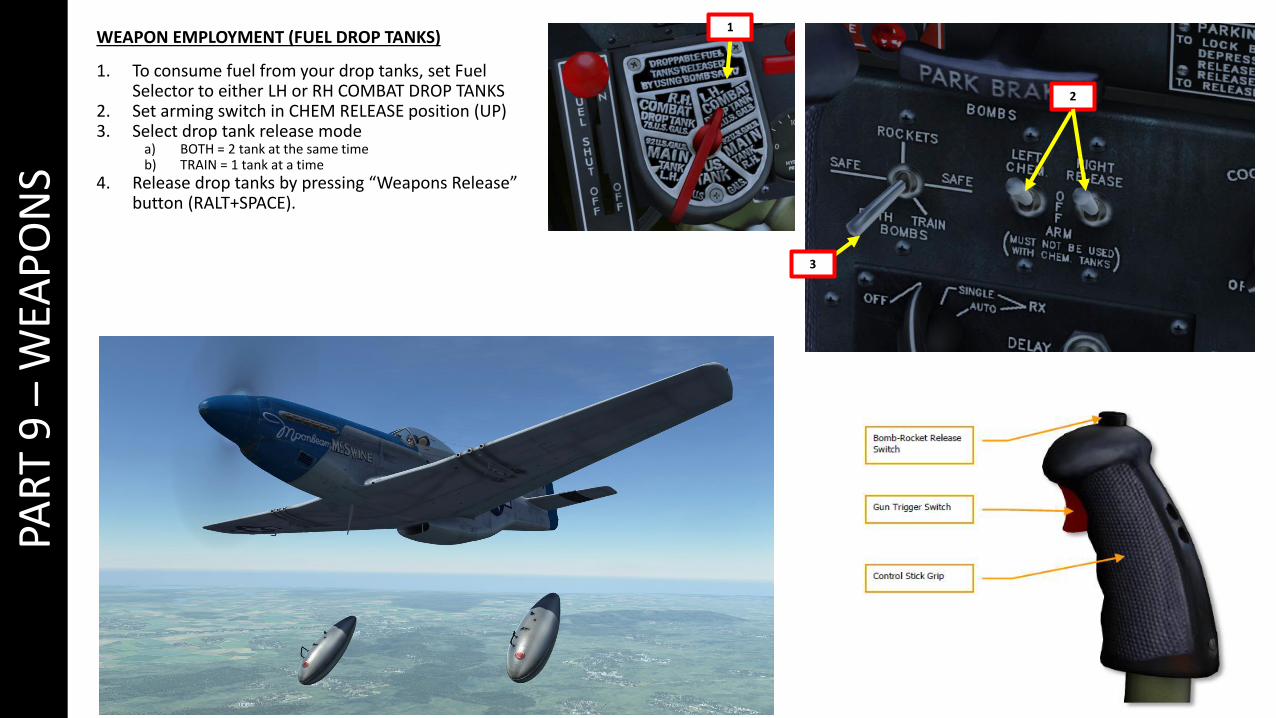
1WEAPON EMPLOYMENT (FUEL DROP TANKS)
1. To consume fuel from your drop tanks, set Fuel Selector to either LH or RH COMBAT DROP TANKS
2. Set arming switch in CHEM RELEASE position (UP) 3. Select drop tank release mode
a) BOTH = 2 tank at the same timeb) TRAIN = 1 tank at a time
4. Release drop tanks by pressing “Weapons Release” button (RALT+SPACE).
46
PAR
T 1
0 –
RA
DIO
1
2
PUSH-TO-TALK MICROPHONE BUTTON
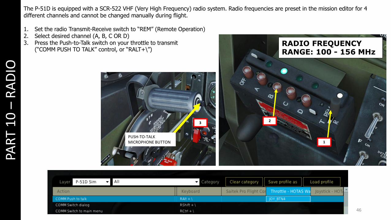
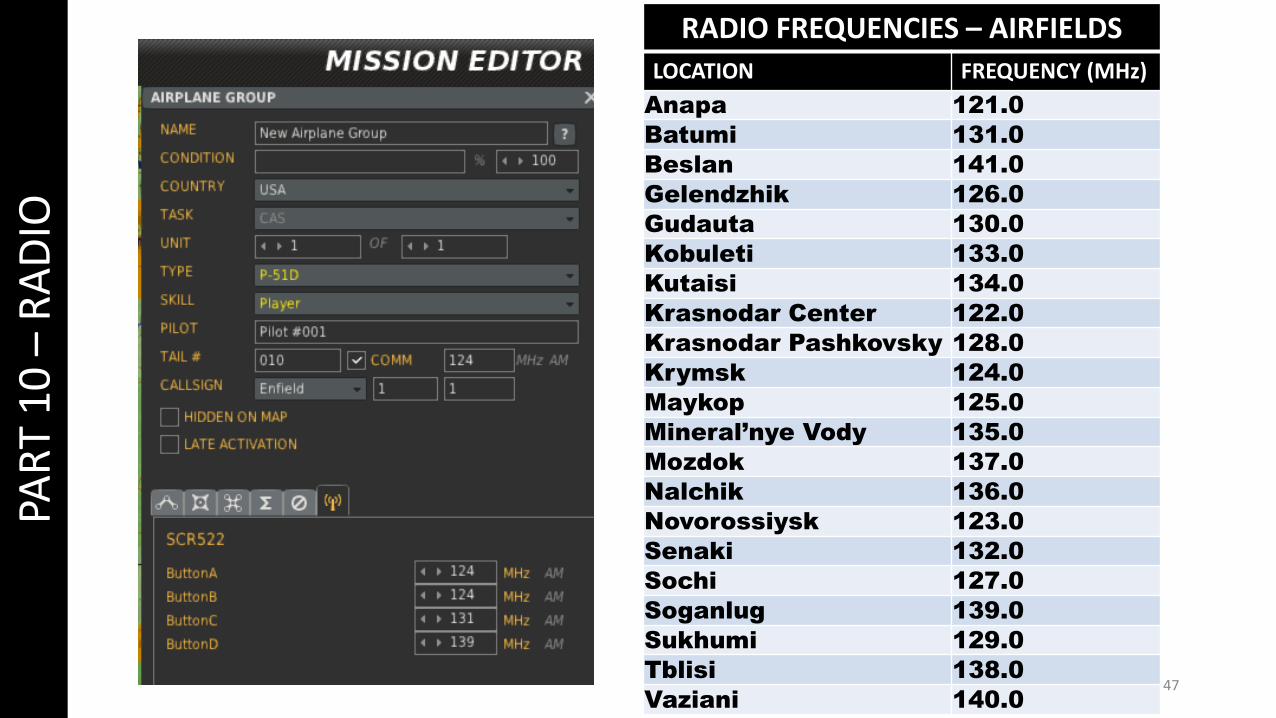
The P-51D is equipped with a SCR-522 VHF (Very High Frequency) radio system. Radio frequencies are preset in the mission editor for 4 different channels and cannot be changed manually during flight.
1. Set the radio Transmit-Receive switch to “REM” (Remote Operation)2. Select desired channel (A, B, C OR D)3. Press the Push-to-Talk switch on your throttle to transmit
(“COMM PUSH TO TALK” control, or “RALT+\”)RADIO FREQUENCY RANGE: 100 - 156 MHz
3
47
PAR
T 1
0 –
RA
DIO
RADIO FREQUENCIES – AIRFIELDS
LOCATION FREQUENCY (MHz)
Anapa 121.0
Batumi 131.0
Beslan 141.0
Gelendzhik 126.0
Gudauta 130.0
Kobuleti 133.0
Kutaisi 134.0
Krasnodar Center 122.0
Krasnodar Pashkovsky 128.0
Krymsk 124.0
Maykop 125.0
Mineral’nye Vody 135.0
Mozdok 137.0
Nalchik 136.0
Novorossiysk 123.0
Senaki 132.0
Sochi 127.0
Soganlug 139.0
Sukhumi 129.0
Tblisi 138.0
Vaziani 140.0

48
PAR
T 1
1 –
NA
VIG
ATI
ON
REMOTE INDICATOR MAGNETIC COMPASS
REMOTE INDICATOR COMPASS NEEDLE (POINTS TOWARDS CURRENT HEADING)
COURSE SETTER INDICATOR
COURSE SETTER KNOB
DIRECTIONAL GYRO
DIRECTIONAL GYRO CAGING KNOB
INDICATOR GYRO HEADING
MOST OF THE NAVIGATION MUST BE DONE VISUALLYIN THE P-51D. CONSULT THE GYRO AND REMOTEINDICATOR COMPASS (MAGNETIC COMPASS) TODETERMINE YOUR CURRENT HEADING.

49
PAR
T 1
2 –
AIR
CO
MB
AT
Dogfighting in the P-51D Mustang is an art that is easy to learn, but very difficult to master. On various forums, you will read a thousand different theories about “how to dogfight” or “why it sucks monkey balls” or “why it’s the most overpowered aircraft ever”. Everyone has an opinion on the Mustang, but few people have a truly “informed” opinion about it. I will try to give you some tips that are intended to be as unbiased and factual as possible.
First, the P-51D Mustang was built to be a high-speed, long-range escort fighter. While the majority of allied fighters like the Spitfire had a range of about 430 miles, a P-51 equipped with external fuel tanks had a range of about 1,650 miles. The distance between London and Berlin being approximately 600 miles, the Mustang became the aircraft of choice to escort the bombers during the bombing campaign over Germany.
Therefore, the Mustang is best used at altitudes of 25,000 ft and higher. This is where it will have the greatest performance advantage over the Bf.109 and the FW190. However, most dogfights occurring in multiplayer servers happen at lower altitudes between 5,000 and 15,000 ft, which is where the Messerschmittsand Focke-Wulfs will dominate in terms of climb rate and diving speed. This partially explains why the Mustang can sometimes seem “worst” in most aspects than other fighters at low altitude: it was meant to be a high-altitude fighter. If you happen to be forced to fight on the 109’s terms down low, you are at a serious disadvantage from the very beginning.
During dogfights, I would advise you to keep your energy state (airspeed and altitude) high at all times. These principles apply to every single aircraft, but particularly to the Mustang too. If you have to make a quick turn, you will notice that the Mustang’s wing configuration has an airfoil of a laminar-flow design, which provides low drag at high speeds but has the inconvenient of inducing violent accelerated stalls and spins if you pull too hard on the stick when turning and banking. A good trick is to deploy 10 to 20 degrees (1 to 2 notches) of flaps before beginning a turn and to retract your flaps immediately afterwards to gain back airspeed. The Mustang can have a surprisingly good turn rate when your flaps are deployed; this can be used to your advantage when you need to evade an enemy that is bouncing you.
It is also important for you to realize that the P-51D modelled in DCS is an early 1944 variant , while the Bf.109K-4 and FW.190D-9 entered service in late 1944. Therefore, the P-51D of early will underperform in comparison to the P-51D of late 1944 since the maximum allowable manifold pressure went from 67 inches of Hg to 75 inches of Hg, partly due to a change of fuel grade. There have been extensive and heated debates on “what fuel grade should be used” on the Eagle Dynamics forums.
While we could argue day and night about what the P-51D should or should not be, the conclusion remains the same. The P-51D must be used in the following way if you want to survive against experienced Bf.109 or FW.190 pilots.• Always fly with a wingman• Always fly with a high energy state (high airspeed and altitude)• Do not attempt to outclimb or outdive a 109 or 190• Bring the fight to high altitudes if you can to fly your plane in the combat environment it was designed for• Master your aircraft: know your engine limits and airspeed limits by heart and practice manoeuvers to avoid stalls and spins.
50
PAR
T 1
2 –
AIR
CO
MB
AT
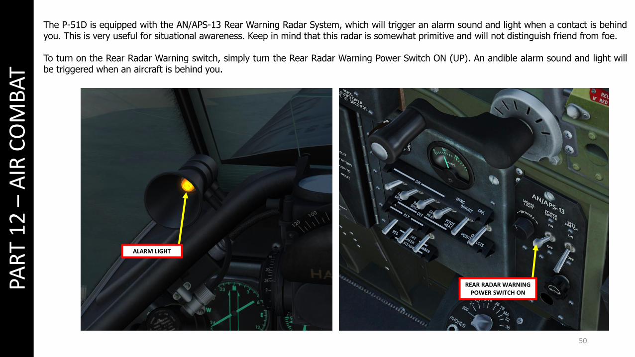
REAR RADAR WARNING POWER SWITCH ON
ALARM LIGHT
The P-51D is equipped with the AN/APS-13 Rear Warning Radar System, which will trigger an alarm sound and light when a contact is behindyou. This is very useful for situational awareness. Keep in mind that this radar is somewhat primitive and will not distinguish friend from foe.
To turn on the Rear Radar Warning switch, simply turn the Rear Radar Warning Power Switch ON (UP). An andible alarm sound and light willbe triggered when an aircraft is behind you.
51PAR
T 1
3 –
TAM
ING
TA
ILD
RA
GG
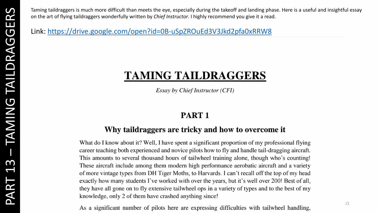
ERS Taming taildraggers is much more difficult than meets the eye, especially during the takeoff and landing phase. Here is a useful and insightful essay
on the art of flying taildraggers wonderfully written by Chief Instructor. I highly recommend you give it a read.
Link: https://drive.google.com/open?id=0B-uSpZROuEd3V3Jkd2pfa0xRRW8
52


![[Walk Around n°07] - North American P-51D Mustang ('96)](https://img.dokumen.tips/doc/110x75/5571f21a49795947648c2918/walk-around-n07-north-american-p-51d-mustang-96.jpg)