Embed Size (px)
Citation preview

Laser Tag Glove
Team 8 - Keng Yan Lim, Alex Korfel, Carlos Lara ECE 445 Project Proposal - Spring 2018
TA: Jacob Bryan
1

Table of Contents
1 Introduction 3 1.1 Objective 3 1.2 Background 3 1.3 High-level Requirement List 3
2 Design 4 2.1 Block Diagram 4 2.2 Physical Design 5 2.3 IR Module 7
2.3.1 IR Laser 7 2.3.2 IR Sensors 9 2.3.3 Contact Sensors 10
2.4 Control System 12 2.4.1 Microcontroller 12 2.4.2 Wireless Transceiver 17
2.5 LCD Module 18 2.6 Game Module 20 2.7 Power Supply 22
2.7.1 Battery 22 2.7.2 Converter 23 2.7.3 Power Consumption 26
2.8 Tolerance Analysis 27 3 Cost and Schedule 30
3.1 Cost 30 3.2 Schedule 32
4 Ethics and Safety 33 5 References 35
2

1 Introduction
1.1 Objective Our goal is to increase portability and boost laser tag immersion. To do this, we plan to develop a glove that contains the laser, a vest to detect the laser, and a wrist gauntlet displaying game information. As each player will wear a laser glove and small vest, our game will be easily portable and ready to play anytime anyplace. The ability to play a game anywhere will boost immersion and the fact that the player needs to make a “finger gun” to fire their laser, will make the game more entertaining and novel. A wireless transceiver will be used to sync all players into the game and keep track of score.
1.2 Background Laser tag is a great fast-paced game for all ages to pick up and enjoy. The usual hardware consists of a laser gun, a vest typically with four detection sensors, and a small screen displaying important game information. The point of the game is for players to use their laser to eliminate opponents by hitting their detection sensors and come out on top with the highest score or most lives remaining. Most laser tag games occur in a large dark maze at special facilities that are inconvenient to travel to. In addition, the gun and vest themselves can be heavy and cumbersome to operate for older and younger players. Our design will alleviate these issues while making an already exciting game that much more riveting.
1.3 High-level Requirement List A player’s shot (IR pulse) will register as a hit by the IR receiver if they shoot the receiver
at 20ft or closer. The glove and vest pair must be small and compact enough to be easily moved or
carried compared to those on the market. Preferably, more than four glove and vest pairs can be carried in a backpack.
Create a playable game of laser tag for 2 players that can be expanded to include 32 total players.
3
2 Design
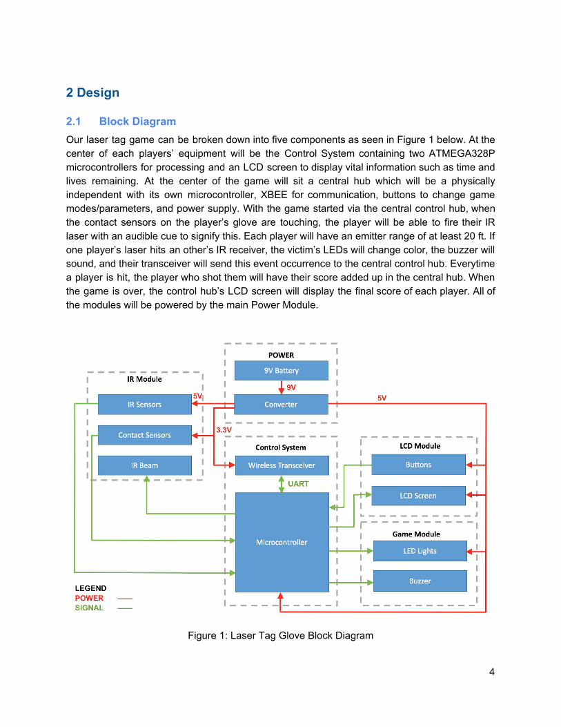
2.1 Block Diagram Our laser tag game can be broken down into five components as seen in Figure 1 below. At the center of each players’ equipment will be the Control System containing two ATMEGA328P microcontrollers for processing and an LCD screen to display vital information such as time and lives remaining. At the center of the game will sit a central hub which will be a physically independent with its own microcontroller, XBEE for communication, buttons to change game modes/parameters, and power supply. With the game started via the central control hub, when the contact sensors on the player’s glove are touching, the player will be able to fire their IR laser with an audible cue to signify this. Each player will have an emitter range of at least 20 ft. If one player’s laser hits an other’s IR receiver, the victim’s LEDs will change color, the buzzer will sound, and their transceiver will send this event occurrence to the central control hub. Everytime a player is hit, the player who shot them will have their score added up in the central hub. When the game is over, the control hub’s LCD screen will display the final score of each player. All of the modules will be powered by the main Power Module.
Figure 1: Laser Tag Glove Block Diagram
4

2.2 Physical Design As the name implies, the Laser Tag Glove will be a glove worn on each player’s right hand. The hand will utilize six contact sensors as shown in Figure 2. Three of the six contact sensors will be placed on the tips of the middle, ring, and pinky fingers. These fingers will then need to make contact with the “contact sensor patch” shown on the palm. This placement ensures that each player must have their hand in a “finger gun” position in order for the circuit to be drawn to ground (red circles in Figure 2) and the gun to function. The remaining two contact sensors will be placed at the base of the thumb and the base of the pointer finger. These two sensors must make contact in order to shoot the IR laser and it mimics the act of pulling the trigger on a “finger gun.” The IR emitter will be placed on the pointer finger and a red dot sight will be implemented in order to aim accurately (these compose the “IR Beam” in Figure 1). Figure 3b shows the LCD screen that will be implemented on the players. It will be located a bit past the wrist towards the arm. The screen will display information such as remaining time and lives. Figure 4 shows our physical design for the vest containing IR sensors. The IR beam will need to hit the IR sensors in order to register as a hit. The vest will contain its own microcontroller which will communicate with the glove’s microcontroller via I2C [9]. Physically the vest and glove will connect in a such a way that allows a comfortable amount of movement with minimal interference from the wiring.
Figure 2: Palm View of Glove Components
5

Figure 3: Player Control Center. (a) Central Control Hub. (b) Player’s Control Center.
6

Figure 4: Vest Component Layout
2.3 IR Module The IR Module consists of the IR sensors, IR transmitters, and contact sensors. The module as a whole is responsible for acting as the ‘gun’ and letting the system know that the player has been shot.
2.3.1 IR Laser The proposed 980nm IR laser will act as the signal that we will be firing towards the opponent’s IR sensors. This IR laser has to be sent in defined pulses that will allow the IR sensors to differentiate beams coming from the different players. The IR receiver will be looking for a carrier frequency of 38kHz and thus, the IR emitter will be modulated at the same 38kHz. The data pulses will be sent according to NEC protocol (founded by Nippon Electric Company). An
7
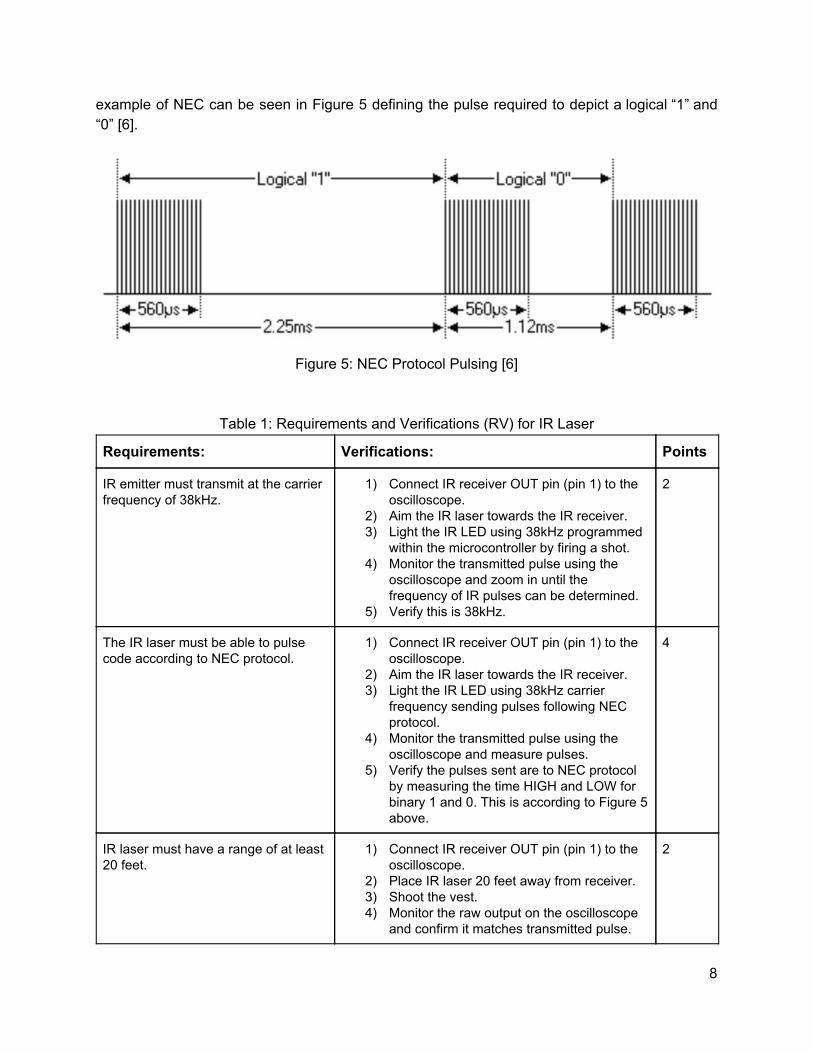
example of NEC can be seen in Figure 5 defining the pulse required to depict a logical “1” and “0” [6].
Figure 5: NEC Protocol Pulsing [6]
Table 1: Requirements and Verifications (RV) for IR Laser
Requirements: Verifications: Points
IR emitter must transmit at the carrier frequency of 38kHz.
1) Connect IR receiver OUT pin (pin 1) to the oscilloscope.
2) Aim the IR laser towards the IR receiver. 3) Light the IR LED using 38kHz programmed
within the microcontroller by firing a shot. 4) Monitor the transmitted pulse using the
oscilloscope and zoom in until the frequency of IR pulses can be determined.
5) Verify this is 38kHz.
2
The IR laser must be able to pulse code according to NEC protocol.
1) Connect IR receiver OUT pin (pin 1) to the oscilloscope.
2) Aim the IR laser towards the IR receiver. 3) Light the IR LED using 38kHz carrier
frequency sending pulses following NEC protocol.
4) Monitor the transmitted pulse using the oscilloscope and measure pulses.
5) Verify the pulses sent are to NEC protocol by measuring the time HIGH and LOW for binary 1 and 0. This is according to Figure 5 above.
4
IR laser must have a range of at least 20 feet.
1) Connect IR receiver OUT pin (pin 1) to the oscilloscope.
2) Place IR laser 20 feet away from receiver. 3) Shoot the vest. 4) Monitor the raw output on the oscilloscope
and confirm it matches transmitted pulse.
2
8

2.3.2 IR Sensors These sensors will be responsible for receiving the pulsed IR beams mentioned above that indicate whether the player is shot. These pulses will be the players’ unique tag. The IR receivers will have carrier frequency of 38kHz allowing for NEC protocol. This carrier frequency means that the LED output is set high by switching at 38kHz [12].
Table 2: RV for IR Sensors
Requirements: Verifications: Points:
Sensor must have a field of view of at least 45 degrees.
1) Setup operating IR receiver facing upwards with the OUT pin (pin 1) monitored using oscilloscope.
2) Use IR diode to manually sweep across the receiver dome and view raw data response on the oscilloscope.
3) Make sure data reads HIGH between ±22.5 degrees.
3
IR receiver must distinguish different pulsed signals sent at the 38kHz carrier frequency.
1) Setup operating IR receiver facing horizontally from an IR diode.
2) Apply 5V to +5V pin and monitor the OUT pin (pin 1) using an oscilloscope.
3) Pulse the IR LED according to NEC protocol at 38kHz and verify the receiver output matches the inputted pulse using the oscilloscope.
4) Cross check by connecting pin 1 to the Arduino and monitor the decoded pulses using the serial monitor.
5
9
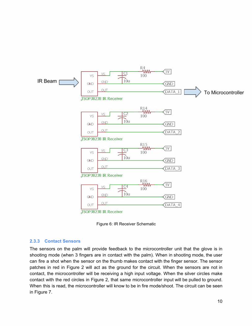
Figure 6: IR Receiver Schematic
2.3.3 Contact Sensors The sensors on the palm will provide feedback to the microcontroller unit that the glove is in shooting mode (when 3 fingers are in contact with the palm). When in shooting mode, the user can fire a shot when the sensor on the thumb makes contact with the finger sensor. The sensor patches in red in Figure 2 will act as the ground for the circuit. When the sensors are not in contact, the microcontroller will be receiving a high input voltage. When the silver circles make contact with the red circles in Figure 2, that same microcontroller input will be pulled to ground. When this is read, the microcontroller will know to be in fire mode/shoot. The circuit can be seen in Figure 7.
10

Table 3: RV for Contact Sensors
Requirements: Verifications: Points:
The microcontroller reads a logic high whenever the thumb makes contact with the pointer finger and the remaining three fingers are making contact with the palm.
1) Probe pin connecting contact sensor and microcontroller.
2) Make contact between fingers/palm and thumb/pointer finger to mimic “finger gun” shape.
3) Verify that the microcontroller is reading a logic high.
3
The microcontroller reads a logic low if the palm or the non-pointer fingers are not making contact with pointer finger and palm, respectively.
1) Probe pin connecting contact sensor and microcontroller.
2) Verify that the microcontroller is reading a logic low for the scenarios in steps 3-5
3) Test with an open palm. 4) Test with thumb/pointer finger contact, but
no fingers/palm contact. 5) Test with fingers/palm contact, but no
thumb/pointer finger contact.
2
The contact sensors maintain a max current flow of 9mA.
1) Probe the connection between the contact sensor and digital microcontroller pin with an ammeter.
2) Make contact with thumb/pointer finger and fingers/palm to give microcontroller a high signal.
3) Record current reading and make sure it is below 9mA.
1
Figure 7: Contact Sensor Circuit [11]
11

2.4 Control System
2.4.1 Microcontroller Being the brain of the project, this module is responsible for powering the LEDs when necessary, outputting various displays to the LCD screen, powering the IR emitter and buzzer depending on a series of signals from the IR sensors, contact sensors, and controlling the wireless transceiver. Due to limited pins on a single ATMEGA328P processor, we will be using two of them to share the workload using Inter-Integrated Circuit (I2C) protocol. One will be on the glove, the other on the vest. According to [9], the serial clock pins (SCL) and serial data pins (SDA) are used to send and receive data between microcontrollers. The SCL is used to keep timing while the SDA functions as a path to send or receive a single bit of data at a time. The microcontroller on the glove will act as the master while the one on the vest will function as the slave. Note that in Figures 10 and 11, the microcontroller used is the ATMEGA168. Our project will utilize two ATMEGA328P per player but we have used the ATMEGA168 as it has the same dimensions and pin layout as the 328 but is actually available in the EAGLE library. All labels for the various pins seen in the Figures can be sourced back to the microcontroller schematics in Figures 10 and 11. We designed two main game modes that the microcontroller will be responsible for: “Deathmatch” (who has the highest points in a limited amount of time) and “Last Man Standing” (who is the last surviving player). Depending on the game mode, the microcontroller will control the behavior of the LEDs and the ending point of the game differently. The finite state machines of these two modes can be seen in the next two pages in Figures 8 and 9 respectively.
12

Figure 8: FSM for Deathmatch
13
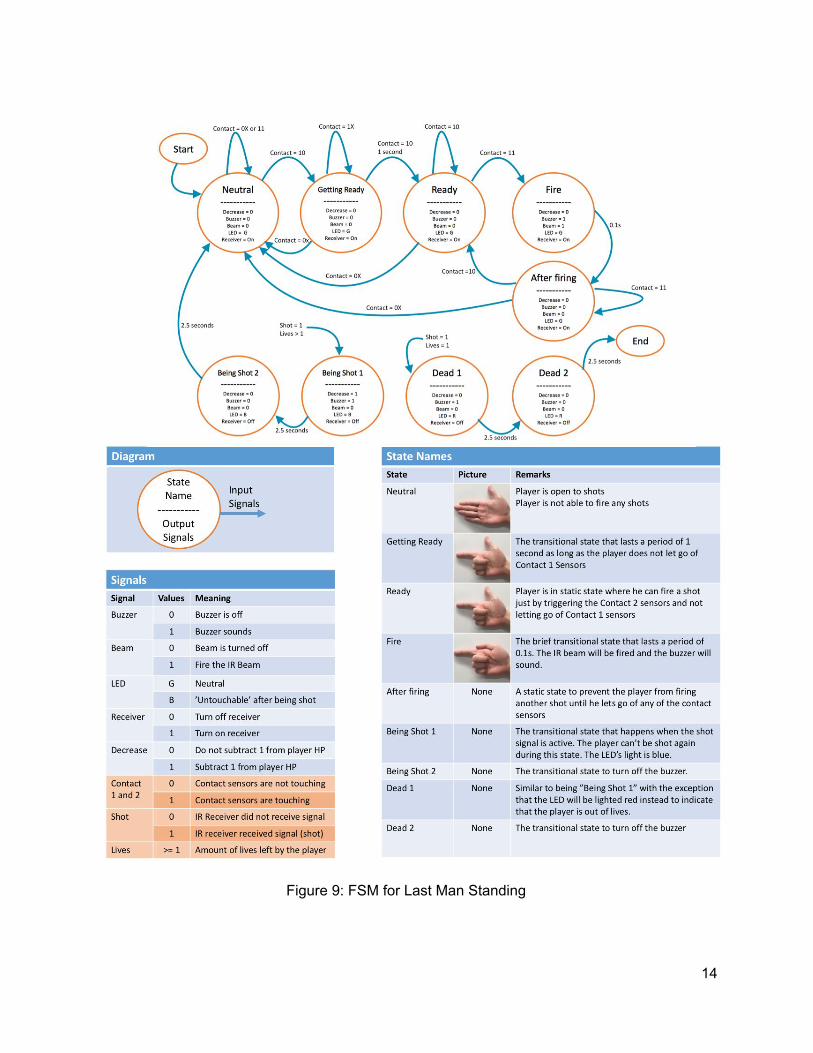
Figure 9: FSM for Last Man Standing
14

Table 4: RV for Microcontroller
Requirements: Verifications: Points:
Must be able to pulse the laser module at 38 kHz when contact sensor sends high signal.
1) Produce a high signal with the contact sensor by making contact with the pointer finger/thumb and fingers/palm
1
Powers the Piezo Buzzer at 4 kHz when contact sensor sends high signal to ensure at least 50 decibels.
1) Produce a high signal with the contact sensor by making contact with the pointer finger/thumb and fingers/palm
2) Use a mobile app that can read decibels in order to measure Piezo Buzzer noise
3) Verify that the buzzer produced a noise at 50 decibels minimum
1
Keeps track of game information such as player lives, score, and round time. Execute FSMs in Figures 8 and 9.
Round Time and Score: 1) Switch Game Mode to ‘Score with
Countdown timer’ 2) Player 1 to fire a certain number of
shots at Player 2 3) Player 2 fires a certain number of
shots at Player 1 4) Wait till specified Time period is over 5) Both players will try to fire shots again
(but must not be able to) 6) Check the scores on Player 1’s LCD
screen Player lives:
1) Switch Game Mode to ‘Deathmatch’ 2) Player 1 to fire shots at Player 2 until
Player 2’s LED lights turn red (indicates death)
3) Player 2 will try to fire some shots at Player 1 but must be unable to
1
15

Figure 10: Glove Schematic
Figure 11: Vest Microcontroller Schematic
16

2.4.2 Wireless Transceiver The wireless transceiver in the control system is mainly used to relay current game information to the master (player 1) as the game is going on. When the game begins, each player will be synced to player 1’s set time limit. During the game, when a player has hit another player successfully, the wireless transceiver (on the person who was shot) will relay the information to the master (player 1) to keep track of the score. The schematic for the XBEE can be seen in Figure 10 above.
Table 5: RV for Wireless Transceiver
Requirements: Verifications: Points
Transmission range of at least 20 feet indoors even with physical obstacles such as walls.
1) Switch Game Mode to ‘Score with Countdown timer’.
2) Players 1 and 2 to stand 25 feet apart. 3) Player 2 will fire a shot at Player 1
(buzzer of Player 1 must sound and LED changed to blue as proof).
4) The score of player 2 must have increased by at least 1 to reflect that the signal was successfully sent via the wireless transceivers.
5) Repeat while Player 1 is taking cover behind a wall.
2
17

2.5 LCD Module The LCD module presents to player 1 an interactive module where he can navigate a programmed game menu via the buttons. As for all the other players, the LCD screen displays important information such as the current health bar, time left in the game, and other game features that we can think of along the way. As indoor use is the main intention, all tests will be conducted inside with well lit rooms as the worse case. As sunlight is not normally in the 980nm spectrum (wavelength of the laser), the game should work outside as well.
Table 6: RV for LCD Module
Requirements: Verifications: Points:
Screen must be backlit and comfortably viewed in both a dark and well lit room (developed for indoor use). Brightness must be adjustable.
1) Step in a dark room with LCD screen. 2) Place screen 1 ft away, as if telling the
time on a watch. 3) Make sure text on screen is visible
without strain or squinting. 4) If not, adjust brightness up or down to a
point where strain is alleviated. 5) Repeat steps b) through d).
1
LCD acts as an interactive menu for player 1 to set game settings.
1) Click each of the four buttons. 2) Confirm each menu/sub-menu can be
accessed and/or changed. 3) This update in game modes must reflect
in the Arduino code.
4
Screen response time of less than 300ms.
1) Power on display and wait in main menu. 2) Use slow-motion camera on phone. 3) Traverse through all menus and film. 4) Convert from measured frames to total
seconds using the camera’s fps rate. 5) Verify time is less than 300ms.
2
Reflect a decrease in lives when a player is shot or an increase in score when a player shoots another. Based on the game mode.
1) Grab a set of gloves. 2) Shoot each other’s vests. 3) Confirm that when you’re shot, the total
lives on the screen decreases when in total life mode.
4) Confirm that when you shot someone, your score increases when in score mode.
5) Repeat for all game modes and players.
3
18
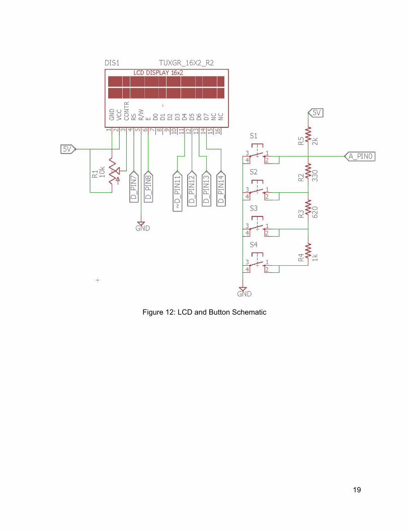
Figure 12: LCD and Button Schematic
19
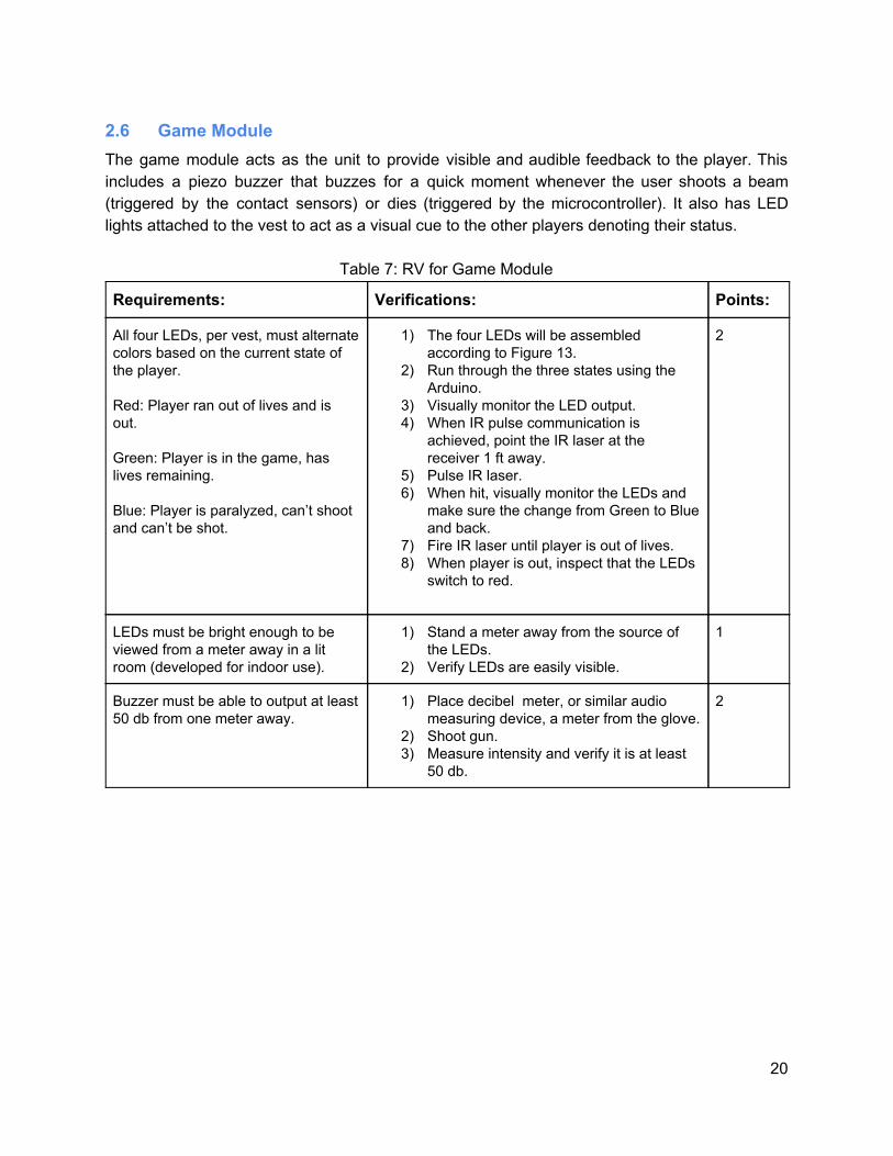
2.6 Game Module The game module acts as the unit to provide visible and audible feedback to the player. This includes a piezo buzzer that buzzes for a quick moment whenever the user shoots a beam (triggered by the contact sensors) or dies (triggered by the microcontroller). It also has LED lights attached to the vest to act as a visual cue to the other players denoting their status.
Table 7: RV for Game Module
Requirements: Verifications: Points:
All four LEDs, per vest, must alternate colors based on the current state of the player. Red: Player ran out of lives and is out. Green: Player is in the game, has lives remaining. Blue: Player is paralyzed, can’t shoot and can’t be shot.
1) The four LEDs will be assembled according to Figure 13.
2) Run through the three states using the Arduino.
3) Visually monitor the LED output. 4) When IR pulse communication is
achieved, point the IR laser at the receiver 1 ft away.
5) Pulse IR laser. 6) When hit, visually monitor the LEDs and
make sure the change from Green to Blue and back.
7) Fire IR laser until player is out of lives. 8) When player is out, inspect that the LEDs
switch to red.
2
LEDs must be bright enough to be viewed from a meter away in a lit room (developed for indoor use).
1) Stand a meter away from the source of the LEDs.
2) Verify LEDs are easily visible.
1
Buzzer must be able to output at least 50 db from one meter away.
1) Place decibel meter, or similar audio measuring device, a meter from the glove.
2) Shoot gun. 3) Measure intensity and verify it is at least
50 db.
2
20

Figure 13: LED Schematic
Figure 14: Buzzer Schematic
21
2.7 Power Supply The power module will power the components in our design. The laser tag glove will be battery powered with regulation so that each component gets the necessary voltage and current to function. The power supply will be located near the vest with battery holders.
2.7.1 Battery Our power supply will utilize a 9V Alkaline battery in a battery holder. The components that require the most supply current are our laser module and XBEE transceiver. The batteries used for the glove will have around a 500 mAh battery capacity. When assuming maximum currents, the battery will power the laser tag glove for about 1.36 hours and 2.26 hours for the typical currents. The calculations for our estimated times can be found in Table 10. If the battery does not meet the time requirements once more tests are done, a battery holder that holds two 9V batteries will be implemented in order to extend the usage time.
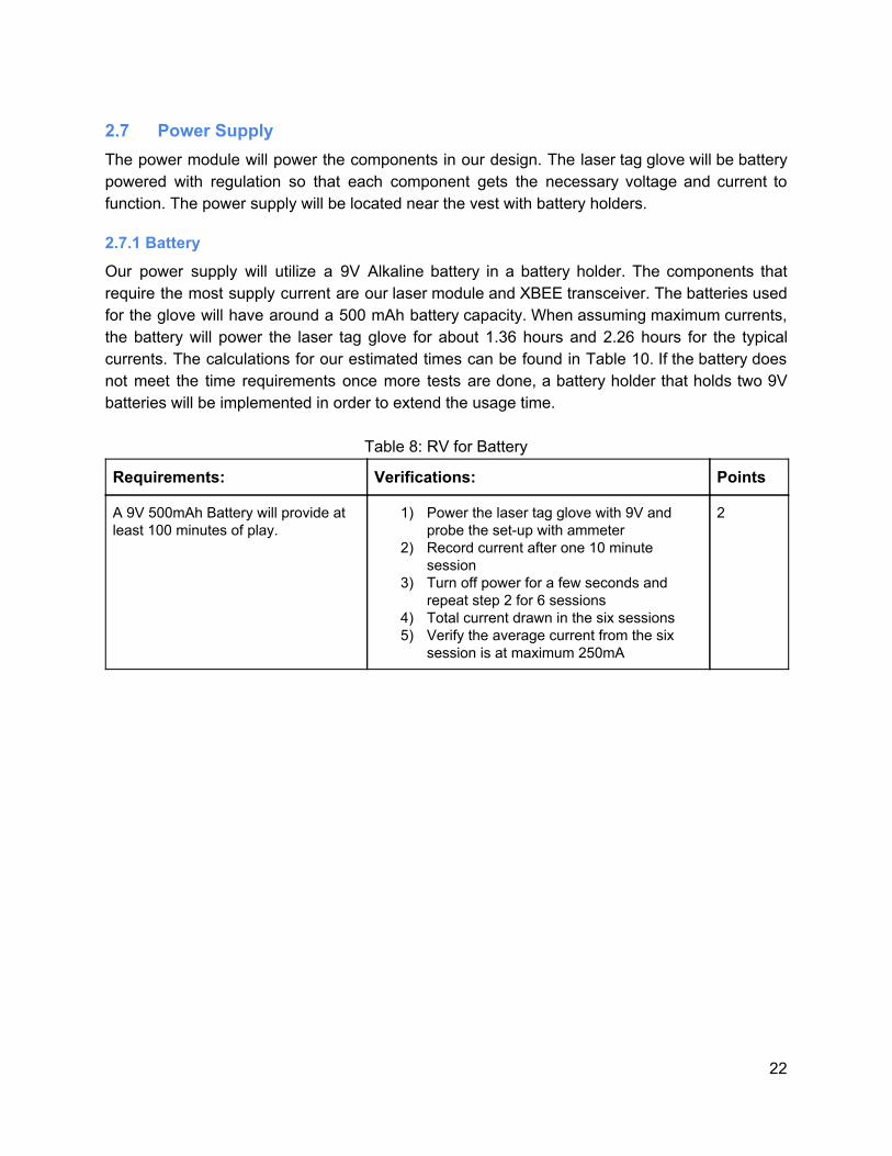
Table 8: RV for Battery
Requirements: Verifications: Points
A 9V 500mAh Battery will provide at least 100 minutes of play.
1) Power the laser tag glove with 9V and probe the set-up with ammeter
2) Record current after one 10 minute session
3) Turn off power for a few seconds and repeat step 2 for 6 sessions
4) Total current drawn in the six sessions 5) Verify the average current from the six
session is at maximum 250mA
2
22

2.7.2 Converter
The LCD display requires an input voltage of 5V while our microcontroller, buzzer, and laser module require around 3.3V. The remaining components such as the IR sensors operate at ranges of 2.5 to 5.5 volts. We plan on implementing separate buck converter in order to step-down the 9 volts from the battery to the appropriate levels for each device. The converters will need to have low voltage ripple in order for our devices to operate correctly and consistently.
Table 9: RV for converter
Requirements: Verifications: Points
9.0V to 5.0V DC-DC Buck converter must supply 5.0± 5%V with a maximum output current of 3A.
1) Probe the 9-5V Vout Pin with a voltmeter when the circuit is supplied by 9V DC.
2) Ensure that the voltmeter reads the desired 5V±5%V.
3) Probe the 9-5V Vout Pin with an ammeter when the circuit is supplied by the 9V DC.
4) Ensure the ammeter is below the converter’s 3A rating.
3
9.0V to 3.3V DC-DC Buck converter must supply 3.3± 5%V with a maximum output current of 3A.
1) Repeat steps 1-4 above for the 9-3.3V Vout Pin.
3
Figure 15 is the TPS563208DDCR converter we purchased from Mouser. The design is the typical application schematic found in the Texas Instruments datasheet [5]. We had to make sure to change the value of certain components in order to get the proper output voltage based on our input voltage. Equation (1) can be used to determine the resistor values for our desired output voltage of 5V.
out .768 x (1 1/R2) V = 0 + R (1)
Based on our calculations R2= 54.9kΩ for the 5V output and R2=33.2kΩ for the 3.3V output. R1 is 10kΩ for both converter circuits. The Inductor value found in Figure 15 is simply taken from the recommended component table found in [5]. The 3.3µH ensures our ripple current is at an acceptable level of ±10%. The 3.3V converter will use a 2.2µH instead of the 3.3µH found in Figure 15. In order to find the capacitor values for our converter, we had to stay within the suggested capacitance range in [5]. The capacitor values in Figure 15 apply to both the 5V and 3.3V
23

converters and will maintain an output voltage ripple of ±5%. We need to make sure to select capacitors that have a low equivalent series resistance (ESR) since the high switching frequency (580 kHz) will lead to higher losses. [5] recommends using low-ESR ceramic capacitors, so we will try to stay within the recommended guidelines. This schematic would be the foundation for our power module. Once constructed, we will be able to get 5V and 3.3V from the two seperate VOUTs. The 5V and 3.3V will meets the requirements of all the devices we plan on using. Figure 16 shows our schematic with both converters and the 9V battery clip that will power both of them.
Figure 15: 9v Input 5v Output Buck converter [5]
24

Figure 16: 9V to 9-5V/9-3.3V Buck Converter Schematic [5]
25

2.7.3 Power Consumption In order to get a proper estimate of the battery life for our project, the power consumption of each device must be considered. The values found in Table 10 were taken from each load’s respective datasheet.
Table 10: Max and Typical Power Consumption of one glove
Load (Active mode):
Input Voltage (V):
Max Current (mA):
Max Power (mW):
Typical Current (mA):
Typical Power (mW):
IR Laser Module
3 82 246 35 105
Visible Light Laser Module
3 70 210 35 105
4 Infrared Receivers
3.3 20 66 2.8 9.24
Microcontroller 3.3 0.2 0.66 0.2 0.66
XBEE Wireless Transceiver
3.3 50 165 50 165
LCD Screen 5 0.4 2.00 .35 1.75
Piezo Buzzer 3.3 12 39.6 10 33
Tri-color LED 3.3 20 66 20 66
Converter (9V-5V)
9 0.75 6.75 .59 5.31
Converter (9V-3.3V)
9 0.75 6.75 .59 5.31
Total: 256.10 808.74 154.53 496.27
Based on our results, Equation (2) is used in order to find our expected maximum and typical battery life.
stimated Hours attery Capacity .7 (mAh)/Load Current(mA) E = B * 0 (2)
The 0.7 multiplier in Equation (2) accounts for external factors that may affect the efficiency of a battery [7]. The typical battery capacity for a 9V Alkaline battery is around 500mAh. When considering the worst-case current, the expected battery life is around 1.36 hours. However, the worst-case scenario assumes each device is running at their maximum rating and that they are constantly running. For example, our IR laser and buzzer will only turn on whenever the player activates the trigger. Also, each device will most likely be running at the typical current ratings rather than the maximums. Therefore, our
26

more likely battery life is 2.26 hours. Based on the calculations, the battery life is appropriate since this will be our prototype model that will mainly be used for demonstration purposes.
2.8 Tolerance Analysis One critical requirement that should be explored in more detail is our IR module. The IR module is comprised of the IR laser, IR sensors, and contact sensors. A functioning IR module will allow us to meet our high-level requirement of creating a playable game of laser tag. This module is critical since it plays a large role in the communication between players. Each player needs to be identified in order to keep track of score and make sure players’ shots register as hits. The first requirement that must be analyzed is the the time it takes to send 32 bits of information. The NEC protocol will be used in order for our IR receivers to identify the player’s IR beam. NEC protocol is standard method used for IR devices that need to identify certain information. For example, TV remotes utilize NEC in order to identify which brand of television to control and the specific function, such as changing the channel. The IR signal is pulsed in a way such that the receivers output a logical “one” or “zero” depending on the beam duration. Figure 17 showcases the amount of time required in order to send a specific 32 bit message with our 38kHz IR signal.
Figure 17: Expanded NEC protocol [8]
NEC protocol requires a 9ms leader code followed by a 4.5ms wait time. Figure 17 then shows that the 32 bit signal is comprised of an address and data code. The address code identifies the device that will be controlled. The data code will then identify the player that shot and award them a point. Each 8 bit address and data code are followed by their inverted versions. For example, if the address code is “01010101,” it will be followed by “10101010” then the 8 bits of the data code. This standardized method of identifying IR signals will greatly assist us in making sure each player is identified in our game. Using the NEC protocol, our goal is to ensure “pulling the trigger” with the contact sensors will provide enough time for the laser module to send the whole message. In order ensure our project will work, the duration of the NEC protocol must be measured. As shown in Figure 5, a logical “one” results from a high signal lasting 560µs followed by a low signal for 1690µs. A logical “zero” will be read when a high signal lasts 560µs followed by a 560µs low signal duration. Therefore, a logical “one” takes 2.25ms while a logical “zero” only takes 1.12ms. Since both the address and data code’s are followed by their complements, any 32 bit message will have 16 “ones” and 16 “zeros”. Therefore Equation (3) calculates the message duration.
otal T ime 3.5ms 6 2.25ms) 6 1.12ms) 7.42ms T = 1 + 1 * ( + 1 * ( = 6 (3)
Next, the continuous and rapid firing of the laser must be taken into consideration. In order to simulate this, a cell phones’ stopwatch app was used. Our fastests time between phone taps was 110 ms.
27

Therefore, our calculations show that there will be enough time for the NEC protocol to deliver the full 32 bit message. Also, our IR module and receivers will have a pulsing and carrier frequency of 38kHz. Equation (4) and (5) show the maximum pulse length that can be sent with a 38kHz signal.
requency 8kHz f = 3 (4)
mallest Pulse duration 1/f 6.31µs S = = 2 (5) The shortest pulse that must be sent with the NEC protocol is the 560µs signal. At 38kHz pulses as small as 26.31µs can be sent, so no issues should arise with following the NEC protocol. The calculations above confirm that our laser module and IR receivers will have enough time to follow the NEC protocol. The only remaining issue with our IR module is to make sure the IR receiver will be able to detect the IR beam emitted from the laser module at our desired distances. Figure 18 from [10] gives us an idea of the worst case receiving distance.
Figure 18: Max receiving distance vs. Radiant Intensity [10]
As proposed, our laser tag game must have a minimum distance of 20 feet. According to figure 18, our Vishay IR receivers will need at least 100 mW/sr in the worst case sample of free air to achieve this distance. Based on datasheet information, our laser module will easily achieve our desired minimum distance of 20ft. The Vishay IR receivers we are using are commonly used alongside the IR emitters found in [10]. The emitter found in [10] is known as the TSAL6100 emitter and it has a maximum radiant intensity of 130 mW/sr. When referring to Figure 18, 130 mW/sr will be around 20ft at the worst case sample. Based on that information, our laser module will be able to
28

achieve at least that distance since they are much more powerful. This assumption can be made since the TSAL6100 is an IR diode. The diode’s radiant intensity disperses around itself while our laser module focuses the IR signal into a very fine beam. Therefore, our IR receivers will pick up the IR signal from our laser modules at a minimum of 20 feet.
29

3 Cost and Schedule
3.1 Cost Table 11: Total Cost
Parts (Costs are for Two Players)
Part Name Supplier Unit Cost Quantity Total
Infrared Receivers Mouser $0.881 8 $7.05
IR Laser (1mW) Ali Express $12.00 2 $24.00
Red Laser (1mW) Ali Express $3.50 2 $7.00
Sensing Fabric SparkFun $24.95 1 $24.95
Conductive Thread SparkFun $3.95 1 $3.95
Leather Glove Amazon $9.99 2 $19.98
IR Module $86.93
Microcontroller Adafruit $5.95 4 $23.80
XBEE Wireless Transceiver Adafruit $22.95 2 $45.90
Control Module $69.70
LCD Screen Adafruit $10.95 1 $10.95
Buttons (10 pack) Adafruit $2.50 1 $2.50
LCD Module $13.45
Piezo Buzzer Adafruit $1.50 2 $3.00
Tri-color LED (10 pack) Adafruit $9.95 1 $9.95
Game Module $12.95
9V Alkaline Battery (2 pack) Walgreens $6.00 1 $6.00
Converter (9V-5V) Mouser $1.30 2 $2.60
Converter (9V-3.3V) Mouser $1.30 2 $2.60
Power Module $11.20
Part Total $194.23
30

Labor
Team Member Hourly Rate Total Hours Multiplier Cost
Alexander Korfel $32 150 2.5 $12,000
Carlos Lara $32 150 2.5 $12,000
Keng Yan Lim $32 150 2.5 $12,000
Labor Total $36,000
Grand Total = Labor + Parts $36,194.23
31

3.2 Schedule Table 12: Semester Schedule
Date Alex Carlos Kengyan All
2/19/18 Design IR receiver, LED, and XBEE transceiver circuits.
Design converter schematics and find total power consumption.
Start work on LCD Module.
Place orders for parts. Work on design document.
2/26/18 Set up IR LED - receiver circuit and begin testing.
Completely assemble converter design on breadboard. Begin contact sensor circuit design.
Continue working on LCD Module (if not completed).
Design Review.
3/5/18 Test transceiver - transceiver circuit communication.
Ensure contact sensor properly turns on laser module and Piezo Buzzer.
Work with Alex on the transceiver.
Soldering Assignment.
Checkpoint: Finish Prototyping with Arduino
3/12/18 Integrate IR laser with IR LED - receiver circuit.
Implement visible light laser module for safer IR aiming. Ensure they fall at or below the 1mW rating.
Integrate LCD Module with entire system.
Design PCB Design together.
Checkpoint: Completed PCB Design
3/19/18 Spring Break
3/26/18 Refine IR laser transmission pulses.
Make sure every device is properly powered/functional for the PCB design.
Make sure LCD Module works with PCB.
Work on replacing Arduino board with PCB.
Checkpoint: Completed PCB Design Round 2
4/2/18 Test range capabilities of IR laser and IR receiver.
Test contact sensor sensitivity to ensure “finger gun” behavior. Adjust buzzer sounds based on shooting/being shot.
Work on setting a game mode via player 1 and syncing to all players in the game.
4/9/18 Integrate IR laser Layout components Test setting of game Prepare for Mock.
32

into glove and IR receiver onto vest.
on glove to ensure durability and electrical safety.
modes and syncing between all players.
Demo (prototyping week)
Checkpoint: Integrated PCB
4/16/18 Test assembled capabilities.
Debug likely integration issues once other modules are complete.
Debugging any existing issues.
Touch up, assembled testing, debugging.
4/23/18 Debug any transmission issues.
Record project parameters and waveforms for final paper/presentation.
Aid teammates in any issues they are facing.
Work on Final Paper.
4/30/18 Work on Final Presentation.
Work on final presentation.
Work on Final presentation.
Prepare for Final Presentation.
4 Ethics and Safety Many ethical and safety concerns must be considered when creating our project. An obvious issue that comes to mind is that the project revolves around the use of infrared light. While developing our project we must be mindful of the lasers since they can cause damage when pointed directly at one’s eyes [2]. Our project is not meant to cause harm to anyone, and it is only meant to be an enjoyable experience for those who use it. However, intentional misuse of the product could lead to severe eye damage such as blindness. This can occur if the laser is pointed directly at people, vehicles, or any living thing with their eyes exposed. In order “to hold paramount the safety, health, and welfare of the public,” we must design the project in a way which minimizes any safety hazards [1]. Since the laser portion of the project is a key component, we cannot simply make it safer or remove the hazards. We can minimize accidents where players point at each other’s eyes with our sensor location. For example, by placing the sensors below the shoulders, on the stomach, and on the back we make sure that one does not need to aim towards the face which limits exposure to the eyes. Another factor we considered was the power of our laser module. Lasers can cause eye damage even at low wattage, such as 5mW. A regular 60W light bulb uses more power, but the light is spread around making it much less dangerous than the concentrated laser. Due to this safety concern, we plan on using a 1mW IR laser module. At one milliwatt, the laser will need to hit the eye for seconds in order to cause permanent damage. Our design will release the IR beam for a very short duration (milliseconds) when pressing the trigger, making it less likely to cause damage even if exposure to the eyes occurs for some reason. These ratings would maker our laser module a class 3B laser [4]. A class 3B laser is dangerous with direct exposure to the eye. However, the laser is class 3B primarily due to the fact that it is infrared light, which is more hazardous than visible light. When taking the power into consideration, our laser fits the power classifications of a class 2 laser. A class 2 laser must be 1mW or less and are considered relatively safe when used
33

properly. Since our laser will fall within the class 2 power range, we believe it minimizes the dangers associated with infrared. Lasers exist with various power outputs, ranging from harmless to strong enough to damage the body. Ideally we would want a completely harmless laser module, but it would severely limit the range of the game. Our 1mW laser will be safe if used as instructed while maintaining an enjoyable range of 20 ft+. However, another danger of IR light is that it is not within the visible spectrum of human sight. Visible light can be seen, so it is much easier to avoid whenever you interact with it. During development of our product we must be aware where the laser module points at all times and consider factors such as reflection. This is a hazardous component of the product, since you might point towards someone’s eyes and not even know that it is occuring. We plan on reducing this hazard by placing a visible light sight so the player knows the general area of where they are aiming. Also, our product is intended for people of varying ages and background. Therefore, many of them might not know of the dangers associated with lasers and IR light. The final product would come with safety warnings and information about lasers in order to notify them about proper usage of the product. Hopefully this reduces accidental misuage of the product and allows them to have fun in a safe manner. We currently have no plans of using safety equipment such as goggles when playing, but if the laser modules we purchase go slightly over the 1mW rating we would implement safety equipment. Another safety issue associated with our product is the contact with the human body and electrical equipment. Our laser tag glove is meant to be worn and it will contain electrical components within. We need to make sure that all of the circuitry is properly closed off in order to prevent current to travel through the person’s body. The player will likely be running around, so we need to make sure that bodily fluids such as sweat will not damage or short the electric components. Our soldering and connecting of the circuit has to be reliable since everything must stay in place regardless of each player’s movements. Since conductive thread will be sown into the glove, a rubber glove will be placed inside to act as an insulator. Also, since our product will be battery powered we must make sure each component is powered at its appropriate voltage and current ratings. This is necessary since we would not want components to blow up or heat up to dangerous levels. Minimizing these safety concerns is our primary goal, so we plan on considering all of these factors when designing and developing the laser tag glove. By regulating the current flowing through the circuit and carefully planning the product’s connections, we plan on our product being safe and reliable even through many uses. During testing, we plan on wearing a rubber glove under the laser tag glove in order to ensure the electricity cannot flow into the wearer’s body. Overall, our project comes with safety hazards that must be considered. The hazards are unavoidable due to the need for electricity and lasers. However, we will consider and implement the proper methods to make the laser tag glove completely safe when used correctly. Our main goal for the project is to create a fun product and have others enjoy it. As engineers, it is our duty to implement our designs with the well being of others in mind.
34

5 References [1] Ieee.org, "IEEE IEEE Code of Ethics", 2016. [Online]. Available: http://www.ieee.org/about/corporate/governance/p7-8.html [Accessed: 28- Jan- 2018]. [2] “Can a pocket laser damage the eye?” Scientific American, Available: www.scientificamerican.com/article/can-a-pocket-laser-damage/ [Accessed: 03-Feb-2018] [3] Layton, Julia. “How Remote Controls Work.” HowStuffWorks, HowStuffWorks, 10 Nov. 2005, Available: www.electronics.howstuffworks.com/remote-control. [Accessed: 03-Feb-2018] [4] “Laser safety.” Wikipedia, Wikimedia Foundation, 18 Feb. 2018, en.wikipedia.org/wiki/Laser_safety. [Accessed: 18-Feb-2018] [5] "TPS563208," Texas Instruments. [Online]. Available: http://www.ti.com/lit/ds/symlink/tps563201.pdf. [Accessed: 20-Feb-2018] [6] Bergmans, S. (2018). SB-Projects - IR - NEC Protocol. [online] Sbprojects.net. Available at: https://www.sbprojects.net/knowledge/ir/nec.php [Accessed: 20-Feb-2018]. [7] “Battery Life Calculator.” Battery Life Calculator | DigiKey Electronics, www.digikey.com/en/resources/conversion-calculators/conversion-calculator-battery-life. [Accessed 20-Feb-2018] [8] “Data Formats for IR Remote Control,” Vishay Semiconductors. [Online] Available: https://www.vishay.com/docs/80071/dataform.pdf [Accessed: 19-Feb-2018] [9] Arduino - MasterWriter, www.arduino.cc/en/Tutorial/MasterWriter. [Online] Available: https://www.arduino.cc/en/Tutorial/MasterWriter [Accessed: 22-Feb-2018] [10] “General Overview of IR Transmission in Free Ambient,” Vishay Semiconductors. [Online] Available: https://www.vishay.com/docs/80073/general.pdf [Accessed: 14-Feb-2018] [11] Wong, Timothy, et al. “American Sign Language Alphabet Interpreter.” ECE 445 Web Board, 2017. [Online] Available: https://courses.engr.illinois.edu/ece445/getfile.asp?id=9185 [Accessed 13-Feb-2018] [12] YouTube. (2018). EEVblog #506 - IR Remote Control Arduino Protocol Tutorial. [online] Available at: https://www.youtube.com/watch?v=BUvFGTxZBG8&index=2&list=LLL8M-vN0wzoV1t_wvdf6ONQ&t=388s [Accessed 13 Feb. 2018].
35