Embed Size (px)
Citation preview
m c
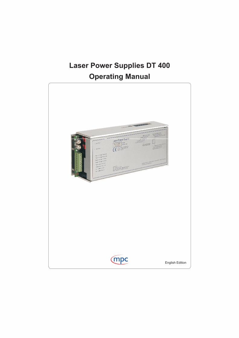
Laser Power Supplies DT 400
Operating Manual
English Edition
Page 1Release 1.0 2007 © Messtec Power Converter GmbH www.laserdriver.eu
Laser Power Supplies DT 400m c
Temperature Sensor KTY 11-5
Shut Down Active High
Operating Mode Auto On
Reference Voltage
PT 1000
Low
On/Off
Diode Current Limit
TEC Voltage Limit
Temperature Interlock
Temperature Set Point
141
Su
pp
lyV
olta
ge
Dio
de
Unit
Su
pp
lyV
olta
ge
Dio
de
Unit
Su
pply
Vo
ltag
eT
EC
Unit
Su
pply
Vo
ltag
eT
EC
Unit
Th
erm
oe
lectric
alC
oo
ler
Th
erm
oe
lectric
alC
oo
ler
Te
mpe
ratu
reS
en
so
r
Te
mpe
ratu
reS
en
so
r
Lase
rD
iod
e
Lase
rD
iod
e
+--++- -+
CA
UT
ION
Do
no
tre
mo
ve
cove
rN
ou
se
rse
rvic
ea
ble
co
mp
on
en
tsin
sid
eR
efe
rserv
icin
gto
qua
lified
pe
rso
nn
el
Me
sste
cP
ow
er
Co
nve
rter
Gm
bH
Gru
be
41
D-
82
37
7P
en
zbe
rgw
ww
.lase
rpow
ers
up
ply.e
u
Re
fere
nce
Vo
ltag
e
Dio
de
Cu
rren
tL
imit
TE
CV
olta
ge
Lim
it
Tem
pera
ture
Inte
rlock
Tem
pera
ture
Se
tP
oin
t
Te
mp
era
ture
Se
nso
rP
T1
00
0
Shu
tD
ow
nA
ctiv
eH
igh
Shu
tD
ow
nA
ctiv
eL
ow
Te
mp
era
ture
Se
nso
rK
TY
11-5
Op
era
ting
Mo
de
On/O
ff
Op
era
ting
Mo
de
Au
toO
n
Te
mp
era
ture
Se
nso
r
Te
mp
era
ture
Se
nso
r
Th
erm
oe
lectric
alC
oole
r
Th
erm
oe
lectric
alC
oole
r
Sup
ply
Vo
ltage
TE
CU
nit
Sup
ply
Vo
ltage
TE
CU
nit
Sup
ply
Vo
ltage
Dio
de
Unit
Sup
ply
Vo
ltage
Dio
de
Unit
La
ser
Dio
de
La
ser
Dio
de
La
se
rP
ow
er
Su
pp
ly
Ge
rma
nP
ate
nt
DE
19
70
01
00
C2
Eu
rop
ea
nP
ate
nt
EP
08
52
42
2B
1M
ad
ein
Ge
rma
ny
Mo
del
Mo
delC
od
e
Index of contents Page
Safety instructions .......................................................................................... 3
DT 400 Description ......................................................................................... 4 - 6
DT 400 - Specification .................................................................................... 7 - 13
DT 400 - General Instructions ........................................................................ 14 - 15
DT 400 - Applications 1 - 14 ........................................................................... 16 - 39
DT 400 - Terminals ......................................................................................... 40
DT 400 - Dimensions ...................................................................................... 41
Control Panels ................................................................................................ 42 - 46
Interlock Unit ................................................................................................... 47 - 50
Control Interface - General Information .......................................................... 51 -55
Control Interface - Control Port ....................................................................... 56 - 59
Control Interface - RS 232 Port ...................................................................... 60 - 96
Control Interface - System Software - Set Up ................................................ 61 -64
Control Interface - System Software - RS 232 Control ................................... 65
Control Interface - System Software - RS 232 Software Protocol................... 66 - 96
Ordering Information ....................................................................................... 97
Laser Power Supplies DT 400
Page 2
m c
Release 1.0 2007 © Messtec Power Converter GmbH www.laserdriver.eu
Safety Instructions
The DT 400 is suitable for supplying laser diodes with a constant current and for supplying peltierelements with a constant voltage.The device is not suitabel for supplying loads which generate a electromotive force of more than30 V.
The lines for the supply voltage must have a cross-section of 2.5 qmm, use sleeves.The lines for the peltier elements must have a cross-section of 1.5 qmm, use sleeves.The lines for the laser diodes must have a cross-section of 6 qmm, use ring terminals.Do not use a crimping tool which does not fit. This increases transition resistance and may causea cable fire.In any case of doubtful crimping, additional soldering is required. Take care that the ring terminalsare free of solder at the screws and at the connection bolts.Use galvanized screws M5 x 8 and galvanized spring washers M5.
Take care of correct input wiring, the device has no inverse-polarity protection. Wrong polarity maydamage the device.
Take care of correct wiring of the laser diodes. Wrong polarity will damage the diodes.
Never disconnect the output lines for the laser diodes during operating.This may generate a dangerous electric arc which can lead to skin burns or to fire.
The DT 400 is cooled by a fan. Air is drawn in at the front side near the terminals and is blown outat the rear side.In an industrial environment with conductive dust, air filtering is required.
Put the device out of operation if it has visible damages or if it doesn't work properly.
Release 1.0 2007 © Messtec Power Converter GmbH www.laserdriver.eu
Laser Power Supplies DT 400m c
Page 3
Description
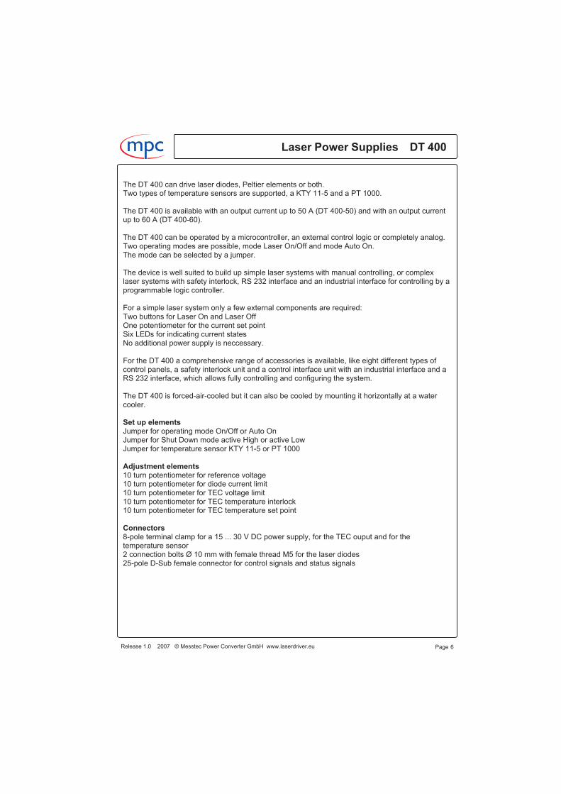
The DT 400 is a high-precision laser diode driver and a full bridge TEC driver with temperaturecontroller and control logic utilizing Messtec's patented power switch technology.This technology has a lot of advantages and is particularly suited for driving laser diodes.It offers high accuracy and current stability, a excellent dynamic performance, a high outputimpedance and low electromagnetic interference.No current overschoot or ringing arise when altering output current or load impedance abruptly.
Overshooting and ringing is very dangerous for laser diodes and it is the most dreaded thing inoperating expensive laser diodes.
Fig. 1 shows the step response of a conventional laser driver at a curent set point step of0 ... 100 %. There is excessive overcurrent and ringing which may damage the laser diodes.
Fig. 2 shows the step response of the DT 400 at a current set point step of 0 ... 100 %, there is noovershoot or ringing, the characteristic is nearly perfect.
Laser Power Supplies DT 400m c
Release 1.0 2007 © Messtec Power Converter GmbH www.laserdriver.eu Page 4
Fig. 2
Tek 11401 DIGITIZING OSCILLOSCOPE
50 A
500 us/Div
Fig. 1
50 A
Tek 11401 DIGITIZING OSCILLOSCOPE
500 us/Div

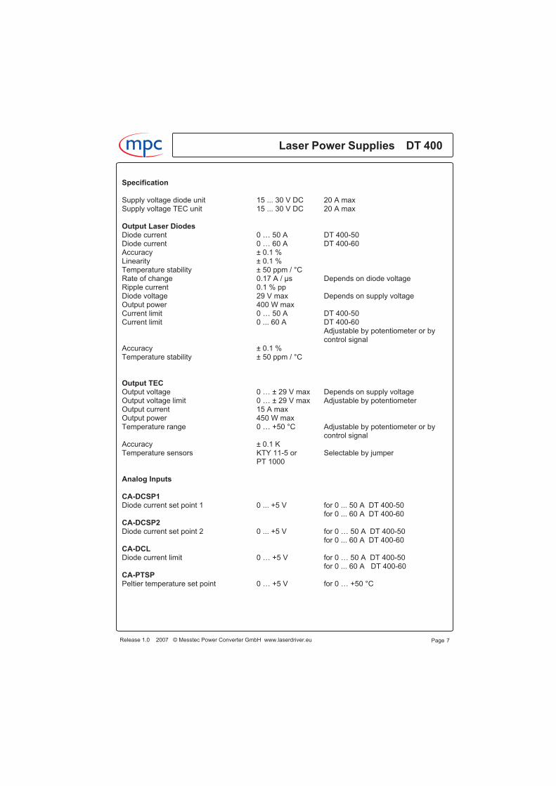
A further major property is the dynamic output impedance which has significant effects to thediode current if load impedance alters abruptly.
For example if there is a loose contact at the output lines and the output is open circuit, the driversoutput voltage will increase to its maximum value because of its characteristic to inject current.If the contact will be closed and you have a conventional laser driver with low dynamic outputimpedance, excessive overcurrent will damage the laser diodes.
The same happens, if you have stacked diodes and one of its emitters will getting short circuit.The load impedance will alter abruptly at this moment and excessive overcurrent will damage thecomplete stack.
Different from a convential laser driver, the DT 400 responds in this case absolutely reliable andno overcurrent occures.
Fig. 3 shows the response of a convential laser diode driver at a nominal output current of 50 A, ifload impedance is changed abruptly to lower values.
Fig. 4 shows the response of the DT 400 at the same conditions, the diode current keepsconstant.
Release 1.0 2007 © Messtec Power Converter GmbH www.laserdriver.eu
Laser Power Supplies DT 400m c
Page 5
Fig. 4
1 µs/Div
Tek 11403 DIGITIZING OSCILLOSCOPE
50 A
150 A
250 A
Fig. 3
Tek 11401 DIGITIZING OSCILLOSCOPE
50 A
1 us/Div
250 A
150 A
The DT 400 can drive laser diodes, Peltier elements or both.Two types of temperature sensors are supported, a KTY 11-5 and a PT 1000.
The DT 400 is available with an output current up to 50 A (DT 400-50) and with an output currentup to 60 A (DT 400-60).
The DT 400 can be operated by a microcontroller, an external control logic or completely analog.Two operating modes are possible, mode Laser On/Off and mode Auto On.The mode can be selected by a jumper.
The device is well suited to build up simple laser systems with manual controlling, or complexlaser systems with safety interlock, RS 232 interface and an industrial interface for controlling by aprogrammable logic controller.
For a simple laser system only a few external components are required:Two buttons for Laser On and Laser OffOne potentiometer for the current set pointSix LEDs for indicating current statesNo additional power supply is neccessary.
For the DT 400 a comprehensive range of accessories is available, like eight different types ofcontrol panels, a safety interlock unit and a control interface unit with an industrial interface and aRS 232 interface, which allows fully controlling and configuring the system.
The DT 400 is forced-air-cooled but it can also be cooled by mounting it horizontally at a watercooler.
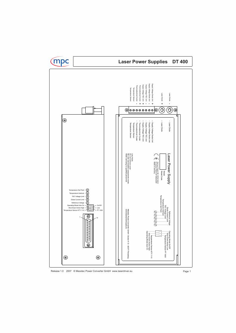
Set up elementsJumper for operating mode On/Off or Auto OnJumper for Shut Down mode active High or active LowJumper for temperature sensor KTY 11-5 or PT 1000
Adjustment elements10 turn potentiometer for reference voltage10 turn potentiometer for diode current limit10 turn potentiometer for TEC voltage limit10 turn potentiometer for TEC temperature interlock10 turn potentiometer for TEC temperature set point
Connectors8-pole terminal clamp for a 15 ... 30 V DC power supply, for the TEC ouput and for thetemperature sensor2 connection bolts Ø 10 mm with female thread M5 for the laser diodes25-pole D-Sub female connector for control signals and status signals
Laser Power Supplies DT 400m c
Release 1.0 2007 © Messtec Power Converter GmbH www.laserdriver.eu Page 6
Specification
Supply voltage diode unit 15 ... 30 V DC 20 A maxSupply voltage TEC unit 15 ... 30 V DC 20 A max
Output Laser DiodesDiode current 0 … 50 A DT 400-50Diode current 0 … 60 A DT 400-60Accuracy ± 0.1 %Linearity ± 0.1 %Temperature stability ± 50 ppm / °CRate of change 0.17 A / µs Depends on diode voltageRipple current 0.1 % ppDiode voltage 29 V max Depends on supply voltageOutput power 400 W maxCurrent limit 0 … 50 A DT 400-50Current limit 0 ... 60 A DT 400-60
Adjustable by potentiometer or bycontrol signal
Accuracy ± 0.1 %Temperature stability ± 50 ppm / °C
Output TECOutput voltage 0 … ± 29 V max Depends on supply voltageOutput voltage limit 0 … ± 29 V max Adjustable by potentiometerOutput current 15 A maxOutput power 450 W maxTemperature range 0 … +50 °C Adjustable by potentiometer or by
control signalAccuracy ± 0.1 KTemperature sensors KTY 11-5 or Selectable by jumper
PT 1000
Analog Inputs
CA-DCSP1Diode current set point 1 0 ... +5 V for 0 ... 50 A DT 400-50
for 0 ... 60 A DT 400-60CA-DCSP2Diode current set point 2 0 ... +5 V for 0 … 50 A DT 400-50
for 0 ... 60 A DT 400-60CA-DCLDiode current limit 0 … +5 V for 0 … 50 A DT 400-50
for 0 ... 60 A DT 400-60CA-PTSPPeltier temperature set point 0 … +5 V for 0 … +50 °C
Release 1.0 2007 © Messtec Power Converter GmbH www.laserdriver.eu
Laser Power Supplies DT 400m c
Page 7
Analog Outputs
SA-DCACTDiode current actual 0 … +5 V for 0 … 50 ASA-DCSPLIMDiode current set point limited 0 … +5 V for 0 … 50 ASA-DVACTDiode voltage 0 ... +5 V for 0 … 25 VSA-PTACTPeltier temperature actual 0 … +5 V for 0 … +50 °CREFReference voltage +5 V 2 mA maxREFVARReference voltage adjustable 0 … +5 V Adjustable by potentiometer
2 mA maxAUX+5VAuxiliary voltage +5 V +5.1 V Current up to 200 mAAUX+15VAuxiliary voltage +15 V +15 V Current up to 100 mAAUX-15VAuxiliary voltage -15 V -15 V Current up to 100 mA
Digital Inputs
CD-DCONDiode Current On + 5 V Connected to GND for 1 ms switches
on (On/Off mode)CD-DCOFFDiode Current Off + 5 V Connected to GND for 1 ms turns off
(On/Off mode)CD-DCSDDiode Current Shut Down TTL Active Low or High, selectable by
jumperCD-PSDPeltier Shut Down TTL High turns the TEC voltage off
Digital Outputs
SD-READYReady TTL Open emitter, High if there are no
errorsSD-DCONDiode Current On TTL Open emitter, High if the diode
current is switched onSD-DCSDDiode Current Shut Down TTL Open emitter, High if the diode
current Shut Down is active
Laser Power Supplies DT 400m c
Release 1.0 2007 © Messtec Power Converter GmbH www.laserdriver.eu Page 8
SD-PTLPeltier Temperature Low TTL Open emitter, High if the peltier
temperature is lowSD-PTHPeltier Temperature High TTL Open emitter, High if the peltier
temperature is highSD-PTIPeltier Temperature Interlock TTL Open emitter, High if the peltier
temperature exceeds the maximumallowed temperature.The system is turned off.The threshold value is adjustable bypotentiometer.
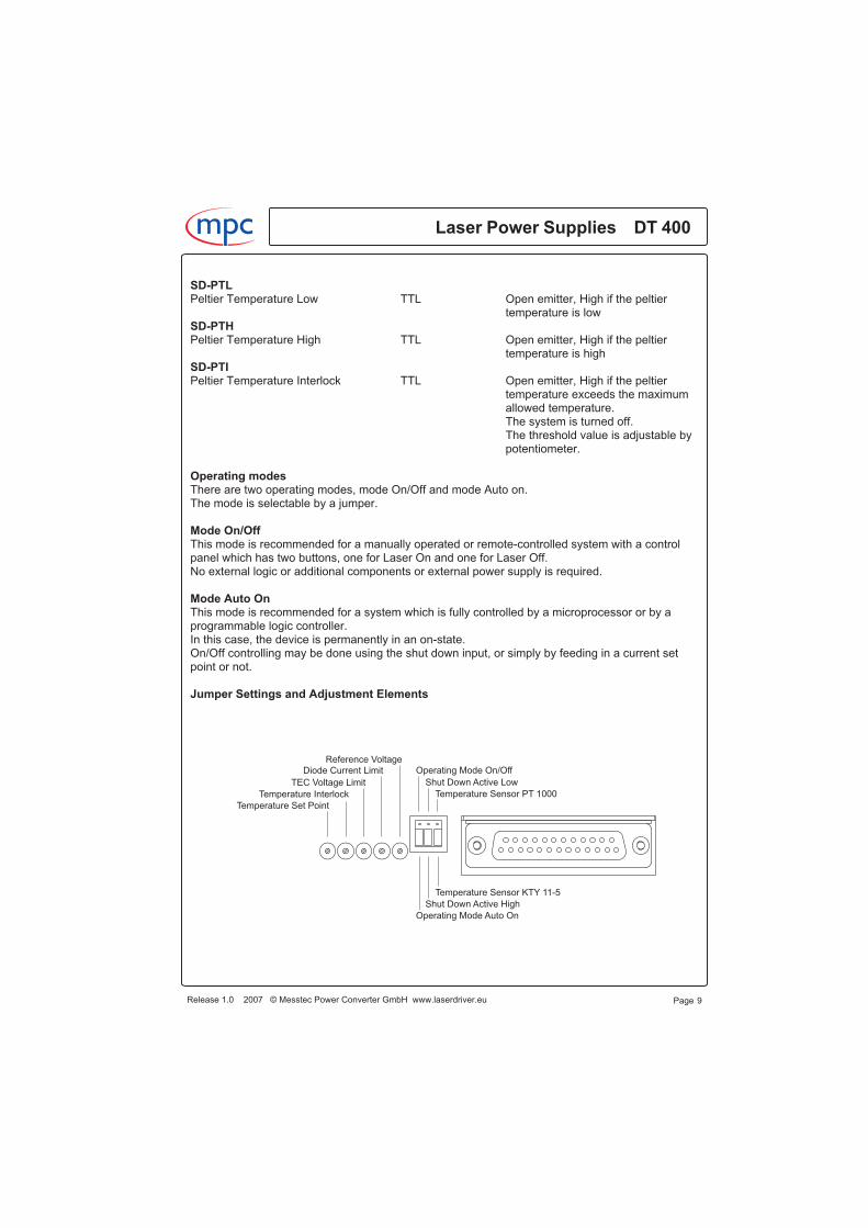
Operating modesThere are two operating modes, mode On/Off and mode Auto on.The mode is selectable by a jumper.
Mode On/OffThis mode is recommended for a manually operated or remote-controlled system with a controlpanel which has two buttons, one for Laser On and one for Laser Off.No external logic or additional components or external power supply is required.
Mode Auto OnThis mode is recommended for a system which is fully controlled by a microprocessor or by aprogrammable logic controller.In this case, the device is permanently in an on-state.On/Off controlling may be done using the shut down input, or simply by feeding in a current setpoint or not.
Jumper Settings and Adjustment Elements
Release 1.0 2007 © Messtec Power Converter GmbH www.laserdriver.eu
Laser Power Supplies DT 400m c
Page 9
Temperature Sensor KTY 11-5
Shut Down Active High
Operating Mode Auto On
Temperature Sensor PT 1000
Shut Down Active Low
Operating Mode On/OffReference Voltage
Diode Current Limit
TEC Voltage Limit
Temperature Interlock
Temperature Set Point
m c
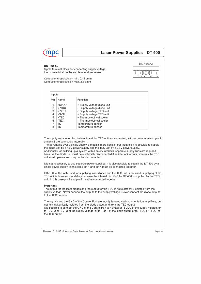
DC Port X28 pole terminal block, for connecting supply voltage,thermo-electrical cooler and temperature sensor.
Conductor cross section min. 0.14 qmmConductor cross section max. 2.5 qmm
The supply voltage for the diode unit and the TEC unit are separated, with a common minus, pin 2and pin 3 are connected internally.The advantage over a single supply is that it is more flexible. For instance it is possible to supplythe diode unit by a 15 V power supply and the TEC unit by a 24 V power supply.Additionally for building up a system with a safety interlock, separate supply lines are requiredbecause the diode unit must be electrically disconnected if an interlock occurs, whereas the TECunit must operate and may not be disconnected.
It is not neccessary to use separate power supplies, it is also possible to supply the DT 400 by asingle power supply. In this case pin 1 and pin 4 must be connected together.
If the DT 400 is only used for supplying laser diodes and the TEC unit is not used, supplying of theTEC unit is however mandatory because the internal circuit of the DT 400 is supplied by the TECunit. In this case pin 1 and pin 4 must be connected together.
ImportantThe output for the laser diodes and the output for the TEC is not electrically isolated from thesupply voltage. Never connect the outputs to the supply voltage. Never connect the diode outputsto the TEC outputs.
The signals and the GND of the Control Port are mostly isolated via instrumentation amplifiers, butnot fully galvanically isolated from the diode output and from the TEC output .It is possible to connect the GND of the Control Port to +SVDU or -SVDU of the supply voltage, orto +SVTU or -SVTU of the supply voltage, or to + or - of the diode output or to +TEC or -TEC ofthe TEC output.
Page 10
1 2 3 4 5 6 7 8
DC Port X2
Inputs
Pin Name Function
12345678
+SVDU-SVDU-SVTU+SVTU+TEC-TECTSTS
+ Supply voltage diode unit- Supply voltage diode unit- Supply voltage TEC unit+ Supply voltage TEC unit+ Thermoelectrical cooler- Thermoelectrical coolerTemperature sensorTemperature sensor
Laser Power Supplies DT 400m c
Release 1.0 2007 © Messtec Power Converter GmbH www.laserdriver.eu
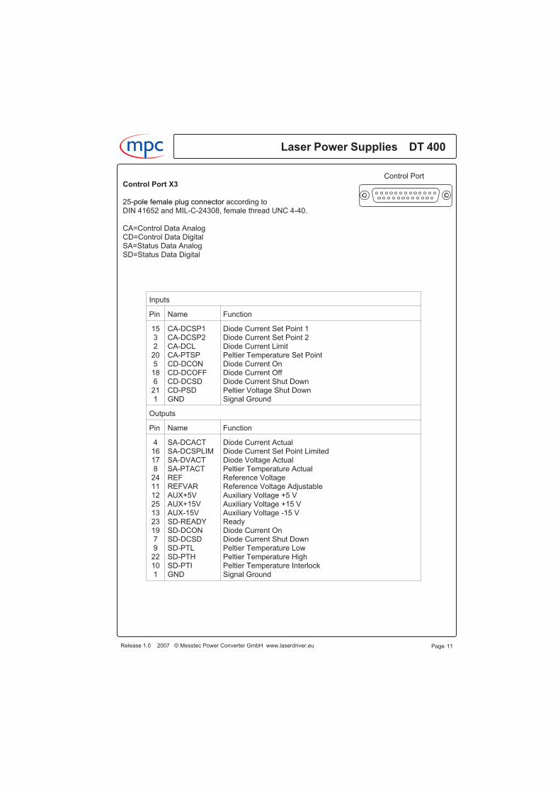
Control Port X3
25-pole female plug connector according toDIN 41652 and MIL-C-24308, female thread UNC 4-40.
CA=Control Data AnalogCD=Control Data DigitalSA=Status Data AnalogSD=Status Data Digital
Release 1.0 2007 © Messtec Power Converter GmbH www.laserdriver.eu
Laser Power Supplies DT 400m c
Page 11
Control Port
Inputs
Pin Name Function
1532205186211
CA-DCSP1CA-DCSP2CA-DCLCA-PTSPCD-DCONCD-DCOFFCD-DCSDCD-PSDGND
Diode Current Set Point 1Diode Current Set Point 2Diode Current LimitPeltier Temperature Set PointDiode Current OnDiode Current OffDiode Current Shut DownPeltier Voltage Shut DownSignal Ground
Outputs
Pin Name Function
416178241112251323197922101
SA-DCACTSA-DCSPLIMSA-DVACTSA-PTACTREFREFVARAUX+5VAUX+15VAUX-15VSD-READYSD-DCONSD-DCSDSD-PTLSD-PTHSD-PTIGND
Diode Current ActualDiode Current Set Point LimitedDiode Voltage ActualPeltier Temperature ActualReference VoltageReference Voltage AdjustableAuxiliary Voltage +5 VAuxiliary Voltage +15 VAuxiliary Voltage -15 VReadyDiode Current OnDiode Current Shut DownPeltier Temperature LowPeltier Temperature HighPeltier Temperature InterlockSignal Ground
Signal description
CA-DCSP1Control Analog - Diode Current Set Point 1Analog input 0 ... +5.000 V, corresponds to a diode current of 0 ... 50.00A.
CA-DCSP2Control Analog - Diode Current Set Point 2Analog input 0 ... +5.000 V, corresponds to a diode current of 0 ... 50.00A.
Diode Current Set Point 1 and Diode Current Set Point 2 will be added internally and generate theeffective current set point.A current set point with negative sign acts subtracting.
CA-DCLControl Analog - Diode Current LimitAnalog input 0 ... +5.000 V, corresponds to a diode current limit of 0 ... 50.00 A.
There are four possibilities for diode current limiting, limiting by CA-DCL, by memory, by RS 232 orby the diode current limit potentiometer.If limiting by CA-DCL or by memory or by RS 232 is selected, the current limit potentiometer has tobe turned clockwise to its maximum value.If limiting by the diode current limit potentiometer is selected, the CA-DCL input must beconnected to the REF output (+5.000 V).
CA-PTSPControl Analog - Peltier Temperature Set PointAnalog input 0 ... +5.000 V, corresponds to a peltier temperature of 0 ... + 50.00 °C.
There are four possibilities for a temperature set point, by CA-PTSP, by memory, by RS 232 or bythe temperature set point potentiometer.If a temperature set point by CA-PTSP or by memory or by RS 232 is selected, the temperatureset point potentiometer has to be turned counterclockwise to its minimum value.If a temperature set point by the temperature set point potentiometer is selected, the CA-PTSPinput has to be left open.
The value of the CA-PTSP signal and the value which comes from the temperature set pointpotentiometer will be added internally and generate the effective temperature set point.It is also possible, to combine both values e.g. giving a temperature set point of 20 °C by thepotentiometer and adding or subtracting 10 °C by a value of ±1 V at the CA-PTSP input.
SA-DCACTStatus Analog - Diode Current ActualAnalog ouput 0 ... 5.000 V, corresponds to a diode current of 0 ... 50 A.
SA-DCSPLIMStatus Analog - Diode Current Set Point LimitedAnalog output 0 ... 5.000 V, reflects the diode current set point, limited by the diode current limitvalue of CA-DCL or by the value of the current limit potentiometer.
Laser Power Supplies DT 400m c
Release 1.0 2007 © Messtec Power Converter GmbH www.laserdriver.eu Page 12
Control Port

SA-DVACTStatus Analog - Diode Voltage ActualAnalog output 0 ... +5.000 V, corresponds to adiode voltage of 0 ... +25.00 V.Reflects the actual diode voltage.
SA-PTACTStatus Analog - Peltier Temperature ActualAnalog output 0 ... +5.000 V, corresponds to a peltier temperature of 0 ... +50,00 °C.Reflects the actual peltier temperature.
REFAnalog output +5.000 V
REFVARAnalog output 0 ... +5.000 V, adjustable by the reference voltage potentiometer.
AUX+5VOutput +5.1 V, for supplying external components.Maximum allowable current: 200 mA.
AUX+15VOutput +15 V approximately, for supplying external components.Maximum allowable current: 100 mA.
AUX-15VOutput -15 V approximately, for supplying external components.Maximum allowable current: 100 mA.
CD-DCONControl Digital - Diode Current OnDigital TTL input, High if left open.In the operating mode On/Off the input acts in the following way:If the input is pulled to GND for approximately 1 ms, the diode current will be switched on.The diode current remains switched on until a CD-DCOFF signal turns off.In the operating mode Auto On, the input is without effect.
CD-DCOFFControl Digital - Diode Current OffDigital TTL input, High if left open.In the operating mode On/Off the input acts in the following way:If diode current is switched on and if the input is pulled to GND for approximately 1 ms, the diodecurrent will be turned off.The diode current remains in an off-stae until a CD-DCON signal turns on.In both operating modes the CD-DCOFF input also acts as a system reset if an error has occured.In this case the system will be resetted if the input is pulled to GND for approximately 1 ms.
CD-DCSDControl Digital - Diode Current Shut DownDigital TTL input, active High or active Low, selectable by a jumper.Disables or enables diode current, useful for pulsing.
Release 1.0 2007 © Messtec Power Converter GmbH www.laserdriver.eu
Laser Power Supplies DT 400m c
Page 13
Control Port
General Instructions
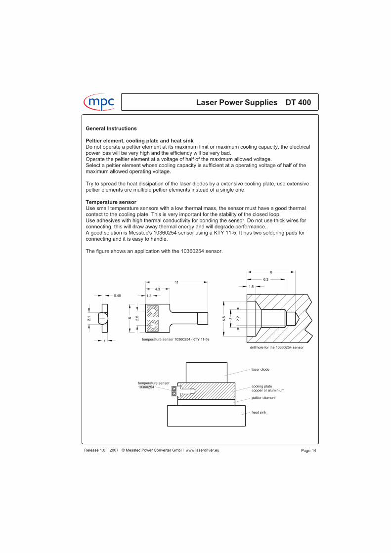
Peltier element, cooling plate and heat sinkDo not operate a peltier element at its maximum limit or maximum cooling capacity, the electricalpower loss will be very high and the efficiency will be very bad.Operate the peltier element at a voltage of half of the maximum allowed voltage.Select a peltier element whose cooling capacity is sufficient at a operating voltage of half of themaximum allowed operating voltage.
Try to spread the heat dissipation of the laser diodes by a extensive cooling plate, use extensivepeltier elements ore multiple peltier elements instead of a single one.
Temperature sensorUse small temperature sensors with a low thermal mass, the sensor must have a good thermalcontact to the cooling plate. This is very important for the stability of the closed loop.Use adhesives with high thermal conductivity for bonding the sensor. Do not use thick wires forconnecting, this will draw away thermal energy and will degrade performance.A good solution is Messtec's 10360254 sensor using a KTY 11-5. It has two soldering pads forconnecting and it is easy to handle.
The figure shows an application with the 10360254 sensor.
Laser Power Supplies DT 400m c
Release 1.0 2007 © Messtec Power Converter GmbH www.laserdriver.eu Page 14
laser diode
temperature sensor10360254 cooling plate
copper or aluminium
peltier element
heat sink
8
6.3
1.5
2.2
5.8 3
drill hole for the 10360254 sensor
11
4.3
1.30.45
2.1
1
5
2.5
temperature sensor 10360254 (KTY 11-5)
General Instructions
TEC voltage limitAdjust the TEC voltage limit before connecting a peltier element.Connect a temperature sensor, either Messtec's 10360254 (KTY 11-5), a conventional KTY 11-5or a PT 1000 to pin 7 and pin 8 of X2.Pay attention to the proper jumper setting.
You can also take a 1000 � resistor instead of a temperature sensor, in this case set the jumper toPT 1000.Connect a voltmeter to the TEC ouput and turn the DT 400 on.Adjust TEC voltage to the maximum allowed value of your peltier element.
Temperature interlockDo not adjust the trigger point very close to the operating temperature. Consider that in mostcases a thermal overshoot will occur if the system is turned on.
Diode current and diode current limitDo not connect laser diodes if it is the first time you put a DT 400 into operation.Use a short circuit instead of laser diodes, connect the +laser diode output to the -laser diodeoutput.Connect a voltmeter to the SA-DCACT output (Diode Current Actual) and to GND of the controlport. Turn on the DT 400 and feed in a current set point of 0 ... 5 V at the CA-DCSP1 input.Watch the voltmeter, it reflects the diode current, in this case it reflects the current which flowsthrough the short circuit. The reading value must be identical to the current set point.For instance if you have a DT 400-50 and the current set point is 5 V, the reading value must be5 V, reflecting a current of 50 A through the short circuit.
Adjust the diode current limit potentiometer.Example: You have a DT 400-60 and you would like to limit the diode current to a value of 55 A.Feed in a current set point of 5 V, voltmeter reading is now 5 V, reflecting 60 A current.Turn the diode current limit potentiometer counterclockwise to a reading value of 4.58 V, reflecting55 A current.
Release 1.0 2007 © Messtec Power Converter GmbH www.laserdriver.eu
Laser Power Supplies DT 400m c
Page 15
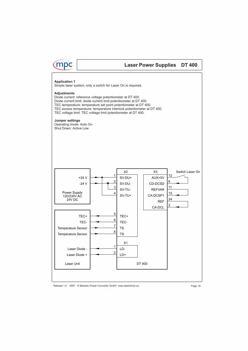
Application 1Simple laser system, only a switch for Laser On is required.
AdjustmentsDiode current: reference voltage potentiometer at DT 400.Diode current limit: diode current limit potentiometer at DT 400.TEC temperature: temperature set point potentiometer at DT 400.TEC excess temperature: temperature interlock potentiometer at DT 400.TEC voltage limit: TEC voltage limit potentiometer at DT 400.
Jumper settingsOperating mode: Auto OnShut Down: Active Low
Laser Power Supplies DT 400m c
Release 1.0 2007 © Messtec Power Converter GmbH www.laserdriver.eu Page 16
24V DC120/230V ACPower Supply
Laser Unit
X1
X3X2
Temperature Sensor
Temperature Sensor
TEC-
Laser Diode +
Laser Diode -
TEC+
-24 V
+24 V
LD+
LD-
TS
TS
TEC-
TEC+
SV-TU+
SV-TU-
SV-DU-
SV-DU+
Switch Laser On
REF
CA-DCL
CA-DCSP1
REFVAR11
15
24
2
1
2
3
4
5
6
7
8
1
2
6CD-DCSD
AUX+5V12
DT 400
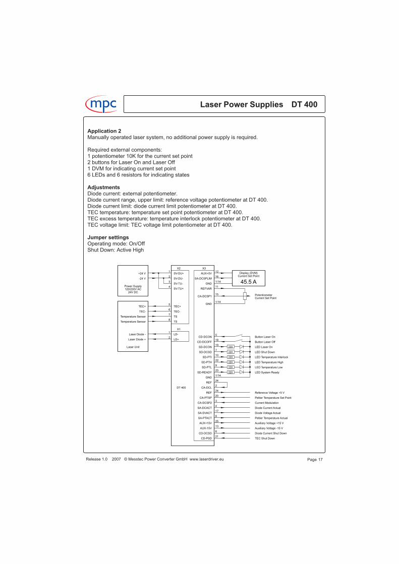
Application 2Manually operated laser system, no additional power supply is required.
Required external components:1 potentiometer 10K for the current set point2 buttons for Laser On and Laser Off1 DVM for indicating current set point6 LEDs and 6 resistors for indicating states
AdjustmentsDiode current: external potentiometer.Diode current range, upper limit: reference voltage potentiometer at DT 400.Diode current limit: diode current limit potentiometer at DT 400.TEC temperature: temperature set point potentiometer at DT 400.TEC excess temperature: temperature interlock potentiometer at DT 400.TEC voltage limit: TEC voltage limit potentiometer at DT 400.
Jumper settingsOperating mode: On/OffShut Down: Active High
Release 1.0 2007 © Messtec Power Converter GmbH www.laserdriver.eu
Laser Power Supplies DT 400m c
Page 17
45.5 A
Current Set PointDisplay (DVM)
Current Set PointPotentiometer
220
220
220
220
220
220
LED System Ready
LED Temperature Low
LED Temperature High
LED Shut Down
TEC Shut Down
Diode Current Shut Down
Peltier Temperature Actual
Diode Voltage Actual
Diode Current Actual
DT 400
24V DC120/230V ACPower Supply
Laser Unit
X1
X3X2
Temperature Sensor
Temperature Sensor
TEC-
Laser Diode +
Laser Diode -
TEC+
-24 V
+24 V
LD+
LD-
TS
TS
TEC-
TEC+
SV-TU+
SV-TU-
SV-DU-
SV-DU+
LED Temperature Interlock
LED Laser On
Button Laser Off
Button Laser On
AUX-15V
AUX+15V
REF
CD-PSD
CD-DCSD
SA-PTACT
SA-DVACT
SA-DCACT
CA-DCL
CA-DCSP2
GND
SD-READY
SD-PTL
SD-PTH
SD-PTI
SD-DCSD
SD-DCON
CD-DCOFF
CD-DCON
REF
GND
CA-DCSP1
REFVAR
GND
CA-PTSP
SA-DCSPLIM
AUX+5V
Current Modulation
Auxiliary Voltage +15 V
Auxiliary Voltage -15 V
12
16
1/14
11
15
1/14
24
20
5
18
19
7
10
22
9
23
1/14
24
2
3
4
17
8
25
13
6
21
1
2
3
4
5
6
7
8
1
2
Peltier Temperature Set Point
Reference Voltage +5 V
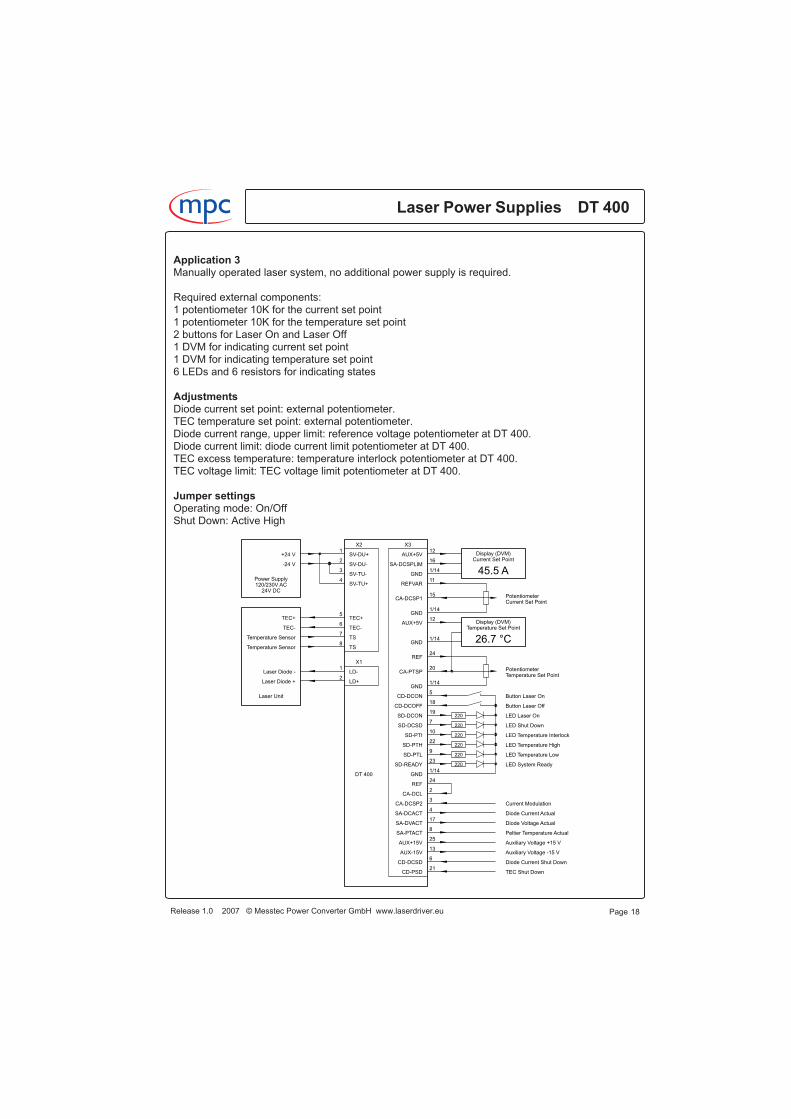
Application 3Manually operated laser system, no additional power supply is required.
Required external components:1 potentiometer 10K for the current set point1 potentiometer 10K for the temperature set point2 buttons for Laser On and Laser Off1 DVM for indicating current set point1 DVM for indicating temperature set point6 LEDs and 6 resistors for indicating states
AdjustmentsDiode current set point: external potentiometer.TEC temperature set point: external potentiometer.Diode current range, upper limit: reference voltage potentiometer at DT 400.Diode current limit: diode current limit potentiometer at DT 400.TEC excess temperature: temperature interlock potentiometer at DT 400.TEC voltage limit: TEC voltage limit potentiometer at DT 400.
Jumper settingsOperating mode: On/OffShut Down: Active High
Laser Power Supplies DT 400m c
Release 1.0 2007 © Messtec Power Converter GmbH www.laserdriver.eu Page 18
26.7 °C
45.5 A
Display (DVM)Temperature Set Point
Current Set PointDisplay (DVM)
PotentiometerTemperature Set Point
Current Set PointPotentiometer
220
220
220
220
220
220
LED System Ready
LED Temperature Low
LED Temperature High
LED Shut Down
TEC Shut Down
Diode Current Shut Down
Peltier Temperature Actual
Diode Voltage Actual
Diode Current Actual
DT 400
24V DC120/230V ACPower Supply
Laser Unit
X1
X3X2
Temperature Sensor
Temperature Sensor
TEC-
Laser Diode +
Laser Diode -
TEC+
-24 V
+24 V
LD+
LD-
TS
TS
TEC-
TEC+
SV-TU+
SV-TU-
SV-DU-
SV-DU+
LED Temperature Interlock
LED Laser On
Button Laser Off
Button Laser On
AUX-15V
AUX+15V
REF
CD-PSD
CD-DCSD
SA-PTACT
SA-DVACT
SA-DCACT
CA-DCL
CA-DCSP2
GND
SD-READY
SD-PTL
SD-PTH
SD-PTI
SD-DCSD
SD-DCON
CD-DCOFF
CD-DCON
GND
REF
GND
CA-DCSP1
REFVAR
GND
AUX+5V
CA-PTSP
GND
SA-DCSPLIM
AUX+5V
Current Modulation
Auxiliary Voltage +15 V
Auxiliary Voltage -15 V
12
16
1/14
11
15
1/14
12
1/14
24
20
1/14
5
18
19
7
10
22
9
23
1/14
24
2
3
4
17
8
25
13
6
21
1
2
3
4
5
6
7
8
1
2
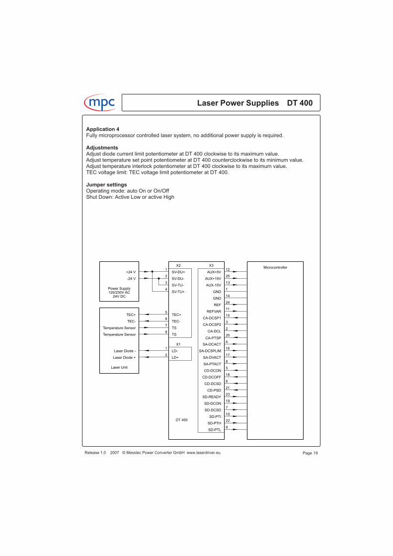
Application 4Fully microprocessor controlled laser system, no additional power supply is required.
AdjustmentsAdjust diode current limit potentiometer at DT 400 clockwise to its maximum value.Adjust temperature set point potentiometer at DT 400 counterclockwise to its minimum value.Adjust temperature interlock potentiometer at DT 400 clockwise to its maximum value.TEC voltage limit: TEC voltage limit potentiometer at DT 400.
Jumper settingsOperating mode: auto On or On/OffShut Down: Active Low or active High
Release 1.0 2007 © Messtec Power Converter GmbH www.laserdriver.eu
Laser Power Supplies DT 400m c
Page 19
DT 400
24V DC120/230V ACPower Supply
Laser Unit
X1
X3X2
Temperature Sensor
Temperature Sensor
TEC-
Laser Diode +
Laser Diode -
TEC+
-24 V
+24 V
LD+
LD-
TS
TS
TEC-
TEC+
SV-TU+
SV-TU-
SV-DU-
SV-DU+ AUX+5V121
2
3
4
5
6
7
8
1
2
25
13
1
14
15
11
24
20
2
3
6
21
23
8
5
18
17
16
4
10
22
9
19
7
AUX+15V
AUX-15V
GND
CA-DCSP1
CA-DCSP2
CA-DCL
CA-PTSP
SA-DCACT
SA-DCSPLIM
SA-DVACT
SA-PTACT
CD-DCON
REFVAR
REF
CD-DCOFF
CD-DCSD
CD-PSD
SD-DCON
SD-DCSD
SD-PTI
SD-PTH
SD-PTL
SD-READY
GND
Microcontroller
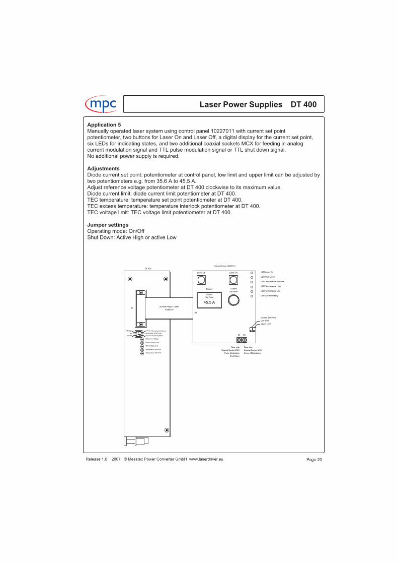
Application 5Manually operated laser system using control panel 10227011 with current set pointpotentiometer, two buttons for Laser On and Laser Off, a digital display for the current set point,six LEDs for indicating states, and two additional coaxial sockets MCX for feeding in analogcurrent modulation signal and TTL pulse modulation signal or TTL shut down signal.No additional power supply is required.
AdjustmentsDiode current set point: potentiometer at control panel, low limit and upper limit can be adjusted bytwo potentiometers e.g. from 35.6 A to 45.5 A.Adjust reference voltage potentiometer at DT 400 clockwise to its maximum value.Diode current limit: diode current limit potentiometer at DT 400.TEC temperature: temperature set point potentiometer at DT 400.TEC excess temperature: temperature interlock potentiometer at DT 400.TEC voltage limit: TEC voltage limit potentiometer at DT 400.
Jumper settingsOperating mode: On/OffShut Down: Active High or active Low
Laser Power Supplies DT 400m c
Release 1.0 2007 © Messtec Power Converter GmbH www.laserdriver.eu Page 20
LED Laser On
LED Temperature Interlock
LED Shut Down
LED Temperature High
LED Temperature Low
LED System Ready
45.5 A
Current
Display
Laser Off Laser On
Current Set Point
Low Limit
Upper Limit
Set Point
Set Point
Current
KTY11-5 Temperature Sensor
Active High Shut Down
Auto On Operating Mode
Reference Voltage
Diode Current Limit
TEC Voltage Limit
Temperature Interlock
Temperature Set Point
PT 1000
Low
On/Off
25 Pole Ribbon Cable
10385338
Control Panel 10227011
DT 400
X3
X1
X3X4
Rear side
Coaxial Socket MCX
Current Modulation
Rear side
Coaxial Socket MCX
Pulse Modulation
Shut Down
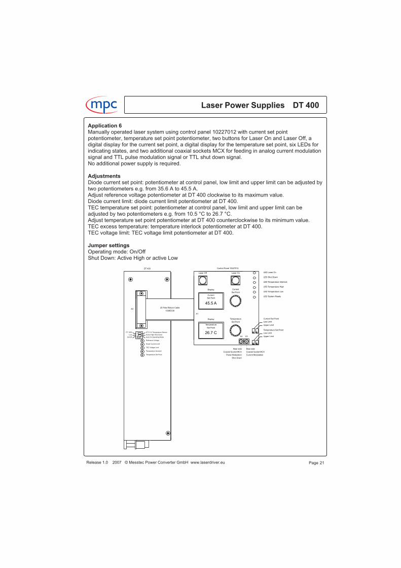
Application 6Manually operated laser system using control panel 10227012 with current set pointpotentiometer, temperature set point potentiometer, two buttons for Laser On and Laser Off, adigital display for the current set point, a digital display for the temperature set point, six LEDs forindicating states, and two additional coaxial sockets MCX for feeding in analog current modulationsignal and TTL pulse modulation signal or TTL shut down signal.No additional power supply is required.
AdjustmentsDiode current set point: potentiometer at control panel, low limit and upper limit can be adjusted bytwo potentiometers e.g. from 35.6 A to 45.5 A.Adjust reference voltage potentiometer at DT 400 clockwise to its maximum value.Diode current limit: diode current limit potentiometer at DT 400.TEC temperature set point: potentiometer at control panel, low limit and upper limit can beadjusted by two potentiometers e.g. from 10.5 °C to 26.7 °C.Adjust temperature set point potentiometer at DT 400 counterclockwise to its minimum value.TEC excess temperature: temperature interlock potentiometer at DT 400.TEC voltage limit: TEC voltage limit potentiometer at DT 400.
Jumper settingsOperating mode: On/OffShut Down: Active High or active Low
Release 1.0 2007 © Messtec Power Converter GmbH www.laserdriver.eu
Laser Power Supplies DT 400m c
Page 21
LED Laser On
LED Temperature Interlock
LED Shut Down
LED Temperature High
LED Temperature Low
LED System Ready
45.5 A
Current
Display
Display
Temperature
26.7 C
Laser Off Laser On
Temperature Current Set Point
Low Limit
Upper Limit
Temperature Set Point
Low Limit
Upper Limit
Set Point
Set Point
Set Point
Set Point
Current
KTY11-5 Temperature Sensor
Active High Shut Down
Auto On Operating Mode
Reference Voltage
Diode Current Limit
TEC Voltage Limit
Temperature Interlock
Temperature Set Point
PT 1000
Low
On/Off
25 Pole Ribbon Cable
10385338
Control Panel 10227012DT 400
X3
X1
X3X4
Rear side
Coaxial Socket MCX
Current Modulation
Rear side
Coaxial Socket MCX
Pulse Modulation
Shut Down
Application 7Manually operated complete laser system utilizing accessories kits.No additional power supply is required.
Front panelKey-operated switch and emergency stop button for the mains voltage.Current set point potentiometer, two buttons for Laser On and Laser Off, a digital display for thecurrent set point and six LEDs for indicating states.
Rear panelConnector for the mains voltage, BNC jack for analog current modulation, BNC jack for TTL pulsemodulation signal or TTL shut down.
AccessoriesPower supply 10870022120/230 V AC 24V/20 A DC
Control panel 10227011with current set point potentiometer, two buttons for Laser On and Laser Off, a digital display forthe current set point, six LEDs for indicating states and two coaxial sockets MCX for feeding inanalog current modulation signal and TTL pulse modulation signal or TTL shut down signal.
Heat sink 10500882for mounting printed circuit board 10360347, peltier elements and laser diodes.
Printed circuit board 10360347with 6 pole terminal clamp and soldering pads for TEC, temperature sensor and pilot laser and5 pole terminal with female thread M5 for the laser diodes.
25 pole ribbon cable 10385338length 350 mm.
AdjustmentsDiode current set point: potentiometer at control panel, low limit and upper limit can be adjusted bytwo potentiometers e.g. from 35.6 A to 45.5 A.Adjust reference voltage potentiometer at DT 400 clockwise to its maximum value.Diode current limit: diode current limit potentiometer at DT 400.TEC temperature set point: temperature set point potentiometer at DT 400.TEC excess temperature: temperature interlock potentiometer at DT 400.TEC voltage limit: TEC voltage limit potentiometer at DT 400.
Jumper settingsOperating mode: On/OffShut Down: Active High
Laser Power Supplies DT 400m c
Release 1.0 2007 © Messtec Power Converter GmbH www.laserdriver.eu Page 22

Application 7
Release 1.0 2007 © Messtec Power Converter GmbH www.laserdriver.eu
Laser Power Supplies DT 400m c
Page 23
Laser On
Shut Down
Temperature Interlock
Temperature High
Temperature Low
System Ready
126
26 pole
25
po
le
13
1
+2
4V
+2
4V
+2
4V
+2
4V
-24
V
-24
V
-24
V
-24
V
PENL
Emergency Stop
Key Switch
PT 1000
Low
On/Off
Temperature Sensor KTY 11-5
Shut Down Active High
Temperature Set Point
Operating Mode Auto On
Reference Voltage
Diode Current Limit
TEC Voltage Limit
Temperature Interlock
+S
VD
iode
Un
it
-SV
Dio
de
Un
it
-SV
TE
CU
nit
+S
VT
EC
Un
it
-TE
C
+T
EC
Te
mp
era
ture
Se
nso
r
Te
mp
era
ture
Se
nso
r
Laser Diode +
Laser Diode -
Te
mp
era
ture
Se
nso
r
Te
mp
era
ture
Se
nso
r
+T
EC
-TE
C
-Pi lo
tL
ase
r
+P
ilot
La
se
r
X3X4
Current Set Point
Low Limit
Upper Limit
Current
Off On
-TE
C
+T
EC
Te
mp
era
ture
Se
nso
r
Te
mp
era
ture
Se
nso
r
-Pi lo
tL
ase
r
+P
ilot
La
se
r
+L
ase
rD
iod
e
-Laser
Dio
de
+L
ase
rD
iod
e
10500882
Heat Sink
10360347
Printed Circuit Board
DT 400
Power Supply 24V
Front Panel
Rear Panel
Control Panel
10227011
Power Entry Module
Fan for heat sink
10500882
X3
25 pole ribbon cable
10385338
BNC jack
Pulse Modulation
Shut Down
BNC jack
Current Modulation
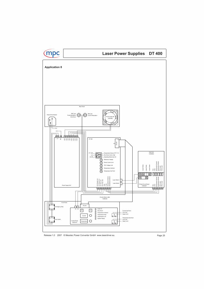
Application 8Manually operated complete laser system utilizing accessories kits.No additional power supply is required.
Front panelKey-operated switch and emergency stop button for the mains voltage.Current set point potentiometer, temperature set point potentiometer, two buttons for Laser Onand Laser Off, a digital display for the current set point, a digital display for the temperature setpoint and six LEDs for indicating states.
Rear panelConnector for the mains voltage, BNC jack for analog current modulation, BNC jack for TTL pulsemodulation signal or TTL shut down.
AccessoriesPower supply 10870022120/230 V AC 24V/20 A DC
Control panel 10227012with current set point potentiometer, temperature set point potentiometer, two buttons for Laser Onand Laser Off, a digital display for the current set point, a digital display for the temperature setpoint, six LEDs for indicating states and two coaxial sockets MCX for feeding in analog currentmodulation signal and TTL pulse modulation signal or TTL shut down signal.
Heat sink 10500882for mounting printed circuit board 10360347, peltier elements and laser diodes.
Printed circuit board 10360347with 6 pole terminal clamp and soldering pads for TEC, temperature sensor and pilot laser and5 pole terminal with female thread M5 for the laser diodes.
25 pole ribbon cable 10385338length 350 mm.
AdjustmentsDiode current set point: potentiometer at control panel, low limit and upper limit can be adjusted bytwo potentiometers e.g. from 35.6 A to 45.5 A.Adjust reference voltage potentiometer at DT 400 clockwise to its maximum value.Diode current limit: diode current limit potentiometer at DT 400.TEC temperature set point: potentiometer at control panel, low limit and upper limit can beadjusted by two potentiometers e.g. from 10.5 °C to 26.7 °C.Adjust temperature set point potentiometer at DT 400 counterclockwise to its minimum value.TEC excess temperature: temperature interlock potentiometer at DT 400.TEC voltage limit: TEC voltage limit potentiometer at DT 400.
Jumper settingsOperating mode: On/OffShut Down: Active High
Laser Power Supplies DT 400m c
Release 1.0 2007 © Messtec Power Converter GmbH www.laserdriver.eu Page 24
Application 8
Release 1.0 2007 © Messtec Power Converter GmbH www.laserdriver.eu
Laser Power Supplies DT 400m c
Page 25
Laser On
Shut Down
Temperature Interlock
Temperature High
Temperature Low
System Ready
126
26 pole
25
po
le
13
1
+2
4V
+2
4V
+2
4V
+2
4V
-24
V
-24
V
-24
V
-24
V
PENL
Emergency Stop
Key Switch
PT 1000
Low
On/Off
Temperature Sensor KTY 11-5
Shut Down Active High
Temperature Set Point
Operating Mode Auto On
Reference Voltage
Diode Current Limit
TEC Voltage Limit
Temperature Interlock
+S
VD
iode
Un
it
-SV
Dio
de
Un
it
-SV
TE
CU
nit
+S
VT
EC
Un
it
-TE
C
+T
EC
Te
mp
era
ture
Se
nso
r
Te
mp
era
ture
Se
nso
r
Laser Diode +
Laser Diode -
Te
mp
era
ture
Se
nso
r
Te
mp
era
ture
Se
nso
r
+T
EC
-TE
C
-Pi lo
tL
ase
r
+P
ilot
La
se
r
X3X4
Current Set Point
Low Limit
Upper Limit
Temperature Set Point
Low Limit
Upper Limit
Current
Temperature
Off On
-TE
C
+T
EC
Te
mp
era
ture
Se
nso
r
Te
mp
era
ture
Se
nso
r
-Pi lo
tL
ase
r
+P
ilot
La
se
r
+L
ase
rD
iod
e
-Laser
Dio
de
+L
ase
rD
iod
e
10500882
Heat Sink
10360347
Printed Circuit Board
DT 400
Power Supply 24V
Front Panel
Rear Panel
Control Panel
10227012
Power Entry Module
Fan for heat sink
10500882
X3
25 pole ribbon cable
10385338
BNC jack
Pulse Modulation
Shut Down
BNC jack
Current Modulation
Application 9Manually operated and remote-controlled complete laser system utilizing accessories kits.The system can be fully configured and controlled via the RS 232 port and fully controlled via thecontrol port.Signal levels at the control port meet the common industry standard for directly connecting aprogrammable controller (PLC) or any other controller.The option of system configuring via the RS 232 port and set-up software (requires a PC with
Windows� operating system) makes the system exceptionally flexible. For example it is possibleto define in both operating modes (local or remote), where the current set point shall come from,from internal nonvolatile memory, from control port or from control panel.No additional power supply is required.
Front panel Key-operated switch and emergency stop button for the mains voltage,current set point potentiometer, two buttons for Laser On and Laser Off, a digital display for thecurrent set point and seven LEDs for indicating current states.Rear panel Connector for the mains voltage, BNC jack for analog current modulation, BNC jackfor TTL pulse modulation signal or TTL shut down, switch Local/Remote, 9 pole female plugconnector of RS 232 port and 25 pole female plug connector of control port.
AccessoriesPower supply 10870022 120/230 V AC 24V/20 A DC
Control panel 10227013 with current set point potentiometer, two buttons for Laser On and LaserOff, a digital display for the current set point, seven LEDs for indicating states and two coaxialsockets MCX for feeding in analog current modulation signal and TTL pulse modulation signal orTTL shut down signal.
Control interface 10227003 with RS 232 port, control port, set-up software and control software.
Heat sink 10500882 for mounting printed circuit board 10360347, peltier elements and laserdiodes.Printed circuit board 10360347 with 6 pole terminal clamp and soldering pads for TEC,temperature sensor and pilot laser and 5 pole terminal with female thread M5 for the laser diodes.26 pole ribbon cable 10385364 length 480 mm.25 pole ribbon cable 10385365 length 565 mm.
AdjustmentsDiode current set point: by potentiometer at control panel, low limit and upper limit can be adjustedby two potentiometers e.g. from 35.6 A to 45.5 A, by analog signal at the control port, by internalmemory or by RS 232 control.Diode current limit: by analog signal at the control port, by internal memory or by RS 232 control.TEC temperature set point: by analog signal at the control port, by internal memory or byRS 232 control.TEC excess temperature: by internal memory or by RS 232 control.Shut down polarity: by internal memory.TEC voltage limit: TEC voltage limit potentiometer at DT 400.Adjust reference voltage potentiometer at DT 400 clockwise to its maximum value.Adjust diode current limit potentiometer at DT 400 clockwise to its maximum value.Adjust temperature interlock potentiometer at DT 400 clockwise to its maximum value.Adjust temperature set point potentiometer at DT 400 counterclockwise to its minimum value.
Laser Power Supplies DT 400m c
Release 1.0 2007 © Messtec Power Converter GmbH www.laserdriver.eu Page 26
Windows is a registered trademark of the Microsoft Corporation USA

Application 9
Jumper settingsOperating mode: On/OffShut Down: Active High
Release 1.0 2007 © Messtec Power Converter GmbH www.laserdriver.eu
Laser Power Supplies DT 400m c
Page 27
Laser On
Shut Down
Temperature Interlock
Temperature High
Temperature Low
System Ready
Remote
Switch Locel/Remote
LED Remote
GND
-SV Control Interface
Switch Locel/Remote
+SV Control Interface
25
1
26
1
126
26 pole
25
po
le
13
1
+2
4V
+2
4V
+2
4V
+2
4V
-24
V
-24
V
-24
V
-24
V
PENL
Emergency Stop
Key Switch
PT 1000
Low
On/Off
Temperature Sensor KTY 11-5
Shut Down Active High
Temperature Set Point
Operating Mode Auto On
Reference Voltage
Diode Current Limit
TEC Voltage Limit
Temperature Interlock
+S
VD
iode
Un
it
-SV
Dio
de
Un
it
-SV
TE
CU
nit
+S
VT
EC
Un
it
-TE
C
+T
EC
Te
mp
era
ture
Se
nso
r
Te
mp
era
ture
Se
nso
r
Laser Diode +
Laser Diode -
Switch
Te
mp
era
ture
Se
nso
r
Te
mp
era
ture
Se
nso
r
+T
EC
-TE
C
-Pi lo
tL
ase
r
+P
ilot
La
se
r
X3X4 X2
26
po
le
26
po
le
X4 X3
Current Set Point
Low Limit
Upper Limit
Current
Off On
Local/Remote
Control Interface
10228003
-TE
C
+T
EC
Te
mp
era
ture
Se
nso
r
Te
mp
era
ture
Se
nso
r
-Pi lo
tL
ase
r
+P
ilot
La
se
r
+L
ase
rD
iod
e
-Laser
Dio
de
+L
ase
rD
iod
e
10500882
Heat Sink
10360347
Printed Circuit Board
DT 400
Power Supply 24V
Front Panel
Rear Panel
Control Panel
10227013
Power Entry Module
RS 232 Port Control Port
Fan for heat sink
10500882
X3
26 pole ribbon cable
10385364
10385365
25 pole ribbon cable
BNC jack
Pulse Modulation
Shut Down
BNC jack
Current Modulation
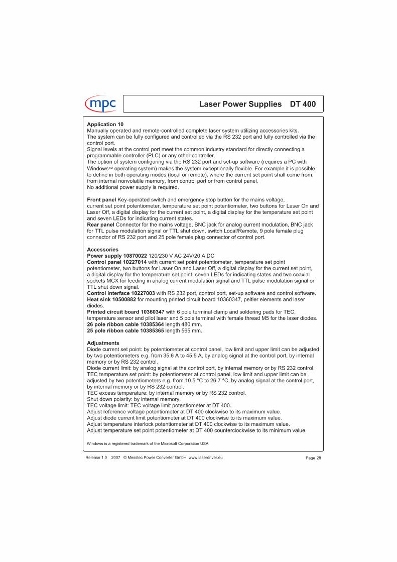
Application 10Manually operated and remote-controlled complete laser system utilizing accessories kits.The system can be fully configured and controlled via the RS 232 port and fully controlled via thecontrol port.Signal levels at the control port meet the common industry standard for directly connecting aprogrammable controller (PLC) or any other controller.The option of system configuring via the RS 232 port and set-up software (requires a PC with
Windows� operating system) makes the system exceptionally flexible. For example it is possibleto define in both operating modes (local or remote), where the current set point shall come from,from internal nonvolatile memory, from control port or from control panel.No additional power supply is required.
Front panel Key-operated switch and emergency stop button for the mains voltage,current set point potentiometer, temperature set point potentiometer, two buttons for Laser On andLaser Off, a digital display for the current set point, a digital display for the temperature set pointand seven LEDs for indicating current states.Rear panel Connector for the mains voltage, BNC jack for analog current modulation, BNC jackfor TTL pulse modulation signal or TTL shut down, switch Local/Remote, 9 pole female plugconnector of RS 232 port and 25 pole female plug connector of control port.
AccessoriesPower supply 10870022 120/230 V AC 24V/20 A DCControl panel 10227014 with current set point potentiometer, temperature set pointpotentiometer, two buttons for Laser On and Laser Off, a digital display for the current set point,a digital display for the temperature set point, seven LEDs for indicating states and two coaxialsockets MCX for feeding in analog current modulation signal and TTL pulse modulation signal orTTL shut down signal.Control interface 10227003 with RS 232 port, control port, set-up software and control software.Heat sink 10500882 for mounting printed circuit board 10360347, peltier elements and laserdiodes.Printed circuit board 10360347 with 6 pole terminal clamp and soldering pads for TEC,temperature sensor and pilot laser and 5 pole terminal with female thread M5 for the laser diodes.26 pole ribbon cable 10385364 length 480 mm.25 pole ribbon cable 10385365 length 565 mm.
AdjustmentsDiode current set point: by potentiometer at control panel, low limit and upper limit can be adjustedby two potentiometers e.g. from 35.6 A to 45.5 A, by analog signal at the control port, by internalmemory or by RS 232 control.Diode current limit: by analog signal at the control port, by internal memory or by RS 232 control.TEC temperature set point: by potentiometer at control panel, low limit and upper limit can beadjusted by two potentiometers e.g. from 10.5 °C to 26.7 °C, by analog signal at the control port,by internal memory or by RS 232 control.TEC excess temperature: by internal memory or by RS 232 control.Shut down polarity: by internal memory.TEC voltage limit: TEC voltage limit potentiometer at DT 400.Adjust reference voltage potentiometer at DT 400 clockwise to its maximum value.Adjust diode current limit potentiometer at DT 400 clockwise to its maximum value.Adjust temperature interlock potentiometer at DT 400 clockwise to its maximum value.Adjust temperature set point potentiometer at DT 400 counterclockwise to its minimum value.
Laser Power Supplies DT 400m c
Release 1.0 2007 © Messtec Power Converter GmbH www.laserdriver.eu Page 28
Windows is a registered trademark of the Microsoft Corporation USA
Application 10
Jumper settingsOperating mode: On/OffShut Down: Active High
Release 1.0 2007 © Messtec Power Converter GmbH www.laserdriver.eu
Laser Power Supplies DT 400m c
Page 29
Laser On
Shut Down
Temperature Interlock
Temperature High
Temperature Low
System Ready
Remote
Switch Locel/Remote
LED Remote
GND
-SV Control Interface
Switch Locel/Remote
+SV Control Interface
25
1
26
1
126
26 pole
25
po
le
13
1
+2
4V
+2
4V
+2
4V
+2
4V
-24
V
-24
V
-24
V
-24
V
PENL
Emergency Stop
Key Switch
PT 1000
Low
On/Off
Temperature Sensor KTY 11-5
Shut Down Active High
Temperature Set Point
Operating Mode Auto On
Reference Voltage
Diode Current Limit
TEC Voltage Limit
Temperature Interlock
+S
VD
iode
Un
it
-SV
Dio
de
Un
it
-SV
TE
CU
nit
+S
VT
EC
Un
it
-TE
C
+T
EC
Te
mp
era
ture
Se
nso
r
Te
mp
era
ture
Se
nso
r
Laser Diode +
Laser Diode -
Switch
Te
mp
era
ture
Se
nso
r
Te
mp
era
ture
Se
nso
r
+T
EC
-TE
C
-Pi lo
tL
ase
r
+P
ilot
La
se
r
X3X4 X2
26
po
le
26
po
le
X4 X3
Current Set Point
Low Limit
Upper Limit
Temperature Set Point
Low Limit
Upper Limit
Current
Temperature
Off On
Local/Remote
Control Interface
10228003
-TE
C
+T
EC
Te
mp
era
ture
Se
nso
r
Te
mp
era
ture
Se
nso
r
-Pi lo
tL
ase
r
+P
ilot
La
se
r
+L
ase
rD
iod
e
-Laser
Dio
de
+L
ase
rD
iod
e
10500882
Heat Sink
10360347
Printed Circuit Board
DT 400
Power Supply 24V
Front Panel
Rear Panel
Control Panel
10227014
Power Entry Module
RS 232 Port Control Port
Fan for heat sink
10500882
X3
26 pole ribbon cable
10385364
10385365
25 pole ribbon cable
BNC jack
Pulse Modulation
Shut Down
BNC jack
Current Modulation

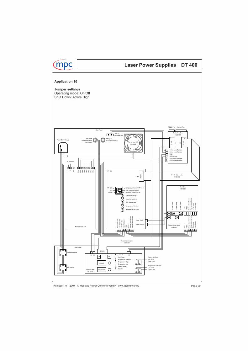
Application 11Manually operated complete laser system with safety interlock utilizing accessories kits.No additional power supply is required.See chapter interlock unit 10228002 for further informations regarding to the functionality of theinterlock unit.
Front panel Key-operated switch and emergency stop button for the mains voltage,a current set point potentiometer, three buttons for Interlock Validation, Laser On and Laser Off,a digital display for the current set point and seven LEDs for indicating states.Rear panel Connector for the mains voltage, BNC jack for analog current modulation, BNC jackfor TTL pulse modulation signal or TTL shut down and a switch for a pilot laser.
AccessoriesPower supply 10870022 120/230 V AC 24V/20 A DC
Control panel 10227015 with current set point potentiometer, three buttons forInterlock Validation, Laser On and Laser Off, a digital display for the current set point, seven LEDsfor indicating states and two coaxial sockets MCX for feeding in analog current modulation signaland TTL pulse modulation signal or TTL shut down signal.The validation button can be disabled by a jumper, this simplifies operating because the buttonmust not be pressed every time an interlock occures. Check country-specific regulations beforedisabling the validation button.
Interlock unit 10228002 with a 5 V output for a pilot laser and a 12 V output for a fan or suchlike.The output voltage for the shutter is selectable by a jumper, either 12 V or the voltage of themains power supply, in this application 24 V.See chapter interlock unit 10228002 for further informations.
Heat sink 10500882 for mounting printed circuit board 10360347, peltier elements and laserdiodes.
Printed circuit board 10360347 with 6 pole terminal clamp and soldering pads for TEC,temperature sensor and pilot laser and5 pole terminal with female thread M5 for the laser diodes.
25 pole ribbon cable 10385363 length 150 mm.26 pole ribbon cable 10385364 length 480 mm.Mounting kit 10228007 including two connection bolts and four lines for connecting the output ofthe DT 400 to the interlock unit.Mounting kit 10228008 including two connecting plates for connecting the output of the interlockunit to the printed circuit board 10360347 at heatsink 10500882.Only required if heatsink 10500882 with printed circuit board is used.
AdjustmentsDiode current set point: potentiometer at control panel, low limit and upper limit can be adjusted bytwo potentiometers e.g. from 35.6 A to 45.5 A.Adjust reference voltage potentiometer at DT 400 clockwise to its maximum value.Diode current limit: diode current limit potentiometer at DT 400.TEC temperature set point: temperature set point potentiometer at DT 400.TEC excess temperature: temperature interlock potentiometer at DT 400.TEC voltage limit: TEC voltage limit potentiometer at DT 400.
Laser Power Supplies DT 400m c
Release 1.0 2007 © Messtec Power Converter GmbH www.laserdriver.eu Page 30
Application 11Jumper settingsOperating mode: On/OffShut Down: Active High
Release 1.0 2007 © Messtec Power Converter GmbH www.laserdriver.eu
Laser Power Supplies DT 400m c
Page 31
Laser On
Shut Down
Temperature Interlock
Temperature High
Temperature Low
System Ready
Safety Interlock
+Interlock
-Interlock
+Shutter
-Shutter
+SV Control Interface
-SV Control Interface
+SV Fan
-SV Fan
+12V Fan
-12V Fan
+5V Pilot Laser
-5V Pilot Laser
1
26
26
po
le
1
25
26
po
le
+SV TEC Unit
-SV TEC Unit
-SV Diode Unit
+SV Diode Unit
126
26 pole
25
po
le
13
1
+2
4V
+2
4V
+2
4V
+2
4V
-24
V
-24
V
-24
V
-24
V
PENL
Emergency Stop
Key Switch
PT 1000
Low
On/Off
Temperature Sensor KTY 11-5
Shut Down Active High
Temperature Set Point
Operating Mode Auto On
Reference Voltage
Diode Current Limit
TEC Voltage Limit
Temperature Interlock
+S
VD
iode
Un
it
-SV
Dio
de
Un
it
-SV
TE
CU
nit
+S
VT
EC
Un
it
-TE
C
+T
EC
Te
mp
era
ture
Se
nso
r
Te
mp
era
ture
Se
nso
r
Laser Diode +
Laser Diode -
X12Laser Diode +
Laser Diode -X14
1 3 5 7
X6
Switch
Interlock Shutter
X3X4
X8X7
26 pole
Current Set Point
Low Limit
Upper Limit
Current
Off Val On
Pilot Laser
10228002
Interlock Unit
DT 400
Power Supply 24V
Front Panel
Rear Panel
-+
Control Panel
10227015
Power Entry Module
Printed Circuit Board
10360347
Heat Sink
10500882
+L
ase
rD
iod
e
-Laser
Dio
de
+L
ase
rD
iod
e
+P
ilot
La
se
r
-Pi lo
tL
ase
r
Te
mp
era
ture
Se
nso
r
Te
mp
era
ture
Se
nso
r
+T
EC
-TE
C
+P
ilot
La
se
r
-Pi lo
tL
ase
r
-TE
C
+T
EC
Te
mp
era
ture
Se
nso
r
Te
mp
era
ture
Se
nso
r
X11
La
ser
Dio
de
+
X1
3L
ase
rD
iod
e-
10385364
26 pole ribbon cable
25 pole ribbon cable
10385363
Shut Down
Pulse Modulation
BNC jack
Current Modulation
BNC jack
10500882
Fan for heat sink
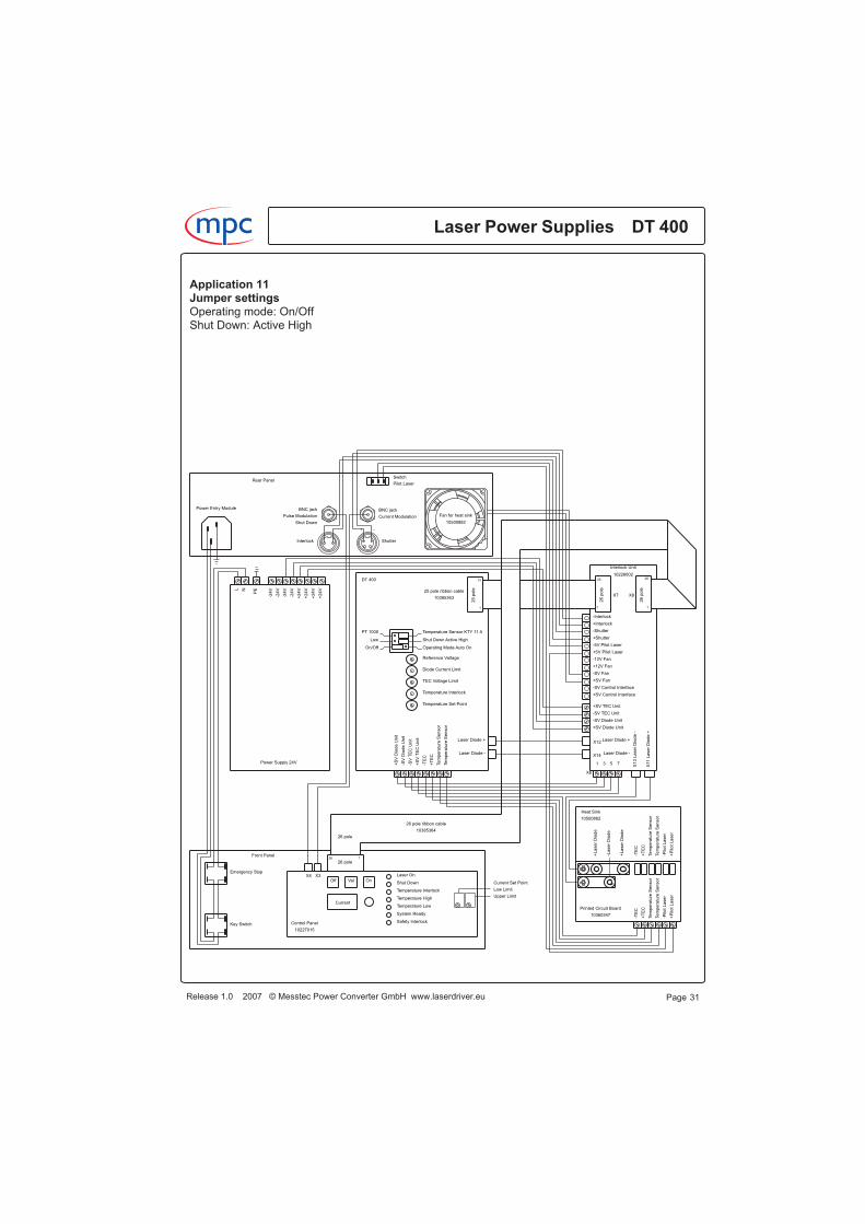
Application 12Manually operated complete laser system with safety interlock utilizing accessories kits.No additional power supply is required.See chapter interlock unit 10228002 for further informations regarding to the functionality of theinterlock unit.
Front panel Key-operated switch and emergency stop button for the mains voltage,a current set point potentiometer, a temperature set point potentiometer, three buttons forInterlock Validation, Laser On and Laser Off, a digital display for the current set point, a digitaldisplay for the temperature set point and seven LEDs for indicating states.Rear panel Connector for the mains voltage, BNC jack for analog current modulation, BNC jackfor TTL pulse modulation signal or TTL shut down, an input for the interlock, an output for a shutterand a switch for a pilot laser.
AccessoriesPower supply 10870022 120/230 V AC 24V/20 A DC
Control panel 10227016 with current set point potentiometer, temperature set pointpotentiometer, three buttons for Interlock Validation, Laser On and Laser Off, a digital display forthe current set point, a digital display for the temperature set point, seven LEDs for indicatingstates and two coaxial sockets MCX for feeding in analog current modulation signal and TTL pulsemodulation signal or TTL shut down signal.The validation button can be disabled by a jumper, this simplifies operating because the buttonmust not be pressed every time an interlock occures. Check country-specific regulations beforedisabling the validation button.
Interlock unit 10228002 with a 5 V output for a pilot laser and a 12 V output for a fan or suchlike.The output voltage for the shutter is selectable by a jumper, either 12 V or the voltage of themains power supply, in this application 24 V.See chapter interlock unit 10228002 for further informations.
Heat sink 10500882 for mounting printed circuit board 10360347, peltier elements and laserdiodes.
Printed circuit board 10360347 with 6 pole terminal clamp and soldering pads for TEC,temperature sensor and pilot laser and 5 pole terminal with female thread M5 for the laser diodes.
25 pole ribbon cable 10385363 length 150 mm.26 pole ribbon cable 10385364 length 480 mm.Mounting kit 10228007 including two connection bolts and four lines for connecting the output ofthe DT 400 to the interlock unit.Mounting kit 10228008 including two connecting plates for connecting the output of the interlockunit to the printed circuit board 10360347 at heatsink 10500882.Only required if heatsink 10500882 with printed circuit board is used.
AdjustmentsDiode current set point: potentiometer at control panel, low limit and upper limit can be adjusted bytwo potentiometers e.g. from 35.6 A to 45.5 A.Adjust reference voltage potentiometer at DT 400 clockwise to its maximum value.Diode current limit: diode current limit potentiometer at DT 400.
Laser Power Supplies DT 400m c
Release 1.0 2007 © Messtec Power Converter GmbH www.laserdriver.eu Page 32

Application 12TEC temperature set point: potentiometer at control panel, low limit and upper limit can beadjusted by two potentiometers e.g. from 10.5 °C to 26.7 °C.Adjust temperature set point potentiometer at DT 400 counterclockwise to its minimum value.TEC excess temperature: temperature interlock potentiometer at DT 400.TEC voltage limit: TEC voltage limit potentiometer at DT 400.
Jumper settingsOperating mode: On/OffShut Down: Active High
Release 1.0 2007 © Messtec Power Converter GmbH www.laserdriver.eu
Laser Power Supplies DT 400m c
Page 33
Laser On
Shut Down
Temperature Interlock
Temperature High
Temperature Low
System Ready
Safety Interlock
+Interlock
-Interlock
+Shutter
-Shutter
+SV Control Interface
-SV Control Interface
+SV Fan
-SV Fan
+12V Fan
-12V Fan
+5V Pilot Laser
-5V Pilot Laser
1
26
26
po
le
1
25
26
po
le
+SV TEC Unit
-SV TEC Unit
-SV Diode Unit
+SV Diode Unit
126
26 pole
25
po
le
13
1
+2
4V
+2
4V
+2
4V
+2
4V
-24
V
-24
V
-24
V
-24
V
PENL
Emergency Stop
Key Switch
PT 1000
Low
On/Off
Temperature Sensor KTY 11-5
Shut Down Active High
Temperature Set Point
Operating Mode Auto On
Reference Voltage
Diode Current Limit
TEC Voltage Limit
Temperature Interlock
+S
VD
iode
Un
it
-SV
Dio
de
Un
it
-SV
TE
CU
nit
+S
VT
EC
Un
it
-TE
C
+T
EC
Te
mp
era
ture
Se
nso
r
Te
mp
era
ture
Se
nso
r
Laser Diode +
Laser Diode -
X12Laser Diode +
Laser Diode -X14
1 3 5 7
X6
Switch
Interlock Shutter
X3X4
X8X7
26 pole
Current Set Point
Low Limit
Upper Limit
Temperature Set Point
Low Limit
Upper Limit
Current
Temperature
Off Val On
Pilot Laser
10228002
Interlock Unit
DT 400
Power Supply 24V
Front Panel
Rear Panel
-+
Control Panel
10227016
Power Entry Module
Printed Circuit Board
10360347
Heat Sink
10500882
+L
ase
rD
iod
e
-Laser
Dio
de
+L
ase
rD
iod
e
+P
ilot
La
se
r
-Pi lo
tL
ase
r
Te
mp
era
ture
Se
nso
r
Te
mp
era
ture
Se
nso
r
+T
EC
-TE
C
+P
ilot
La
se
r
-Pi lo
tL
ase
r
-TE
C
+T
EC
Te
mp
era
ture
Se
nso
r
Te
mp
era
ture
Se
nso
r
X11
La
ser
Dio
de
+
X1
3L
ase
rD
iod
e-
10385364
26 pole ribbon cable
25 pole ribbon cable
10385363
Shut Down
Pulse Modulation
BNC jack
Current Modulation
BNC jack
10500882
Fan for heat sink
Application 13Manually operated and remote-controlled complete laser system with safety interlock utilizingaccessories kits.The system can be fully configured and controlled via the RS 232 port and fully controlled via thecontrol port.Signal levels at the control port meet the common industry standard for directly connecting aprogrammable controller (PLC) or any other controller.The option of system configuring via the RS 232 port and set-up software (requires a PC with
Windows� operating system) makes the system exceptionally flexible. For instance it is possibleto define in both operating modes (local or remote), where the current set point shall come from,from internal nonvolatile memory, from control port or from control panel.No additional power supply is required.See chapter interlock unit 10228002 for further informations regarding to the functionality of theinterlock unit.
Front panel Key-operated switch and emergency stop button for the mains voltage,a current set point potentiometer, three buttons for Interlock Validation, Laser On and Laser Off,a digital display for the current set point and eight LEDs for indicating states.
Rear panel Connector for the mains voltage, BNC jack for analog current modulation, BNC jackfor TTL pulse modulation signal or TTL shut down, a 9 pole female plug connector of RS 232 port,a 25 pole female plug connector of control port, an input for the interlock, an output for a shutter, aswitch for a pilot laser and a switch for Local/Remote.
AccessoriesPower supply 10870022 120/230 V AC 24V/20 A DC
Control panel 10227017 with current set point potentiometer, three buttons forInterlock Validation, Laser On and Laser Off, a digital display for the current set point, eight LEDsfor indicating states and two coaxial sockets MCX for feeding in analog current modulation signaland TTL pulse modulation signal or TTL shut down signal.The validation button can be disabled by a jumper, this simplifies operating because the buttonmust not be pressed every time an interlock occures. Check country-specific regulations beforedisabling the validation button.
Control interface 10227003 with RS 232 port, control port, set-up software and control software.
Interlock unit 10228002 with a 5 V output for a pilot laser, a 12 V output for a fan or suchlike andan output for supplying the control interface.The output voltage for the shutter is selectable by a jumper, either 12 V or the voltage of themains power supply, in this application 24 V.See chapter interlock unit 10228002 for further informations.
Heat sink 10500882 for mounting printed circuit board 10360347, peltier elements and laserdiodes.
Printed circuit board 10360347 with 6 pole terminal clamp and soldering pads for TEC,temperature sensor and pilot laser and 5 pole terminal with female thread M5 for the laser diodes.
Laser Power Supplies DT 400m c
Release 1.0 2007 © Messtec Power Converter GmbH www.laserdriver.eu Page 34
Windows is a registered trademark of the Microsoft Corporation USA

Application 13
5 pole ribbon cable 10385359 length 362 mm.
26 pole ribbon cable 10385360 length 260 mm.
26 pole ribbon cable 10385361 length 525 mm.
Mounting kit 10228007 including two connection bolts and four lines for connecting the output ofthe DT 400 to the interlock unit.
Mounting kit 10228008 including two connecting plates for connecting the output of the interlockunit to the printed circuit board 10360347 at heatsink 10500882.Only required if heatsink 10500882 with printed circuit board is used.
AdjustmentsDiode current set point: by potentiometer at control panel, low limit and upper limit can be adjustedby two potentiometers e.g. from 35.6 A to 45.5 A, by analog signal at the control port, by internalmemory or by RS 232 control.Diode current limit: by analog signal at the control port, by internal memory or by RS 232 control.TEC temperature set point: by analog signal at the control port, by internal memory or byRS 232 control.TEC excess temperature: by internal memory or by RS 232 control.Shut down polarity: by internal memory.TEC voltage limit: TEC voltage limit potentiometer at DT 400.Adjust reference voltage potentiometer at DT 400 clockwise to its maximum value.Adjust diode current limit potentiometer at DT 400 clockwise to its maximum value.Adjust temperature interlock potentiometer at DT 400 clockwise to its maximum value.Adjust temperature set point potentiometer at DT 400 counterclockwise to its minimum value.
Jumper settingsOperating mode: On/OffShut Down: Active High
Release 1.0 2007 © Messtec Power Converter GmbH www.laserdriver.eu
Laser Power Supplies DT 400m c
Page 35
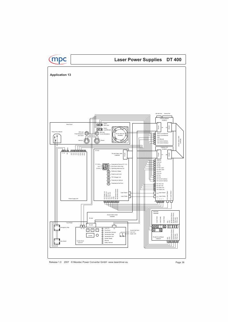
Application 13
Laser Power Supplies DT 400m c
Release 1.0 2007 © Messtec Power Converter GmbH www.laserdriver.eu Page 36
Laser On
Shut Down
Temperature Interlock
Temperature High
Temperature Low
System Ready
Remote
Safety Interlock
Switch Locel/Remote
LED Remote
GND
-SV Control Interface
Switch Locel/Remote
+SV Control Interface
+Interlock
-Interlock
+Shutter
-Shutter
+SV Control Interface
-SV Control Interface
+SV Fan
-SV Fan
+12V Fan
-12V Fan
+5V Pilot Laser
-5V Pilot Laser
26
1
1
26
26
po
le
26
1
1
25
26
po
le
+SV TEC Unit
-SV TEC Unit
-SV Diode Unit
+SV Diode Unit
126
26 pole
25
po
le
13
1
+2
4V
+2
4V
+2
4V
+2
4V
-24
V
-24
V
-24
V
-24
V
PENL
Emergency Stop
Key Switch
PT 1000
Low
On/Off
Temperature Sensor KTY 11-5
Shut Down Active High
Temperature Set Point
Operating Mode Auto On
Reference Voltage
Diode Current Limit
TEC Voltage Limit
Temperature Interlock
+S
VD
iode
Un
it
-SV
Dio
de
Un
it
-SV
TE
CU
nit
+S
VT
EC
Un
it
-TE
C
+T
EC
Te
mp
era
ture
Se
nso
r
Te
mp
era
ture
Se
nso
r
Laser Diode +
Laser Diode -
X12Laser Diode +
Laser Diode -X14
1 3 5 7
X6
Switch
Switch
Interlock Shutter
X3X4 X2
26
po
le
26
po
le
X8X7
X4 X3
26 pole
Current Set Point
Low Limit
Upper Limit
Current
Off Val On
Pilot Laser
Local/Remote
Control Interface
10228003
10228002
Interlock Unit
DT 400
Power Supply 24V
Front Panel
Rear Panel
-+
Control Panel
10227017
Power Entry Module
RS 232 Port Control Port
Printed Circuit Board
10360347
Heat Sink
10500882
+L
ase
rD
iod
e
-Laser
Dio
de
+L
ase
rD
iod
e
+P
ilot
La
se
r
-Pi lo
tL
ase
r
Te
mp
era
ture
Se
nso
r
Te
mp
era
ture
Se
nso
r
+T
EC
-TE
C
+P
ilot
La
se
r
-Pi lo
tL
ase
r
-TE
C
+T
EC
Te
mp
era
ture
Se
nso
r
Te
mp
era
ture
Se
nso
r
X11
La
ser
Dio
de
+
X1
3L
ase
rD
iod
e-
10385361
26 pole ribbon cable
26
po
leri
bbo
nca
ble
10
3853
60
25 pole ribbon cable
10385359
Shut Down
Pulse Modulation
BNC jack
Current Modulation
BNC jack
10500882
Fan for heat sink
Application 14Manually operated and remote-controlled complete laser system with safety interlock utilizingaccessories kits.The system can be fully configured and controlled via the RS 232 port and fully controlled via thecontrol port.Signal levels at the control port meet the common industry standard for directly connecting aprogrammable controller (PLC) or any other controller.The option of system configuring via the RS 232 port and set-up software (requires a PC with
Windows� operating system) makes the system exceptionally flexible. For instance it is possibleto define in both operating modes (local or remote), where the current set point shall come from,from internal nonvolatile memory, from control port or from control panel.No additional power supply is required.See chapter interlock unit 10228002 for further informations regarding to the functionality of theinterlock unit.
Front panel Key-operated switch and emergency stop button for the mains voltage,a current set point potentiometer, a temperature set point potentiometer, three buttons forInterlock Validation, Laser On and Laser Off, a digital display for the current set point, a digitaldisplay for the temperature set point and eight LEDs for indicating states.
Rear panel Connector for the mains voltage, BNC jack for analog current modulation, BNC jackfor TTL pulse modulation signal or TTL shut down, a 9 pole female plug connector of RS 232 port,a 25 pole female plug connector of control port, an input for the interlock, an output for a shutter, aswitch for a pilot laser and a switch for Local/Remote.
AccessoriesPower supply 10870022 120/230 V AC 24V/20 A DC
Control panel 10227018 with current set point potentiometer, temperature set pointpotentiometer, three buttons for Interlock Validation, Laser On and Laser Off, a digital display forthe current set point, digital display for the temperature set point, eight LEDs for indicating statesand two coaxial sockets MCX for feeding in analog current modulation signal and TTL pulsemodulation signal or TTL shut down signal.The validation button can be disabled by a jumper, this simplifies operating because the buttonmust not be pressed every time an interlock occures. Check country-specific regulations beforedisabling the validation button.
Control interface 10227003 with RS 232 port, control port, set-up software and control software.
Interlock unit 10228002 with a 5 V output for a pilot laser, a 12 V output for a fan or suchlike andan output for supplying the control interface.The output voltage for the shutter is selectable by a jumper, either 12 V or the voltage of themains power supply, in this application 24 V.See chapter interlock unit 10228002 for further informations.
Heat sink 10500882 for mounting printed circuit board 10360347, peltier elements and laserdiodes.
Printed circuit board 10360347 with 6 pole terminal clamp and soldering pads for TEC,temperature sensor and pilot laser and 5 pole terminal with female thread M5 for the laser diodes.
Release 1.0 2007 © Messtec Power Converter GmbH www.laserdriver.eu
Laser Power Supplies DT 400m c
Page 37
Windows is a registered trademark of the Microsoft Corporation USA
Application 14
5 pole ribbon cable 10385359 length 362 mm.
26 pole ribbon cable 10385360 length 260 mm.
26 pole ribbon cable 10385361 length 525 mm.
Mounting kit 10228007 including two connection bolts and four lines for connecting the output ofthe DT 400 to the interlock unit.
Mounting kit 10228008 including two connecting plates for connecting the output of the interlockunit to the printed circuit board 10360347 at heatsink 10500882.Only required if heatsink 10500882 with printed circuit board is used.
Adjustments
Diode current set point: by potentiometer at control panel, low limit and upper limit can be adjustedby two potentiometers e.g. from 35.6 A to 45.5 A, by analog signal at the control port, by internalmemory or by RS 232 control.Diode current limit: by analog signal at the control port, by internal memory or by RS 232 control.TEC temperature set point: by potentiometer at control panel, low limit and upper limit can beadjusted by two potentiometers e.g. from 10.5 °C to 26.7 °C, by analog signal at the control port,by internal memory or by RS 232 control.TEC excess temperature: by internal memory or by RS 232 control.Shut down polarity: by internal memory.TEC voltage limit: TEC voltage limit potentiometer at DT 400.Adjust reference voltage potentiometer at DT 400 clockwise to its maximum value.Adjust diode current limit potentiometer at DT 400 clockwise to its maximum value.Adjust temperature interlock potentiometer at DT 400 clockwise to its maximum value.Adjust temperature set point potentiometer at DT 400 counterclockwise to its minimum value.
Jumper settingsOperating mode: On/OffShut Down: Active High
Laser Power Supplies DT 400m c
Release 1.0 2007 © Messtec Power Converter GmbH www.laserdriver.eu Page 38

Application 14
Release 1.0 2007 © Messtec Power Converter GmbH www.laserdriver.eu
Laser Power Supplies DT 400m c
Page 39
Laser On
Shut Down
Temperature Interlock
Temperature High
Temperature Low
System Ready
Remote
Safety Interlock
Switch Locel/Remote
LED Remote
GND
-SV Control Interface
Switch Locel/Remote
+SV Control Interface
+Interlock
-Interlock
+Shutter
-Shutter
+SV Control Interface
-SV Control Interface
+SV Fan
-SV Fan
+12V Fan
-12V Fan
+5V Pilot Laser
-5V Pilot Laser
26
1
1
26
26
po
le
26
1
1
25
26
po
le
+SV TEC Unit
-SV TEC Unit
-SV Diode Unit
+SV Diode Unit
126
26 pole
25
po
le
13
1
+2
4V
+2
4V
+2
4V
+2
4V
-24
V
-24
V
-24
V
-24
V
PENL
Emergency Stop
Key Switch
PT 1000
Low
On/Off
Temperature Sensor KTY 11-5
Shut Down Active High
Temperature Set Point
Operating Mode Auto On
Reference Voltage
Diode Current Limit
TEC Voltage Limit
Temperature Interlock
+S
VD
iode
Un
it
-SV
Dio
de
Un
it
-SV
TE
CU
nit
+S
VT
EC
Un
it
-TE
C
+T
EC
Te
mp
era
ture
Se
nso
r
Te
mp
era
ture
Se
nso
r
Laser Diode +
Laser Diode -
X12Laser Diode +
Laser Diode -X14
1 3 5 7
X6
Switch
Switch
Interlock Shutter
X3X4 X2
26
po
le
26
po
le
X8X7
X4 X3
26 pole
Current Set Point
Low Limit
Upper Limit
Temperature Set Point
Low Limit
Upper Limit
Current
Temperature
Off Val On
Pilot Laser
Local/Remote
Control Interface
10228003
10228002
Interlock Unit
DT 400
Power Supply 24V
Front Panel
Rear Panel
-+
Control Panel
10227018
Power Entry Module
RS 232 Port Control Port
Printed Circuit Board
10360347
Heat Sink
10500882
+L
ase
rD
iod
e
-Laser
Dio
de
+L
ase
rD
iod
e
+P
ilot
La
se
r
-Pi lo
tL
ase
r
Te
mp
era
ture
Se
nso
r
Te
mp
era
ture
Se
nso
r
+T
EC
-TE
C
+P
ilot
La
se
r
-Pi lo
tL
ase
r
-TE
C
+T
EC
Te
mp
era
ture
Se
nso
r
Te
mp
era
ture
Se
nso
r
X11
La
ser
Dio
de
+
X1
3L
ase
rD
iod
e-
10385361
26 pole ribbon cable
26
po
leri
bbo
nca
ble
10
3853
60
25 pole ribbon cable
10385359
Shut Down
Pulse Modulation
BNC jack
Current Modulation
BNC jack
10500882
Fan for heat sink

Terminals
Laser Power Supplies DT 400m c
Release 1.0 2007 © Messtec Power Converter GmbH www.laserdriver.eu Page 40
Temperature Sensor KTY 11-5
Shut Down Active High
Operating Mode Auto On
Reference Voltage
PT 1000
Low
On/Off
Diode Current Limit
TEC Voltage Limit
Temperature Interlock
Temperature Set Point
141
Su
pp
lyV
olta
ge
Dio
de
Unit
Su
pp
lyV
olta
ge
Dio
de
Unit
Su
pply
Vo
ltag
eT
EC
Unit
Su
pply
Vo
ltag
eT
EC
Unit
Th
erm
oe
lectric
alC
oo
ler
Th
erm
oe
lectric
alC
oo
ler
Te
mpe
ratu
reS
en
so
r
Te
mpe
ratu
reS
en
so
r
Lase
rD
iod
e
Lase
rD
iod
e
+--++- -+
CA
UT
ION
Do
no
tre
mo
ve
cove
rN
ou
se
rse
rvic
ea
ble
co
mp
on
en
tsin
sid
eR
efe
rserv
icin
gto
qua
lified
pe
rso
nn
el
Me
sste
cP
ow
er
Co
nve
rter
Gm
bH
Gru
be
41
D-
82
37
7P
en
zbe
rgw
ww
.lase
rpow
ers
up
ply.e
u
Re
fere
nce
Vo
ltag
e
Dio
de
Cu
rren
tL
imit
TE
CV
olta
ge
Lim
it
Tem
pera
ture
Inte
rlock
Tem
pera
ture
Se
tP
oin
t
Te
mp
era
ture
Se
nso
rP
T1
00
0
Shu
tD
ow
nA
ctiv
eH
igh
Shu
tD
ow
nA
ctiv
eL
ow
Te
mp
era
ture
Se
nso
rK
TY
11-5
Op
era
ting
Mo
de
On/O
ff
Op
era
ting
Mo
de
Au
toO
n
Te
mp
era
ture
Se
nso
r
Te
mp
era
ture
Se
nso
r
Th
erm
oe
lectric
alC
oole
r
Th
erm
oe
lectric
alC
oole
r
Sup
ply
Vo
ltage
TE
CU
nit
Sup
ply
Vo
ltage
TE
CU
nit
Sup
ply
Vo
ltage
Dio
de
Unit
Sup
ply
Vo
ltage
Dio
de
Unit
La
ser
Dio
de
La
ser
Dio
de
La
se
rP
ow
er
Su
pp
ly
Ge
rma
nP
ate
nt
DE
19
70
01
00
C2
Eu
rop
ea
nP
ate
nt
EP
08
52
42
2B
1M
ad
ein
Ge
rma
ny
Mo
del
Mo
delC
od
e
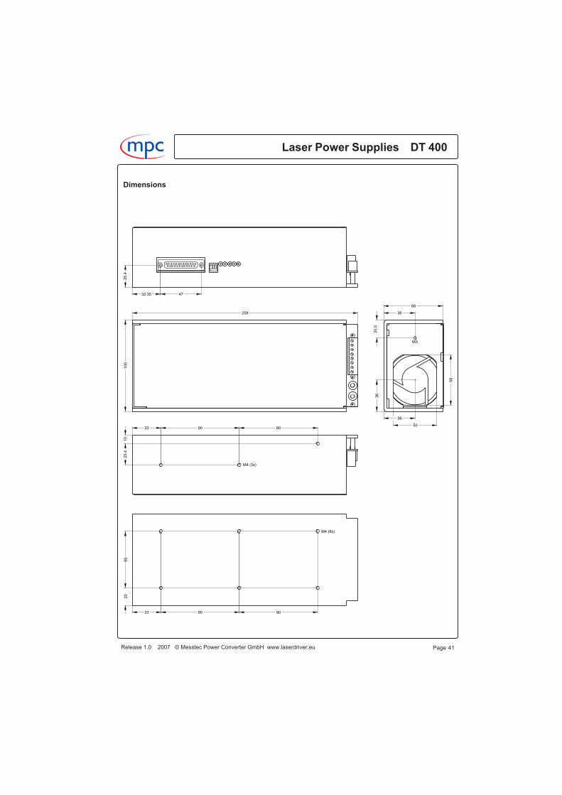
Dimensions
Release 1.0 2007 © Messtec Power Converter GmbH www.laserdriver.eu
Laser Power Supplies DT 400m c
Page 41
M4 (6x)
909033
65
20
36
M3
20.5
58
36
36
50
68
M4 (3x)
909033
25.4
10
105
259
25.4
4732.35
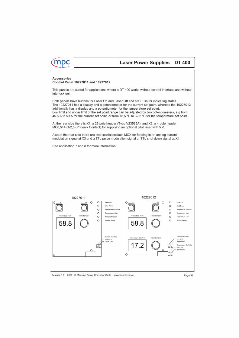
AccessoriesControl Panel 10227011 and 10227012
This panels are suited for applications where a DT 400 works without control interface and withoutinterlock unit.
Both panels have buttons for Laser On and Laser Off and six LEDs for indicating states.The 10227011 has a display and a potentiometer for the current set point, whereas the 10227012additionally has a display and a potentiometer for the temperature set point.Low limit and upper limit of the set point range can be adjusted by two potentiometers, e.g from45.5 A to 59 A for the current set point, or from 18,5 °C to 32,2 °C for the temperature set point.
At the rear side there is X1, a 26 pole header (Tyco V23535A), and X2, a 4 pole headerMC0,5/ 4-G-2,5 (Phoenix Contact) for supplying an optional pilot laser with 5 V.
Also at the rear side there are two coaxial sockets MCX for feeding in an analog currentmodulation signal at X3 and a TTL pulse modulation signal or TTL shut down signal at X4.
See application 7 and 8 for more information.
Laser Power Supplies DT 400m c
Release 1.0 2007 © Messtec Power Converter GmbH www.laserdriver.eu Page 42
58.8
Upper Limit
Low Limit
Current Set Point
Laser On Laser Off
Current Set Point Potentiometer
Laser On
Shut Down
Temperature Interlock
Temperature High
Temperature Low
System Ready
17.2
58.8
Temperature Set Point
Low Limit
Upper Limit
Upper Limit
Low Limit
Current Set Point
Laser On Laser Off
Current Set Point
Temperature Set Point Potentiometer
Potentiometer
Laser On
Shut Down
Temperature Interlock
Temperature High
Temperature Low
System Ready
1022701210227011
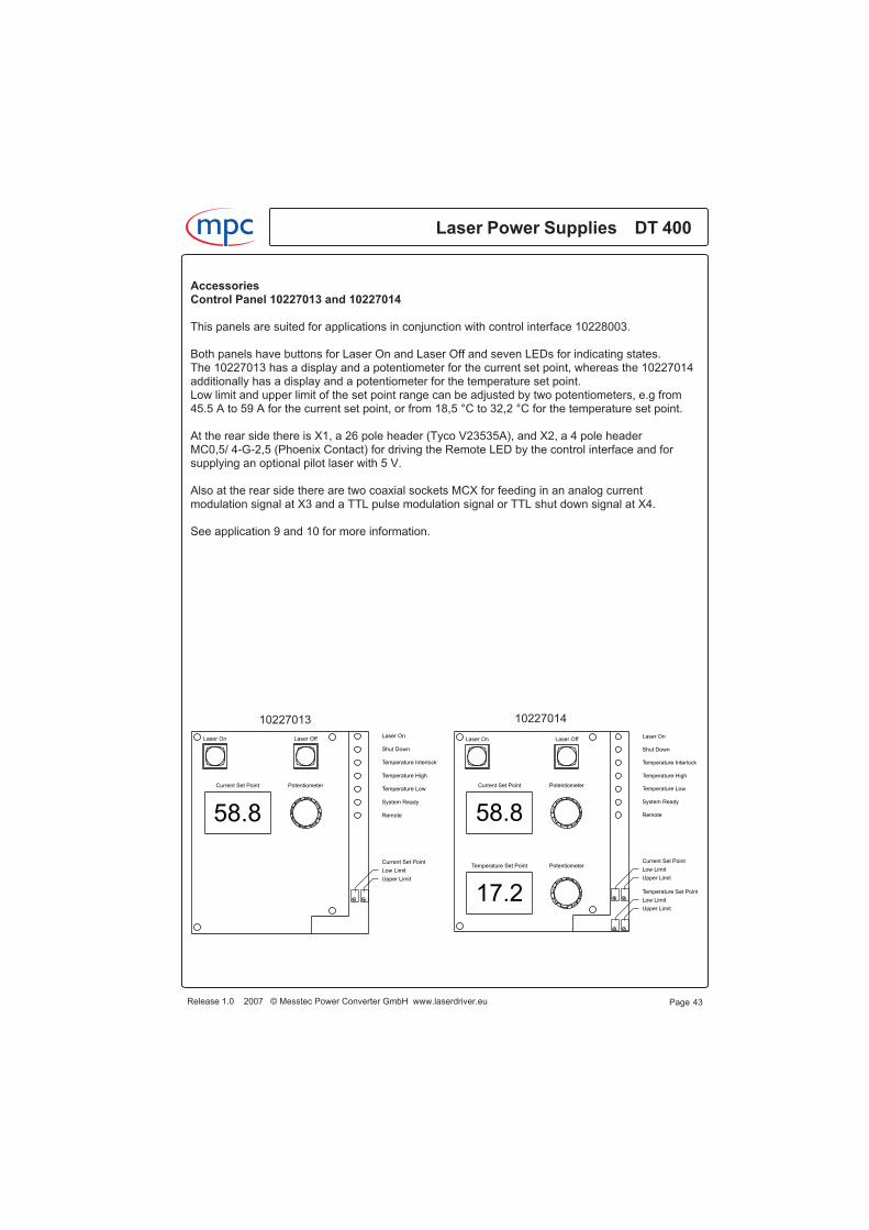
AccessoriesControl Panel 10227013 and 10227014
This panels are suited for applications in conjunction with control interface 10228003.
Both panels have buttons for Laser On and Laser Off and seven LEDs for indicating states.The 10227013 has a display and a potentiometer for the current set point, whereas the 10227014additionally has a display and a potentiometer for the temperature set point.Low limit and upper limit of the set point range can be adjusted by two potentiometers, e.g from45.5 A to 59 A for the current set point, or from 18,5 °C to 32,2 °C for the temperature set point.
At the rear side there is X1, a 26 pole header (Tyco V23535A), and X2, a 4 pole headerMC0,5/ 4-G-2,5 (Phoenix Contact) for driving the Remote LED by the control interface and forsupplying an optional pilot laser with 5 V.
Also at the rear side there are two coaxial sockets MCX for feeding in an analog currentmodulation signal at X3 and a TTL pulse modulation signal or TTL shut down signal at X4.
See application 9 and 10 for more information.
Release 1.0 2007 © Messtec Power Converter GmbH www.laserdriver.eu
Laser Power Supplies DT 400m c
Page 43
58.8
Upper Limit
Low Limit
Current Set Point
Laser On Laser Off
Current Set Point Potentiometer
Laser On
Shut Down
Temperature Interlock
Temperature High
Temperature Low
System Ready
Remote
17.2
58.8
Temperature Set Point
Low Limit
Upper Limit
Upper Limit
Low Limit
Current Set Point
Laser On Laser Off
Current Set Point
Temperature Set Point Potentiometer
Potentiometer
Laser On
Shut Down
Temperature Interlock
Temperature High
Temperature Low
System Ready
Remote
1022701410227013
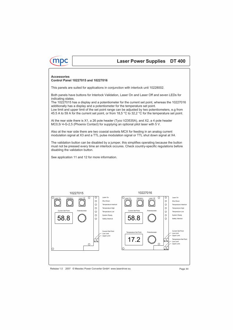
AccessoriesControl Panel 10227015 and 10227016
This panels are suited for applications in conjunction with interlock unit 10228002.
Both panels have buttons for Interlock Validation, Laser On and Laser Off and seven LEDs forindicating states.The 10227015 has a display and a potentiometer for the current set point, whereas the 10227016additionally has a display and a potentiometer for the temperature set point.Low limit and upper limit of the set point range can be adjusted by two potentiometers, e.g from45.5 A to 59 A for the current set point, or from 18,5 °C to 32,2 °C for the temperature set point.
At the rear side there is X1, a 26 pole header (Tyco V23535A), and X2, a 4 pole headerMC0,5/ 4-G-2,5 (Phoenix Contact) for supplying an optional pilot laser with 5 V.
Also at the rear side there are two coaxial sockets MCX for feeding in an analog currentmodulation signal at X3 and a TTL pulse modulation signal or TTL shut down signal at X4.
The validation button can be disabled by a jumper, this simplifies operating because the buttonmust not be pressed every time an interlock occures. Check country-specific regulations beforedisabling the validation button.
See application 11 and 12 for more information.
Laser Power Supplies DT 400m c
Release 1.0 2007 © Messtec Power Converter GmbH www.laserdriver.eu Page 44
58.8
Upper Limit
Low Limit
Current Set Point
ValidationLaser On Laser Off
Current Set Point Potentiometer
Laser On
Shut Down
Temperature Interlock
Temperature High
Temperature Low
System Ready
Safety Interlock
17.2
58.8
Temperature Set Point
Low Limit
Upper Limit
Upper Limit
Low Limit
Current Set Point
ValidationLaser On Laser Off
Current Set Point
Temperature Set Point Potentiometer
Potentiometer
Laser On
Shut Down
Temperature Interlock
Temperature High
Temperature Low
System Ready
Safety Interlock
1022701610227015

AccessoriesControl Panel 10227017 and 10227018
This panels are suited for applications in conjunction with interlock unit 10228002 and controlinterface 10228003.Both panels have buttons for Interlock Validation, Laser On and Laser Off and eight LEDs forindicating states.The 10227017 has a display and a potentiometer for the current set point, whereas the 10227018additionally has a display and a potentiometer for the temperature set point.Low limit and upper limit of the set point range can be adjusted by two potentiometers, e.g from45.5 A to 59 A for the current set point, or from 18,5 °C to 32,2 °C for the temperature set point.
At the rear side there is X1, a 26 pole header (Tyco V23535A), and X2, a 4 pole headerMC0,5/ 4-G-2,5 (Phoenix Contact) for driving the Remote LED by the control interface and forsupplying an optional pilot laser with 5 V.
Also at the rear side there are two coaxial sockets MCX for feeding in an analog currentmodulation signal at X3 and a TTL pulse modulation signal or TTL shut down signal at X4.
The validation button can be disabled by a jumper, this simplifies operating because the buttonmust not be pressed every time an interlock occures. Check country-specific regulations beforedisabling the validation button.
See application 13 and 14 for more information.
Release 1.0 2007 © Messtec Power Converter GmbH www.laserdriver.eu
Laser Power Supplies DT 400m c
Page 45
58.8
Upper Limit
Low Limit
Current Set Point
ValidationLaser On Laser Off
Current Set Point Potentiometer
Laser On
Shut Down
Temperature Interlock
Temperature High
Temperature Low
System Ready
Remote
Safety Interlock
17.2
58.8
Temperature Set Point
Low Limit
Upper Limit
Upper Limit
Low Limit
Current Set Point
ValidationLaser On Laser Off
Current Set Point
Temperature Set Point Potentiometer
Potentiometer
Laser On
Shut Down
Temperature Interlock
Temperature High
Temperature Low
System Ready
Remote
Safety Interlock
1022701810227017
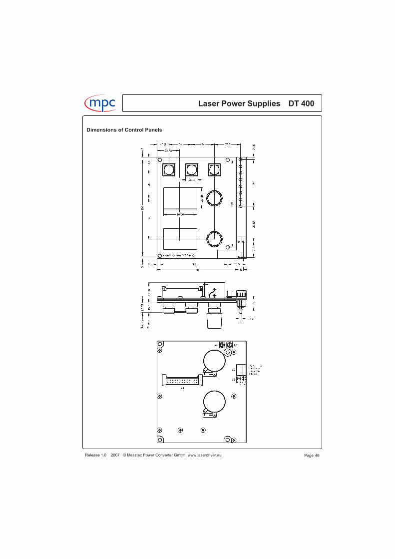
Dimensions of Control Panels
Laser Power Supplies DT 400m c
Release 1.0 2007 © Messtec Power Converter GmbH www.laserdriver.eu Page 46
AccessoriesInterlock Unit 10228002
A safety interlock is required, e.g. if a laser operates in a machine where parts will be inserted orremoved manually. In this case laser radiation has to be interrupted immediately and the systemmust be keep in a safe off-state.A safe off-state may be achieved by a safety beam shutter, but in most cases there is less spacein the optical path.A better and cost saving way is to switch off the laser power supply and keep it in a safe off-state.Safe off-state means, that the laser power supply must be electrically disconnected, switching offby a digital signal like a shut down or a disable signal is forbidden for a safe operating.It is regulation, that disconnection must be happen by a relay or a switch, the use ofsemiconductors or electronic switches for disconnecting is not allowed. The properly function ofthe relay must be supervised in a manner that malfunction does not lead to an unsafe state.
The interlock unit 10228002 complies with regulation and has a lot of additional features forachieving a safe off-state within a very short time.There are two relays, connected in series, a working relay and an emergency relay. Theemergency relay is always closed, the working relay acts if an interlock occures. The normallyopen contact and the normally closed contact of both relays are supervised.If the working relays does not work properly or if there is a failure in the interlock unit, theemergency relays will be de-energized and turns the system in a steady off-state.Every time the mains voltage is turned on, the function of the emergency relays is checked toensure correct operation. If there is a failure, the system cannot be turned on.Both relays are working currentless for achieving maximum life time.
If an interlock occures, the output for the laser diodes will be short circuited immediately by asemiconductor to ensure that laser radiation will be stopped within a few microseconds.Simultaneously the DT 400 will be turned off and the working relay will be de-energized. At thesame time the input capacitors of the DT 400 will be discharged to ensure that no stored energywill cause laser radiation if there is any malfunction.Also the semiconductor and the circuit for discharging are supervised.Additionally the interlock unit has an output for a beam shutter. The output is also supervised.
The interlock unit is a open frame component, which is generally mounted beside a verticallymounted DT 400.The DT 400 to interlock unit connection will be done by mounting kit 10228007, including twoconnection bolts for mounting at X12 and X14 and four 2,5 qmm wires for connecting atterminal X6.Laser diodes are connected at X11 and X13. If heatsink 10500882 with printed circuit board10360347 is used, mounting kit 10228008 including two connecting plates is required.The data connection to the DT 400 will be done by a 25 pole ribbon cable 10385363 at X7.A control panel can be connected at X8 via a 26 pole ribbon cable 10385364.See application 11 and 12 for further information.
If the interlock unit is used in conjunction with control interface 10228003, then this can befastened directly at the interlock unit's metal plate. In this case take cable 10385359 instead of10385363 and take cable 10385361instead of 10385364, this makes wiring easier.For connecting the control interface to the interlock unit, a 26 pole ribbon cable 10385360 isrequired.See application 13 and 14 for further information.
Release 1.0 2007 © Messtec Power Converter GmbH www.laserdriver.eu
Laser Power Supplies DT 400m c
Page 47
AccessoriesInterlock Unit 10228002
Terminals X1 X2 X3 X4Connection bolts with female thread M3 for connecting the supply voltage for the diode unit andthe TEC unit of the DT 400.Use ring terminals and wires with a cross section of 2,5 qmm.
Termination block X5Spring-cage 12 pole termination block.Conductor cross section stranded minimum: 0.2 qmm, maximum: 1.5 qmm.
Signal descriptionInterlock pin 21, 23Input for a positive opening contact. A interlock occures if pin 21 and pin 23 are notinterconnected.Interlock voltage (contact open): 12 V.Interlock current (contact closed): approx. 1 mA.For unlocking, a +5 V validation signal of at least a few milliseconds at pin 21 of X8 is required.Generally this will be done by the validation button of the control panels.
SV Control Interface pin 1, 3Supply voltage for a control interface or suchlike. The voltage is the same like the SV TEC unit.For instance if you have a 24 V power supply, the SV Control Interface voltage will also be 24 V.
SV Fan pin 5, 7Supply voltage for a fan or suchlike. The voltage is the same like the SV TEC unit. For instance ifyou have a 24 V power supply for supplying the TEC unit, the SV Fan voltage will also be 24 V.
Laser Power Supplies DT 400m c
Release 1.0 2007 © Messtec Power Converter GmbH www.laserdriver.eu Page 48
Inputs
Pin Name Function
2123
+Interlock-Interlock
Interlock inputInterlock input
Outputs
Pin Name Function
135791113151719
+SV Control Interface-SV Control Interface+SV Fan-SV Fan+12V Fan-12V Fan+5V Pilot Laser-5V Pilot Laser-Shutter+Shutter
+Supply voltage for a control interface-Supply voltage fo a control interface+Supply voltage for a fan-Supply voltage for a fan+12V Supply Voltage for a fan-12V Supply voltage for a fan+5V Supply voltage for a pilot laser-5V Supply voltage for a pilot laser- Supply voltage for a shutter+Supply voltage for a shutter
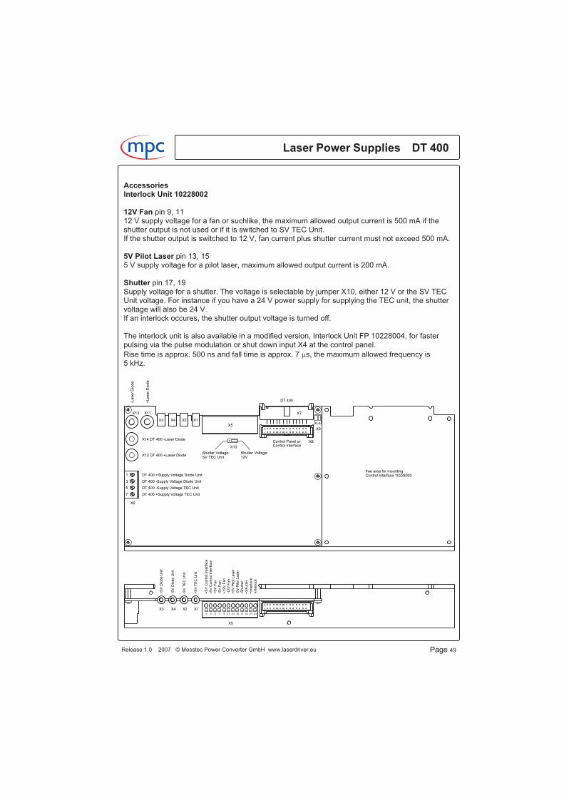
AccessoriesInterlock Unit 10228002
12V Fan pin 9, 1112 V supply voltage for a fan or suchlike, the maximum allowed output current is 500 mA if theshutter output is not used or if it is switched to SV TEC Unit.If the shutter output is switched to 12 V, fan current plus shutter current must not exceed 500 mA.
5V Pilot Laser pin 13, 155 V supply voltage for a pilot laser, maximum allowed output current is 200 mA.
Shutter pin 17, 19Supply voltage for a shutter. The voltage is selectable by jumper X10, either 12 V or the SV TECUnit voltage. For instance if you have a 24 V power supply for supplying the TEC unit, the shuttervoltage will also be 24 V.If an interlock occures, the shutter output voltage is turned off.
The interlock unit is also available in a modified version, Interlock Unit FP 10228004, for fasterpulsing via the pulse modulation or shut down input X4 at the control panel.
Rise time is approx. 500 ns and fall time is approx. 7 �s, the maximum allowed frequency is5 kHz.
Release 1.0 2007 © Messtec Power Converter GmbH www.laserdriver.eu
Laser Power Supplies DT 400m c
Page 49
2
1
1 3 5 7 9 11 13 15 17 19 21 23
2
1
X9
X8
X7
X10
X6
X5
X1X2X4X3
X11X13
X3 X4 X2 X1
DT 400 +Supply Voltage Diode Unit
DT 400 -Supply Voltage Diode Unit
DT 400 -Supply Voltage TEC Unit
DT 400 +Supply Voltage TEC Unit
1
3
5
7
DT 400 +Laser Diode
DT 400 -Laser Diode
+L
ase
rD
iod
e
-Lase
rD
iod
e
X5
DT 400
Control Panel orControl Interface
Shutter Voltage:12V
Shutter Voltage:SV TEC Unit
X14
X12
+S
VC
on
trolIn
terf
ace
-SV
Contr
olIn
terf
ace
+S
VF
an
-SV
Fa
n
+12
VF
an
-12V
Fa
n
+5V
Pilo
tL
aser
-5V
Pilo
tLase
r
-Shutt
er
+S
hutt
er
+In
terlock
-Inte
rlo
ck
+S
VD
iode
Unit
-SV
Dio
de
Unit
-SV
TE
CU
nit
+S
VT
EC
Un
it
free area for mountingControl Interface 10228003

AccessoriesInterlock Unit 10228002Dimensions
Laser Power Supplies DT 400m c
Release 1.0 2007 © Messtec Power Converter GmbH www.laserdriver.eu Page 50
21 108.5 108.5 21
2
1
1 3 5 7 9 11 13 15 17 19 21 23
2
1X3 X4 X2 X1
X9
X8
X7
X10
X6
X5
X1X2X4X3
X11X13
DT 400 +Supply Voltage Diode Unit
DT 400 -Supply Voltage Diode Unit
DT 400 -Supply Voltage TEC Unit
DT 400 +Supply Voltage TEC Unit
1
3
5
7
DT 400 +Laser Diode
DT 400 -Laser Diode
DT 400
Control Panel orControl Interface
Shutter Voltage:12V
Shutter Voltage:SV TEC Unit
X14
X12
fastening screw thread M3 (3x)
6.5
23
.534
11
3.5
11
5.4
259
AccessoriesControl Interface 10228003
The control interface 10228003 is a microprocessor controlled interface with a control port and aRS 232 port.Signal levels at the control port meet the common industry standard such as analog levels of0 ... 10 V for inputs and outputs and digital levels up to 30 V for directly connecting a programma-ble controller (PLC) or any other controller.
The system can be fully controlled via the control port and fully configured and controlled via theRS 232 port.The option of system configuring via the RS 232 port and set-up software (requires a PC with
Windows� operating system) makes the system exceptionally flexible.It is possible to define in both operating modes (local or remote), where the current set point andthe temperature set point shall come from, from internal nonvolatile memory, from control port orfrom a control panel and it is possible to define where the current limit shall come from, frominternal nonvolatile memory ore from control port.
Example 1You can configure a remote controlled system in such a way that it is controlled by a PLC at thecontrol port, but nevertheless the current set point can be adjusted manually at the control panel.The current limit value and the temperature set point is given via the control port or by the internalnonvolatile memory.This allows remote operating with the possibility of manually correcting manufacturing results.
Example 2You can configure a local controlled system in such a way that it is manually controlled by thebuttons at the control panel, but the current set point or the temperature set point cannot be adjus-ted manually. This values are given by the internal nonvolatile memory.
The control interface 10228003 is a single printed circuit board with five mounting holes.It can be mounted anywhere.The mounting holes must be connected to protected earth (PE) for electromagnetic interferencereasons.
There is also a mounting kit 10228005 available. In this case the printed circuit board is mountedon a metal plate, it's the same like the interlock unit's plate.The advantage is that if you have a case with a rear panel which has an opening for the controlport and the RS 232 port, the kit can be mounted vertically beside the DT 400 in such a way thatthe port connectors can be used directly without additional connectors and cables.
The data connection to the DT 400 is be done by a 25 pole ribbon cable 10385365 at X3.A control panel can be connected at X4 via a 26 pole ribbon cable 10385364.See application 9 and 10 for further information.
If the control interface is used in conjunction with the interlock unit 10228002, it can be fastened atthe metal plate of the interlock unit. Use mounting kit 10228006, containing 5 distance bolts and10 screws.
Release 1.0 2007 © Messtec Power Converter GmbH www.laserdriver.eu
Laser Power Supplies DT 400m c
Page 51
Windows is a registered trademark of the Microsoft Corporation USA
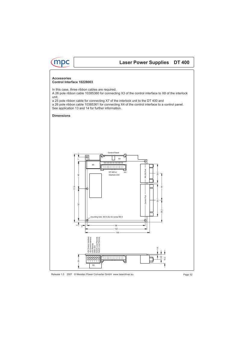
AccessoriesControl Interface 10228003
In this case, three ribbon cables are required.A 26 pole ribbon cable 10385360 for connecting X3 of the control interface to X8 of the interlockunit,a 25 pole ribbon cable for connecting X7 of the interlock unit to the DT 400 anda 26 pole ribbon cable 10385361 for connecting X4 of the control interface to a control panel.See application 13 and 14 for further information.
Dimensions
Laser Power Supplies DT 400m c
Release 1.0 2007 © Messtec Power Converter GmbH www.laserdriver.eu Page 52
15.28
.9
1.6
23
mounting hole 2.8 (5x) for screw M2.5Ø
44
36.2
30.1
53.1
106
102
963
111.9
745
52
3
X5
Con
trolP
ort
RS
232
Po
rt
Control Panel
DT 400 or
Interlock Unit
X4
X3
2
1
X5
1197531
2
1
+S
VC
on
trolIn
terf
ace
-SV
Contr
olIn
terf
ace
LE
DR
em
ote
GN
DLE
D
Sw
itch
LocalR
em
ote
Sw
itch
LocalR
em
ote
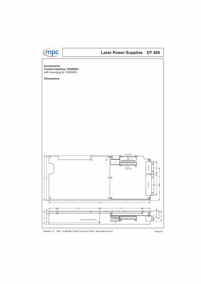
AccessoriesControl Interface 10228003with mounting kit 10228005
Dimensions
Release 1.0 2007 © Messtec Power Converter GmbH www.laserdriver.eu
Laser Power Supplies DT 400m c
Page 53
fastening screw thread M3 (3x)
34
23.5
6.5
21108.5108.521
26.219.912.6
259
11
5.4
11
3.5
44
39
.70
30.1
53.1
1
2
1 3 5 7 9 11
X5
1
2
X3
X4
Interlock Unit
DT 400 or
Control Panel
RS
232
Po
rtC
on
trolP
ort
X5
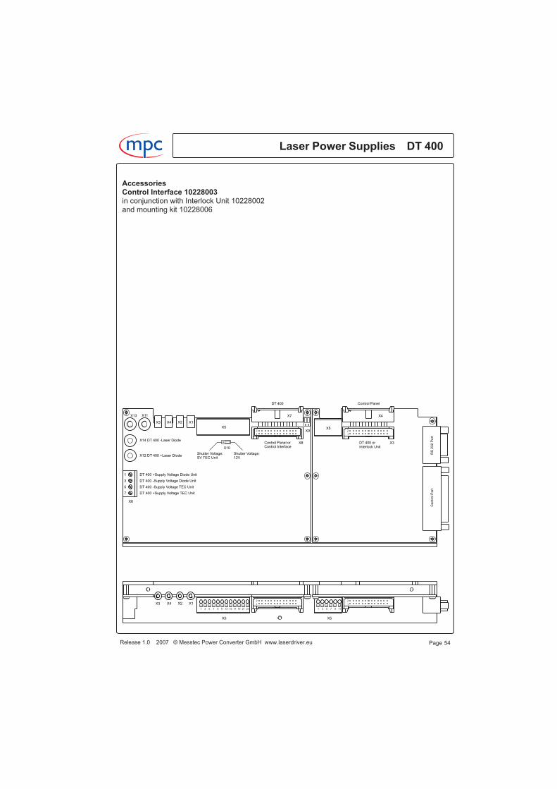
AccessoriesControl Interface 10228003in conjunction with Interlock Unit 10228002and mounting kit 10228006
Laser Power Supplies DT 400m c
Release 1.0 2007 © Messtec Power Converter GmbH www.laserdriver.eu Page 54
X5C
on
trolP
ort
RS
232
Po
rt
Control Panel
DT 400 orInterlock Unit
X4
X3
X5
1197531
2
1
2
1
X12
X14
SV TEC UnitShutter Voltage:
12VShutter Voltage:
Control InterfaceControl Panel or
DT 400
X5
DT 400 -Laser Diode
DT 400 +Laser Diode
7
5
3
1
DT 400 +Supply Voltage TEC Unit
DT 400 -Supply Voltage TEC Unit
DT 400 -Supply Voltage Diode Unit
DT 400 +Supply Voltage Diode Unit
X1X2X4X3
X13 X11
X3 X4 X2 X1
X5
X6
X10
X7
X8
X9
1
2
2321191715131197531
1
2

AccessoriesControl Interface 10228003
Termination block X5Spring-cage 6 pole termination block.Conductor cross section stranded minimum: 0.2 qmm,maximum: 1.5 qmm.
SV Control Interface pin 1, 3Input for supply voltage. The control interface has an isolated voltage converter on board, thisprevents from unwanted ground shifting.Supply voltage range: 15 V ... 50 V.If the control interface works in conjunction with the interlock unit, connect the supply voltageinputs to termination block X5 pin 1 and pin 3 at the interlock unit. Otherwise connect the supplyvoltage inputs to the power supply.See application 13 and 14 for further information.
Switch Local/Remote pin 9, 11Input for a local/remote switch, open contact means local, closed contact means remote.
LED Remote pin 5, 7Open emitter output for a LED, indicating remote operating mode. A LED can directly be connec-
ted, use a resistor of 220 Ohm in series�
If the control interface works in conjunction with a control panel 10227013, 10227014, 10227017or 10227018, the LED Remote and the LED GND must be connected to termination block X2 at
the control panel for indicating remote status. In this case a resistor is not required.
Header X3 and X4
X3, 26 pole header for connecting to DT 400 or to Interlock Unit 10228002.
X4, 26 pole header for connecting to a control panel.
Release 1.0 2007 © Messtec Power Converter GmbH www.laserdriver.eu
Laser Power Supplies DT 400m c
Page 55
Inputs
Pin Name Function
13911
+SV Control Interface-SV Control InterfaceSwitch Local/RemoteSwitch Local/Remote
+Suppy voltage-Suppy voltageSwitch Local/RemoteSwitch Local/Remote
Outputs
Pin Name Function
57
LED RemoteGND LED
LED Remote AnodeLED Remote Kathode

AccessoriesControl Interface 10228003Control Port25-pole female plug connector according toDIN 41652 and MIL-C-24308, female thread UNC 4-40.
CA=Control Data AnalogCD=Control Data DigitalSA=Status Data AnalogSD=Status Data Digital
Laser Power Supplies DT 400m c
Release 1.0 2007 © Messtec Power Converter GmbH www.laserdriver.eu Page 56
Control Port
Inputs
Pin Name Function
15236197114
CA-DCSPCA-DCLCA-PTSPCD-DCONCD-DCSDCD-PSDGNDGND
Diode Current Set PointDiode Current LimitPeltier Temperature Set PointDiode Current OnDiode Current Shut DownPeltier Voltage Shut DownSignal GroundSignal Ground
Outputs
Pin Name Function
416175182412251323820219221011114
SA-DCACTSA-DCSPLIMSA-DVACTSA-DPEACTSA-PTACTREFAUX+5VAUX+15VAUX-15VSD-READYSD-DCONSD-DCSDSD-PTLSD-PTHSD-PTISD-SILSD-REMGNDGND
Diode Current ActualDiode Current Set Point LimitedDiode Voltage ActualDiode Power Electrically ActualPeltier Temperature ActualReference VoltageAuxiliary Voltage +5 VAuxiliary Voltage +15 VAuxiliary Voltage -15 VReadyDiode Current OnDiode Current Shut DownPeltier Temperature LowPeltier Temperature HighPeltier Temperature InterlockSafety InterlockRemoteSignal GroundSignal Ground

AccessoriesControl Interface 10228003Control Port
Signal Description
CA-DCSPControl Analog - Diode Current Set PointAnalog input 0 ... +10.000 V for the current set point.+10.000 V corresponds to the maximum output current of the DT 400.
CA-DCLControl Analog - Diode Current LimitAnalog input 0 .... +10.000 V for the diode current limit.+10.000 V corresponds to the maximum output current of the DT 400.The diode current limit value is defined either by the value of the CA-DCL signal, the value of thenonvolatile memory (setup software), the value of the RS 232 software or by the setting of thediode current limit potentiometer at the DT 400.Turn current limit potentiometer at the DT 400 clockwise to it's maximum value if you would like todefine the current limit value by the CA-DCL signal, by memory or by RS 232.
CA-PTSPControl Analog - Peltier Temperature Set PointAnalog input 0 .... +10.000 V for a peltier temperature of 0 ... +50 °C.The peltier temperature set point is defined either by the value of the CA-PTSP signal, the value ofthe nonvolatile memory (setup software), the value of the RS 232 software or by the setting of thetemperature set point potentiometer at the DT 400.Turn temperature set point potentiometer at the DT 400 counterclockwise to it's minimum value ifyou would like to define the temperature set point by the CA-DCL signal, by memory or by RS 232.
CD-DCONControl Digital - Diode Current OnDigital input, active high. High turns diode current on, low turns off.
CD-DCSDControl Digital - Diode Current Shut DownDigital input, active high or active low, depends on configuration by setup software.Disables diode current.
CD-PSDControl Digital - Peltier Voltage Shut DownDigital input, active high. High turns the peltier voltage off.
SA-DCACTStatus Analog - Diode Current ActualAnalog output 0 ... +10.000 V, reflects the actual diode current.
SA-DCSPLIMStatus Analog - Diode Current Set Point LimitedAnalog output 0 ... +10.000 V, reflects the actual diode current set point, limited by the diode cur-rent limit value. The diode current limit value may be the CA-DCL signal, the value of the
Release 1.0 2007 © Messtec Power Converter GmbH www.laserdriver.eu
Laser Power Supplies DT 400m c
Page 57
Control Port
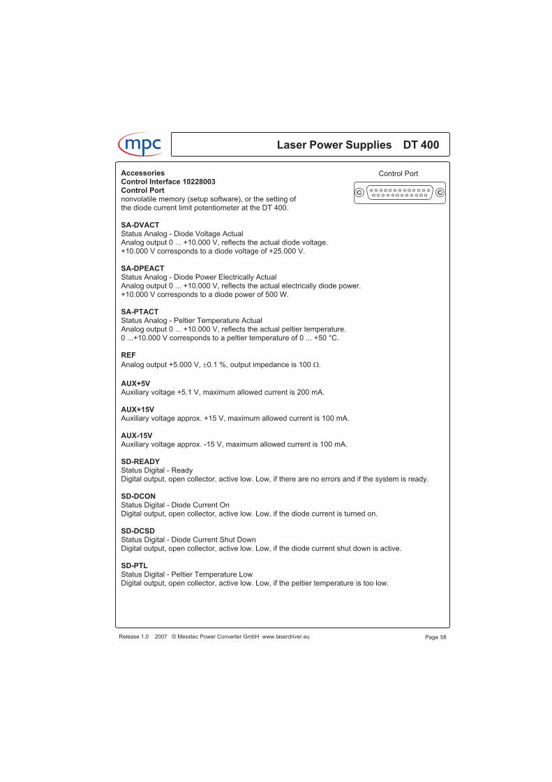
AccessoriesControl Interface 10228003Control Portnonvolatile memory (setup software), or the setting ofthe diode current limit potentiometer at the DT 400.
SA-DVACTStatus Analog - Diode Voltage ActualAnalog output 0 ... +10.000 V, reflects the actual diode voltage.+10.000 V corresponds to a diode voltage of +25.000 V.
SA-DPEACTStatus Analog - Diode Power Electrically ActualAnalog output 0 ... +10.000 V, reflects the actual electrically diode power.+10.000 V corresponds to a diode power of 500 W.
SA-PTACTStatus Analog - Peltier Temperature ActualAnalog output 0 ... +10.000 V, reflects the actual peltier temperature.0 ...+10.000 V corresponds to a peltier temperature of 0 ... +50 °C.
REF
Analog output +5.000 V, �0.1 %, output impedance is 100 ��
AUX+5VAuxiliary voltage +5.1 V, maximum allowed current is 200 mA.
AUX+15VAuxiliary voltage approx. +15 V, maximum allowed current is 100 mA.
AUX-15VAuxiliary voltage approx. -15 V, maximum allowed current is 100 mA.
SD-READYStatus Digital - ReadyDigital output, open collector, active low. Low, if there are no errors and if the system is ready.
SD-DCONStatus Digital - Diode Current OnDigital output, open collector, active low. Low, if the diode current is turned on.
SD-DCSDStatus Digital - Diode Current Shut DownDigital output, open collector, active low. Low, if the diode current shut down is active.
SD-PTLStatus Digital - Peltier Temperature LowDigital output, open collector, active low. Low, if the peltier temperature is too low.
Laser Power Supplies DT 400m c
Release 1.0 2007 © Messtec Power Converter GmbH www.laserdriver.eu Page 58
Control Port

AccessoriesControl Interface 10228003Control Port
SD-PTHStatus Digital - Peltier Temperature HighDigital output, open collector, active low. Low, if the peltier temperature is too high.
SD-PTIStatus Digital - Peltier Temperature InterlockDigital output, open collector, active low. Low, if there is a peltier temperature interlock.A peltier temperature interlock means, that the peltier temperature has exceededthe temperature supervision value due to excessive temperature.The temperature supervision value is defined either by the value of the nonvolatile memory (setupsoftware), or by the setting of the temperature interlock potentiometer at the DT 400.Turn temperature interlock potentiometer at the DT 400 clockwise to it's maximum value, if youwould like to define the supervision value by the setup software.
SD-SILStatus Digital - Safety InterlockDigital output, open collector, active low. Low, if an interlock occured.
SD-REMStatus Digital - RemoteDigital output, open collector, active low. Low, if the system works in the remote operating mode.
Digital signal levelsAll digital inputs can be operated by TTL, CMOS or any other logic levels up to +30 V.All digital outputs can drive up to 20 mA, the maximum permitted voltage is +30 V.
Release 1.0 2007 © Messtec Power Converter GmbH www.laserdriver.eu
Laser Power Supplies DT 400m c
Page 59
Control Port
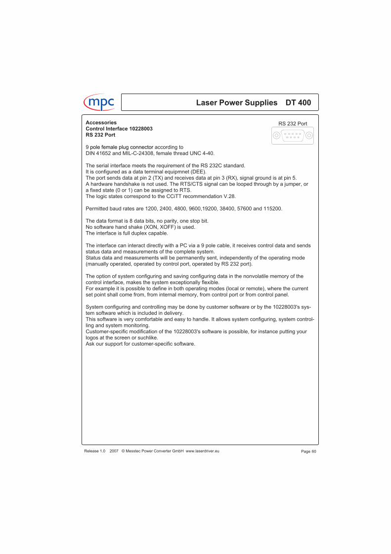
AccessoriesControl Interface 10228003RS 232 Port
9 pole female plug connector according toDIN 41652 and MIL-C-24308, female thread UNC 4-40.
The serial interface meets the requirement of the RS 232C standard.It is configured as a data terminal equipmnet (DEE).The port sends data at pin 2 (TX) and receives data at pin 3 (RX), signal ground is at pin 5.A hardware handshake is not used. The RTS/CTS signal can be looped through by a jumper, ora fixed state (0 or 1) can be assigned to RTS.The logic states correspond to the CCiTT recommendation V.28.
Permitted baud rates are 1200, 2400, 4800, 9600,19200, 38400, 57600 and 115200.
The data format is 8 data bits, no parity, one stop bit.No software hand shake (XON, XOFF) is used.The interface is full duplex capable.
The interface can interact directly with a PC via a 9 pole cable, it receives control data and sendsstatus data and measurements of the complete system.Status data and measurements will be permanently sent, independently of the operating mode(manually operated, operated by control port, operated by RS 232 port).
The option of system configuring and saving configuring data in the nonvolatile memory of thecontrol interface, makes the system exceptionally flexible.For example it is possible to define in both operating modes (local or remote), where the currentset point shall come from, from internal memory, from control port or from control panel.
System configuring and controlling may be done by customer software or by the 10228003's sys-tem software which is included in delivery.This software is very comfortable and easy to handle. It allows system configuring, system control-ling and system monitoring.Customer-specific modification of the 10228003's software is possible, for instance putting yourlogos at the screen or suchlike.Ask our support for customer-specific software.
Laser Power Supplies DT 400m c
Release 1.0 2007 © Messtec Power Converter GmbH www.laserdriver.eu Page 60
RS 232 Port

Install the 10228003's software and connect a PC at the RS 232 port.Turn on your system, start the program and select Set Up for configuring your system.Enter the required values at the Set Up panel, this values will be stored in the nonvolatile memoryof the control interface and will be relevant if memory is selected as a data source in the local orremote mode.The Diode Voltage Limit value does not really affect the output voltage of the DT 400, it is asupervision value which leads to a warning if exceeded. This is useful for detecting bad laserdiodes or bad contacts at the output lines.
For the TEC Temperature Interlock and the TEC Interlock Time Out, do not select low values.Consider that in most cases a thermal overshoot will occur if the system is turned on.Select whether the TEC Interlock Control shall be active or not. If you select active, the system willbe turned off after the TEC interlock time if there is excessive TEC temperature.
Select Shut Down Signal Polarity Low or High. If you select High, the diode current will be shutdown if the shut down signal is High.
Press the Confirm button, the values will be stored in the memory of the control interface.
Page 61Release 1.0 2007 © Messtec Power Converter GmbH www.laserdriver.eu
Laser Power Supplies DT 400m c
RS 232 PortAccessoriesControl Interface 10228003, RS 232 PortSystem software 10228003, Set Up
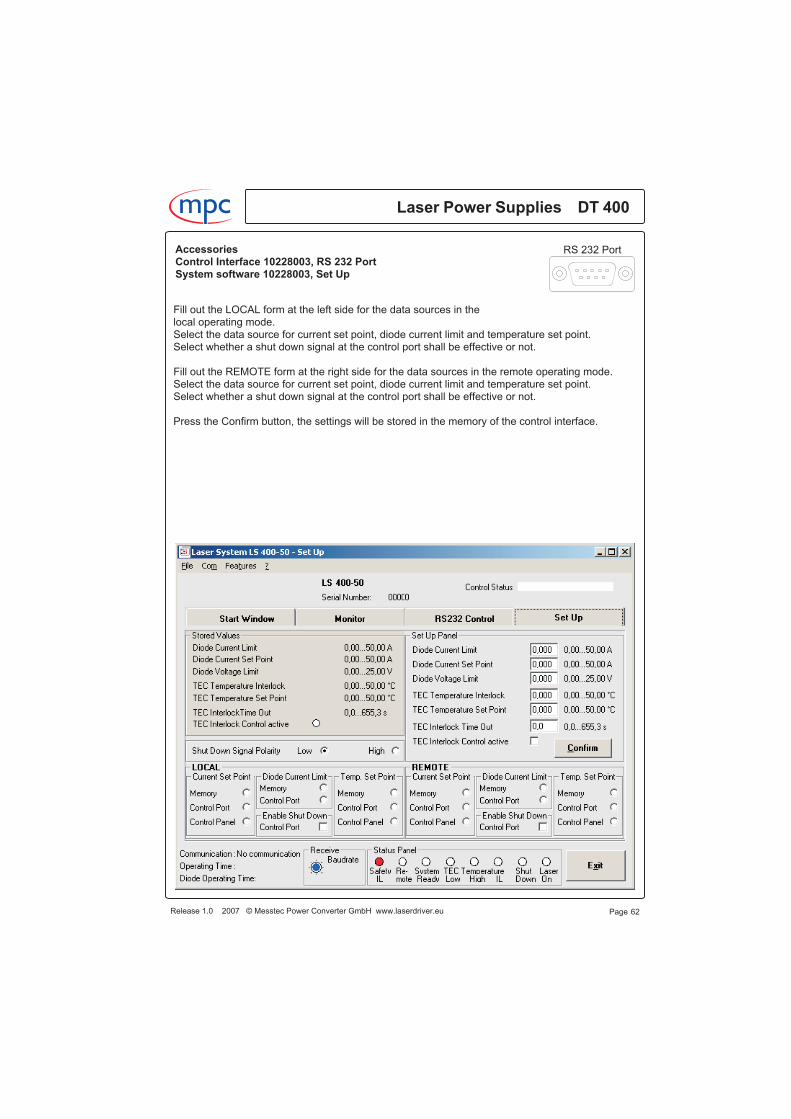
Fill out the LOCAL form at the left side for the data sources in thelocal operating mode.Select the data source for current set point, diode current limit and temperature set point.Select whether a shut down signal at the control port shall be effective or not.
Fill out the REMOTE form at the right side for the data sources in the remote operating mode.Select the data source for current set point, diode current limit and temperature set point.Select whether a shut down signal at the control port shall be effective or not.
Press the Confirm button, the settings will be stored in the memory of the control interface.
Laser Power Supplies DT 400m c
Release 1.0 2007 © Messtec Power Converter GmbH www.laserdriver.eu Page 62
RS 232 PortAccessoriesControl Interface 10228003, RS 232 PortSystem software 10228003, Set Up
Example for a Set Up:You plan a laser system which shall be operated manually and remote controlled. For the remoteoperating mode there is a programmable logic controller (PLC) at the control port which does'nthave analog outputs. Your laser has one diode, the diode current shall be 45,00 A, diode currentlimit shall be 46,50 A and temperature set point shall be 24,30 °C.
In the local operating mode, the current set point and the temperature set point shall be adjustedmanually for experimentation, a High shut down signal from the PLC shall be effective and shallturn off the diode current.
Turn on your system, start the program and select Set Up for configuring your system.At the Set Up panel enter 46,50 A for the diode current limit,enter 45,00 A for the diode current,enter 2,50 V for the diode voltage limit.
Enter 30,00 °C for the TEC temperature interlock,enter 24,30 °C for the temperature set point,enter 10,0 s for the TEC interlock time out.Select TEC interlock control active.
Select Shut Down Signal Polarity High at the left side.
Fill out the LOCAL form at the left side for the data sources in the local operating mode.Select Control Panel for the current set point,select Memory for the diode current limit,select Control Panel for the temperature set point.Select Enable Shut Down Control Port.
Fill out the REMOTE form at the right side for the data sources in the remote operating mode.Select Memory for the current set point,select Memory for the diode current limit,select Memory for the temperature set point.Select Enable Shut Down Control Port.
Press the Confirm button, the settings will be stored in the memory of the control interface and thesystem is ready for operating.
Release 1.0 2007 © Messtec Power Converter GmbH www.laserdriver.eu
Laser Power Supplies DT 400m c
Page 63
RS 232 PortAccessoriesControl Interface 10228003, RS 232 PortSystem software 10228003, Set Up

Example for a Set Up
Laser Power Supplies DT 400m c
Release 1.0 2007 © Messtec Power Converter GmbH www.laserdriver.eu Page 64
RS 232 PortAccessoriesControl Interface 10228003, RS 232 PortSystem software 10228003, Set Up

Select RS 232 Control for controlling the system by your PC.Enter the required values for diode current limit, diode current set point and TEC temperature setpoint at the RS 232 Control Panel.Select the data source for diode current limit, diode current set point and TEC temperature setpoint. Select whether a shut down signal at the control port shall be effective or not.If you select RS 232 for diode current limit, diode current set point and TEC temperature set point,the registered values at the RS 232 Control Panel will be relevant at operating.In other cases this values will be ignored.If you select Memory as a data source, the value registered in the memory (set up) will be relevantat operating.If you select Control Panel as a data source, the setting of the potentiometer at the control panelwill be relevant at operating.If you select Control Port as a data source, the analog set point signal fed in at the control port willbe relevant at operating, e.g. the diode current set point signal CA-DCSP.Every time you alter a value or a setting, you have to press the Confirm button.There are three buttons for operating, button ON, button OFF and TEC Shut Down.Button ON turns the laser on, button OFF turns the laser off.The button TEC Shut Down turns the TEC voltage off, this is useful for equipment testing.
Release 1.0 2007 © Messtec Power Converter GmbH www.laserdriver.eu
Laser Power Supplies DT 400m c
Page 65
RS 232 PortAccessoriesControl Interface 10228003, RS 232 PortSystem software 10228003, RS 232 Control
Status DataStatus data are splitted in three packets.
Packet P1 informs about measured values, current operating states and working hours.Packet P2 informs about data from control port and control panel.Packet P3 informs about stored data.
The short name of the data contains a data source number according to its origin.
Data source data source numberDT 400 1Control Port 2Control Panel 3Memory 4RS232 Port 5Control Interface 6
Control Byte SD6CONStatus Digital 6 ControlPacket P1, Packet P2 and Packet P3, respectively Byte 3.Reflects the current state of the control byte CD6CON.Contains the following status bits:
Reset Diode Working Hours SB6RDWHStatus Bit 6 Reset Diode Working HoursByte 3, Bit 1Reflects that the counter for the operating hours will be resetted. Reset will be done by control bitCB5RDWH with data source number 5.
Power Supply On SB6PSONStatus Bit 6 Power Supply OnByte 3, Bit 2Reflects that the DT 400 is in an on-state. On will be done by control bit CB5PSON of the RS 232port and /or by a CD-DCON signal at the control port or in the manual mode by a "ON" keystrokeat the control panel.
TEC Shut Down SB6TSDStatus Bit 6 TEC Shut DownByte 3, Bit 4Reflects that the TEC output is shut down. A TEC shut down will be done by control bit CB5TSD ofRS 232 port or by a CD-PSD signal at the control port.
Reboot Firmware SB6REBOOTStatus Bit 6 RebootByte 3, Bit 5Reflects that a restart of the control interface was activated. A restart will be done by
Laser Power Supplies DT 400m c
Release 1.0 2007 © Messtec Power Converter GmbH www.laserdriver.eu Page 66
RS 232 PortAccessoriesControl Interface 10228003, RS 232 PortSoftware Protocol
control bit CB5REBOOT of the RS 232 port.A restart is required if the system will be new configured.
Data Store SB6STOREStatus Bit 6 StoreByte 3, Bit 6Reflects that the data will be saved. Control bit CB5STORE must be set in the configuration dataset for saving data.
CD-DCON signal at the control port SB6CPPSONStatus Bit 6 Control Port Power Supply OnByte 3, Bit 7Reflects that the CD-DCON signal at the control port is High for turning on the DT 400.
Operating mode SD6OMStatus Digital 6 Operating ModePacket P1, Packet P2 und Packet P3, respectively Byte 4.Reflects the current state of control.
Operating Mode RS 232 SB6OMRSStatus Bit 6 Operating Mode RS 232Byte 4, Bit 1Reflects that the control interface is controlled by RS232.
Remote Mode Active SB6REMStatus Bit 6 Remote ModeByte 4, Bit 2Reflects that the remote mode of the control interface is active.
TEC Shut Down Active SB6TSDAStatus Bit 6 TEC Shut Down ActiveByte 4, Bit 4Reflects that the TEC shut down is active.
Receive RS 232 SB6RRSStatus Bit 6 Receive RS 232Byte 4, Bit 6Reflects that the control interface has received a byte from the RS 232 port.
Data Source Decoder SD6DECStatus Digital 6 Data Source DecoderPacket P1, Packet P2 und Packet P3, respectively Byte 5.Reflects the current assignments of the data sources.
Release 1.0 2007 © Messtec Power Converter GmbH www.laserdriver.eu
Laser Power Supplies DT 400m c
Page 67
RS 232 PortAccessoriesControl Interface 10228003, RS 232 PortSoftware Protocol

Data Source Decoder Local Mode SD4DECLOCStatus Digital 4 Data Source Decoder LocalPacket P3, Byte 23Reflects the settings of the decoder, which were configured with configuration byte CF5DECLOCand were stored.The settings of the decoder will be loaded from memory during local mode starting procedure.
Data Source Decoder Remote Mode SD4DECREMStatus Digital 4 Data Source Decoder RemotePacket P2, Byte 23Reflects the settings of the decoder, which were configured with configuration byte CF5DECREMand were stored.The settings of the decoder will be loaded from memory during remote mode starting procedure.
In Out Control SD6IOCStatus Digital 6 In Out ControlPacket P1, Packet P2 und Packet P3, respectively Byte 6.Reflects the settings of bits and contains the code of status data sets (transmit) and control datasets (receive). The code is mandatorily required.
Control Port Shut Down Enable SB6CPSDEStatus Bit 6 Control Port Shut Down EnableByte 6, Bit 0Reflects whether the shut down signal CD-DCSD at the control port is effective or not.
Shut Down Polarity Positive SB6SDPOLPStatus Bit 6 Shut Down Polarity PositiveByte 6, Bit 2Reflects whether a High shut down signal or a Low shut down signal results in a shut down.If bit 2 is 0, a Low signal results in a shut down, if bit 2 is 1, a High signal results in a shut down.This bit is effective in all control modes.
Temperature Control On SB6TCONStatus Bit 6 Temperature Control OnByte 6, Bit 3Reflects whether a temperature interlock is effective or not. If temperature interlock is active andan excessive temperature occures, the diode current will be turned off and error bit EB6TF will beset. This bit is effective in all control modes.
Code of received data setsByte 6 Bit 5 Bit 4 Data set name
0 0 Control data set0 1 Configuration data set1 0 Unused1 1 Short control data set
Laser Power Supplies DT 400m c
Release 1.0 2007 © Messtec Power Converter GmbH www.laserdriver.eu Page 68
RS 232 PortAccessoriesControl Interface 10228003, RS 232 PortSoftware Protocol
Code of transmitted data setsByte 6 Bit 7 Bit 6 Data set name
0 0 Status data set packet 10 1 Status data set packet 21 0 Status data set packet 31 1 Unused
In Out Control Local SD4IOCLOCStatus Digital 4 In Out Control LocalPacket P3, Byte 24.Reflects whether the shut down signal CD-DCSD at the control port is effective in the local modeor not. The setting is stored in SD4CPSDEL. The other bits aren’t significant.
In Out Control Remote Mode SD4IOCREMStatus Digital 4 In Out Control RemotePacket P2, Byte 24.Reflects whether the shut down signal CD-DCSD at the control port is effective in the remotemode or not. The setting is stored in bit SD4CPSDER. The other bits aren’t significant.
Error bitsPacket P1 in byte 8 and in byte10, respectively in the upper half byte.
Temperature Limit EB6TLError Bit 6 Temperature LimitPacket P1, Byte 8, Bit 4Bit 4 will be set if theTEC temperature interlock value will be exceeded. The diode current will beturned off.
RS 232 Data Fail EB6DFAILError Bit 6 Data FailPacket P1, Byte 8, Bit 5Bit 5 will be set if there is a data transfer error at the RS 232 port.
RS 232 Time Out EB6TOUTError Bit 6 Time OutPacket P1, Byte 8, Bit 6Bit 6 will be set if the RS 232 port doesn't receive data within the Time Out time. The diode currentwill be switched off. Bit 6 will be resetted if data will be received again, however the diode currentremains in an off-state.
RS232 Wrong Sign EB6WSError Bit 6 Wrong SignPacket P1, Byte 8, Bit 7Bit 7 will be set if a wrong character will be received. Bit 7 will be resetted if valid characters will bereceived again.
Release 1.0 2007 © Messtec Power Converter GmbH www.laserdriver.eu
Laser Power Supplies DT 400m c
Page 69
RS 232 PortAccessoriesControl Interface 10228003, RS 232 PortSoftware Protocol
Hardware Fault EB6HFAILError Bit 6 Hardware FaultPacket P1, Byte 10, Bit 4Bit 4 will be set if there is a hardware fault.
Voltage Limit EB6VLError Bit 6 Voltage LimitPacket P1, Byte 10, Bit 6Bit 6 will be set if the diode voltage exceeds the diode voltage supervision value.Bit 6 will be resetted if the diode voltage is lower than the diode voltage supervision value.
Decoder Fail EB6DECFError Bit 6 Data Source Decoder FailPacket P1, Byte 10, Bit 7Bit 7 will be set if the data source decoder gets an invalid value. In this case the diode currentcannot be turned on.
Operating mode bitsPacket P1 in byte 8 and in byte10, respectively in the upper half byte.
TEC Temperature Low SB6PTLStatus Bit 6 Peltier Temperature LowPacket P1, Byte 12, Bit 4Bit 4 will be set if the current TEC temperature is lower than the temperature set point.
TEC Temperature High SB6PTHStatus Bit 6 Peltier Temperature HighPacket P1, Byte 12, Bit 5Bit 5 will be set if the current TEC temperature is higher than the temperature set point.
Shut Down Active SB6SDAStatus Bit 6 Shut Down ActivePacket P1, Byte 12, Bit 6Bit 6 will be set if a shut down is active.
Power Supply On SB6PSONAStatus Bit 6 Power Supply OnPacket P1, Byte 12, Bit 7Bit 7 will be set if the DT 400 is turned on.
Power Supply Ready SB6PSRStatus Bit 6 Power Supply ReadyPacket P1, Byte 14, Bit 4Bit 4 will be set if the DT 400 is ready for operating.
Laser Power Supplies DT 400m c
Release 1.0 2007 © Messtec Power Converter GmbH www.laserdriver.eu Page 70
RS 232 PortAccessoriesControl Interface 10228003, RS 232 PortSoftware Protocol
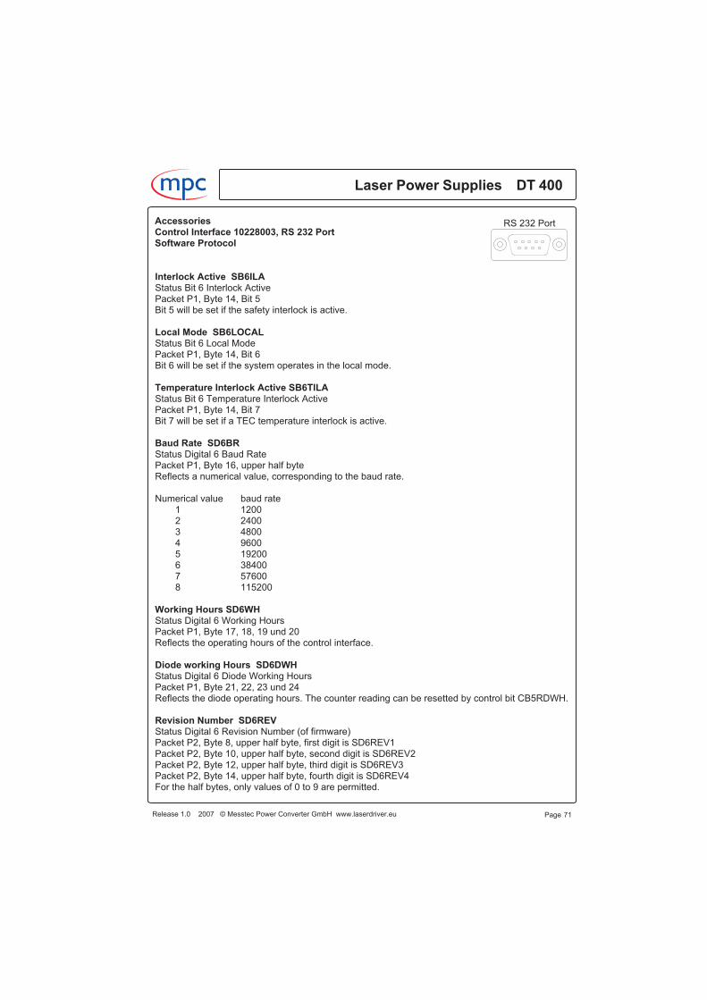
Interlock Active SB6ILAStatus Bit 6 Interlock ActivePacket P1, Byte 14, Bit 5Bit 5 will be set if the safety interlock is active.
Local Mode SB6LOCALStatus Bit 6 Local ModePacket P1, Byte 14, Bit 6Bit 6 will be set if the system operates in the local mode.
Temperature Interlock Active SB6TILAStatus Bit 6 Temperature Interlock ActivePacket P1, Byte 14, Bit 7Bit 7 will be set if a TEC temperature interlock is active.
Baud Rate SD6BRStatus Digital 6 Baud RatePacket P1, Byte 16, upper half byteReflects a numerical value, corresponding to the baud rate.
Numerical value baud rate1 12002 24003 48004 96005 192006 384007 576008 115200
Working Hours SD6WHStatus Digital 6 Working HoursPacket P1, Byte 17, 18, 19 und 20Reflects the operating hours of the control interface.
Diode working Hours SD6DWHStatus Digital 6 Diode Working HoursPacket P1, Byte 21, 22, 23 und 24Reflects the diode operating hours. The counter reading can be resetted by control bit CB5RDWH.
Revision Number SD6REVStatus Digital 6 Revision Number (of firmware)Packet P2, Byte 8, upper half byte, first digit is SD6REV1Packet P2, Byte 10, upper half byte, second digit is SD6REV2Packet P2, Byte 12, upper half byte, third digit is SD6REV3Packet P2, Byte 14, upper half byte, fourth digit is SD6REV4For the half bytes, only values of 0 to 9 are permitted.
Release 1.0 2007 © Messtec Power Converter GmbH www.laserdriver.eu
Laser Power Supplies DT 400m c
Page 71
RS 232 PortAccessoriesControl Interface 10228003, RS 232 PortSoftware Protocol
The revision number of the firmware results of:SD6REV = SD6REV4 + SD6REV3 + SD6REV2 + SD6REV1Example for a revision number: 0109
Last Fault SD6LFStatus Digital 6 Last FaultPacket P2, Byte 16, upper half byteReflects the error number of the last fault.
Error number Error1 Temperature interlock2 Decoder error3 Communication error4 RS232 port data fail5 RS232 port wrong sign6 Hardware fail7 Voltage supervision value exceeded
Serial number SD6SNStatus Digital 6 Serial NumberPacket P3, Byte 7 and 8Reflects the serial number of the control interface.
Time Out RS 232 port SD4TOUTStatus Digital 4 Time Out RS232 PortPacket P3, Byte 9 and 10Reflects the Time Out value of the RS 232 port.The Time Out value is determined by the configuration word CFT5TOUT, the value is stored in thememory of the control interface.
Time Out Temperature Control SD4TOTCStatus Digital 4 Time Out Temperature ControlPacket P3, Byte 21 and 22Reflects the Time Out value of the temperature control.The Time Out value is determined by the configuration word CFT5TOTC, the value is stored in thememory of the control interface.
Diode Current Set Point Limited SA1DCSPLStatus Analog 1 Diode Current Set Point LimitedPacket P1, Byte 7 and lower half byte of byte 8Reflects the actual diode current set point, limited by the diode current limit value. The diodecurrent limit value may be the CA-DCL signal of the control port, the value of the nonvolatilememory (setup software), or the setting of the diode current limit potentiometer at the DT 400.
Laser Power Supplies DT 400
Page 72
m c
Release 1.0 2007 © Messtec Power Converter GmbH www.laserdriver.eu
RS 232 PortAccessoriesControl Interface 10228003, RS 232 PortSoftware Protocol
Diode Current Actual SA1DCACTStatus Analog 1 Diode Current ActualPacket P1, Byte 9 and lower half byte of byte10Reflects the actual diode current.
Diode Voltage Actual SA1DVACTStatus Analog 1 Diode Voltage ActualPacket P1, Byte 11 and lower half byte of byte12Reflects the actual diode voltage.
Diode Current Set Point 2 SA3DCSP2Status Analog 3 Diode Current Set Point 2Packet P1, Byte 13 and lower half byte of byte14Reflects the diode current set point signal at X3 of a control panel.Not implemented.
TEC Temperature Actual SA1PTACTStatus Analog 1 Peltier Temperature ActualPacket P1, Byte 15 and lower half byte of byte16Reflects the actual TEC temperature.
Diode Current Limit SA2DCLStatus Analog 2 Diode Current LimitPacket P2, Byte 7 and lower half byte of byte 8Reflects the diode current limit signal CA-DCL at the control port.
Diode Current Set Point SA2DCSPStatus Analog 2 Diode Current Set PointPacket P2, Byte 11 and lower half byte of byte 12Reflects the diode current set point signal CA-DCSP at the control port.
TEC Temperature Set Point SA2PTSPStatus Analog 2 Peltier Temperature Set PointPacket P2, Byte 17 and lower half byte of byte 18Reflects the Peltier temperature set point signal CA-PTSP at the control port.
Diode Current Set Point SA3DCSPStatus Analog 3 Diode Current Set Point Control PanelPacket P2, Byte 13 and lower half byte of byte 14Reflects the diode current set point of a control panel.
TEC Temperature Set Point SA3PTSPStatus Analog 3 Peltier Temperature Set Point Control PanelPacket P2, Byte 19 and lower half byte of byte 20Reflects the Peltier temperature set point of a control panel.
Page 73Release 1.0 2007 © Messtec Power Converter GmbH www.laserdriver.eu
Laser Power Supplies DT 400m c
RS 232 PortAccessoriesControl Interface 10228003, RS 232 PortSoftware Protocol

Diode Current Set Point SD4DCSPStatus Digital 4 Diode Current Set Point MemoryPacket P2, Byte 15 and lower half byte of byte 16Packet P3, Byte 11 and lower half byte of byte 12Reflects the diode current set point stored in the memory.
Diode Current Limit SD4DCLStatus Digital 4 Diode Current Limit MemoryPacket P2, Byte 9 and lower half byte of byte 10Packet P3, Byte 13 and lower half byte of byte 14Reflects the diode current limit stored in the memory.
TEC Temperature Set Point SD4PTSPStatus Digital 4 Peltier Temperature Set Point MemoryPacket P2, Byte 21 and lower half byte of byte 22Packet P3, Byte 15 and lower half byte of byte 16Reflects the Peltier temperature set point stored in the memory.
TEC Temperature Interlock CD4PTLControl Digital 4 Peltier Temperature InterlockPacket P3, Byte 17 and lower half byte of byte 18Reflects the Peltier temperature interlock value stored in the memory.
Diode Voltage Limit CD4DVLControl Digital 4 Diode Voltage Limit MemoryPacket P3, Byte 19 and lower half byte of byte 20Reflects the diode voltage limit value stored in the memory.
Laser Power Supplies DT 400
Page 74
m c
Release 1.0 2007 © Messtec Power Converter GmbH www.laserdriver.eu
RS 232 PortAccessoriesControl Interface 10228003, RS 232 PortSoftware Protocol
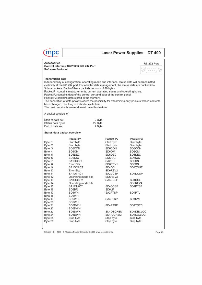
Transmitted dataIndependently of configuration, operating mode and interface, status data will be transmittedcyclically at the RS 232 port. For a better data management, the status data are packed into3 data packets. Each of these packets consists of 26 bytes.Packet P1 contains measurements, current operating states and operating hours.Packet P2 contains data of the control port and data of the control panel.Packet P3 contains data stored in the memory.The separation of data packets offers the possibility for transmitting only packets whose contentshave changed, resulting in a shorter cycle time.The basic version however doesn't have this feature.
A packet consists of:
Start of data set 2 ByteStatus data bytes 22 ByteEnd of data set 2 Byte
Status data packet overview
Packet P1 Packet P2 Packet P3Byte 1 Start byte Start byte Start byteByte 2 Start byte Start byte Start byteByte 3 SD6CON SD6CON SD6CONByte 4 SD6OM SD6OM SD6OMByte 5 SD6DEC SD6DEC SD6DECByte 6 SD6IOC SD6IOC SD6IOCByte 7 SA1DCSPL SA2DCL SD6SNByte 8 Error Bits SD6REV1 SD6SNByte 9 SA1DCACT SD4DCL SD4TOUTByte 10 Error Bits SD6REV2Byte 11 SA1DVACT SA2DCSP SD4DCSPByte 12 Operating mode bits SD6REV3Byte 13 SA3DCSP2 SA3DCSP SD4DCLByte 14 Operating mode bits SD6REV4Byte 15 SA1PTACT SD4DCSP SD4PTSPByte 16 SD6BR SD6LFByte 17 SD6WH SA2PTSP SD4PTLByte 18 SD6WHByte 19 SD6WH SA3PTSP SD4DVLByte 20 SD6WHByte 21 SD6DWH SD4PTSP SD4TOTCByte 22 SD6DWHByte 23 SD6DWH SD4DECREM SD4DECLOCByte 24 SD6DWH SD4IOCREM SD4IOCLOCByte 25 Stop byte Stop byte Stop byteByte 26 Stop byte Stop byte Stop byte
Page 75Release 1.0 2007 © Messtec Power Converter GmbH www.laserdriver.eu
Laser Power Supplies DT 400m c
RS 232 PortAccessoriesControl Interface 10228003, RS 232 PortSoftware Protocol

Description packet P1Packet P1 contains measurements, current operating states and operating hours.
Packet P1 status byte 1 start bytePacket P1 status byte 2 start byteFor starting the sequence a start byte will be send twice.The start byte must have a hexadecimal value of “0A” or a binary value of “0000 1010”.
Packet P1 status byte 3 control byte SD6CON8 bit word, binary output, reflects the current operating state.
Bit 0 Unused.Bit 1 = 1 SB6RDWH Counter for diode operating hours is reset.Bit 2 = 1 SB6PSON DT 400 is in on-state.Bit 3 Unused.Bit 4 = 1 SB6TSD TEC shut down is active.Bit 5 = 1 SB6REBOOT System reboot was triggered.Bit 6 = 1 SB6STORE Data are saved.Bit 7 = 1 SB6CPPSON DT 400 is turned on by CD-DCON-signal at the control port.
Packet P1 status byte 4 operating state byte SD6OM8 bit word, binary output, reflects the current operating mode.
Bit 0 Unused.Bit 1 = 1 SB6OMRS RS232 port is used for control.Bit 2 Unused.Bit 3 = 1 SB6REM Remote mode is active.Bit 4 = 1 SB6TSDA TEC shut down is active.Bit 5 Unused.Bit 6 = 1 SB6RRS Data were received of RS 232 port.Bit 7 Unused.
Packet P1 status byte 5 data source decoder SD6DEC8 bit word, binary output, reflects the data source assignments.
Bit 1 Bit 00 0 The diode current limit value is given by RS 232 port.0 1 The diode current limit value is given by memory.1 0 The diode current limit value is given by control port.
Bit 4 Bit 3 Bit 20 0 0 The diode current set point is given by RS 232 port.0 0 1 The diode current set point is given by memory.0 1 0 The diode current set point is given control port.1 0 0 The diode current set point is given by control panel.
Laser Power Supplies DT 400
Page 76
m c
Release 1.0 2007 © Messtec Power Converter GmbH www.laserdriver.eu
RS 232 PortAccessoriesControl Interface 10228003, RS 232 PortSoftware Protocol
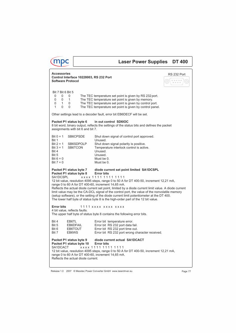
Bit 7 Bit 6 Bit 50 0 0 The TEC temperature set point is given by RS 232 port.0 0 1 The TEC temperature set point is given by memory.0 1 0 The TEC temperature set point is given by control port.1 0 0 The TEC temperature set point is given by control panel.
Other settings lead to a decoder fault, error bit EB6DECF will be set.
Packet P1 status byte 6 in out control SD6lOC8 bit word, binary output, reflects the settings of the status bits and defines the packetassignments with bit 6 and bit 7.
Bit 0 = 1 SB6CPSDE Shut down signal of control port approved.Bit 1 Unused.Bit 2 = 1 SB6SDPOLP Shut down signal polarity is positive.Bit 3 = 1 SB6TCON Temperature interlock control is active.Bit 4 Unused.Bit 5 Unused.Bit 6 = 0 Must be 0.Bit 7 = 0 Must be 0.
Packet P1 status byte 7 diode current set point limited SA1DCSPLPacket P1 status byte 8 Error bitsSA1DCSPL x x x x 1 1 1 1 1 1 1 1 1 1 1 112 bit value, resolution 4095 steps, range 0 to 50 A for DT 400-50, increment 12,21 mA,range 0 to 60 A for DT 400-60, increment 14,65 mA.Reflects the actual diode current set point, limited by a diode current limit value. A diode currentlimit value may be the CA-DCL signal of the control port, the value of the nonvolatile memory(setup software), or the setting of the diode current limit potentiometer at the DT 400.The lower half byte of status byte 8 is the high-order part of the 12 bit value.
Error bits 1 1 1 1 x x x x x x x x x x x x4 bit value, reflects faults.The upper half byte of status byte 8 contains the following error bits.
Bit 4 EB6TL Error bit temperature error.Bit 5 EB6DFAIL Error bit RS 232 port data fail.Bit 6 EB6TOUT Error bit RS 232 port time out.Bit 7 EB6WS Error bit RS 232 port wrong character received.
Packet P1 status byte 9 diode current actual SA1DCACTPacket P1 status byte 10 Error bitsSA1DCACT x x x x 1 1 1 1 1 1 1 1 1 1 1 112 bit value, resolution 4095 steps, range 0 to 50 A for DT 400-50, increment 12,21 mA,range 0 to 60 A for DT 400-60, increment 14,65 mA.Reflects the actual diode current.
Page 77Release 1.0 2007 © Messtec Power Converter GmbH www.laserdriver.eu
Laser Power Supplies DT 400m c
RS 232 PortAccessoriesControl Interface 10228003, RS 232 PortSoftware Protocol
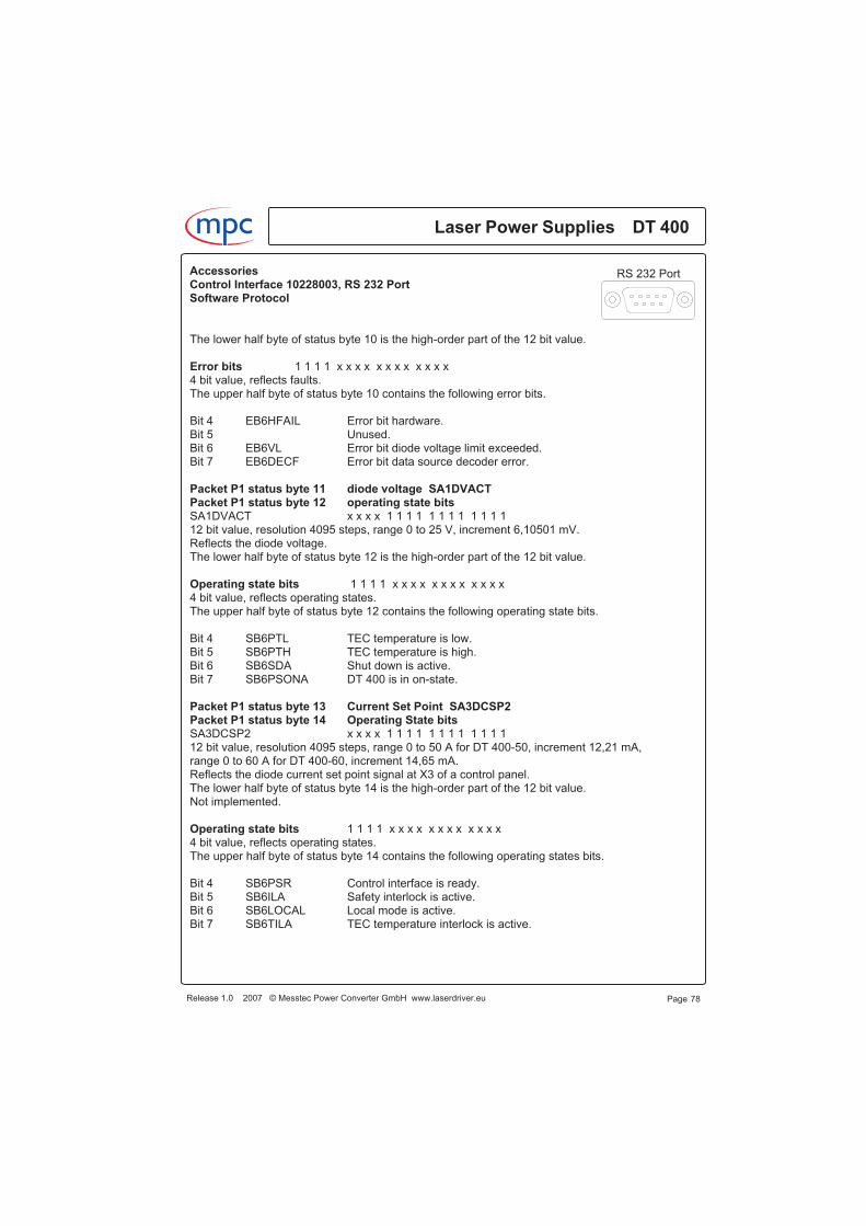
The lower half byte of status byte 10 is the high-order part of the 12 bit value.
Error bits 1 1 1 1 x x x x x x x x x x x x4 bit value, reflects faults.The upper half byte of status byte 10 contains the following error bits.
Bit 4 EB6HFAIL Error bit hardware.Bit 5 Unused.Bit 6 EB6VL Error bit diode voltage limit exceeded.Bit 7 EB6DECF Error bit data source decoder error.
Packet P1 status byte 11 diode voltage SA1DVACTPacket P1 status byte 12 operating state bitsSA1DVACT x x x x 1 1 1 1 1 1 1 1 1 1 1 112 bit value, resolution 4095 steps, range 0 to 25 V, increment 6,10501 mV.Reflects the diode voltage.The lower half byte of status byte 12 is the high-order part of the 12 bit value.
Operating state bits 1 1 1 1 x x x x x x x x x x x x4 bit value, reflects operating states.The upper half byte of status byte 12 contains the following operating state bits.
Bit 4 SB6PTL TEC temperature is low.Bit 5 SB6PTH TEC temperature is high.Bit 6 SB6SDA Shut down is active.Bit 7 SB6PSONA DT 400 is in on-state.
Packet P1 status byte 13 Current Set Point SA3DCSP2Packet P1 status byte 14 Operating State bitsSA3DCSP2 x x x x 1 1 1 1 1 1 1 1 1 1 1 112 bit value, resolution 4095 steps, range 0 to 50 A for DT 400-50, increment 12,21 mA,range 0 to 60 A for DT 400-60, increment 14,65 mA.Reflects the diode current set point signal at X3 of a control panel.The lower half byte of status byte 14 is the high-order part of the 12 bit value.Not implemented.
Operating state bits 1 1 1 1 x x x x x x x x x x x x4 bit value, reflects operating states.The upper half byte of status byte 14 contains the following operating states bits.
Bit 4 SB6PSR Control interface is ready.Bit 5 SB6ILA Safety interlock is active.Bit 6 SB6LOCAL Local mode is active.Bit 7 SB6TILA TEC temperature interlock is active.
Laser Power Supplies DT 400
Page 78
m c
Release 1.0 2007 © Messtec Power Converter GmbH www.laserdriver.eu
RS 232 PortAccessoriesControl Interface 10228003, RS 232 PortSoftware Protocol
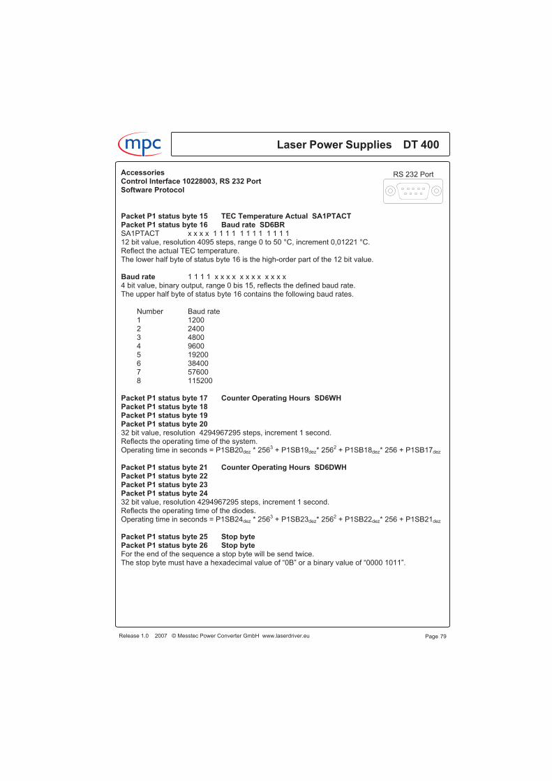
Packet P1 status byte 15 TEC Temperature Actual SA1PTACTPacket P1 status byte 16 Baud rate SD6BRSA1PTACT x x x x 1 1 1 1 1 1 1 1 1 1 1 112 bit value, resolution 4095 steps, range 0 to 50 °C, increment 0,01221 °C.Reflect the actual TEC temperature.The lower half byte of status byte 16 is the high-order part of the 12 bit value.
Baud rate 1 1 1 1 x x x x x x x x x x x x4 bit value, binary output, range 0 bis 15, reflects the defined baud rate.The upper half byte of status byte 16 contains the following baud rates.
Number Baud rate1 12002 24003 48004 96005 192006 384007 576008 115200
Packet P1 status byte 17 Counter Operating Hours SD6WHPacket P1 status byte 18Packet P1 status byte 19Packet P1 status byte 2032 bit value, resolution 4294967295 steps, increment 1 second.Reflects the operating time of the system.Operating time in seconds = P1SB20dez * 256
3+ P1SB19dez* 256
2+ P1SB18dez* 256 + P1SB17dez
Packet P1 status byte 21 Counter Operating Hours SD6DWHPacket P1 status byte 22Packet P1 status byte 23Packet P1 status byte 2432 bit value, resolution 4294967295 steps, increment 1 second.Reflects the operating time of the diodes.Operating time in seconds = P1SB24dez * 256
3+ P1SB23dez* 256
2+ P1SB22dez* 256 + P1SB21dez
Packet P1 status byte 25 Stop bytePacket P1 status byte 26 Stop byteFor the end of the sequence a stop byte will be send twice.The stop byte must have a hexadecimal value of “0B” or a binary value of “0000 1011”.
Release 1.0 2007 © Messtec Power Converter GmbH www.laserdriver.eu
Laser Power Supplies DT 400m c
Page 79
RS 232 PortAccessoriesControl Interface 10228003, RS 232 PortSoftware Protocol
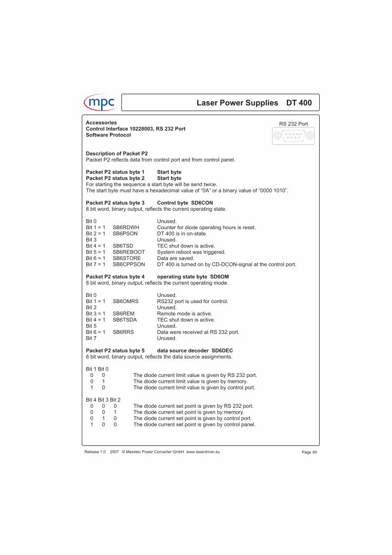
Description of Packet P2Packet P2 reflects data from control port and from control panel.
Packet P2 status byte 1 Start bytePacket P2 status byte 2 Start byteFor starting the sequence a start byte will be send twice.The start byte must have a hexadecimal value of “0A” or a binary value of “0000 1010”.
Packet P2 status byte 3 Control byte SD6CON8 bit word, binary output, reflects the current operating state.
Bit 0 Unused.Bit 1 = 1 SB6RDWH Counter for diode operating hours is reset.Bit 2 = 1 SB6PSON DT 400 is in on-state.Bit 3 Unused.Bit 4 = 1 SB6TSD TEC shut down is active.Bit 5 = 1 SB6REBOOT System reboot was triggered.Bit 6 = 1 SB6STORE Data are saved.Bit 7 = 1 SB6CPPSON DT 400 is turned on by CD-DCON-signal at the control port.
Packet P2 status byte 4 operating state byte SD6OM8 bit word, binary output, reflects the current operating mode.
Bit 0 Unused.Bit 1 = 1 SB6OMRS RS232 port is used for control.Bit 2 Unused.Bit 3 = 1 SB6REM Remote mode is active.Bit 4 = 1 SB6TSDA TEC shut down is active.Bit 5 Unused.Bit 6 = 1 SB6RRS Data were received at RS 232 port.Bit 7 Unused.
Packet P2 status byte 5 data source decoder SD6DEC8 bit word, binary output, reflects the data source assignments.
Bit 1 Bit 00 0 The diode current limit value is given by RS 232 port.0 1 The diode current limit value is given by memory.1 0 The diode current limit value is given by control port.
Bit 4 Bit 3 Bit 20 0 0 The diode current set point is given by RS 232 port.0 0 1 The diode current set point is given by memory.0 1 0 The diode current set point is given by control port.1 0 0 The diode current set point is given by control panel.
Laser Power Supplies DT 400
Page 80
m c
Release 1.0 2007 © Messtec Power Converter GmbH www.laserdriver.eu
RS 232 PortAccessoriesControl Interface 10228003, RS 232 PortSoftware Protocol
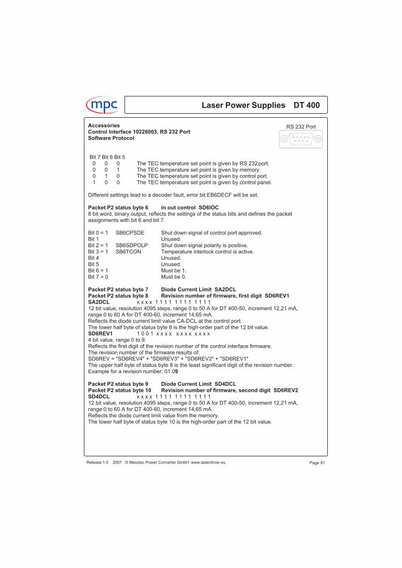
Bit 7 Bit 6 Bit 50 0 0 The TEC temperature set point is given by RS 232 port.0 0 1 The TEC temperature set point is given by memory.0 1 0 The TEC temperature set point is given by control port.1 0 0 The TEC temperature set point is given by control panel.
Different settings lead to a decoder fault, error bit EB6DECF will be set.
Packet P2 status byte 6 in out control SD6lOC8 bit word, binary output, reflects the settings of the status bits and defines the packetassignments with bit 6 and bit 7.
Bit 0 = 1 SB6CPSDE Shut down signal of control port approved.Bit 1 Unused.Bit 2 = 1 SB6SDPOLP Shut down signal polarity is positive.Bit 3 = 1 SB6TCON Temperature interlock control is active.Bit 4 Unused.Bit 5 Unused.Bit 6 = 1 Must be 1.Bit 7 = 0 Must be 0.
Packet P2 status byte 7 Diode Current Limit SA2DCLPacket P2 status byte 8 Revision number of firmware, first digit SD6REV1SA2DCL x x x x 1 1 1 1 1 1 1 1 1 1 1 112 bit value, resolution 4095 steps, range 0 to 50 A for DT 400-50, increment 12,21 mA,range 0 to 60 A for DT 400-60, increment 14,65 mA.Reflects the diode current limit value CA-DCL at the control port.The lower half byte of status byte 8 is the high-order part of the 12 bit value.SD6REV1 1 0 0 1 x x x x x x x x x x x x4 bit value, range 0 to 9.Reflects the first digit of the revision number of the control interface firmware.The revision number of the firmware results of:SD6REV = "SD6REV4" + "SD6REV3" + "SD6REV2" + "SD6REV1"The upper half byte of status byte 8 is the least significant digit of the revision number.Example for a revision number: 01.09
Packet P2 status byte 9 Diode Current Limit SD4DCLPacket P2 status byte 10 Revision number of firmware, second digit SD6REV2SD4DCL x x x x 1 1 1 1 1 1 1 1 1 1 1 112 bit value, resolution 4095 steps, range 0 to 50 A for DT 400-50, increment 12,21 mA,range 0 to 60 A for DT 400-60, increment 14,65 mA.Reflects the diode current limit value from the memory.The lower half byte of status byte 10 is the high-order part of the 12 bit value.
Release 1.0 2007 © Messtec Power Converter GmbH www.laserdriver.eu
Laser Power Supplies DT 400m c
Page 81
RS 232 PortAccessoriesControl Interface 10228003, RS 232 PortSoftware Protocol
SD6REV2 0 0 0 0 x x x x x x x x x x x x4 bit value, range 0 to 9.Reflects the second digit of the revision number of the control interface firmware.The revision number of the firmware results of:SD6REV = "SD6REV4" + "SD6REV3" + "SD6REV2" + "SD6REV1"The upper half byte of status byte 10 is the most significant digit after the dot.Example for a revision number: 01.09
Packet P2 status byte 11 Diode Current Set Point SD2DCSPPacket P2 status byte 12 Revision number of firmware, third digit SD6REV3SD2DCSP x x x x 1 1 1 1 1 1 1 1 1 1 1 112 bit value, resolution 4095 steps, range 0 to 50 A for DT 400-50, increment 12,21 mA,range 0 to 60 A for DT 400-60, increment 14,65 mA.Reflects the diode current set point CA-DCSP at the control port.The lower half byte of status byte 12 is the high-order part of the 12 bit value.SD6REV3 0 0 0 1 x x x x x x x x x x x x4 bit value, range 0 to 9.Reflects the third digit of the revision number of the control interface firmware.The revision number of the firmware results of:SD6REV = "SD6REV4" + "SD6REV3" + "SD6REV2" + "SD6REV1"The upper half byte of status byte 12 is the least significant digit left of the dot.Example for a revision number: 01.09
Packet P2 status byte 13 Diode Current Set Point SA3DCSPPacket P2 status byte 14 Revision number of firmware, fourth digit SD6REV4SA3DCSP x x x x 1 1 1 1 1 1 1 1 1 1 1 112 bit value, resolution 4095 steps, range 0 to 50 A for DT 400-50, increment 12,21 mA,range 0 to 60 A for DT 400-60, increment 14,65 mA.Reflects the diode current set point at the control panel.The lower half byte of status byte 14 is the high-order part of the 12 bit value.SD6REV4 0 0 0 0 x x x x x x x x x x x x4 bit value, range 0 to 9.Reflects the fourth digit of the revision number of the control interface firmware.The revision number of the firmware results of:SD6REV = "SD6REV4" + "SD6REV3" + "SD6REV2" + "SD6REV1"The upper half byte of status byte 14 is the most significant digit left of the dot.Example for a revision number: 01.09
Packet P2 status byte 15 Diode Current Set Point in memory SD4DCSPPacket P2 status byte 16 Number of last faults SD6LFSD4DCSP x x x x 1 1 1 1 1 1 1 1 1 1 1 112 bit value, resolution 4095 steps, range 0 to 50 A for DT 400-50, increment 12,21 mA,range 0 to 60 A for DT 400-60, increment 14,65 mA.Reflects the diode current set point of the memory.The lower half byte of status byte 16 is the high-order part of the 12 bit value.
Laser Power Supplies DT 400
Page 82
m c
Release 1.0 2007 © Messtec Power Converter GmbH www.laserdriver.eu
RS 232 PortAccessoriesControl Interface 10228003, RS 232 PortSoftware Protocol

SD6LF 1 1 1 1 x x x x x x x x x x x x4 bit value, range 0 to15.The upper half byte of status byte 16 contains the number of the last faults.
Fault number Fault name1 TEC temperature fault.2 Decoder error.3 Communication error.4 RS 232 port data fail.5 RS 232 port wrong character received.6 Hardware fail.7 Diode voltage limit exceeded.
Packet P2 status byte 17 TEC Temperature Set Point SA2PTSPPacket P2 status byte 18SA2PTSP x x x x 1 1 1 1 1 1 1 1 1 1 1 112 bit value, resolution 4095 steps, range 0 to 50°C, increment 0,01221°C.Reflects the TEC temperature set point CA-PTSP at the control port.The lower half byte of status byte 18 is the high-order part of the 12 bit value.The high-order half byte of status byte 18 is unused.
Packet P2 status byte 19 TEC Temperature Set Point SA3PTSPPacket P2 status byte 20SA3PTSP x x x x 1 1 1 1 1 1 1 1 1 1 1 112 bit value, resolution 4095 steps, range 0 to 50 °C, increment 0,01221 °C.Reflects the TEC temperature set point of the control panel.The lower half byte of status byte 20 is the high-order part of the 12 bit value.The high-order half byte of status byte 20 is unused.
Packet P2 status byte 21 TEC Temperature Set Point SD4PTSPPacket P2 status byte 22SD4PTSP x x x x 1 1 1 1 1 1 1 1 1 1 1 112 bit value, resolution 4095 steps, range 0 to 50 °C, increment 0,01221 °C.Reflects the TEC temperature set point stored in the memory.The lower half byte of status byte 22 is the high-order part of the 12 bit value.The high-order half byte of status byte 22 is unused.
Packet P2 status byte 23 Data Source Decoder Remote SD4DECREM8 bit word, binary output, reflects the data source assignments for the remote mode.
Bit 1 Bit 00 0 The diode current limit value is given by RS 232 port.0 1 The diode current limit value is given by memory.1 0 The diode current limit value is given by control port.
Page 83Release 1.0 2007 © Messtec Power Converter GmbH www.laserdriver.eu
Laser Power Supplies DT 400m c
RS 232 PortAccessoriesControl Interface 10228003, RS 232 PortSoftware Protocol

Packet P2 status byte 23 Data Source Decoder Remote SD4DECREM
Bit 4 Bit 3 Bit 20 0 0 The diode current set point is given by RS 232 port.0 0 1 The diode current set point is given by memory.0 1 0 The diode current set point is given by control port.1 0 0 The diode current set point is given by control panel.
Bit 7 Bit 6 Bit 50 0 0 The TEC temperature set point is given by RS 232 port.0 0 1 The TEC temperature set point is given by memory.0 1 0 The TEC temperature set point is given by control port.1 0 0 The TEC temperature set point is given by control panel.
Different settings lead to a decoder fault, error bit EB6DECF will be set.
Packet P2 status byte 24 In Out Control Remote SD4IOCREM8 bit value, binary output, reflects assignments for the remote mode.
Bit 0 = 1 SB4SDCPER Shut Down signal of control port approved.Bit 1 UnusedBit 2 = X Irrelevant.Bit 3 = X Irrelevant.Bit 4 = X Irrelevant.Bit 5 = X Irrelevant.Bit 6 = X Irrelevant.Bit 7 = X Irrelevant.
Packet P2 status byte 25 Stop bytePacket P2 status byte 26 Stop byteFor the end of the sequence a stop byte will be send twice.The stop byte must have a hexadecimal value of “0B” or a binary value of “0000 1011”.
Description of the packet P3The packet P3 contains the data stored in the memory of the control interface.
Packet P3 status byte 1 Start bytePacket P3 status byte 2 Start byteFor starting the sequence a start byte will be send twice.The start byte must have a hexadecimal value of “0A” or a binary value of “0000 1010”.
Laser Power Supplies DT 400
Page 84
m c
Release 1.0 2007 © Messtec Power Converter GmbH www.laserdriver.eu
RS 232 PortAccessoriesControl Interface 10228003, RS 232 PortSoftware Protocol

Packet P3 status byte 3 Control Byte SD6CON8 bit word, binary output, reflects the operating state.
Bit 0 Unused.Bit 1 = 1 SB6RDWH Counter for diode operating hours is resetted.Bit 2 = 1 SB6PSON DT 400 is in on-state.Bit 3 Unused.Bit 4 = 1 SB6TSD TEC shut down is active.Bit 5 = 1 SB6REBOOT System reboot was triggered.Bit 6 = 1 SB6STORE Data are saved.Bit 7 = 1 SB6CPPSON DT 400 is turned on by CD-DCON-signal at the control port.
Packet P4 status byte 4 Operating State Byte SD6OM8 bit word, binary output, reflects the current operating mode.
Bit 0 Unused.Bit 1 = 1 SB6OMRS RS232 port is used for control.Bit 2 Unused.Bit 3 = 1 SB6REM Remote mode is active.Bit 4 = 1 SB6TSDA TEC shut down is active.Bit 5 Unused.Bit 6 = 1 SB6RRS Data were received at RS 232 port.Bit 7 Unused.
Packet P3 status byte 5 Data Source Decoder SD6DEC8 bit word, binary output, reflects the data source assignments.
Bit 1 Bit 00 0 The diode current limit value is given by RS 232 port.0 1 The diode current limit value is given by memory.1 0 The diode current limit value is given by control port.
Bit 4 Bit 3 Bit 20 0 0 The diode current set point is given by RS 232 port.0 0 1 The diode current set point is given by memory.0 1 0 The diode current set point is given by control port.1 0 0 The diode current set point is given by control panel.
Bit 7 Bit 6 Bit 50 0 0 The TEC temperature set point is given by RS 232 port.0 0 1 The TEC temperature set point is given by memory.0 1 0 The TEC temperature set point is given by control port.1 0 0 The TEC temperature set point is given by control panel.
Different settings lead to a decoder fault, error bit EB6DECF will be set.
Page 85Release 1.0 2007 © Messtec Power Converter GmbH www.laserdriver.eu
Laser Power Supplies DT 400m c
RS 232 PortAccessoriesControl Interface 10228003, RS 232 PortSoftware Protocol

Packet P3 status byte 6 In Out Control SD6lOC8 bit word, binary output, reflects the settings of the status bits and defines the packetassignments with bit 6 and bit 7.
Bit 0 = 1 SB6CPSDE Shut down signal of control port approved.Bit 1 Unused.Bit 2 = 1 SB6SDPOLP Shut down signal polarity is positive.Bit 3 = 1 SB6TCON Temperature interlock control is active.Bit 4 Unused.Bit 5 Unused.Bit 6 = 0 Must be 0.Bit 7 = 1 Must be 1.
Packet P3 status byte 7 Serial Number SD6SNPacket P3 status byte 816 bit value, resolution 65535 steps, binary number.Reflects the serial number of the control interface.Status byte 8 is the high-order part of the 16 bit value.
Packet P3 status byte 9 Time Out RS 232 Port SD4TOUTPacket P3 status byte 1016 bit value, resolution 65535 steps, range 0 to 655,3 s, increment 100 ms.Reflects the time which may pass till receiving the next data. An overrun leads to a time out error,error bit EB6TOUT will be set and the diode current will be turned off.The time out control is only active if control by RS 232 port is active.Status byte 10 is the high-order part of the 16 bit value.
Packet P3 status byte 11 Diode Current Set Point SD4DCSPPacket P3 status byte 12SD4DCSP x x x x 1 1 1 1 1 1 1 1 1 1 1 112 bit value, resolution 4095 steps, range 0 to 50 A for DT 400-50, increment 12,21 mA,range 0 to 60 A for DT 400-60, increment 14,65 mA.Reflects the diode current set point stored in the memory.The lower half byte of status byte 12 is the high-order part of 12 bit value.The upper half byte of status byte 12 is unused.
Packet P3 status byte 13 Diode Current Limit SD4DCLPacket P3 status byte 14SD4DCL x x x x 1 1 1 1 1 1 1 1 1 1 1 112 bit value, resolution 4095 steps, range 0 to 50 A for DT 400-50, increment 12,21 mA,range 0 to 60 A for DT 400-60, increment 14,65 mA.Reflects the diode current limit value stored in the memory.The lower half byte of status byte 14 is the high-order part of the 12 bit value.The upper half byte of status byte 14 is unused.
Laser Power Supplies DT 400
Page 86
m c
Release 1.0 2007 © Messtec Power Converter GmbH www.laserdriver.eu
RS 232 PortAccessoriesControl Interface 10228003, RS 232 PortSoftware Protocol
Packet P3 status byte 15 TEC Temperature Set Point SD4PTSPPacket P3 status byte 16SD4PTSP x x x x 1 1 1 1 1 1 1 1 1 1 1 112 bit value, resolution 4095 steps, range 0 to 50 °C, increment 0,01221 °C.Reflects the TEC temperature set point stored in the memory.The lower half byte of status byte 16 is the high-order part of the 12 bit value.The upper half byte of status byte 16 is unused.
Packet P3 status byte 17 TEC Temperature Interlock SD4PTLPacket P3 status byte 18SD4PTL x x x x 1 1 1 1 1 1 1 1 1 1 1 112 bit value, resolution 4095 steps, range 0 to 50 °C, increment 0,01221 °C.Reflects the TEC temperature interlock value stored in the memory.The lower half byte of status byte 18 is the high-order part of the 12 bit value.The upper half byte of status byte 18 is unused.
Packet P3 status byte 19 Diode Voltage Limit SD4DVLPacket P3 status byte 20SD4DVL x x x x 1 1 1 1 1 1 1 1 1 1 1 112 bit value, resolution 4095 steps, range 0 to 25 V, increment 6,10501 mV.Reflects the diode voltage limit value stored in the memory.The lower half byte of status byte 20 is the high-order part of the 12 bit value.The upper half byte of status byte 20 is unused.
Packet P3 status byte 21 Time Out Temperature Control SD4TOTCPacket P3 Status byte 22SD4TOTC 1 1 1 1 1 1 1 1 1 1 1 1 1 1 1 116 bit word, resolution 65535 steps, range 0 to 655,3 s, increment 100 ms.Reflects the time which may pass till a temperature interlock event leads to an error. An overrunleads to a time out error, error bit EB6TOTC will be set and the diode current will be turned off.Status byte 22 is the high-order part of the 16 bit word.
Packet P3 status byte 23 Data Source Decoder Local SD6DECLOC8 bit word, binary output, reflects the data source assignments in the local mode.
Bit 1 Bit 00 0 The diode current limit value is given by RS 232 port.0 1 The diode current limit value is given by memory.1 0 The diode current limit value is given by control port.
Bit 4 Bit 3 Bit 20 0 0 The diode current set point is given by RS 232 port.0 0 1 The diode current set point is given by memory.0 1 0 The diode current set point is given by control port.1 0 0 The diode current set point is given by control panel.
Release 1.0 2007 © Messtec Power Converter GmbH www.laserdriver.eu
Laser Power Supplies DT 400m c
Page 87
RS 232 PortAccessoriesControl Interface 10228003, RS 232 PortSoftware Protocol
Packet P3 status byte 23 Data Source Decoder Local SD6DECLOC
Bit 7 Bit 6 Bit 50 0 0 The TEC temperature set point is given by RS 232 port.0 0 1 The TEC temperature set point is given by memory.0 1 0 The TEC temperature set point is given by control port.1 0 0 The TEC temperature set point is given by control panel.
Different settings lead to a decoder fault, error bit EB6DECF will be set.
Packet P2 status byte 24 In Out Control Remote SD4IOCLOC8 bit value, binary output, reflects assignments for the local mode.
Bit 0 = 1 SB4SDCPER Shut Down signal of control port approved.Bit 1 UnusedBit 2 Unused.Bit 3 Unused.Bit 4 Unused.Bit 5 Unused.Bit 6 Unused.Bit 7 Unused.
Packet P3 status byte 25 Stop bytePacket P3 status byte 26 Stop byteFor the end of the sequence a stop byte will be send twice.The stop byte must have a hexadecimal value of “0B” or a binary value of “0000 1011”.
Laser Power Supplies DT 400
Page 88
m c
Release 1.0 2007 © Messtec Power Converter GmbH www.laserdriver.eu
RS 232 PortAccessoriesControl Interface 10228003, RS 232 PortSoftware Protocol
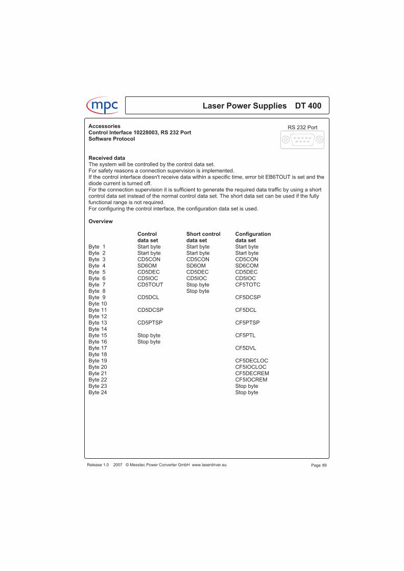
Received dataThe system will be controlled by the control data set.For safety reasons a connection supervision is implemented.If the control interface doesn't receive data within a specific time, error bit EB6TOUT is set and thediode current is turned off.For the connection supervision it is sufficient to generate the required data traffic by using a shortcontrol data set instead of the normal control data set. The short data set can be used if the fullyfunctional range is not required.For configuring the control interface, the configuration data set is used.
Overview
Control Short control Configurationdata set data set data set
Byte 1 Start byte Start byte Start byteByte 2 Start byte Start byte Start byteByte 3 CD5CON CD5CON CD5CONByte 4 SD6OM SD6OM SD6COMByte 5 CD5DEC CD5DEC CD5DECByte 6 CD5IOC CD5IOC CD5IOCByte 7 CD5TOUT Stop byte CF5TOTCByte 8 Stop byteByte 9 CD5DCL CF5DCSPByte 10Byte 11 CD5DCSP CF5DCLByte 12Byte 13 CD5PTSP CF5PTSPByte 14Byte 15 Stop byte CF5PTLByte 16 Stop byteByte 17 CF5DVLByte 18Byte 19 CF5DECLOCByte 20 CF5IOCLOCByte 21 CF5DECREMByte 22 CF5IOCREMByte 23 Stop byteByte 24 Stop byte
Page 89Release 1.0 2007 © Messtec Power Converter GmbH www.laserdriver.eu
Laser Power Supplies DT 400m c
RS 232 PortAccessoriesControl Interface 10228003, RS 232 PortSoftware Protocol
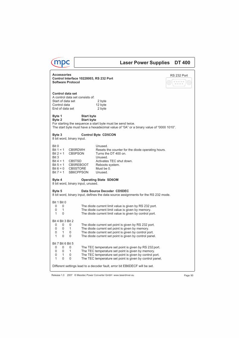
Control data setA control data set consists of:Start of data set 2 byteControl data 12 byteEnd of data set 2 byte
Byte 1 Start byteByte 2 Start byteFor starting the sequence a start byte must be send twice.The start byte must have a hexadecimal value of “0A” or a binary value of “0000 1010”.
Byte 3 Control Byte CD5CON8 bit word, binary input.
Bit 0 Unused.Bit 1 = 1 CB5RDWH Resets the counter for the diode operating hours.Bit 2 = 1 CB5PSON Turns the DT 400 on.Bit 3 Unused.Bit 4 = 1 CB5TSD Activates TEC shut down.Bit 5 = 1 CB5REBOOT Reboots system.Bit 6 = 0 CB5STORE Must be 0.Bit 7 = 1 SB6CPPSON Unused.
Byte 4 Operating State SD6OM8 bit word, binary input, unused.
Byte 5 Data Source Decoder CD5DEC8 bit word, binary input, defines the data source assignments for the RS 232 mode.
Bit 1 Bit 00 0 The diode current limit value is given by RS 232 port.0 1 The diode current limit value is given by memory.1 0 The diode current limit value is given by control port.
Bit 4 Bit 3 Bit 20 0 0 The diode current set point is given by RS 232 port.0 0 1 The diode current set point is given by memory.0 1 0 The diode current set point is given by control port.1 0 0 The diode current set point is given by control panel.
Bit 7 Bit 6 Bit 50 0 0 The TEC temperature set point is given by RS 232 port.0 0 1 The TEC temperature set point is given by memory.0 1 0 The TEC temperature set point is given by control port.1 0 0 The TEC temperature set point is given by control panel.
Different settings lead to a decoder fault, error bit EB6DECF will be set.
Laser Power Supplies DT 400
Page 90
m c
Release 1.0 2007 © Messtec Power Converter GmbH www.laserdriver.eu
RS 232 PortAccessoriesControl Interface 10228003, RS 232 PortSoftware Protocol
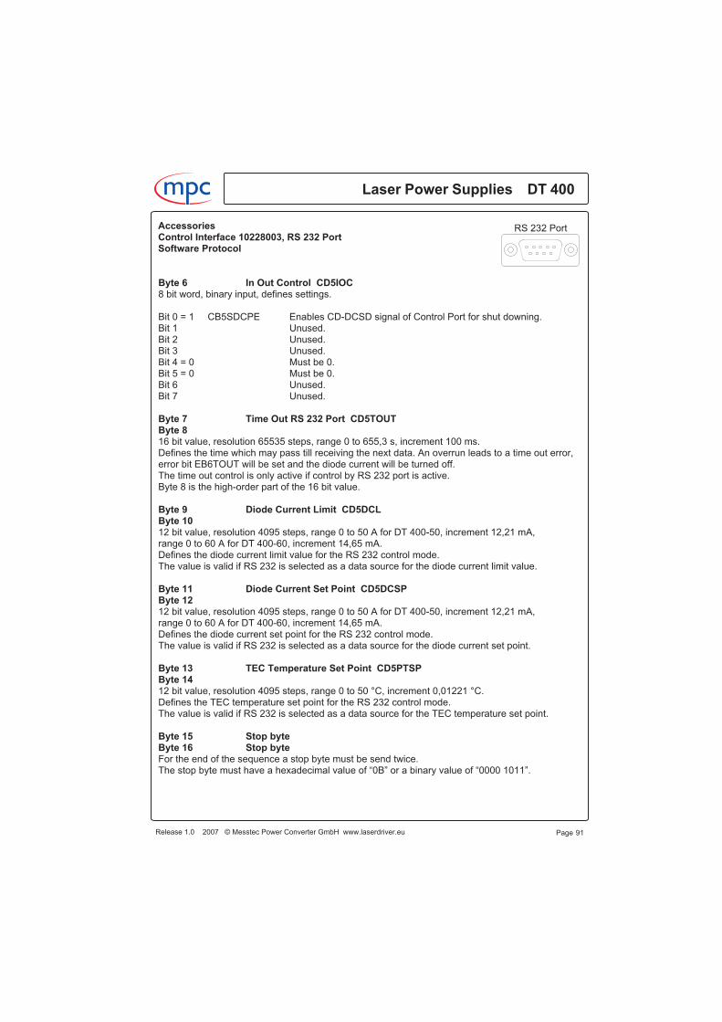
Byte 6 In Out Control CD5IOC8 bit word, binary input, defines settings.
Bit 0 = 1 CB5SDCPE Enables CD-DCSD signal of Control Port for shut downing.Bit 1 Unused.Bit 2 Unused.Bit 3 Unused.Bit 4 = 0 Must be 0.Bit 5 = 0 Must be 0.Bit 6 Unused.Bit 7 Unused.
Byte 7 Time Out RS 232 Port CD5TOUTByte 816 bit value, resolution 65535 steps, range 0 to 655,3 s, increment 100 ms.Defines the time which may pass till receiving the next data. An overrun leads to a time out error,error bit EB6TOUT will be set and the diode current will be turned off.The time out control is only active if control by RS 232 port is active.Byte 8 is the high-order part of the 16 bit value.
Byte 9 Diode Current Limit CD5DCLByte 1012 bit value, resolution 4095 steps, range 0 to 50 A for DT 400-50, increment 12,21 mA,range 0 to 60 A for DT 400-60, increment 14,65 mA.Defines the diode current limit value for the RS 232 control mode.The value is valid if RS 232 is selected as a data source for the diode current limit value.
Byte 11 Diode Current Set Point CD5DCSPByte 1212 bit value, resolution 4095 steps, range 0 to 50 A for DT 400-50, increment 12,21 mA,range 0 to 60 A for DT 400-60, increment 14,65 mA.Defines the diode current set point for the RS 232 control mode.The value is valid if RS 232 is selected as a data source for the diode current set point.
Byte 13 TEC Temperature Set Point CD5PTSPByte 1412 bit value, resolution 4095 steps, range 0 to 50 °C, increment 0,01221 °C.Defines the TEC temperature set point for the RS 232 control mode.The value is valid if RS 232 is selected as a data source for the TEC temperature set point.
Byte 15 Stop byteByte 16 Stop byteFor the end of the sequence a stop byte must be send twice.The stop byte must have a hexadecimal value of “0B” or a binary value of “0000 1011”.
Page 91Release 1.0 2007 © Messtec Power Converter GmbH www.laserdriver.eu
Laser Power Supplies DT 400m c
RS 232 PortAccessoriesControl Interface 10228003, RS 232 PortSoftware Protocol
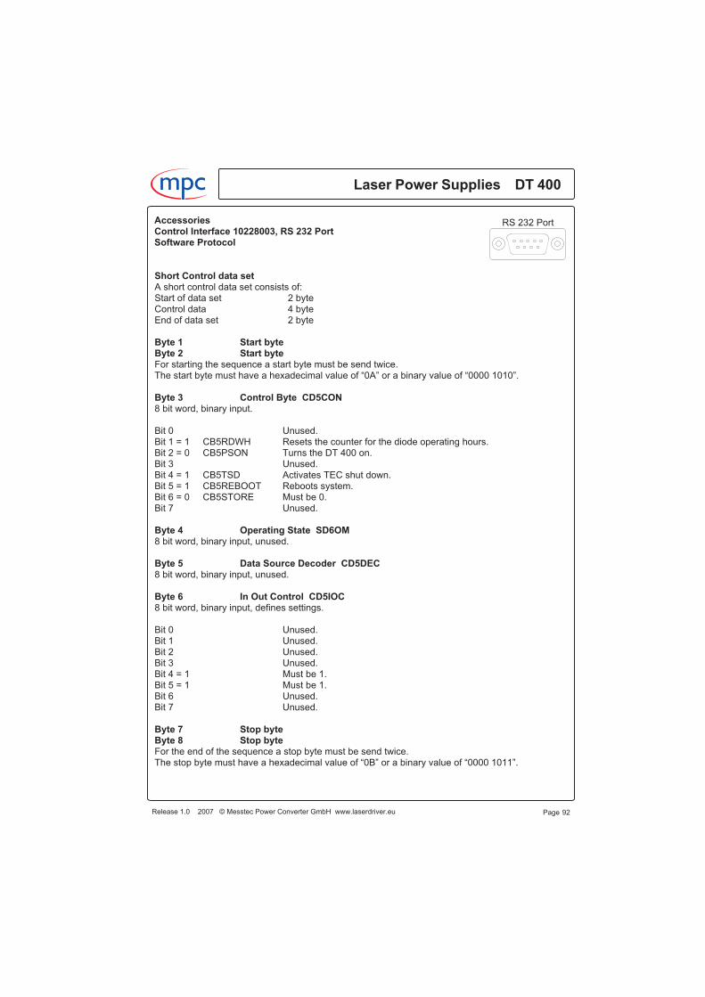
Short Control data setA short control data set consists of:Start of data set 2 byteControl data 4 byteEnd of data set 2 byte
Byte 1 Start byteByte 2 Start byteFor starting the sequence a start byte must be send twice.The start byte must have a hexadecimal value of “0A” or a binary value of “0000 1010”.
Byte 3 Control Byte CD5CON8 bit word, binary input.
Bit 0 Unused.Bit 1 = 1 CB5RDWH Resets the counter for the diode operating hours.Bit 2 = 0 CB5PSON Turns the DT 400 on.Bit 3 Unused.Bit 4 = 1 CB5TSD Activates TEC shut down.Bit 5 = 1 CB5REBOOT Reboots system.Bit 6 = 0 CB5STORE Must be 0.Bit 7 Unused.
Byte 4 Operating State SD6OM8 bit word, binary input, unused.
Byte 5 Data Source Decoder CD5DEC8 bit word, binary input, unused.
Byte 6 In Out Control CD5IOC8 bit word, binary input, defines settings.
Bit 0 Unused.Bit 1 Unused.Bit 2 Unused.Bit 3 Unused.Bit 4 = 1 Must be 1.Bit 5 = 1 Must be 1.Bit 6 Unused.Bit 7 Unused.
Byte 7 Stop byteByte 8 Stop byteFor the end of the sequence a stop byte must be send twice.The stop byte must have a hexadecimal value of “0B” or a binary value of “0000 1011”.
Laser Power Supplies DT 400
Page 92
m c
Release 1.0 2007 © Messtec Power Converter GmbH www.laserdriver.eu
RS 232 PortAccessoriesControl Interface 10228003, RS 232 PortSoftware Protocol
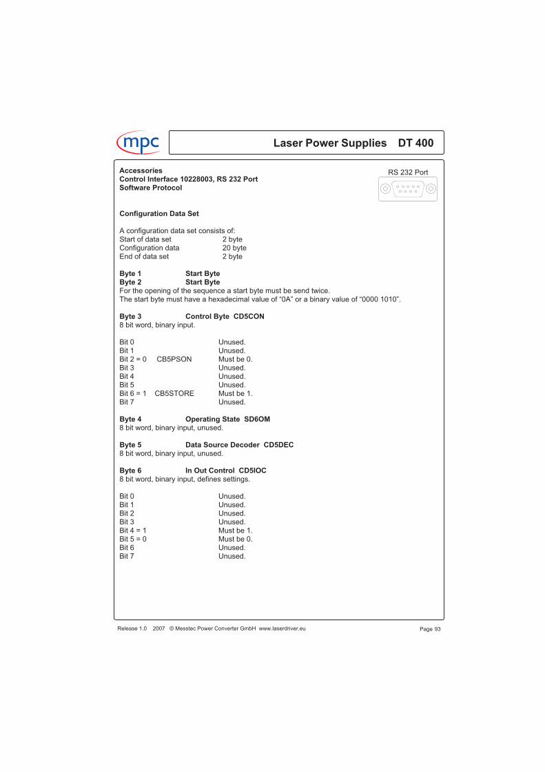
Configuration Data Set
A configuration data set consists of:Start of data set 2 byteConfiguration data 20 byteEnd of data set 2 byte
Byte 1 Start ByteByte 2 Start ByteFor the opening of the sequence a start byte must be send twice.The start byte must have a hexadecimal value of “0A” or a binary value of “0000 1010”.
Byte 3 Control Byte CD5CON8 bit word, binary input.
Bit 0 Unused.Bit 1 Unused.Bit 2 = 0 CB5PSON Must be 0.Bit 3 Unused.Bit 4 Unused.Bit 5 Unused.Bit 6 = 1 CB5STORE Must be 1.Bit 7 Unused.
Byte 4 Operating State SD6OM8 bit word, binary input, unused.
Byte 5 Data Source Decoder CD5DEC8 bit word, binary input, unused.
Byte 6 In Out Control CD5IOC8 bit word, binary input, defines settings.
Bit 0 Unused.Bit 1 Unused.Bit 2 Unused.Bit 3 Unused.Bit 4 = 1 Must be 1.Bit 5 = 0 Must be 0.Bit 6 Unused.Bit 7 Unused.
Page 93Release 1.0 2007 © Messtec Power Converter GmbH www.laserdriver.eu
Laser Power Supplies DT 400m c
RS 232 PortAccessoriesControl Interface 10228003, RS 232 PortSoftware Protocol
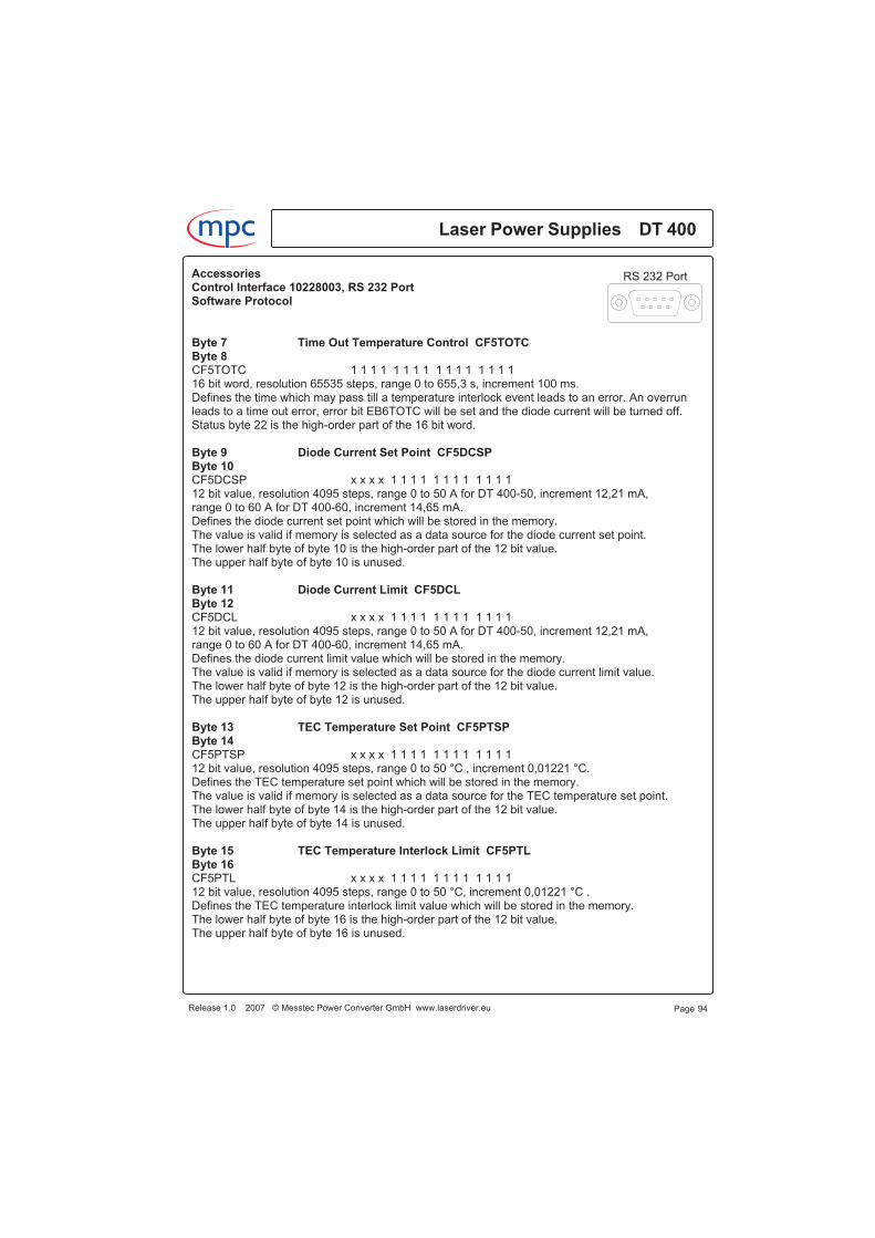
Byte 7 Time Out Temperature Control CF5TOTCByte 8CF5TOTC 1 1 1 1 1 1 1 1 1 1 1 1 1 1 1 116 bit word, resolution 65535 steps, range 0 to 655,3 s, increment 100 ms.Defines the time which may pass till a temperature interlock event leads to an error. An overrunleads to a time out error, error bit EB6TOTC will be set and the diode current will be turned off.Status byte 22 is the high-order part of the 16 bit word.
Byte 9 Diode Current Set Point CF5DCSPByte 10CF5DCSP x x x x 1 1 1 1 1 1 1 1 1 1 1 112 bit value, resolution 4095 steps, range 0 to 50 A for DT 400-50, increment 12,21 mA,range 0 to 60 A for DT 400-60, increment 14,65 mA.Defines the diode current set point which will be stored in the memory.The value is valid if memory is selected as a data source for the diode current set point.The lower half byte of byte 10 is the high-order part of the 12 bit value.The upper half byte of byte 10 is unused.
Byte 11 Diode Current Limit CF5DCLByte 12CF5DCL x x x x 1 1 1 1 1 1 1 1 1 1 1 112 bit value, resolution 4095 steps, range 0 to 50 A for DT 400-50, increment 12,21 mA,range 0 to 60 A for DT 400-60, increment 14,65 mA.Defines the diode current limit value which will be stored in the memory.The value is valid if memory is selected as a data source for the diode current limit value.The lower half byte of byte 12 is the high-order part of the 12 bit value.The upper half byte of byte 12 is unused.
Byte 13 TEC Temperature Set Point CF5PTSPByte 14CF5PTSP x x x x 1 1 1 1 1 1 1 1 1 1 1 112 bit value, resolution 4095 steps, range 0 to 50 °C , increment 0,01221 °C.Defines the TEC temperature set point which will be stored in the memory.The value is valid if memory is selected as a data source for the TEC temperature set point.The lower half byte of byte 14 is the high-order part of the 12 bit value.The upper half byte of byte 14 is unused.
Byte 15 TEC Temperature Interlock Limit CF5PTLByte 16CF5PTL x x x x 1 1 1 1 1 1 1 1 1 1 1 112 bit value, resolution 4095 steps, range 0 to 50 °C, increment 0,01221 °C .Defines the TEC temperature interlock limit value which will be stored in the memory.The lower half byte of byte 16 is the high-order part of the 12 bit value.The upper half byte of byte 16 is unused.
Laser Power Supplies DT 400
Page 94
m c
Release 1.0 2007 © Messtec Power Converter GmbH www.laserdriver.eu
RS 232 PortAccessoriesControl Interface 10228003, RS 232 PortSoftware Protocol
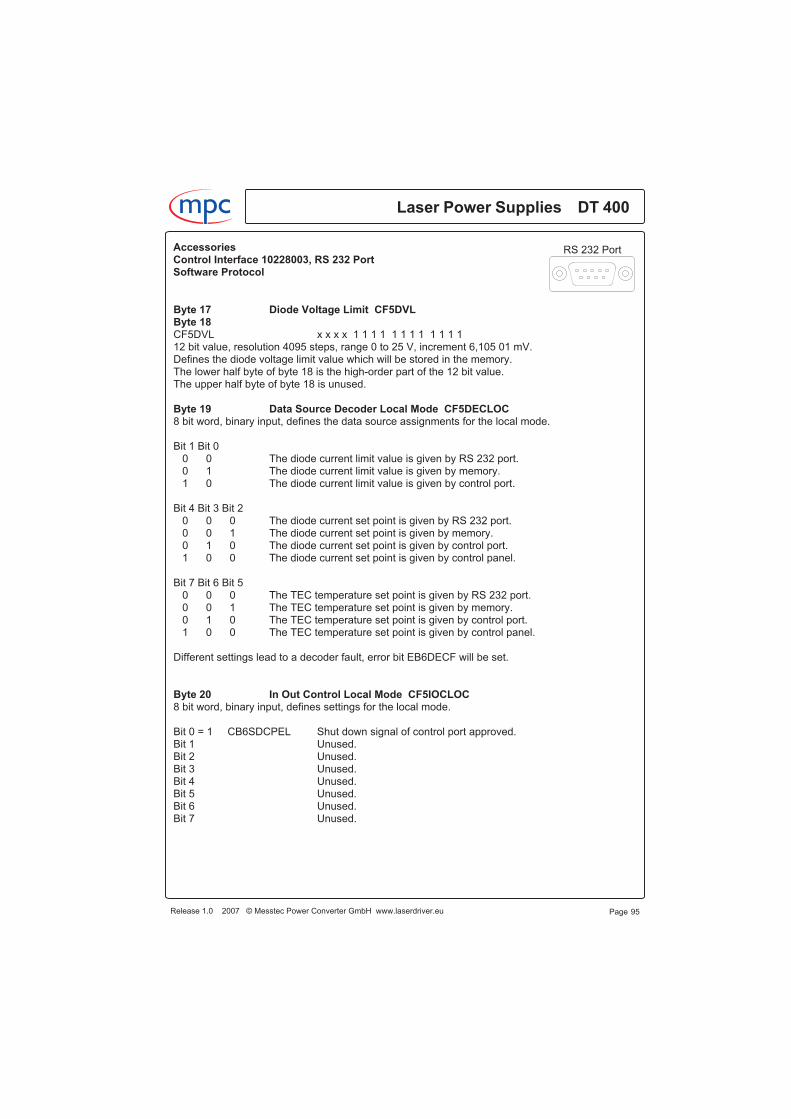
Byte 17 Diode Voltage Limit CF5DVLByte 18CF5DVL x x x x 1 1 1 1 1 1 1 1 1 1 1 112 bit value, resolution 4095 steps, range 0 to 25 V, increment 6,105 01 mV.Defines the diode voltage limit value which will be stored in the memory.The lower half byte of byte 18 is the high-order part of the 12 bit value.The upper half byte of byte 18 is unused.
Byte 19 Data Source Decoder Local Mode CF5DECLOC8 bit word, binary input, defines the data source assignments for the local mode.
Bit 1 Bit 00 0 The diode current limit value is given by RS 232 port.0 1 The diode current limit value is given by memory.1 0 The diode current limit value is given by control port.
Bit 4 Bit 3 Bit 20 0 0 The diode current set point is given by RS 232 port.0 0 1 The diode current set point is given by memory.0 1 0 The diode current set point is given by control port.1 0 0 The diode current set point is given by control panel.
Bit 7 Bit 6 Bit 50 0 0 The TEC temperature set point is given by RS 232 port.0 0 1 The TEC temperature set point is given by memory.0 1 0 The TEC temperature set point is given by control port.1 0 0 The TEC temperature set point is given by control panel.
Different settings lead to a decoder fault, error bit EB6DECF will be set.
Byte 20 In Out Control Local Mode CF5IOCLOC8 bit word, binary input, defines settings for the local mode.
Bit 0 = 1 CB6SDCPEL Shut down signal of control port approved.Bit 1 Unused.Bit 2 Unused.Bit 3 Unused.Bit 4 Unused.Bit 5 Unused.Bit 6 Unused.Bit 7 Unused.
Page 95Release 1.0 2007 © Messtec Power Converter GmbH www.laserdriver.eu
Laser Power Supplies DT 400m c
RS 232 PortAccessoriesControl Interface 10228003, RS 232 PortSoftware Protocol
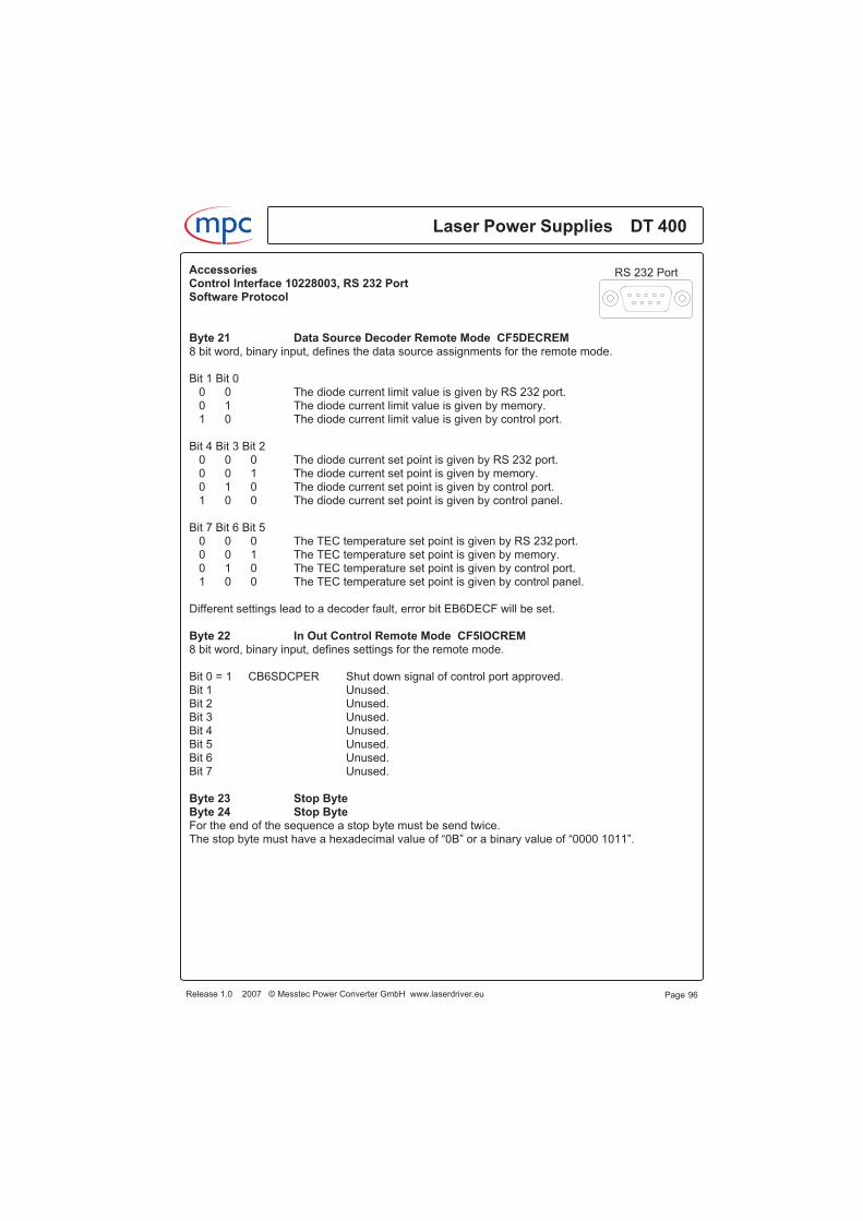
Byte 21 Data Source Decoder Remote Mode CF5DECREM8 bit word, binary input, defines the data source assignments for the remote mode.
Bit 1 Bit 00 0 The diode current limit value is given by RS 232 port.0 1 The diode current limit value is given by memory.1 0 The diode current limit value is given by control port.
Bit 4 Bit 3 Bit 20 0 0 The diode current set point is given by RS 232 port.0 0 1 The diode current set point is given by memory.0 1 0 The diode current set point is given by control port.1 0 0 The diode current set point is given by control panel.
Bit 7 Bit 6 Bit 50 0 0 The TEC temperature set point is given by RS 232 port.0 0 1 The TEC temperature set point is given by memory.0 1 0 The TEC temperature set point is given by control port.1 0 0 The TEC temperature set point is given by control panel.
Different settings lead to a decoder fault, error bit EB6DECF will be set.
Byte 22 In Out Control Remote Mode CF5IOCREM8 bit word, binary input, defines settings for the remote mode.
Bit 0 = 1 CB6SDCPER Shut down signal of control port approved.Bit 1 Unused.Bit 2 Unused.Bit 3 Unused.Bit 4 Unused.Bit 5 Unused.Bit 6 Unused.Bit 7 Unused.
Byte 23 Stop ByteByte 24 Stop ByteFor the end of the sequence a stop byte must be send twice.The stop byte must have a hexadecimal value of “0B” or a binary value of “0000 1011”.
Laser Power Supplies DT 400
Page 96
m c
Release 1.0 2007 © Messtec Power Converter GmbH www.laserdriver.eu
RS 232 PortAccessoriesControl Interface 10228003, RS 232 PortSoftware Protocol
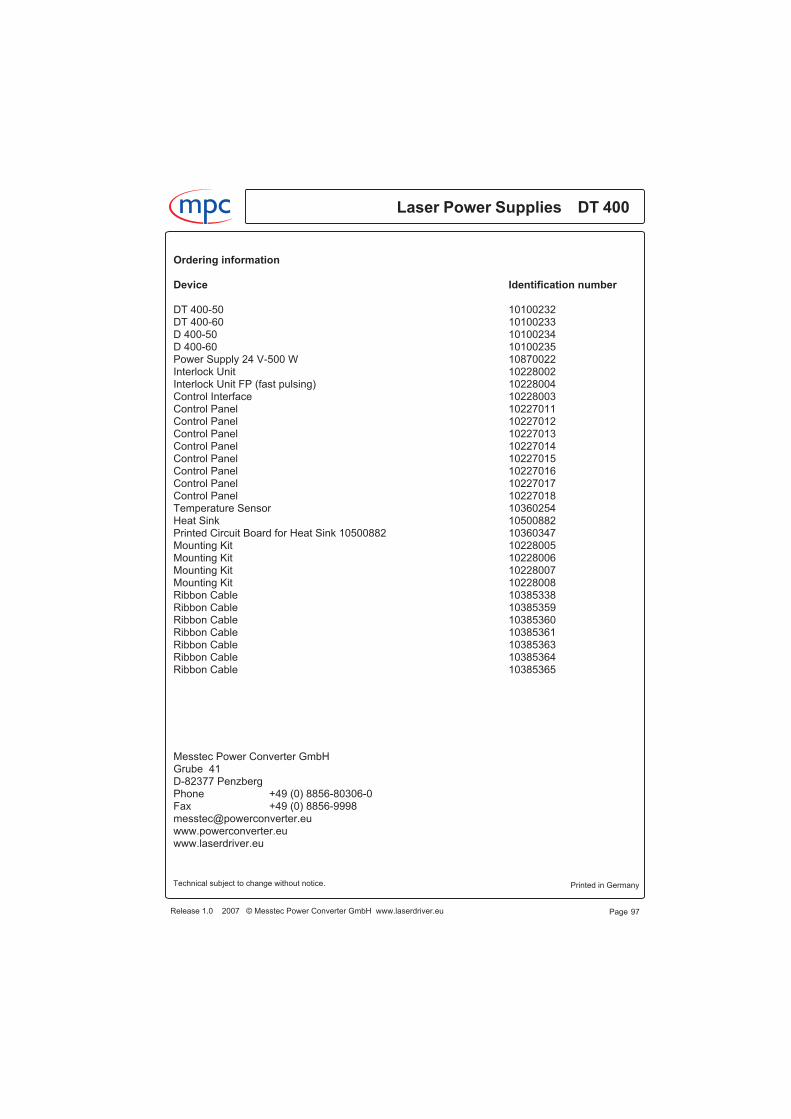
Ordering information
Device Identification number
DT 400-50 10100232DT 400-60 10100233D 400-50 10100234D 400-60 10100235Power Supply 24 V-500 W 10870022Interlock Unit 10228002Interlock Unit FP (fast pulsing) 10228004Control Interface 10228003Control Panel 10227011Control Panel 10227012Control Panel 10227013Control Panel 10227014Control Panel 10227015Control Panel 10227016Control Panel 10227017Control Panel 10227018Temperature Sensor 10360254Heat Sink 10500882Printed Circuit Board for Heat Sink 10500882 10360347Mounting Kit 10228005Mounting Kit 10228006Mounting Kit 10228007Mounting Kit 10228008Ribbon Cable 10385338Ribbon Cable 10385359Ribbon Cable 10385360Ribbon Cable 10385361Ribbon Cable 10385363Ribbon Cable 10385364Ribbon Cable 10385365
Messtec Power Converter GmbHGrube 41D-82377 PenzbergPhone +49 (0) 8856-80306-0Fax +49 (0) 8856-9998messtec@powerconverter.euwww.powerconverter.euwww.laserdriver.eu
Page 97Release 1.0 2007 © Messtec Power Converter GmbH www.laserdriver.eu
Laser Power Supplies DT 400m c
Printed in GermanyTechnical subject to change without notice.