Embed Size (px)
Citation preview

LM80Laser level transmitter
Operation Instruction OI/LM80-EN Rev. F
IntroductionThe LM80 is a high performance laser level transmitter that can accurately measure level, distance and position over long ranges in extreme environments. The LM80 features advanced timing and sophisticated signal processing for pinpoint accuracy at up to 100 m/328 ft (level applications) and to 150 m (492 ft) (positioning applications).
Features: – Range up 100 m (328 ft) (level applications) and up to 150
m (492 ft) (positioning applications) – No beam divergence = No false echoes – Measures any surface at any angle – Rugged and robust aluminum enclosure – Built-in purge port (1/8” NPT) – No calibration required – Easy and intuitive setup
Options and accessories: – Stainless steel dust tubes and cooling tubes – Stainless steel 4 and 6 inch universal mounting plates
sized for ANSI 150 and DIN PN10 flanges – Stainless steel raised face ANSI and DIN Flanges – 4” Triclover fittings – Handheld configuration device (LCD2) – Batery pack (BPK)
Measurement made easy
Intermediate rangeLevel products

2 OI/LM80-EN Rev. F | Operating Instruction
1.0 About this manual ................................................... 41.1 Purpose of document ......................................41.2 Definition of icons ............................................4
2.0 Safety summary ...................................................... 52.1 Warnings, cautions and notices ........................52.2 Laser warnings ................................................52.3 Electrical warnings ...........................................52.4 General warnings .............................................52.5 Conformity declaration and certificates ............52.6 Environmental information ................................62.7 Lasers and laser safety ....................................6
2.7.1 Lasers ................................................. 62.7.2 Laser safety ........................................ 6
2.8 Labels .............................................................6
3.0 Introduction ............................................................ 83.1 Overview .........................................................83.2 LM80 laser level transmitter key features...........93.3 Laser pointer .................................................11
4.0 Installation ............................................................ 114.1 General information .......................................114.2 Unpacking .....................................................114.3 Handling .......................................................114.4 Dusty conditions ............................................124.5 Alignment ......................................................124.6 Environmental ................................................124.7 ESD (electro static discharge) surge ...............124.8 Grounding .....................................................124.9 Electrical connections ....................................134.10 Operation indicator ......................................134.11 Cables, wiring and routing ............................144.12 Cable glands ...............................................144.13 Mounting .....................................................144.14 Quick start guide .........................................20
4.14.1 Setup procedure .............................. 204.14.2 Diagnostic checks ........................... 20
5.0 Maintenance and service ....................................... 205.1 Maintenance ..................................................205.2 Cleaning of optical lens ..................................215.3 Service ..........................................................215.4 Repacking .....................................................21
6.0 Communication .................................................... 216.1 Hardware ......................................................216.2 Available user settings ...................................226.3 Set points .....................................................226.4 Test functions ................................................22
6.5 Instrument settings ........................................226.6 Setting up a PC or laptop to communicate with the LM80 level transmitter .......................226.7 Setting up PuTTY ..........................................22
7.0 Menus and program options .................................. 237.1 Menu structure for PC or laptop .....................237.2 Programming menu flow chart ........................247.3 The main user menu ......................................247.4 The 4-20 mA settings menu ...........................257.5 The relay settings menu .................................267.6 The Instrument settings menu ........................267.7 Application settings and application table .......277.8 Laser application / setup table .......................287.9 The laser configuration device LCD2 ...............29
7.9.1 Changing numeric values ................... 297.9.2 Activating a test function .................... 297.9.3 Selecting from a list of options ........... 29
7.10 Troubleshooting ...........................................31
Appendix A Accessories ............................................. 32A.1 Accessories ..................................................32A.2 Dust tubes (P801)..........................................33A.3 Cooling tubes (P802) .....................................33A.4 LCD2 configuration device .............................33
Appendix B Extended software settings ....................... 34B.1 Extended menu .............................................34B.2 Passwords for advanced settings ...................34B.3 Agent Settings menu description and operation 35B.4 Program 0: standard parameters description: .35
B.4.1 Factory settings menu description and operation .................................... 36B.4.2 Hardware settings ............................. 37B.4.3 Special settings ................................. 38
B.5 Summary ......................................................38
Appendix C Certifications ............................................ 39C.1 CE Certificate ................................................39C.2 CSA Certificate .............................................40C.3 FM Certificate ...............................................44
Table of contents

Operating Instruction | OI/LM80-EN Rev. F 3
The Company
We are an established world force in the design and manufacture of measurement products for industrial process control, flow measurement, gas and liquid analysis and environmental applications. As a part of ABB, a world leader in process automation technology, we offer customers application expertise, service and sup-port worldwide.We are committed to teamwork, high quality manufacturing, advanced technology and unrivalled service and support.The quality, accuracy and performance of the Company’s products result from over 100 years experience, combined with ac-ontinuous program of innovative design and development to incorporate the latest technology.

4 OI/LM80-EN Rev. F | Operating Instruction
1.0 About this manual
1.1 Purpose of documentThis document is intended for personnel using the LM80 Level Transmitter for routine analysis and contains installation, user and troubleshooting instructions.
Read this manual carefully before working with the product. For personal and system safety and for optimum performance, make sure you thoroughly understand the contents before in-stalling, using or maintaining this instrument.
All servicing of the equipment is to be performed at factory by Qualified Service Personnel only.
No user/operator adjustments inside the LM80 level Transmitter are necessary or recommended by the manufacturer.
1.2 Definition of iconsThis publication includes Warning, Caution, and Information where appropriate to point out safety-related or other impor-tant information. It also includes Tip to point out useful hints to the reader. The corresponding symbols should be interpreted as follows:
The laser warning icon indicates the presence of a hazard related to the presence of a laser.
The electrical warning icon indicates the pres-ence of a hazard which could result in electrical shock.
The ISO General Warning icon indicates safety information that must be followed by user. The information concerns the presence of a hazard which will, could or may result in personal injury or even death.
The information icon alerts the reader to perti-nent facts and conditions in the use of the equip-ment.
The tip icon indicates advice on, for example, how to design your project or how to use a cer-tain function.
The ESD icon indicates the presence of equip-ment sensitive to electrostatic discharge.

Operating Instruction | OI/LM80-EN Rev. F 5
2.0 Safety summary
2.1 Warnings, cautions and noticesUser must comply with all warnings, cautions and notices indicated in this manual. Failure to comply with any of the warnings, cautions or notices can result in personal injuries and/or equipment damages. If you do not fully understand the information contained in this manual, please contact ABB. Refer to the back cover of this manual for contact information.
2.2 Laser warningsThe LM80 laser level transmitter uses a class 1M laser during normal operation. However, at installation and after a restart a pointing laser is activated for 2 minutes to allow positioning of the LM80 Level Transmitter. During these 2 minutes the LM80 Level Transmitter is a class 3R laser product. It is possible to configure the LM80 to completely turn off the laser pointer. When this is done the LM80 will be a class 1M device all the time. (see section B.4.3 special settings)
During standard operation:
Class 1M laser (905nm) is safe for all condi-tions of use except when passed through magnifying optics such as microscopes and telescopes. Do not view directly with optical instruments (binoculars or telescopes).
In the first 2 minutes after start-up:
Class 3R laser radiations (635 nm, 2 mW out-put power) are present at the bottom side of the instrument, i.e. originate from the pointing laser. Do not look in the laser beam.
Use of controls or adjustment of performance or procedures other thanthose specified herein may result in hazardous laser radiation exposure.
2.3 Electrical warnings
Ensure that the equipment and any devices or power cords connected to the LM80 Level Transmitter are properly grounded.
Protective earthing connection (grounding) must be active at all times. The absence of grounding can lead to a potential shock haz-ard that could result in serious personnel in-jury. If an interruption of the protective earthing connection is suspected, ensure the equip-ment is not used.Use the LM80 Level Transmitter ONLY if a properly grounded power outlet is available.Before using the level Transmitter, make sure the appropriate line voltage is available.Use a power extension ONLY if it has proper conductive protection (grounding).
If you observe noise on the level measurement through the 4-20 mA output this can be a sign of poor or intermittent grounding.
2.4 General warnings
No connection shall be made to the D connec-tor (RS232) inside the hazardous area.
Under certain extreme circumstances, exposed plastic (including powder coating) and un-earthed metal parts of the enclosure may store an ignition-capable level of electrostatic charge. Therefore, the user/installer shall implement precautions to prevent the build up of electro-static charge, e.g. locate the equipment where a charge-generating mechanism (such as wind-blown dust) is unlikely to be present and clean with a damp cloth.
Do not, under any circumstances, remove the warning and caution labels. Information must be available at all times for the security of the user.
Before measuring the level of flammable pro-ducts, equipment MUST be approved by local inspection authorities.
Read this manual thoroughly before using this equipment. If you do not understand the con-tent of this manual, contact ABB service per-sonnel.Prior to using the level Transmitter, Material Safety Data Sheets (MSDS) of all products be-ing monitored to be analyzed must be available at all times for the security of the user.
Do not use the equipment if any signs of dam-age are present. Contact ABB service person-nel.
2.5 Conformity declaration and certificates ABB LM80 Level Transmitters have the following conformity certifications: – CE – ATEX – IECEx – CSA – FM
Refer to SM/LM80-EN Safety Specifications for ATEX.

6 OI/LM80-EN Rev. F | Operating Instruction
2.6 Environmental informationThe LM80 Level Transmitter has required the extraction and use of natural resources for its production. Therefore, the LM80 Level Transmitter may contain hazardous substances that could impact health and environment. In order to avoid dissemination of these hazardous products into the environ-ment and also to reduce the extraction and protect our natural resources, ABB inc. strongly recommends to use appropriate recycling systems in order to make sure materials used to pro-duce your equipment are reused or recycled in a sound way. For European countries, at the end of life of the analyzer, con-tact your distributor before disposing of your equipment. The LM80 laser level transmitter is not subject to the European WEEE directive based on the exemption for fixed industrial in-stallations however most of it's components are easily recycla-ble. The LM80 falls into this category by virtue of the fact that it is meant to be permanently installed by a qualified installer on industrial vessels in locations like petrochemical complex-es, ore processing sites and food processing sites in order to measure the level of the content. The LM80 is not meant to be moved from site to site and serves no useful stand-alone purpose.
2.7 Lasers and laser safety
2.7.1 LasersLM80 Level Transmitter uses the following:Infrared Laser [class 1M]: Infrared beam (905 nm) used to mea-sure distance Laser Pointer [class 3R]: Visible beam (wavelength 635 nm) for servicing, targeting and aiming purpose.
2.7.2 Laser safetyLM80 is designated as a Class 1M laser device during all pro-cedures of operation as it comes with pointer for servicing and targeting use only. As per IEC60825-1, Ed 1.2, 2001-08, the following safety rules apply as stated on the LM80 warning labels.
According to IEC 60825-1, Ed 1.2, 2001-08, this product is designated as class 3R laser device in the first 2 minutes after startup.For Class 1M Laser Products: LASER RADIATION DO NOT VIEW DIRECTLY WITH OPTICAL INSTRUMENTS (BINOCU-LARS OR TELESCOPES)For Class 3R Laser Products: LASER RADIATION AVOID DI-RECT EYE EXPOSURE)
Infrared Laser, class 1M (standard operation) Visible Laser, class 3R (Laser Pointer first 2 min after start-up)
Wavelength 905 nm Wavelength 635 nm
Peak Power 45 w Power < 2mw CW
Average Power 12 mW Diameter 5 mm
Pulse Duration 20 ns Divergence < 1.5m rod
Pulse Rep Frequency 25 khz
Pulse Energy 50 nJ
Beam Diameter 20 mm
Divergence Δ < 0.3°
2.8 Labels
Figure 2- 1. LM80, Class 1M Laser Safety Label

Operating Instruction | OI/LM80-EN Rev. F 7
Figure 2- 2. Unit Label
Figure 2- 3. Manufacturer Label
Figure 2- 4. Label Location

8 OI/LM80-EN Rev. F | Operating Instruction
3.0 Introduction
3.1 OverviewThe LM80 laser level transmitter is a laser-based distance measuring instrument used in process control systems. The on-board microprocessor calculates distance by multiplying the speed of light by the time it takes for a laser pulse to travel from the instrument to a target and back.
The measuring laser uses invisible, infrared light. There is a second, visible aiming laser to help with the alignment of the mea-suring laser. The laser beams have very little divergence so that accurate targeting is easy even in silos or vessels that have internal structures.
A Easy measurement in silos with internal structure
B Easy measurement in silos with build-up.
C Level silos and bins: ideal for plastic pellets, grain, coffee, dry bulk solids, opaque liquids and powders
D Accurate, fast and long range positioning or anti-collision of moving ma-chinery.

Operating Instruction | OI/LM80-EN Rev. F 9
3.2 LM80 laser level transmitter key features – Narrow beam for direct targeting – Visible aiming laser – Long distance measuring capability – Dust and gas ignition proof housing – Measurements are not affected by the angle or roughness of the surface
being measured – Rapid response to moving levels and positions – Immunity to nearby objects – Immunity to vessel shape – Immunity to the material of construction of the vessel – Ability to reject momentary obstacles – User selectable program options – Below are mechanical dimensions:
M5 Earth screw assembly
½ inch NPT fitting for cable gland or conduit connection
½ inch NPTcable glandpart GCK
Imperial ½ inch NPTto M20 metric adapterpart GC1
Optical aperture 75 mm (3 in)
172
mm
(6.7
7 in
)
52 m
m (2
in)
M5 Earth screw assembly
) ni 15. 5( m
m 041
120
mm (4.7
2 in)
4 mounting holes 8.5 mm (0.33 in) diameter
Red laser pointer for aiming
Optical receiver 50 mm (1.97 in)
Measuring laser 25 mm (1 in) Tota
l opt
ical
ape
rtur
e 75
mm
(3 in
)
Dust tube purge outlet
Diameter at base 98.2 mm (3.9 in)
Diameter at base including posts 114 mm (4.5 in)
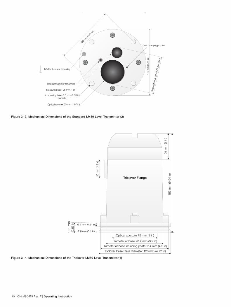
30 m
m (1
.2 in
)
Base Plate Diameter 140 mm (5.51 in)
166
mm
(6.5
4 in
)52
mm
(2 in
)
30 m
m (1
.2 in
)
9.5
mm
(0.3
7 in
)
Optical aperture 75 mm (3 in)
Diameter at base 98.2 mm (3.9 in)
Diameter at base including posts 114 mm (4.5 in)
Triclover Base Plate Diameter 120 mm (4.72 in)
6.1 mm (0.24 in)
2.6 mm (0.1 in)16.1
mm
(0.6
3 in
)
) ni 27. 4( m
m 021
112.
5 mm (4
.43
in)
Red laser pointer for aiming
Optical receiver50 mm (1.97 in)
Measuring laser 25 mm (1 in)
Tota
l opt
ical
ape
rtur
e 75
mm
(3 in
)
Seal groove
107.
5 mm (4
.23
in)
Standard Flange Triclover Flange
Figure 3- 1. LM80 Level Transmitter
Figure 3- 2. Mechanical Dimensions of the Standard LM80 Level Transmitter (1)
10 OI/LM80-EN Rev. F | Operating Instruction
M5 Earth screw assembly
½ inch NPT fitting for cable gland or conduit connection
½ inch NPTcable glandpart GCK
Imperial ½ inch NPTto M20 metric adapterpart GC1
Optical aperture 75 mm (3 in)
172
mm
(6.7
7 in
)
52 m
m (2
in)
M5 Earth screw assembly
) ni 15. 5( m
m 041
120
mm (4.7
2 in)
4 mounting holes 8.5 mm (0.33 in) diameter
Red laser pointer for aiming
Optical receiver 50 mm (1.97 in)
Measuring laser 25 mm (1 in) Tota
l opt
ical
ape
rtur
e 75
mm
(3 in
)
Dust tube purge outlet
Diameter at base 98.2 mm (3.9 in)
Diameter at base including posts 114 mm (4.5 in)
30 m
m (1
.2 in
)
Base Plate Diameter 140 mm (5.51 in)
166
mm
(6.5
4 in
)52
mm
(2 in
)
30 m
m (1
.2 in
)
9.5
mm
(0.3
7 in
)
Optical aperture 75 mm (3 in)
Diameter at base 98.2 mm (3.9 in)
Diameter at base including posts 114 mm (4.5 in)
Triclover Base Plate Diameter 120 mm (4.72 in)
6.1 mm (0.24 in)
2.6 mm (0.1 in)16.1
mm
(0.6
3 in
)
) ni 27. 4( m
m 021
112.
5 mm (4
.43
in)
Red laser pointer for aiming
Optical receiver50 mm (1.97 in)
Measuring laser 25 mm (1 in)
Tota
l opt
ical
ape
rtur
e 75
mm
(3 in
)
Seal groove
107.
5 mm (4
.23
in)
Standard Flange Triclover Flange
M5 Earth screw assembly
½ inch NPT fitting for cable gland or conduit connection
½ inch NPTcable glandpart GCK
Imperial ½ inch NPTto M20 metric adapterpart GC1
Optical aperture 75 mm (3 in)
172
mm
(6.7
7 in
)
52 m
m (2
in)
M5 Earth screw assembly
) ni 15. 5( m
m 041
120
mm (4.7
2 in)
4 mounting holes 8.5 mm (0.33 in) diameter
Red laser pointer for aiming
Optical receiver 50 mm (1.97 in)
Measuring laser 25 mm (1 in) Tota
l opt
ical
ape
rtur
e 75
mm
(3 in
)
Dust tube purge outlet
Diameter at base 98.2 mm (3.9 in)
Diameter at base including posts 114 mm (4.5 in)
30 m
m (1
.2 in
)
Base Plate Diameter 140 mm (5.51 in)
166
mm
(6.5
4 in
)52
mm
(2 in
)
30 m
m (1
.2 in
)
9.5
mm
(0.3
7 in
)
Optical aperture 75 mm (3 in)
Diameter at base 98.2 mm (3.9 in)
Diameter at base including posts 114 mm (4.5 in)
Triclover Base Plate Diameter 120 mm (4.72 in)
6.1 mm (0.24 in)
2.6 mm (0.1 in)16.1
mm
(0.6
3 in
)
) ni 27. 4( m
m 021
112.
5 mm (4
.43
in)
Red laser pointer for aiming
Optical receiver50 mm (1.97 in)
Measuring laser 25 mm (1 in)
Tota
l opt
ical
ape
rtur
e 75
mm
(3 in
)
Seal groove
107.
5 mm (4
.23
in)
Standard Flange Triclover Flange
Figure 3- 3. Mechanical Dimensions of the Standard LM80 Level Transmitter (2)
Figure 3- 4. Mechanical Dimensions of the Triclover LM80 Level Transmitter(1)

Operating Instruction | OI/LM80-EN Rev. F 11
M5 Earth screw assembly
½ inch NPT fitting for cable gland or conduit connection
½ inch NPTcable glandpart GCK
Imperial ½ inch NPTto M20 metric adapterpart GC1
Optical aperture 75 mm (3 in)
172
mm
(6.7
7 in
)
52 m
m (2
in)
M5 Earth screw assembly
) ni 15. 5( m
m 041
120
mm (4.7
2 in)
4 mounting holes 8.5 mm (0.33 in) diameter
Red laser pointer for aiming
Optical receiver 50 mm (1.97 in)
Measuring laser 25 mm (1 in) Tota
l opt
ical
ape
rtur
e 75
mm
(3 in
)
Dust tube purge outlet
Diameter at base 98.2 mm (3.9 in)
Diameter at base including posts 114 mm (4.5 in)
30 m
m (1
.2 in
)
Base Plate Diameter 140 mm (5.51 in)
166
mm
(6.5
4 in
)52
mm
(2 in
)
30 m
m (1
.2 in
)
9.5
mm
(0.3
7 in
)
Optical aperture 75 mm (3 in)
Diameter at base 98.2 mm (3.9 in)
Diameter at base including posts 114 mm (4.5 in)
Triclover Base Plate Diameter 120 mm (4.72 in)
6.1 mm (0.24 in)
2.6 mm (0.1 in)16.1
mm
(0.6
3 in
)
) ni 27. 4( m
m 021
112.
5 mm (4
.43
in)
Red laser pointer for aiming
Optical receiver50 mm (1.97 in)
Measuring laser 25 mm (1 in)
Tota
l opt
ical
ape
rtur
e 75
mm
(3 in
)
Seal groove
107.
5 mm (4
.23
in)
Standard Flange Triclover Flange
Figure 3- 5. Mechanical Dimensions of the Triclover LM80 Level Transmitter(2)
3.3 Laser pointerThe LM80 laser level transmitter comes standard with a laser pointer that is turned off during normal operation.
The pointer will come on by software control (by hitting SPACEBAR on a laptop computer keyboard or the EXIT but-ton on the LCD2 configuration device). When this is done the Main Menu appears, the instrument stops measuring and is accessible for activities such as aiming check and set-up. Upon measurement restart, the pointer will turn off and remain off during normal operation.
4.0 Installation
4.1 General informationThe LM80 laser level transmitter is an optical, line of sight device that is used for non-contact distance measurement. There must be no obstacles directly in the beam path.
The LM80 laser level transmitter measures in engineering units (feet or meters) so there is no need for calibration prior to installation. The instrument can simply be aimed directly to-wards an object and it will measure the real physical distance from its face. Any special settings required by the user may be loaded into the device inside the work area or workshop prior to mounting the LM80 laser level transmitter outside.
4.2 UnpackingThe product is supplied in a cardboard container with internal shock absorbing packaging. Keep this packaging material to always transport the instrument in the packaging supplied to reduce the chance of damage.
4.3 HandlingThe product is designed to withstand many industrial envi-ronmental conditions. However, a few handling precautions will ensure reliable operation of the unit for extended periods of time.
– DO NOT DROP THE INSTRUMENT – Remove dirt from the lens with air or if not sufficient, clean
with alcohol and optical wipes. – Do not install or connect with the power on. – Do not open the instrument compartment or expose the
internal electronics to water or dirt. – Ensure that the cable glands or conduits are tight after
connecting the external cable. – Ensure that the lid to the terminal compartment is tight
after connections have been made. – Do not point the instrument at the sun. – Do not open or modify the instrument. – Store in a cool dry place.

12 OI/LM80-EN Rev. F | Operating Instruction
4.4 Dusty conditionsIn dusty conditions, it is strongly recommended that a Dust Tube be installed (P801/Section Accessories on page 33).
The Dust Tube is a very simple and effective device, designed to prevent dust settling on the lens. The LM80 laser level transmitter can be used in most dust present applications by using the Dust Tube accessory. However, if the dust level is very high, then using the air purge (set to 3-5 psi) on the Dust Tube is recommended.
4.5 AlignmentThe LM80 laser level transmitter is simple to install and align. It has a narrow and direct beam so there is no interference from nearby objects.
The main consideration required when aligning the instrument is a clear line of sight.
The LM80 laser level transmitter will measure off a surface that is rough or is at an oblique angle to the beam. There is no need to align the instrument perpendicular to the material as it will not be affected by the cone up or down of the material. However, for liquid applications, mount the laser perpendicu-lar as far as possible to the surface.
4.6 EnvironmentalThe LM80 laser level transmitter should be installed in an area that is within the specified temperature range, taking into con-sideration the enclosure ratings and the materials of construc-tion. When installed, the LM80 laser level transmitter should be accessible for programming if necessary.
While the initial (cold start) accuracy of the LM80 laser level transmitter is likely to be within speci-fication, a settling period of approximately 15 minutes may be required to allow the electronic components to fully warm up and the internal temperature to stabilize.
4.7 ESD (electro static discharge) surgeThe LM80 laser level transmitter are manufactured to the highest quality standards and are designed to survive most industrial environments. These instruments use electronic components that may be damaged by static electricity pres-ent in most work environments. Make sure all equipment is connected to good earth ground. Make sure all electrical con-nections are properly tight and none of them are partial or floating.
4.8 GroundingIt is recommended to use a AWG 16 or 1.5 mm² wire for earth connection. For best results, ABB recommends using a size 10 earth lug with a copper body terminal per ASTM B-152, a tin plating per MIL-T-10727, and a manufacturer AMP port No. 34112 or No. 34109. The earth wire terminated with the recommended earth lug must be connected to the duly des-ignated grounding screw.
60 °C / 140 °F45 °C / 113 °F (with heated lenses)
- 40 °C / - 40 °F
Figure 4- 1. Operating Temperature Limits

Operating Instruction | OI/LM80-EN Rev. F 13
Figure 4-2. Terminal Compartment
4.10 Operation indicatorThe operation indicator is a LED mounted in the terminal compartment of the LM80 laser level transmitter, which shows the stage the laser unit is currently in. When flashing, the LED indicates that the laser unit is performing measurement. When the LED is continuously lit, the LED indicates that the laser unit is in the Main Menu mode, awaiting for set-up.
Figure 4- 3. Typical Connection
4.9 Electrical connections

14 OI/LM80-EN Rev. F | Operating Instruction
4.13 MountingThe LM80 laser level transmitter produces a narrow, straight laser beam. It should be mounted facing directly towards the area to be measured with no obstacles directly in the beam path. When aiming over a long range or to a reflective target the built-in aiming laser is a useful alignment tool. Ensure that the visible aiming laser is in the center of the target at all oper-ating distances.
The LM80 laser level transmitter has four mounting holes on the front flange. The instrument can be bolted directly onto a flange or bracket. In applications where dust may be present (even in very small quantities) it is recommended that a dust tube accessory be used.
The LM80 laser level transmitter may receive stronger signals in subdued lighting and dark con-ditions than it does in direct sunlight.
Exposure to some chemicals may degrade the lens or the sealing properties of the LM80 level Transmitter or degrade the lens.
Explosion hazard. Do not open or disconnect equipment when a flammable or combustible at-mosphere is present.
Always use thread sealant or conduit seal in order to maintain NEMA 4 rating.
Avoid mounting the instrument close to a stream of material that may fall in front of it. Avoid aim-ing the instrument down long narrow pipes that have rough inner walls. Ensure that the instrument never points directly at or near the sun. Check the operation over the full range of conditions to be measured after installing.
Once all connections are made, screw the lid by hand. To make sure the electrical compartment is not too easily accessible the compartment lid has to be firmly tightened. To do so, insert a 300 mm square bar in the slot in the top of the cover and tighten hand tight.
A circuit breaker or switch in the building installation, marked as the disconnect switch shall be in close proximity to the equipment and within easy reach of the OPERATOR.
4.11 Cables, wiring and routingAlways use shielded cables for power supply and signal. It is recommended to us an AWG16 or 1.5 mm² multi-core cable. The number of cores will depend upon the outputs required from the LM80 laser level transmitter. For a 4-20 mA interface, use a twisted pair shielded cable. Do not install a LM80 laser level transmitter or route the signal cables in close vicinity to high voltage electrical cables.
In an industrial environment with extreme pres-ence of EMI (electromagnetic interference), such as rock quarries, mines or large chemical plants, ABB recommends the use of noise filters on the +24 VDC power supply to the instrument and signal isolators on the 4/20 mA output.
Field wiring shall be rated for at least 65 °C/150 °F.
4.12 Cable glandsThe LM80 Level Transmitter has ½ inch NPT cable gland entry. A suitably certified ½ inch NPT cable gland being certified to either Ex e or Ex n and having an IP rating of at least IP64 shall be used. The cable glands supplied by ABB are ATEX and CE certified and meet the above requirements.
For metric cable glands or conduits, ABB offers an optional EXd/e flameproof imperial to metric (½ inch NPT to M20) adap-tor that is certified according to above standards.
These cable glands can only be used with braided shield ca-bles. When installing them, make sure to fold the cable shield over the O-ring which presses the braiding against the inside wall of the body, this ensures good contact.
For cable glands that are not supplied by ABB, please refer to your supplier’s data sheet for proper installation.
ABB does not assume any responsibility for non ATEX or CE certified cable glands or adaptor that do not meet the above requirements.
Figure 4- 4. Cable Gland
Operating Instruction | OI/LM80-EN Rev. F 15
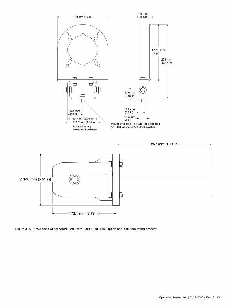
160 mm (6.3 in)38.1 mm (1.5 in)
177.8 mm (7 in)
233 mm (9.17 in)
27.6 mm (1.09 in)
12.7 mm (0.5 in)
25.4 mm (1 in)
47.6 mm (1.9 in)
95.3 mm (3.75 in)112.7 mm (4.44 in) Mount with 5/16-18 x .75’’ long hex bolt
5/16 flat washer & 5/16 lock washerApproximately including hardware
Figure 4- 5. Dimensions of Standard LM80 with P801 Dust Tube Option and A800 mounting bracket
257 mm (10.1 in)
Ø 140 mm (5.51 in)
172.1 mm (6.78 in)

16 OI/LM80-EN Rev. F | Operating Instruction
Figure 4- 6. LM80 laser level transmitter with P802 cooling tubes and HPSG
Figure 4- 7. Flange Mounting Assembly
SHCS M8x1.25 with flat and lock washers
G800 Gasket Kit (Dust tube gasket)
P801 dust tube
G800 Gasket Kit (Flange gasket)
Mounting flange(F804, F806, F810, F815)
SHSC M8x1.25 x 40 mm with flat and lock washers
G800 Gasket kit(Cooling tube gasket)
Cooling tubes
G800 Gasket kit(Flange gasket)
High pressure sight glass with spray ring and gaskets
Flange (F804, F806,F810, F815)

Operating Instruction | OI/LM80-EN Rev. F 17
SHCS M8X1.25 x 40mmwith flat and lock washers
P804/P806
G800 Gasket Kit (Dust tube gasket)
P801 Dust Tube
G800 Gasket Kit(Mounting plate gasket)
SHCS M8 x 1.25with flat and lock washers
A800 Adjustable mounting bracket
Dust Tube P801
4x M8 Hex Nut
G800 Gasket Kit(Dust Tube gasket)
G800 Gasket Kit (Mounting plate gasket)
Figure 4-8. Mounting Plate Assembly
Figure 4-9. P801 Dust Tube and A800 Adjustable Mounting Bracket assembly

18 OI/LM80-EN Rev. F | Operating Instruction
Figure 4-10. P801 Dust Tube and S800 Swivel Mounting Flange assembly
Figure 4-11. Suggested Mounting Arrangements for Solid Materials
G800 gasket kit (Dust tube gasket)
G800 gasket kit (Mounting plate gasket)
Swivel flange gasket
Dust tube P801)
Swivel flange (S800)
Operating Instruction | OI/LM80-EN Rev. F 19
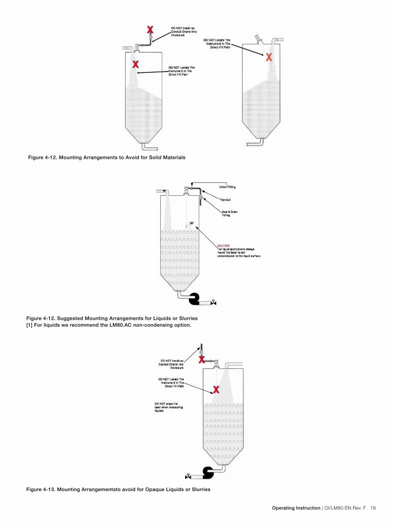
Figure 4-12. Mounting Arrangements to Avoid for Solid Materials
Figure 4-12. Suggested Mounting Arrangements for Liquids or Slurries[1] For liquids we recommend the LM80.AC non-condensing option.
Figure 4-13. Mounting Arrangementsto avoid for Opaque Liquids or Slurries

20 OI/LM80-EN Rev. F | Operating Instruction
4.14 Quick start guide
4.14.1 Setup procedure1. Connect up power and 4/20 mA wires to the LM80 laser
level transmitter2. For standard LM80 unit refer to 4.9 Electrical connections
on page 13. 3. Switch power ON.4. Establish communication with the LM80 unit. Refer to sec-
tion 6.0 Communication on page 21 depending on com-munication device used.
5. Set 4 mA and 20 mA set points. Refer to 7.4 The 4-20 mA settings menu on page 25.
6. Set Program (Program is Application Oriented Mode of Operation and it is set according to the application the unit is used for). Refer to 7.8 Laser application / setup table on page 28.
7. Set Fail Safe Mode. Refer to 7.4 The 4-20 mA settings menu on page 25, point 3.
8. In Main Menu start the instrument (if LCD2 is used for communication with LM80, simply press EXIT and instru-ment will start measurement).
4.14.2 Diagnostic checksAfter installation the LM80 laser level transmitter should be checked and tested for correct wiring connections and correct operation. The example below is for the LCD2 but the same checks can be made on the PC or Laptop using PuTTY.
– Turn the power off. – Remove the back lid from the LM80 laser level transmitter. – Connect the LCD2 configuration device to the program-
ming port. – Connect a multi-meter or loop tester between the OUT and
RETURN lines of the 4-20 mA loop. – Connect multimeter on indicators to the relays if these are
to be used. – Turn the power ON. – After a few seconds the LCD2 will begin to display a dis-
tance reading. – Press Exit. – Scroll to the 4-20 mA Test menu using the arrow up and
arrow down keys. – Press Enter to activate the test function. – Force the 4-20 mA to a test value using the arrow left and
arrow right keys. – Check that the reading on the 4-20 mA indicator matches
the test value displayed. If it does not, use the trim menu. If the problem cannot be corrected with the trim menu con-tact ABB after sales support (see back cover for contact information).
– Press Exit once the test is completed. – Scroll to the Relay A Test or Relay B Test menu using the
arrow up and arrow down keys. – Press Enter to activate the test function. – Force the relay to an ON or OFF state using the arrow left
and arrow right keys. – Check that the relay indicator matches the test condition
displayed, if it does not contact ABB after sales support (see back cover for contact information).
– Press Exit once the test is completed. – Press Exit once more to restart the measuring process. – Confirm that the LM80 laser level transmitter and its con-
nections are operating correctly by measuring a range of distances under all typical conditions.
– Turn the power off. – Remove the LCD2 communications cable and replace the
cover. – Turn the power on.
It is strongly recommended that correct opera-tion at extremes of distance or other abnormal operating conditions be tested to ensure that unexpected results are avoided.
5.0 Maintenance and service
5.1 MaintenanceThe LM80 laser level transmitter is an optical electronic device with no moving parts. For this reason, no regular maintenance is required. When installed in a dusty environment, the LM80 laser level transmitter must be equipped with dust tubes. This will ensure long-term reliability and performance. However, be-fore installing the LM80 laser level transmitter, it is recommend-ed the user performs a visual check on the lenses. If particles of dust are present on the lenses, use instrument air to blow them off (see 5.2 cleaning of optical lens).
Periodic inspection of the lenses is recommended. The higher the dust level or environmental exposure the more frequent these inspections should be.
LM80 laser level transmitter does not contain field replaceable parts and there is no sched-uled maintenance required to keep this product in compliance.
Always turn the power off before removing or in-specting the LM80 laser level transmitter. Do not open the LM80 laser level transmitter. All service or maintenance is to be performed at the factory by qualified ABB service personnel.

Operating Instruction | OI/LM80-EN Rev. F 21
5.2 Cleaning of optical lensThe optical lens is a sensitive component and must be cleaned with caution.
Clean the lens with instrument air or if not sufficient, clean with alcohol and optical wipes.
When cleaning with air, make sure it is instru-ment grade at ambient temperature and humi-dity.
Opening the LM80 laser level transmitter will void warranty.
5.3 ServiceThe LM80 laser level transmitter does not contain user service-able parts and there is no service allowed by the customer. Ser-vice is only to be handled by authorized FACTORY TRAINED PERSONNEL. Please contact ABB, refer to back cover for con-tact details.
If you are unable to solve a problem contact ABB. Before con-tacting ABB, please check the following: – All cables are properly installed. – The STATUS display on the electronic module is ON. – All pertinent Troubleshooting steps in this manual have
been followed.
Before sending a level Transmitter to ABB, you must first – Obtain a Contamination Data Sheet from ABB’s after sales
service. – Fill out and sign the Contamination Data Sheet. Do not
forget to check the check boxes of the Non-contaminated Material Declaration section. Then return the fully complet-ed Declaration to ABB.
– Obtain the authorization from ABB personnel. You must receive a Return Merchandise Authorization (RMA) prior to sending the analyzer back to ABB, otherwise receipt of analyzer will be refused.
5.4 RepackingTo prepare the level Transmitter for shipment, pack it in the shock absorbing packaging it was delivered in. Make sure to pack the LM80 Level Transmitter in its transportation box with the internal shock absorbing packaging.
6.0 Communication
6.1 HardwareCommunication with the LM80 laser level transmitter is done with an RS232 to USB cable (USBR). This cable is optional, i.e. is not delivered standard with the LM80, refer to Appendix A Accessories. A wide range of computers and other devices can be used to establish a communication channel using a standard terminal emulation program. Settings for this program are detailed in later sections.
6- 1. Possible Communication Methods
PC to LM80 USB to Serial con-verter �
Laptop to LM80 USB to Serial con-verter �
LCD2
�
The LCD2 includes an RS232 cable.

22 OI/LM80-EN Rev. F | Operating Instruction
LCD2 (Laser communication device) allows fast and easy com-munication with LM80 without the need to connect to a com-puter. The LCD2 connects directly to the LM80 and requires no special settings, it starts communicating as soon as it is connected to the LM80 and the LM80 is powered up.
6.2 Available user settingsThe LM80 laser level transmitter has a number of configuration settings that can be changed via the programming port located in the terminal compartment. The Laser Transmitter Configu-ration Device accessory [LCD2] or any personal computer or laptop with USB port facilities [PC, Laptop] may be used to change these settings. The LCD2 has access to a limited num-ber of settings options while a personal computer has full ac-cess to every available option.
A brief description of the available settings is provided below.
6.3 Set pointsThe set points are distances that represent the end points for the 4-20 mA output and switching points for the relays [LCD2, PC, Laptop].
A trim function is also available for the 4-20 mA output that adjusts the output current to match a calibration device [PC, Laptop].
6.4 Test functionsEach output can be driven to a known value using these func-tions. The field wiring and indication systems can be checked at the time of installation without having to physically measure a level or position [LCD2, PC, Laptop].
6.5 Instrument settingsThe LM80 laser level transmitter can be set to display units of feet or meters for the set points and the measurement screen [LCD2, PC, Laptop].
There is a facility to move the measuring datum face (zero point) from the flange (factory default) to some other point such as the end of the dust tube accessory [LCD2, PC, Laptop].
There are also five selectable program options that alter the performance of the instrument to suit the requirements of the application; you can choose from Standard, Light Dust, Heavy Dust, Positioning and Custom [LCD2, PC, Laptop].
6.6 Setting up a PC or laptop to communicate with the LM80 level transmitterProgramming (or setting) the LM80 laser level transmitter using the RS232 to USB cable (USBR) and a PC or Laptop computer requires a terminal emulation program. Many terminal emula-tion programs are available, ABB recommends using Putty on Windows® or Terminal on OS/X.
6.7 Setting up PuTTY1. Download PuTTY from the Internet.2. Double-click on Putty.exe.
Under Session, change the Connect Using Box to indicate which serial port (with USB cable COM5 is typical) will be used. The correct port can be found in the Windows Device manager. See Figure 6- 2.
Figure 6- 2 PuTTY Configuration Dialog Box

Operating Instruction | OI/LM80-EN Rev. F 23
3. Click the Connection Option and then Serial (left side) and insert the correct numbers as shown below and in Figure 6- 2. Click OK to close the Configure Box and OK to close the Properties Box.
Baud Rate: 19200Data Bits: 8Parity: NoneFlow Control: NoneStop Bits: 1
4. Click Open. PUTTY is now properly configured to run.
7.0 Menus and program options
7.1 Menu structure for PC or laptopAfter the terminal emulation software on the PC or Laptop has been correctly set up according to Setting up PuTTY, the communication cable should be connected to the instrument. Switch on power to the instrument and the instrument will start running.After displaying the software and firmware revisions the instrument goes through an initialization sequence. It will then print out distance and mA on a continuously scrolling screen.
Figure 6- 3. Configuration Dialog Box
Figure 7- 1. Normal Startup Screen
4-20 mA Readout
4-20 mA readout is the numerical presentation of the mA value on the 4-20 mA interface
for the corresponding distance.
Distance
The displayed numbers represent the distance from the LM80 front measure-
ment face (the flange surface) to the object at which the beam is pointed.
The distance is displayed in selectable units (feets or meters).

24 OI/LM80-EN Rev. F | Operating Instruction
7.2 Programming menu flow chart
Figure 7- 2. Menu Flow Chart
7.3 The main user menu
[S]tart-------------------------------------------
+ ---- ++ LM 80 ++ Number AA00191 Rev 2.20 ++ Main User Settings Menu +
+--------------------------------------++ ++ 1:4-20mA Settings ++ 2:Relay Settings ++ 3:Instrument Settings ++ ++ +
+++++++++++++++++++++++++++++++
Figure 7- 3. The Main User Menu
Sending a Space character to the LM80 laser level transmitter will stop the measuring operation and the instrument will enter the Main User Settings Menu. Sub-menus can be selected by pressing the numeric keys indicated adjacent to the name of each menu. Sending an “S” character restarts the measuring process. If no character is received for two minutes the instru-ment will auto-restart.
The Main Menu is the main starting point for the set-up, perfor-mance optimization, diagnostic and access of different features on the LM80 laser level transmitter. The Main Menu contains in its heading, important information such as:
Instrument Type - LM80: Laser ModelSerial Number - AA00191: Always use this number when re-questing an RMA from Service.Software Revision - Rev 2.20: This is the current software revi-sion loaded in the unit.
The LM80 laser level transmitter programming menus are de-signed to be intuitive, self-explanatory and easy to use.
Operating Instruction | OI/LM80-EN Rev. F 25
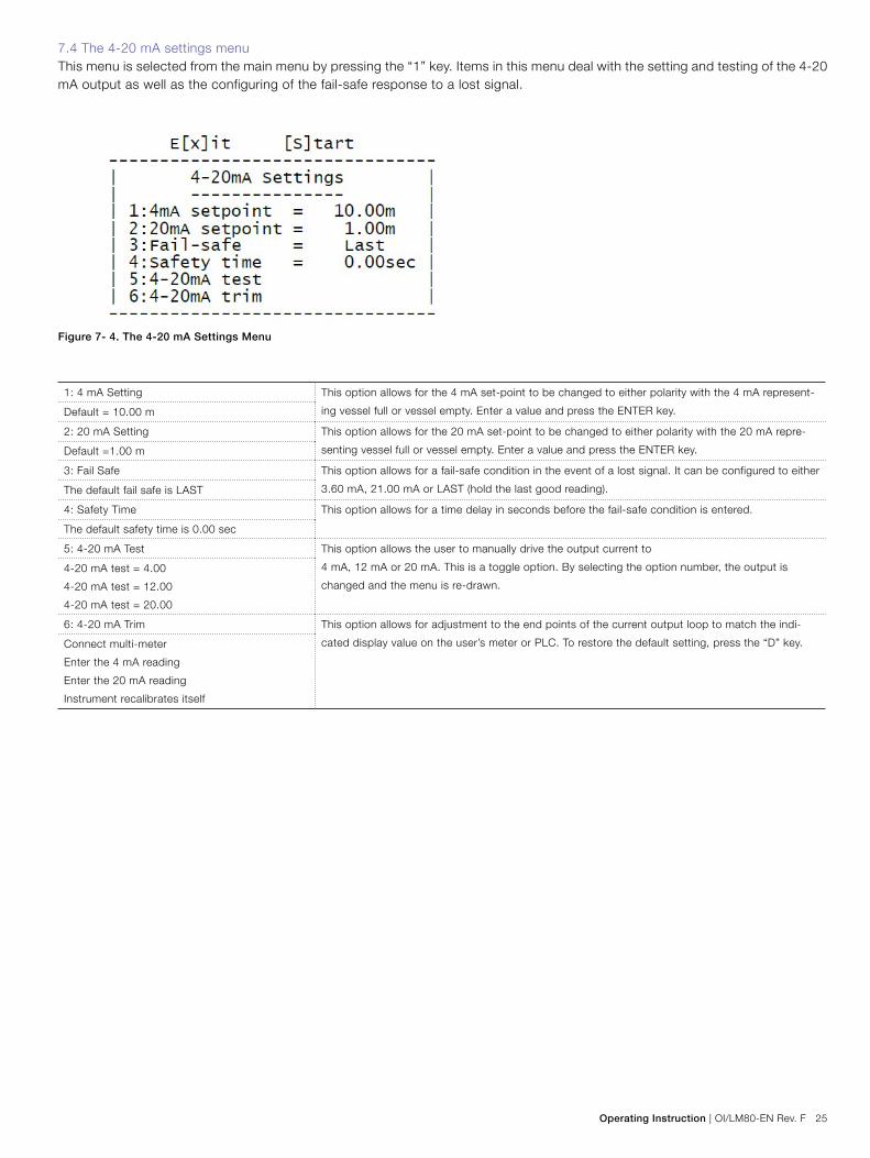
7.4 The 4-20 mA settings menuThis menu is selected from the main menu by pressing the “1” key. Items in this menu deal with the setting and testing of the 4-20 mA output as well as the configuring of the fail-safe response to a lost signal.
Figure 7- 4. The 4-20 mA Settings Menu
1: 4 mA Setting This option allows for the 4 mA set-point to be changed to either polarity with the 4 mA represent-
ing vessel full or vessel empty. Enter a value and press the ENTER key.Default = 10.00 m
2: 20 mA Setting This option allows for the 20 mA set-point to be changed to either polarity with the 20 mA repre-
senting vessel full or vessel empty. Enter a value and press the ENTER key.Default =1.00 m
3: Fail Safe This option allows for a fail-safe condition in the event of a lost signal. It can be configured to either
3.60 mA, 21.00 mA or LAST (hold the last good reading).The default fail safe is LAST
4: Safety Time This option allows for a time delay in seconds before the fail-safe condition is entered.
The default safety time is 0.00 sec
5: 4-20 mA Test This option allows the user to manually drive the output current to
4 mA, 12 mA or 20 mA. This is a toggle option. By selecting the option number, the output is
changed and the menu is re-drawn.
4-20 mA test = 4.00
4-20 mA test = 12.00
4-20 mA test = 20.00
6: 4-20 mA Trim This option allows for adjustment to the end points of the current output loop to match the indi-
cated display value on the user’s meter or PLC. To restore the default setting, press the “D” key.Connect multi-meter
Enter the 4 mA reading
Enter the 20 mA reading
Instrument recalibrates itself

26 OI/LM80-EN Rev. F | Operating Instruction
1: Relay A open This option determines the distance at which relay A will open.
= 1.00 m
2: Relay A closed This option determines the distance at which relay A will close.
= 2.00 m
3: Relay A test This option allows the user to manually drive the relay output to Open or Close. This is a toggle op-
tion. By selecting the option number, the output is changed and the menu is redrawn.Not active
4: Relay B open This option determines the distance at which relay B will open.
= 4.00 m
5: Relay B closed This option determines the distance at which relay B will close.
= 5.00 m
6: Relay B test This option allows the user to manually drive the relay output to Open or Close. This is a toggle op-
tion. By selecting the option number, the output is changed and the menu is redrawn.Not active
7.6 The Instrument settings menuThe Instrument Setting Menu allows selecting the operating program, units and adjusting the position of the LM80. For example to change the units:
1. Hit space bar to get main menu and the "3" key to get the Instrument Settings menu
Figure 7- 6. The Instruments Settings Menu
Items in this menu deal with the configuration of the LM80 laser level transmitter. This menu also shows the internal temperature of the unit and the signal strength of the last reading taken.
7.5 The relay settings menuThis menu is selected from the main menu by pressing the “2” key. Items in this menu deal with the setting and testing of the relay outputs.
Figure 7- 5. The Relay Settings Menu

Operating Instruction | OI/LM80-EN Rev. F 27
Figure 7- 7. The Instrument Settings Menu
3. To change meters to feet, hit the “2” key on keyboard. To go back to the main menu, hit the “x” key.
1: Program This option can take on the value of 0-4. It allows for the selection of a program that suits a
particular application. The program description is displayed adjacent to the program number. Full
details of the program parameters are given in a later section.
Default
0 = Standard
1 = Light Dust
2 = Heavy Dust
3 = Position
4 = Custom
2:Units
Default = meters
This option allows for the selection of measuring units in either feet or meters. This is a toggle op-
tion. By selecting the option number, = meters the units are changed.
3: Datum trim
Default = 0.00 m
This option allows the instrument datum to be adjusted by up to +1 m or –1 m. To change the
value, enter the value that you want the instrument to read shorter or longer and press the ENTER
key.
Standard: This program is for demonstration purposes or dust free applications. This program does not use
“variable gain” feature.
Light Dust: This is most commonly used program. When running in light dust mode, the laser uses “Variable
gain” for better signal separation and better performance in applications with Light and Moderate
dust.
Heavy Dust: This program is similar to Light Dust Program. The difference is that Heavy Dust program uses
more filtering and additional features for measurement in environment with moderate to heavy dust.
Position: This program is designed for positioning applications (tracking the movement of machinery such as
overhead cranes, tripper cars, stackers, reclaimers etc.)
Custom: This program can be configured by the end-user for specific applications, which re-quire different
parameters. Such applications are rock crushers, small process Hoppers, etc.
7.7 Application settings and application tablePrograms are application-oriented modes of operation. Please set the correct program according to your application, see ap-plication table on page 29 for details.

28 OI/LM80-EN Rev. F | Operating Instruction
Application Type Application
Example
Settings Notes
Program Buffer Keep Environment Fill Rate
Storage silo/bin with min
or light dust or no dust
during fill
Granular plastics silo Light Dusts Default Default Dust Default
Storage silo with moder-
ate or heavy dust during
fill dust settles on dis-
charge
• Coal bunkers, grain silos,
powders
• Roofing granular silos
• Wood chip silos
Heavy Dust Default Default Dust Set fill rate
in m/min or
ft/min.
The rate at which
the level is changing
when filling or empty-
ing the silo.
Silo/bin with rapid level
movement and erratic
material surface, light
dust
• Crusher
• Surge Bin
• Process Hopper - granu-
lar plastics
• Granular food, dog food,
cat food
Custom 8 to 12 1 to 2 Dust Default
Opaque Liquids • Lift station - sewer
• Ink
• Polymers
Standard 8 to 16 4 to 6 Dust Default
Semi-Clear Liquids • River Water
• Sea Water
Standard 8 to 16 4 to 6 Normal Default
Reactor vessel, laser
measures through sight
glass
• Devolitizer reactor
• Molten Plastic
Custom 8 to 16 1 to 2 Dust Use only ABB sup-
plied sight glass
HPSG. Use ABB
cooling tubes, P802
for mounting laser.
Contact factory for
details.
Positioning indoor min or
no dust
• Tripper car in powder
plant or grain elevator
Positioning Default Default Normal Default When laser unit is
used for positioning
applications, it will
be shipped from the
factory as part of
the positioning kit.
Maximum range will
be set at 150 m, this
can be changed in
the advanced settings
menu.
Positioning indoor some
dust / smoke
• Overhead crane in ce-
ment plant, mine, steel
plant
Positioning Default Default Dust Default
7.8 Laser application / setup table
Parameter Program 0 Program 1 Program 2 Program 3 Program 4
A:Parameter Name Standard Light dust Heavy dust Position Custom
B:Fill rate 0.00m/min 1.20m/min 0.24m/min 0.00m/min 0.00m/min
C:Empty rate 0.00m/min 0.00m/min 0.00m/min 0.00m/min 0.00m/min
D:Pointer On at start On at start On at start On at start On at start
E:Range Blank 0.00m 0.00m 0.00m 0.00m 0.00m
F:Buffer 8 20 25 2 16
G:Keep 2 2 2 2 16
H:Environment Normal Dust Dust Dust Dust
I:Resolution High High High High High
J:Pause 0 sec 1 sec 2 sec 0 sec 0 sec
Below table shows the default settings of each program. These default parameters are set in factory and can be modified but only with the help of ABB
trained personnel.

Operating Instruction | OI/LM80-EN Rev. F 29
7.9 The laser configuration device LCD2
The LCD2 Configuration Device gives the user access to the settings outlined in the table on the following page. As soon as the LCD2 is plugged into the communication port it begins dis-playing the distance measured as well as the 4-20 mA current output. Pressing the EXIT key stops the LM80 Level Transmit-ter from running and provides access to a list of menu options. Each menu item is associated with a single parameter that can be changed. There are three types of parameters, each of which is changed in a slightly different way.
7.9.1 Changing numeric values
• To scroll between the menus use the or keys.• To edit the value within a menu or access a test function
press the ENTER key.• To select a digit to edit use the and keys.• To edit a digit use the or keys.• To save the new value and stop the editing mode press the
ENTER key.• To ignore the new value and stop the editing mode press
the EXIT key.• To restart the LM80 laser level transmitter in normal mea-
suring mode press the EXIT key.
7.9.2 Activating a test function
• To scroll between the menus use the or keys.• To access a test function press the ENTER key.• To select between test states use the and keys.• To stop the editing mode press the ENTER key or the EXIT
key.• To restart the LM80 laser level transmitter in normal mea-
suring mode press the EXIT key.
7.9.3 Selecting from a list of options• To scroll between the menus use the or keys.• To access an option press the ENTER key.• To scroll between options use the and keys.• To save the new option and stop the editing mode press
the ENTER or the EXIT key.• To restart the LM80 laser level transmitter in normal mea-
suring mode press the EXIT key.• Where a setting is changed from a list of options, the new
value is always stored. There is no EXIT without saving.

30 OI/LM80-EN Rev. F | Operating Instruction
Display Editing keys Description
Plug LCD2 into
LM80
12.34 m 17.65 mA
12.35 m 17.66 mA
Cannot be edited Displays the distance and output in mA
EXIT 4 mA Setpoint
0020.00 m
- select digit
- change digit
Distance associated with a 4 mA output
20 mA Setpoint
0001.00 m
- select digit
- change digit
Distance associated with a 20 mA output
4-20 mA Test
12.00 mA
- select digit
current
Forces the output to a selected current
value
Fail Safe
Last, 3.6 mA, 21 mA
- select mode Sets the response to a lost signal condition
Safety Time
0000.00 sec
- select digit
- change digit
Sets the response time to a lost signal
Relay A Open
0001.00 m
- select digit
- change digit
Distance associated with the opening of
Relay A
Relay A Closed
0002.00 m
- select digit
- change digit
Distance associated with the closing of
Relay A
Relay A Test
Open, close
- select relay state Forces Relay A into a selected state
Relay B Open
0004.00 m
- select digit
- change digit
Distance associated with the opening of
Relay B
Relay B Closed
0005.00 m
- select digit
- change digit
Distance associated with the closing of
Relay B
Relay B Test
Open, close
- select relay state Forces Relay B into a selected state
Program
Standard, light dust, heavy dust,
positioning, custom
- select program Sets the mode of operation from a list of
preset options
Units
meter, feet
- select unit Sets the units of distances for all set points
Datum
0000.00 m
- select digit
- change digit
Applies an offset to all distance readings.
Note that LCD2 cannot set negative trim.
But this is possible with PC.
Exit 12.34 m 17.65mA
12.35 m 17.66mA
Cannot be edited Restarts the LM80

Operating Instruction | OI/LM80-EN Rev. F 31
7.10 Troubleshooting
Symptom Fault Correction
Unit Dead • Not currently connected • Check Connections
• 24 V DC +- 10% - Check Power Input
• Check the Polarity of the power connections
• Check 4-20 mA Connection is Dedicated to the
Laser Instrument and no other Instrument
• Check correct grounding
• Contact ABB for repair
Incorrect 4-20 mA
Current Loop Output
• Check the Distance Readout Using the RS232 Serial Output into a PC or LCD2
Correct Reading on
Serial Port but
incorrect 4-20 mA on
PLC or SCADA
• Incorrect Scaling of PLC or Instrument • Check that the 4 and 20 mA DC Scales are the
Same on the Instrument and the PLC
• Electric Interference from closely laid power supply
Cables
• Re-route the Cable or Screen the Cable
• Adjust trim as needed.
• Incorrect Connection to PLC through Isolator • Check Circuit Diagram on the Isolator
Incorrect Reading on
Serial Port
• Dirt or Obstruction on the Lenses Check that Lenses
are Clean
• Check that Lenses are Clean
• Clean lenses
• Dust or Obstruction in Application • Check the Application: Can you see Surface?
• Check for the Correct Settings for Dusty Environ-
ment; test with heavy dust.
• Laser Might Not Be Aiming at Target • Check that Laser is aiming at the target all the way
(pointer on target)
Unit is Erratic • Unit might not be aiming at target • Check the instrument is aiming at the target all the
way (pointer on target)
• Electric interface from closely laid power supply
cables
• Bad grounding connection
• Re-route the cable or screen the cable
• Make sure ground connection is tight and leads to
proper earth ground.
• Dust or obstruction in application • Check the application: can you see surface?
• Check for correct settings for dusty environment. Try
heavy dust.
• Incorrectly Programmed • Check that output is as smooth as possible. Try
alternate programs in Instrument Setting mode.
• Use averaging to smooth, example waveson water.

32 OI/LM80-EN Rev. F | Operating Instruction
Appendix A Accessories
A.1 AccessoriesBelow tables provide details on the accessories of the LM80 Level Transmitter.For more details, please refer to the LM80 Level Transmitter Data Sheet.
Dust tubes (P801)
Base plate diameter 140 mm (5.51 in) mounts on LM80 standard flange
Length 257.2 mm (10.125 in)
Material 304 Stainless Steel
Function Static air space prevents dust buildup, can be purged (3-5 psi)
Mounting plates
Nominal diameter 4 in / DN 100 6 in / DN 150
Part number P804 P806
Outer diameter 228 mm (8.96 in) 284 mm (11.18 in)
Mounting bold pattern Dual pattern ANSI/DIN
ANSI class 150 : 8 bolts, size 5/8 in, bolt circle 7.5 in
DIN PN 10 : 8 bolts, size 18 mm, bolt circle 180 mm
Dual pattern ANSI/DIN
ANSI class 150 : 8 bolts, size 3/4 in, bolt circle 9.5 in
DIN PN 10 : 8 bolts, size 22 mm, bolt circle 240 mm
Material 304 Stainless steel
Pressure rating No pressure rating, atmospheric pressure only
Mounting flanges
Nominal diameter 4 in raised face 6 in raised face DIN 100 DIN 150
Part number F804 F806 F810 F815
Outer diameter 9 in 11 in 220 mm 285 mm
Mounting bold pattern ANSI class 150
8 bolts, size 5/8 in
Bolt circle 7.5 in
ANSI class 150
8 bolts, size 3/4 in
Bolt circle 9.5 in
PN 10
8 bolts, size 18 mm
Bolt circle 180 mm
PN 10
8 bolts, size 22 mm
Bolt circle 240 mm
Material 304 Stainless steel
Pressure rating No pressure rating, atmospheric pressure only
Adjustable swivel flange (S800)
Outer diameter 180 mm (7.1 in)
Mounting bolt pattern 4 bolt holes, 8.5 mm (0.33 in) diameter, bolt circle 160 mm (6.29 in)
Height 25.4 mm (1 in)
Tilt angle for aiming Continuously adjustable from 0° to 6°
Material Aluminum
Cooling tubes (P802)
Base plate diameter 140 mm (5.51 in) mounts on LM80 standard flange
Mounting plate diameter 140 mm (5.51 in) compatible with LM80 mounting accessories
Length 260.4 mm (10.25 in)
Material 304 Stainless Steel
Function Offset from hot process interface to allow convection cooling,
can be purged

Operating Instruction | OI/LM80-EN Rev. F 33
Adjustable pivot bracket (A800)
Outer diameter / width 160 mm (6.3 in)
Opening diameter 90 mm (3.54 in)
Mounting plate thickness 4.76 mm (0.19 in)
Mounting bolt HHCS screw 5/16-18, bolt hole 8.33 mm (0.33 in)
Height of pivot 25.4 mm (1 in)
Tilt angle for aiming Continuously adjustable over 180°
Material 304 Stainless steel
Available Optional Items
HPSG High pressure sight glass
LCD2 Communication/configuration device and local display for programming and demo purposes. Note:
Programming can also be implemented with desktop PC or laptop. Note: Not rated for explosive dust or
gas / cannot be used in hazardous area.
USBR RS232 to USB cable for configuring LM80 using a laptop or desktop computer Note: Not rated for
explosive dust or gas / cannot be used in hazardous area.
REFL Reflective panel for positioning applications up to 150 m
GCK Set of 2 Ex cable glands with ½ inch NPT thread, size 0 / 8 mm and size 00 / 12 mm
GC1 Exd/e Flameproof imperial to metric adapter, ½ inch NPT to M20, enables use of metric M20 threaded
conduits or cable glands with LM80
A.2 Dust tubes (P801)The dust tube is a very simple and effective device designed to prevent dust from settling on the laser lens. The LM80 Level Transmitter will adapt to most dust-present applications by successfully using the dust tube. However, if the dust level is very high, ABB recommends using the air purge set to 3-5 psi.
Figure A- 1. Cooling and Dust Tubes
A.3 Cooling tubes (P802)The cooling tubes are installed to offset the LM80 from the hot process interface to allow convection cooling. They can be purged.
A.4 LCD2 configuration deviceThis accessory can be used to enter settings and perform inter-face testing. Advanced features such as program parameters cannot be set and must be accessed from a PC or a Laptop.
Figure A- 2. LCD2 Configuration Device

34 OI/LM80-EN Rev. F | Operating Instruction
Appendix B Extended software settings
B.1 Extended menuThe purpose of this addendum is to document the advanced settings available in the hidden menus of the LM80 laser level transmitter. These advanced settings allow the LM80 to be tai-lored to specific applications where the standard settings are not sufficient.
Changing parameters can render the Level Transmitter inoperable. Be very careful. In case the level Transmitter does not function anymore after a parameter adjustment attempt, default factory settings have to be restored. For further adjustments, please contact ABB.
Please be careful when modifying the default factory settings, enabling the laser pointer using a PC or the LCD2 means the instrument is now in service mode and thus a class 3R device.
Some important facts:LM80 can communicate with PC, Laptop or LCD2.
The LCD2 (Laser communication device) is created for fast and easy communication with LM80 without the need to connect computer. LCD2 does not have its own power source and does not require set-up. The communication to the LM80 laser level transmitter is conducted from the moment LCD2 is connected to the LM80.
The LCD2 is designed to provide a simple and easy to use interface to the LM80 but contrary to a PC or Laptop cannot access the advanced menus.
LM80 laser level transmitters have different modes of operation called PROGRAMS. The parameter Program is found under option 3.Instrument Settings in the Main Menu. Below is a short de-scription of each program: – Standard- this program is for demonstration purposes or
dust free applications. This program does not use variable gain feature.
– Light Dust – this is most commonly used program. When running in light dust Mode, the laser uses variable gain for better signal Separation and better performance in appli-cations with Light and Moderate dust.
– Heavy Dust - this program is very similar to Light Dust Pro-gram. The only difference is that Heavy Dust program uses
more filtering and additional features for measurement in environment with moderate to heavy dust.
– Position - is designed for positioning applications (tracking the movement of machinery such as overhead cranes, trip-per cars, stackers, reclaimers etc.)
– Custom - this program can be configured by the end-user for specific and atypical applications, which require differ-ent parameters set-up. Such applications are rock crush-ers, small process Hoppers, etc.
B.2 Passwords for advanced settings
All passwords must be entered with low case letters only.Password “agent”
Password agent allows the end-user to enter the AGENT SET-TINGS menu. While in this menu, the end-user can access any of the above described programs (application oriented mode of operations) and change some of the parameters. However it is highly recommended changes to be made to CUSTOM pro-gram only, when required. Rest of the programs which actually are application-oriented modes of operation are already preset for the applications, based on field experience.
The STANDARD program is recommended for demonstration purposes since it provides the fastest response time. The light dust and heavy dust programs makes use of fill rate and empty rate settings which slow down the response time of the LM80.

Operating Instruction | OI/LM80-EN Rev. F 35
B.3 Agent Settings menu description and operation – In Main Menu press p on the keyboard. On the prompt
Password, enter agent (low case letters only) and then press Enter
[S]tart---------------------------------------------------------------
+ LM Family ++ Number AA00191 Rev 2.20 ++ Main User Settings Menu ++ ----------------------------------------------- ++ ++ 1:4-20mA Settings ++ 2:Relay Settings ++ 3:Instrument Settings ++ ++ +
+++++++++++++++++++++++++++++++++++++++ Password: agent
– Next will appear the AGENT SETTINGS menu
--------------------------------AGENT SETTINGS--------------------------------Program 0: Standard => ActiveProgram 1:Light Dust => InactiveProgram 2:Heavy Dust => InactiveProgram 3: Position => InactiveProgram 4: Custom => InactiveY: Diagnostic=> Inactive--------------------------------X: ExitEnter program to edit:
The access to every program is done by typing the corre-sponding program number, for example, to access the Stan-dard program menu, press 0. On the screen will appear the Standard program menu
B.4 Program 0: standard parameters description:
Standard Program - default settings.Parameters comments:
--------------------------------PROGRAM 0: STANDARD PARAMETERS--------------------------------A: Program name = StandardB: Fill rate = 0.00 - Maximum filling rate in meters or feet
per minute; when this setting is used any change in level that is faster than the fill rate will be smoothed out, this filters out fast transients from the results
C: Empty rate = 0.00 - Maximum emptying rate in meters or feet per minute; when this setting is used any change in level that is faster than the empty rate will be smoothed out, this filters out fast transients from the results.
D: Pointer = On at startup - Toggle between "On" and "On at startup", determines when the red pointer is on. By default the red pointer will come on and flash for 2
minutes at startup then switch off. If this parameter is set to ON the pointer will flash continuously. Note that this behavior can be changed in the factory menu.
E: Range blank = 0.00 - Distance in meters or feet (depending on units setting) at which the LM80 may lose signal. in silos with polished walls, such as the stainless steel vessels in the Food processing Industry, the laser may lose signal when it hits the silo wall, especially in the silo cone. When the laser loses signal, it will switch to Fail Safe Mode. If range blank is set to the distance where the laser may “see” polished wall (usually on emptying part of the process) and lose signal, then the device will not switch to Fail Safe Mode. It will continue reporting the distance at which the signal was lost until a new signal is received.
F: Buffer = 9 - Size of the rolling buffer. Must be a value between 0 and 25
G: Keep = 7 - Number of readings to keep in the averaging buffer. Readings are removed starting with the shortest reading. The number must be a value between 0 and the value entered for the F: Buffer parameter
H: Environment = Toggle between Normal and Dust. The Environment parameter can be set to either "Normal" or "Dust" for any of the preset programs. When set to Normal level measurements are performed using fixed gain whereas when set to Dust measurements are performed using variable gain.
I: Resolution = High - Toggle between High and Low, Low is used to provide faster response time.
J: Pause = 0 - pause time in seconds between readings, must be a value between 0 and 255
X: Exit Enter selection:

36 OI/LM80-EN Rev. F | Operating Instruction
B.4.1 Factory settings menu description and operation
This menu cannot be accessed with LCD2 com-munication device. To enter the password and access the extended menu, communication with LM80 must be done using PC or Laptop.
Password “factory” allows the user to access the FACTORY MENU extended menu. FACTORY MENU is created mainly for factory trained manufacturing and repair personnel. In this Ad-dendum option
Special Settings and Hardware Settings will be describedIn Main Menu press “p” on the keyboard. On the prompt Pass-word, type the password "factory" (low case letters only) and then press Enter
[S]tart--------------------------------------------------------------
+ LM Family ++ Number AA00191 Rev 2.20 ++ Main User Settings Menu +
+ ------------------------------------------------------------++ ++ 1:4-20mA Settings ++ 2:Relay Settings ++ 3:Instrument Settings ++ +++++++++++++++++++++++++++++++++++++++++++
Password: factoryNext will appear the FACTORY MENU
FACTORY MENU00: Upload to EEPROM01: Edit settings02: Edit product name03: Program LCD04: Test crystals05: Test temperature Transmitter06: Test relays and LED's07: Test system noise08: Test laser and receiver09: Special settings10: Hardware settings11: Capture excel dataY: DIAGNOSTICS INACTIVEX: EXIT
Enter Selection

Operating Instruction | OI/LM80-EN Rev. F 37
HARDWARE SETTING Menu directly relates to the settings of fpga chip, which controls the fun-damental hardware functionality of the laser unit. CHANGE ONLY THE PARAMETERS SPECIFIED IN THIS ADDENDUM. CHANGE OF ANY OTHER PARAMETER MAY RENDER THE UNIT INOPER-ABLE.
B.4.2 Hardware settings
At the Enter selection prompt type 10 to access the Hardware settings menu. A second prompt Password will appear. Type password fpga (low case letters only) and press ENTER. This is the password for enter Hardware settings menu:
Settings B, C, D, E and I are factory settings and should not be modified.
Password: fpga
--------------------------------HARDWARE SETTINGS--------------------------------A:Range = 1 (46.83m)B:Laser pump = 79C:APD pump = 60D:Xtal A start = 230E:Xtal B High Res start = 55F:Xtal B Low Res start = 84G:Sweep limit = 50H:User setpoint limit[m] = 30I:4-20mA trim values = 620.05 3250.77X:Exit
The hardware menu is used to change the measuring range of the LM80 level transmitter; this range is set to 30 m at the factory. The "H:User setpoint limit" is used to change the mea-suring range and should be set to the range required by the application. The "A:Range" setting will be automatically ad-justed to the lowest range that contains the value entered into the "H:User setpoint limit" parameter (see table below). Care should be taken when adjusting the "H:User setpoint limit" be-cause the response time of the LM80 is related to the selected range; e.g. the higher the range the slower the response.
[i] Even though the "H:User setpoint limit" can be set to much higher values, in practice the LM80 is limited to a range of about 100 m for most surfaces and 150 m with a reflector. Attempting to measure further will result in unreliable performance.
The hardware menu can also be used to modify the laser out-put power with the "B:Laser pump" setting. Increasing this set-ting can sometimes help the LM80 penetrate further into fog or dust. The maximum value for this parameter is 150.
Range 1 2 3 4 5
Max distance in m 46.83 93.66 187.32 374.64 749.28
Max distance in ft 153.6 307.2 614.4 1228.8 2457.6
38 OI/LM80-EN Rev. F | Operating Instruction
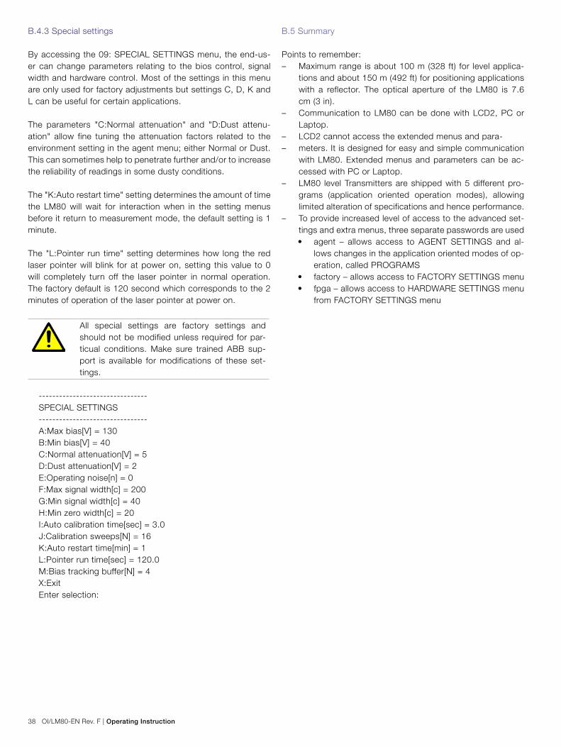
B.4.3 Special settings
By accessing the 09: SPECIAL SETTINGS menu, the end-us-er can change parameters relating to the bios control, signal width and hardware control. Most of the settings in this menu are only used for factory adjustments but settings C, D, K and L can be useful for certain applications.
The parameters "C:Normal attenuation" and "D:Dust attenu-ation" allow fine tuning the attenuation factors related to the environment setting in the agent menu; either Normal or Dust. This can sometimes help to penetrate further and/or to increase the reliability of readings in some dusty conditions.
The "K:Auto restart time" setting determines the amount of time the LM80 will wait for interaction when in the setting menus before it return to measurement mode, the default setting is 1 minute.
The "L:Pointer run time" setting determines how long the red laser pointer will blink for at power on, setting this value to 0 will completely turn off the laser pointer in normal operation. The factory default is 120 second which corresponds to the 2 minutes of operation of the laser pointer at power on.
All special settings are factory settings and should not be modified unless required for par-ticual conditions. Make sure trained ABB sup-port is available for modifications of these set-tings.
--------------------------------SPECIAL SETTINGS--------------------------------A:Max bias[V] = 130B:Min bias[V] = 40C:Normal attenuation[V] = 5D:Dust attenuation[V] = 2E:Operating noise[n] = 0F:Max signal width[c] = 200G:Min signal width[c] = 40H:Min zero width[c] = 20I:Auto calibration time[sec] = 3.0J:Calibration sweeps[N] = 16K:Auto restart time[min] = 1L:Pointer run time[sec] = 120.0M:Bias tracking buffer[N] = 4X:ExitEnter selection:
B.5 Summary
Points to remember: – Maximum range is about 100 m (328 ft) for level applica-
tions and about 150 m (492 ft) for positioning applications with a reflector. The optical aperture of the LM80 is 7.6 cm (3 in).
– Communication to LM80 can be done with LCD2, PC or Laptop.
– LCD2 cannot access the extended menus and para- – meters. It is designed for easy and simple communication
with LM80. Extended menus and parameters can be ac-cessed with PC or Laptop.
– LM80 level Transmitters are shipped with 5 different pro-grams (application oriented operation modes), allowing limited alteration of specifications and hence performance.
– To provide increased level of access to the advanced set-tings and extra menus, three separate passwords are used • agent – allows access to AGENT SETTINGS and al-
lows changes in the application oriented modes of op-eration, called PROGRAMS
• factory – allows access to FACTORY SETTINGS menu• fpga – allows access to HARDWARE SETTINGS menu
from FACTORY SETTINGS menu
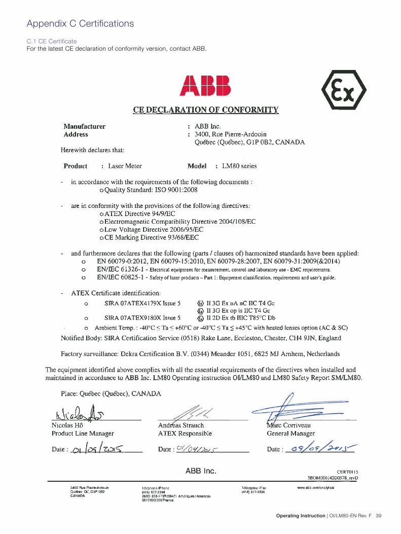
Operating Instruction | OI/LM80-EN Rev. F 39
Appendix C Certifications
C.1 CE CertificateFor the latest CE declaration of conformity version, contact ABB.

40 OI/LM80-EN Rev. F | Operating Instruction
C.2 CSA Certificate
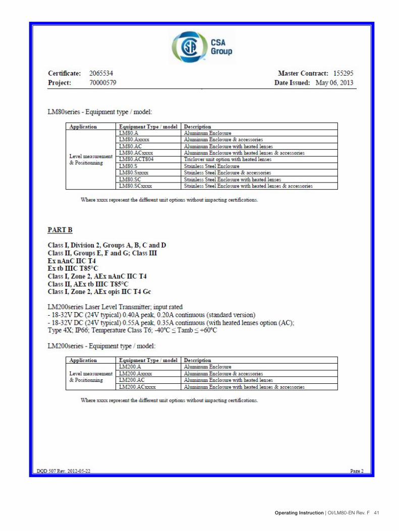
Operating Instruction | OI/LM80-EN Rev. F 41

42 OI/LM80-EN Rev. F | Operating Instruction
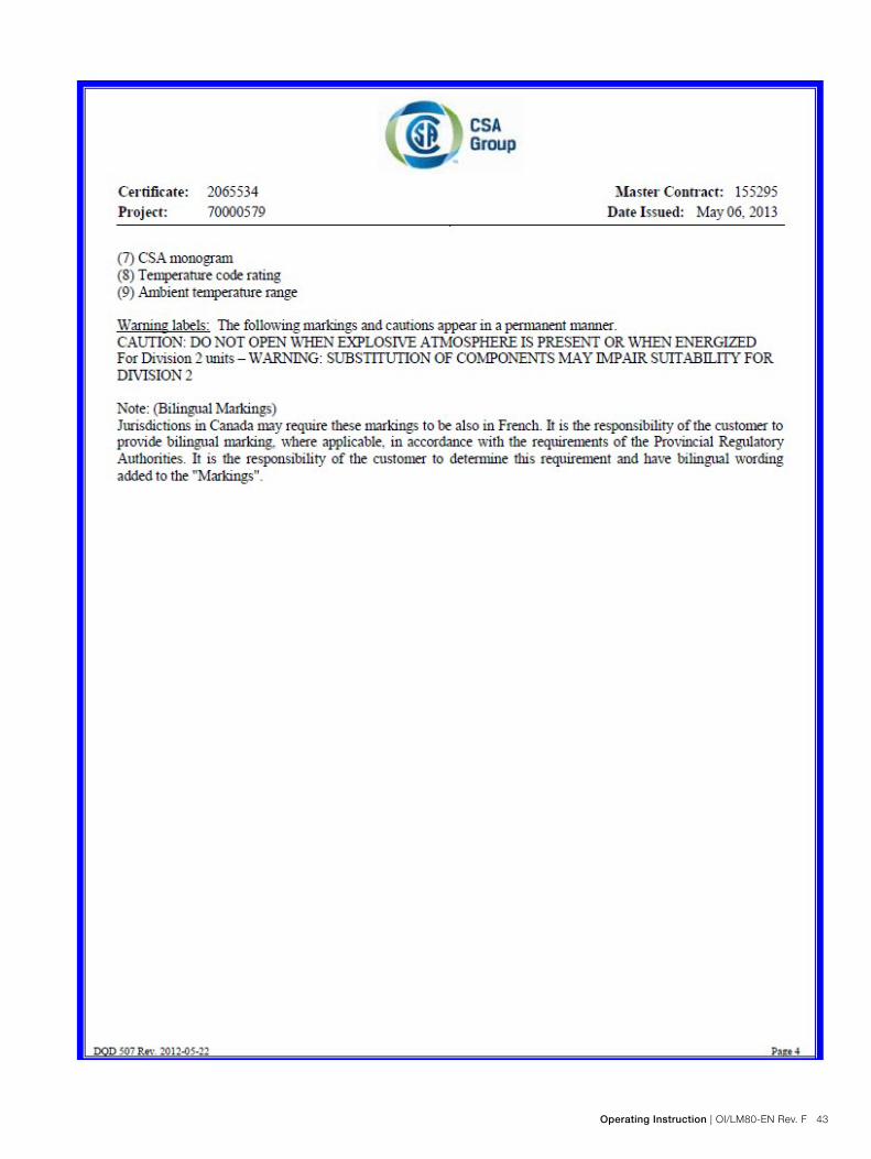
Operating Instruction | OI/LM80-EN Rev. F 43

44 OI/LM80-EN Rev. F | Operating Instruction
C.3 FM Certificate

Operating Instruction | OI/LM80-EN Rev. F 45

46 OI/LM80-EN Rev. F | Operating Instruction
Notes

Operating Instruction | OI/LM80-EN Rev. F 47
Notes

OI/
LM80
-EN
Rev
F
9.20
15
Contact us
Note
We reserve the right to make technical changes
or modify the contents of this document without
prior notice. With regard to purchase orders, the
agreed
particulars shall prevail. ABB does not accept
any responsibility whatsoever for potential errors
or possible lack of information in this document.
We reserve all rights in this document and in
the subject matter and illustrations contained
therein. Any reproduction, disclosure to third
parties or utilization of its contents - in whole
or in parts – is forbidden without prior written
consent of ABB.
Copyright© 2015 ABB
All rights reserved
3KXL312002R4201
ABB Inc. Measurement & Analytics3400, Rue Pierre-ArdouinQuébec (Québec) G1P 0B2CanadaFor North America: +1 800 858 3847For all other countries: +1 418 877 8111e-mail: [email protected]
ABB Inc.Process Automation 18321 Swamp RoadPrairieville, LA 70769 USAPhone: +1 225 673 6100Service: +1 225 677 5836Fax: +1 225 673 2525Service e-mail: [email protected]
ABB LimitedProcess AutomationHoward RoadSt. NeotsCambridgeshire PE19 8EUUKTel: +44 (0)1480 475321Fax: +44 (0)1480 217948
ABB South Africa (Pty) Ltd Process Automation 2 Lake RoadLongmeadow Business Estate (North)Modderfontein 1609GautengSouth AfricaTel: +27 10 202-5000Fax: +27 11 579-8000
www.abb.com/level
ABB LimitedProcess Automation14 Mathura RoadP.O. Amar NagarFaridabad 121003HaryanaIndiaTel: +91 129 227 5591-92Fax: +91 129 227 9692, +91 129 227 5019
ABB Australia (Pty) LtdProcess Automation139 Coronation Drive, level 3MiltonQueensland 4064AustraliaTel: +61 7 3332 0711Fax: +61 7 3332 0701
Sales
Service


![Minor Project-laser Torch-based Voice Transmitter and Receiver[1]](https://img.dokumen.tips/doc/110x75/551ffef1497959892f8b4616/minor-project-laser-torch-based-voice-transmitter-and-receiver1.jpg)