Embed Size (px)
Citation preview

Laser Induced Florescence (LIF) Technique and ItsApplication for Flow Visualization and Scalar Field
(Temperature or Concentration ) Measurement
Hui HU, Toshio KOBAYASHI,Tetsuo SAGA and Nubuyuki TANIGUCHI
Institute of Industrial Science, University of Tokyo,Roppongi 7-22-1, Tokyo 106-8558, Japan

Laser Induced Florescence (LIF) Technique
Energy level
E1
E2
photon
Absorb energyfrom laser light
LIF emission
Spectrum of fluorescent dye (Rhohdamine B)
Hf ( x0,y0) : measured fluorescence intensity A: the fraction of the fluorescence light collected by camera. quantum efficiency, L: the length of the sampling volume along the path of excitation beam molar absorptivity C(x0,y0): the molar concentration of the fluorescent dye. I(x0,y0): the intensity of excitation light beam at the point (x0,y0 )
The intensity of the LIF light at point (x0,y0)
),()(),(),( 000000 yxLCTAyxIyxH f εΦ=
:Φ
:ε
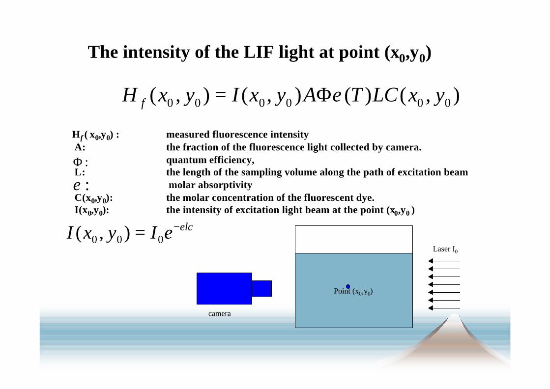
lceIyxI ε−= 000 ),(
Point (x0,y0)
camera
Laser I0

LIF Technique for fluorescent dye concentration measurement
),()(),(),( 000000 yxLCTAyxIyxH f εΦ=
),(),( 0000 yxCyxH f ∝
Keep flow temperature and measurementsystem parameters in constant

Calibration profile for concentration measurement
0
0.2
0.4
0.6
0.8
1
0 0.2 0.4 0.6 0.8 1
C/C0 , C0=0.3mg/l
(I-I
b)/(
I0-I
b)
Laser power=highLaser power=middleLaser power=lowTheory Value
(Hu et al. 1998)

Concentration measurement results
Circular jet flow(Hu et al. 1998)

Concentration measurement results
Lobed jet mixing flow(Hu et al. 1998)
Lobe trough sliceLobe peak slice

LIF Technique for flow temperature field measurement
),()(),(),( 000000 yxLCTAyxIyxH f εΦ=
)(),( 00 TyxH f ε∝
Keep fluorescent dye concentration andmeasurement system parameters in constant

Calibration profile for temperature measurement

The shortages for single emission LIF technique
s Complex calibration• uniformity of laser sheet• the laser power changing between the calibration
test and experiment• absorption effect of the fluorescent dye• etc.
),()(),(),( 000000 yxLCTAyxIyxH f εΦ=
lceIyxI ε−= 000 ),(
The attenuation effect of laser light
laser power 2.5w
0
0 .2
0 .4
0 .6
0 .8
1
1 .2
0 50 100 150 200 250L length (mm)
H(X
)/H
(0)
c0:1g;1250l
c0:1g:100l
Point (x0,y0)
camera
Laser I0
lceIyxI ε−= 000 ),(
(Hu et al. 1998)

),(),(),(),( 0011100001 yxLCTAyxIyxH f λεΦ=
Dual emission LIF technique:
222
111
2
1 )(),(
),(
ΦΦ
∝c
cTyxH
yxH
f
f
εε
),()(),(),( 0022200002 yxLCAyxIyxH f λεΦ=

the measurement results from a singleemission and dual emission LIF technique

Dual emission LIF technique
(Sakakibara et al. 1999)

PIV-PLIF System for velocity and temperature orspice simultaneous measurement
velocity vectors from PIV and temperature distribution (background) form PLIF )(Hart et al. 1999)
![g]kfn ;/sf/ s[lif tyf ;xsf/L dGqfno s[lif ljefu s[lif k|;f ...vdd.gov.np/public/kcfinder/upload/files/Norms_Whole_2068.pdf · b'O{ zAb s[lif ljefusf] :yfkgf sfnb]lv g} s[lif k|;f/n]](https://img.dokumen.tips/doc/110x75/5ecbc4accdaccc4d425b8270/gkfn-sf-slif-tyf-xsfl-dgqfno-slif-ljefu-slif-kf-vddgovnppublickcfinderuploadfilesnormswhole2068pdf.jpg)