Embed Size (px)
Citation preview

Managed by UT-Battelle for the Department of Energy
Laser-Assisted Joining Process of Aluminum and Carbon Fiber Components
PIs: Adrian S. Sabau, C. David Warren (ORNL) 2016 DOE Vehicle Technologies Annual Merit Review and Peer Evaluation Meeting
June 07, 2016
Project ID: LM097
Jian Chen, Claus Daniel, Don Erdman III, Harry Meyer III, and
Thomas R. Watkins (ORNL team)
Tim Skszek (Cosma Eng.), Mary M. Caruso (3M), and James Staagaard (Plasan)
This presentation does not contain any proprietary, confidential, or otherwise restricted information.

Managed by UT-Battellefor the Department of Energy
• Project start date: 10/1/2013• Project end date: 12/30/2015• Percent complete: 100%
Barriers Addressed• Dissimilar Material Joining• Rapid/Consistent Joining of
Multi-Material Structures• Manufacturability• Corrosion Prevention
• Total project funding $600,000– DOE share: $600,000– Not required cost-share: $30,000
• Funding received in FY14: $300,000• Funding for FY15: $300,000
Timeline
Budget
• Magna• 3M Company• Plasan Carbon Composites
Partners
Overview
• Clearwater Composites, Inc. • University of Tennessee Knoxville
SubcontractorsWhat’s Next• Proposals have been submitted
for commercial scale-up of these technologies
LM097

Managed by UT-Battellefor the Department of Energy
Relevance to VT Goals Future Automotive Designs will Likely Be Multi-Material
Lightweighting, Joining and Assembly• High Volume, High-Yielding Technologies for dissimilar materials• Joining methods must be rapid, affordable, repeatable and reliable.• Galvanic Corrosion Potential must be mitigated• Safety and Functionality must be maintained.• Adhesive Technology does provide an insulating layer
Current Adhesive Joining Methods are:• Labor Intensive• Variable depending up the person doing the Surface Preparation• Not High Volume Friendly• Not Eco-Friendly (Involve Solvent Cleaning)
Successful Al-CF joining in this project will enable an increase in Multi-Material use in automotive and consequently lead to significant weight reduction thereby reducing greenhouse gas emissions and dependency on foreign oil (Reference: VT Program, Multi-Year Program Plan 2011-2015, Dec 2010, pp. 1.0-2, 2.5-3, 2.5-4.)
LM097

Managed by UT-Battellefor the Department of Energy
Objective: Develop a Breakthrough Joining Technology for Joining Carbon Fiber Polymer Composites (CFPC) and
Aluminum (Al) Components
Goals: Surface preparation of Al and CFPC via laser structuring will:• Increase joint strength,• Reduce variability in surface
preparation,• Elimination of empirical, labor-
intensive surface preparation• Eliminate the use of solvents.• Provide an electrically insulating layer
for corrosion prevention.http://www.extremetech.com/extreme/162582-bmw-i3-will-bmws-new-ev-finally-be-the-breakthrough-for-carbon-fiber-cars
Specific Advantages of laser-structured CFPC and Al: Eliminates sanding Eliminates solvent cleaning Removes resin rich surface layer Provides a greater, non-planar contact area Yields a fiber reinforced adhesive/composite interface Increases Joint ductility by 2X (Crash Energy Absorbance)
CF
AlAHSS
CF
LM097
CF

Managed by UT-Battellefor the Department of Energy
Project Status: Milestones/DeliverablesDate FY14 Milestones/Deliverables Status
12/31/2013 Identified and/or obtained, the Al alloy, composite material system, and the laser ablation wavelengths Complete
3/31/2014 Identified appropriate adhesives and obtained baseline adhesive joint properties (i.e., without laser structuring) Complete
6/30/2014 Demonstrated laser-structuring for CFPC and the aluminum Complete
9/30/14Demonstrated 20% improvement in the lap shear strength of a single-lap joint produced by using Al and CFPC
Go-no-goComplete
12/31/2014 Identified optimum operating parameters for the laser-structuring of Al and laser ablation for CFPC. Complete
3/31/2015 Identified optimum adhesive. Complete
6/30/2015 Demonstrate 20% improvement in lap shear strength of a double lap shear joint produced by using Al and CFPC Complete
9/30/2015
Demonstrate a 40% improvement in the lap shear strength of a lap shear joint produced by bonding aluminum to composites as compared to baseline samples without laser structuring.
Complete
All milestones were successfully completed.
LM097

Managed by UT-Battellefor the Department of Energy
Anatomy of a Typical Adhesive Joint
Metal
CompositeMetal Oxide
Resin Rich Layer (No Fibers)
Adhesive
Bonding Interfaces are: MOx to Adhesive Resin to Adhesive (no fiber reinforcement) Planar (nice place for crack propagation)
SEM of Bonded Composite Panel
Typical Failure Surface
Therefore, Joint properties are those of the Interface
LM097
Managed by UT-Battelle for the Department of Energy
Approach: Aluminum - ORNL Used both Laser-Interference (2-beam) in a Spot by Spot and Rastering for Structuring the Surface
Laser-interference technique systematically “roughens” the surface: •! Constructive interference of two (or more) laser beams intensifies power
creating pits on the surface, •! Destructive interference leaves the surface unchanged Beam 1 Beam 2
Alternating, high-power and low-power profile created by wave interference yields localized melting, solidification, and surface structuring.
Processed region Unprocessed region
LM097

Managed by UT-Battellefor the Department of Energy
UnbondedComposite Surface
The innovations:
Increased surface area; Elimination of surface contaminates; Removal of mold release; Removal of resin rich layer; Fiber reinforcing the interface.
Bonded Composite Surface
Resin
Adhesive
Non-Planar Interface
Fiber Reinforcement
of Interface
Approach: Composites - Both 2 Beam and Rasteringwere used on the CFRC as well.
LM097

Managed by UT-Battellefor the Department of Energy
Results: Surface Cleaning - The Depth Profile for Aluminum Specimens in the As-Received and Laser-Structured
Conditions After N1 shots/spot
0
20
40
60
80
0 50 100 150 200 250 300 350
Al(M) Al(O)C(C-C) C(carb.)O Mg
0
0.5
1
1.5
2
0 50 100 150 200 250 300 350
Na Cl Zn S
00.10.20.30.40.50.6
0 50 100 150 200 250 300 350
Cu Na
Cl Zn
00.10.20.30.40.50.6
0 50 100 150 200 250 300 350
Cu NaCl
After N2 shots/spot
As received
Com
posi
tion
(at%
)
Com
posi
tion
(at%
)C
ompo
sitio
n (a
t%)
Com
posi
tion
(at%
)
Distance from top surface [nm]
Distance from top surface [nm]
Very Effective in Cleaning the Surface
Distance from top surface [nm]
Distance from top surface [nm]
LM097
Solvent Cleaning and Wiping were Eliminated

Managed by UT-Battellefor the Department of Energy
Results: Laser-Structured Joints are more Ductile, Indicating an Enhanced Bonding of Adhesive to Both Al and CFPC
The baseline data shows that the joint is very brittle.
3M provided 3 different adhesives.(Urethane, Acrylic and Epoxy) After testing
AfterTesting
Non-Structured Baseline
Laser Structured
LM097

Managed by UT-Battellefor the Department of Energy
8 shots per spotBonded as-received
6 shots per spot 2 shots per spot
Damaged CF
Undamaged CF
Flat adhesive-resin interface
adhesive in direct contact with CF
Bonded after ablation
Results: Adhesive Composite Interface is Non-Planar and Fiber Reinforced.
Bonded after ablation
Bonded after ablation
LM097

Managed by UT-Battellefor the Department of Energy
SLS strength laser structured vs Raster - all adhesives
620
460810
Adhesive % increase by raster
810 12.7-14.8
460 12.8
620 35.3
Adhesive% increase
Spot-by-spot
810 16.3
460 8.2-12.8
620 25.4
In most cases Rastering was as Effective as Spot-by-SpotLM097
Managed by UT-Battellefor the Department of Energy
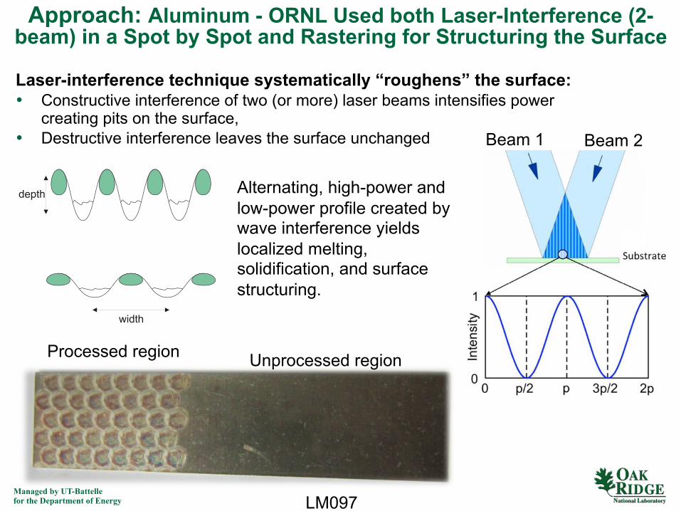
Failure mode changed due to laser-structuring
Baseline joints: 620 adhesive Laser-structured joints: 620 adhesive
Baseline joints: 460 adhesive Laser-structured joints: 460 - adhesive
Both surfaces have residual adhesive
Failure in the composite
Clean fracture surfaces indicate poor adhesive adherence
Baseline = No laser structuring Laser structured joints
Results: Effect of Laser Structuring on Failure Mode
Adhesive – Al Interface Failure Top Ply of Composite Delaminated
LM097

Managed by UT-Battellefor the Department of Energy
Beam Angle
Processing % increase (of mean)
3 2B-raster 14.83 3B-raster 12.73 3C-spot 16.3
12 3B-raster 1612 2C-raster 17.6
Discussion: Evaluated the Effects of Several Variables (Representative Data from Large Data Sets. Processing was various
conditions.)Beam Angle (Slight Effect)
RasteringID
Number
% lap shear increase (of mean)
% load increase (of mean)
1-1b-A 10.8 14.82-1b-B 17.8 23.43-1b-C 21.2 17.84-1b-D 22.7 18.46-1b-D 23.7 20.3
Interference ID Number
% lap shear increase (of mean)
% load increase (of mean)
2B_6 22.2 16.33C_6 19 154D_6 18 12.7
RasteringVS
Interference(Some
indicationrastering
may be better)
Beam size [mm]
Processing % increase shear lap (of mean)
4 2B 14.64 4D 12.34 3C 16.56 4D 16.16 3C 17.46 2B 22.2
Beam Size: 6 mm was somewhat better
LM097

Managed by UT-Battellefor the Department of Energy
Results: Evaluated Double Lap Shear vs Single Lap Shear for Ablated Samples, [0.25 mm, 6mm beam, 810 Adhesive]
Laser Structured Samples still showed a significant increase in ductility.
And
50% of the samples failed in the bulk of the aluminum away from the joint.
LM097

Managed by UT-Battellefor the Department of Energy
Processing % shear lap increase (of mean)
2B-6 (.85) 31.5
3C-6 (.85) 34.8
4D-6 (.85) 40.1
2B-6 (.25) 22.2
3C-6 (.25) 17.6
4D-6 (.25) 16.0
Results: Thick (0.85mm) vs Thin (0.25mm) BondlineThickness [6mm beam, 810 Adhesive]
Thick Bondlines had lower baseline strengths but improved to be equal or better than thinner bondline strengths with varying ablation conditions.
Thoughts: With ablation we are now measuring the properties of the top ply of the composite.
Thick Bondlines (0.85mm) Thin Bondlines (0.25mm)
LM097
Managed by UT-Battellefor the Department of Energy
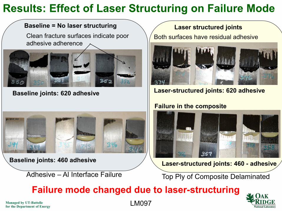
Results: Corrosion - (Single Lap Shear; BondlineThicknesses: 0.25 mm and 0.85mm;Exposure: ASTM B117 Performed by Cosma)
0
500
1000
1500
2000
2500
0.25mmBaseline
0.25mmAblation
0.85mmBaseline
0.85mmAblationLa
p Sh
ear S
tren
gth
(PSI
)
Specimen Preparation
No CorrosionWith Corrosion
1. After corrosion performance was worse for all samples. (No surprise)2. Bondline thickness had minimal effect on the ablated samples.3. The reduction was most dramatic for the thin bondline.4. The reduction in strength was minimal for the thicker bondline.5. For ablated samples, the thick bondline provided far superior corrosion resistance.6. For Non-ablated samples the thicker bondline resulted in higher retained
properties.
LM097

Managed by UT-Battellefor the Department of Energy
Discussion: Can This Approach be Extended to AHSS, Mg Alloys and other Materials? – We Believe So
0
500
1000
1500
2000
2500
3000
Abraded andCleaned
Laser Rastered
Lap
Shea
r Str
engt
h (K
SI)
LM097
10 μm 10 μm
CF Composite to Magnesium –Both Surfaces Laser Rastered -
Adhesive 810
DP980
As Recieved Laser Processed

Managed by UT-Battellefor the Department of Energy
• Scaling to include automated surface preparation and bonding operations.
• Dynamic shear lap testing of joints (different loading rates)
• 2 proposals are currently in evaluation for scaling this technology.
• Next steps: – A follow-on effort is needed to demonstrate the laser-assisted
joining technology of composite and aluminum in a production environment.
Proposed Future Work
LM097Remaining Challenges and Barriers• Scaling to automated robotic control
• Demonstration at production intent scale.
• Assessment of corrosion for in-service parts.
• Demonstration with other material systems.
19

Managed by UT-Battellefor the Department of Energy
Although not required, the project was conducted in collaboration with 3 Industrial Partners
• The Cosma International hoses product engineering and prototype-build facilities in Troy, Michigan and Brampton, Ontario.
– production scale prototype capability: metal stamping, robotic welding, rivet bonding, laser cutting and CMM dimensional inspection equipment.
– metallography & metrology materials characterization laboratory, x-ray, production scale rivet, bonding and welding, laser cutting.
• 3M’s Corporate Materials Research Laboratory is capable of formulating the appropriate adhesive and testing:
– 3M is engaged with external vendors for the raw materials and have access to the appropriate mixing and processing equipment to manufacture adhesives.
• Plasan Carbon Composites (PCC) is the leading Tier I supplier of carbon fiber parts and assemblies in the United States:
– PCC has developed a new high volume, out-of-autoclave process for Class A, structural and semi-structural components for mainstream automotive.
– PCC is the manufacturer and supplier of the hood, roof and liftgate of the new SRT Viper, and the hood and roof (new 2014 Corvette).
– Past parts include: fenders (Corvette Z06); hood, fenders, roof, roof bow, lower rocker moldings and front splitter (2009 Corvette ZRl); rear spoilers, front splitters, and front dive planes (2008 Viper SRT-1 0 ACR); and the splitter, hood assembly and mirror caps (2008 Ford Shelby GT500KR).
LM097

Managed by UT-Battellefor the Department of Energy
Responses to Previous Year Reviewers’ Comments
1. Project need Go-No-Go Decision points. Had one which was met.
2. More realistic joint configurations would be better (i.e. peel). Agreed. This was a proof of concept project. The proposed follow-on will use production intent joint configurations.
3. Presentation needed to be clearer. The presentation style was significantly changed for the 2016 review.
4. More statistical sampling is needed. Data was given for only one coupon. It should have been clarified that a minimum of 6 samples are used for each data point reported.
LM097

Managed by UT-Battellefor the Department of Energy
Summary Significantly increase joint strength. Effective for Al and CFC and indicated applicability to other materials. Demonstrated using epoxy, urethane and acrylic adhesives. Significantly increase the surface roughness of all adherends. Demonstrated to effectively clean contaminates from both adherends. Demonstrated to remove the resin rich layer from the composite. Demonstrated to increase SLS sample strain by 2X Results in a fiber reinforced adhesive/adherend interface in composites. Resulted in a 12-46% improvement in SLS strength. Found that simple rastering is nearly as effective as spot-by-spot. Produced a shift in failure mode from adherend/adhesive interfacial to
adherend failure. Little impact of beam angle was noted. Larger beam sizes seem to be more effective. Thicker bond lines had lower baseline strengths but this was mitigated
by the rastering and by enhanced corrosion mitigation. The increase in strength was not as dramatic for DLS samples as for
SLS, however the 2x increase in energy absorption was still present and the failure mode shifted to occur within the adherends.
LM097

Managed by UT-Battellefor the Department of Energy
Technical Back-Up Slides
LM097
23

Managed by UT-Battellefor the Department of Energy
Publications and Patents1. Sabau, A. S., Chen, J., Jones, J. F., Hackett, A., Jellison, G. D., Daniel, C., Warren, D. and Rehkopf, J. D. (2015) Surface Modification of Carbon Fiber Polymer Composites after Laser Structuring, in Advanced Composites for Aerospace, Marine, and Land Applications II (eds T. Sano and T. S. Srivatsan), John Wiley & Sons, Inc., Hoboken, NJ, USA. doi: 10.1002/9781119093213.ch23
2. J. Chen, A.S. Sabau, J. F. Jones, A. Hackett, G. D. Jellison, C. Daniel, and D. Warren, "Aluminum Surface Texturing by Means of Laser Interference Metallurgy," 2015 TMS Annual Meeting & Exhibition, Proceedings: Light Metals 2015: Aluminium Processing, pp. 427-429, Orlando, FL.
3. Provisional patent application: “Laser Nanostructured Surface Preparation for Joining Dissimilar Materials”
2 Additional Papers are in the works to be published in SAMPE and JOM.
LM097
Do Not distribute outside participant organizations

Managed by UT-Battellefor the Department of Energy
Background: Principle of the laser interference technique
)2/sin(2 αλ
=d
Periodic spacing formed by 2 beam interference
• Wavelength λ• Pulse frequency 10Hz
M
BSM
M
Primary beam
Specimenx
y
MS – mechanical shutterBS – beam splitter
L
L
MS
M – mirrorL – lens
α
Laser spot.Beam 1
Beam 2
Sample mounted on a translational stage controlled by Labview.
• Q-switched Nd:YAG laser system with an harmonic generator enabling the selection of one very sharp wavelengths of 1064, 532, 355, or 266nm.
• Pulse duration 10ns (heating and cooling rates above 1012K/s, frequency = 10Hz
LM097
Managed by UT-Battellefor the Department of Energy
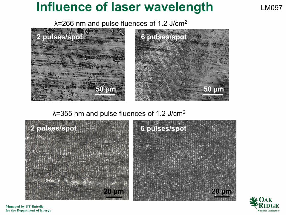
Influence of laser wavelength
50 µm
2 pulses/spot
50 µm
6 pulses/spot
λ=266 nm and pulse fluences of 1.2 J/cm2
λ=355 nm and pulse fluences of 1.2 J/cm2
20 µm
2 pulses/spot 6 pulses/spot
20 µm
LM097