Embed Size (px)
Citation preview

Large Workspace Haptic Devices - A New Actuation ApproachMichael Zinn∗
Department of MechanicalEngineering
University of Wisconsin -Madison
Oussama Khatib†
Robotics LaboratoryDepartment of Computer
ScienceStanford University
Bernard Roth‡
Design DivisionDept. of Mechanical
EngineeringStanford University
J. Kenneth Salisbury§
Robotics LaboratoryDept. of Computer Science
Stanford University
ABSTRACT
Large workspace haptic devices have unique requirements, requir-ing increased power capabilities along with increased safety con-siderations. While there are numerous haptic devices available,large workspace systems are hampered by the limitations of cur-rent actuation technology. To address this, the Distributed Macro-Mini (DM2) actuation method has been applied to the design of alarge workspace haptic device. In this paper, the DM2 method andpresent experimental results which demonstrate its effectiveness.Finally, the control design is presented along with a discussion ofthe unique challenges associated with its robustness.
1 INTRODUCTION
Large workspace haptic devices have a unique set of requirements.These include similar requirements which bound traditionaldesktop devices as well as additional power and force requirementswhich can be very demanding. A number of researchers have de-veloped device performance and requirement guidelines [5, 10, 12].These, in combination with the additional power and safety re-quirements for large workspace devices, can be summarized asfollows:
Large dynamic range force control: To accurately rendera virtual object, a haptic device must have the capability torender forces over a large dynamic range, in both frequency andmagnitude. This requirement can be partitioned as follows:
Torque Vs. Frequency: As shown in [21], as well as else-where, the required force output for many devices, includinghaptic devices, is inversely proportional to frequency (1/ω)while power magnitude is inversely proportional to the squareof frequency (1/ω2). At low frequencies, large forces are re-quired to react DC or slowing changing forces, such as wouldbe expected when pressing into a virtual object. At high fre-quencies, brief instances of high frequency force content arerequired to render stiff surfaces (e.g. during contact transi-tions). While these forces are often short in duration and lowpower, their presence is critical for the accurate rendering ofstiff objects.
High Bandwidth: While required torque and power magni-tude falls off with increased frequency, small amplitude actu-ator torques must be capable of supporting a high bandwidthsystem. This is important to prevent excessive distortion ofthe rendered forces. In the case of admittance devices with agiven closed-loop bandwidth, ωCL, the actuator torque outputmust not introduce phase distortion at frequencies below ωCL.
∗e-mail: [email protected]†e-mail:[email protected]‡e-mail:[email protected]§e-mail:[email protected]
Transparency: An important characteristic of a haptic device is theability to display zero force over a wide frequency range. Introduc-tion of device friction, inertial, or control forces which deviate fromthis ideal reduce the effectiveness of the device. This requirementcan be further broken down by frequency range:
High frequency - Low effective inertia: Regardless of the ar-chitecture of the haptic device (i.e. admittance vs impedance),at high frequencies the transparency is dominated by the ef-fective inertia of the device. The effective inertia is, in turn,affected by the mass properties of the mechanism, the re-flected inertia of the actuation, and location within the deviceworkspace. In the case of admittance devices, the effectiveinertia is dominant above the closed-loop bandwidth of theadmittance controller. For good transparency at high frequen-cies, the physical device must possess low effective inertia.
Low frequency - Low output impedance: At lower frequen-cies, the transparency of a device is affected by its frictionalcharacteristics and, to a lesser extent, by its mass properties.For impedance devices, it is important to keep the effectivefriction forces low. Friction sources include actuation gear-train and joint friction. The low frequency output impedanceof admittance devices is determined by its controller designand implementation in combination with the physical charac-teristics mentioned above.
High power / large force: In addition to those requirements listedabove, a large workspace imposes the additional requirements ofhigh force and power. A major purpose of a large workspace deviceis to allow full arm or body haptic interaction. This type of taskinvolves higher forces than devices which are designed for desktopuse. The larger force, in combination with the larger workspace,implies larger work and power output. It is this requirement, incombination with transparency and force control requirements,which make the design of large workspace haptic devices sochallenging.
Safety: With the increased torque and power capabilities ofa large workspace haptic device comes a new requirement ofsafety. Device safety is dependent on its mechanical, electrical,and software design characteristics. However, the biggest dangerpresent when working in close proximity with a high powerdevice is the potential for large impact loads resulting from thelarge effective inertia. To insure a minimal level of safety, alarge workspace haptic device should be designed to minimize itseffective inertia [20, 21].
Numerous kinesthetic haptic devices have been successfullydesigned, including a number which have had commercial suc-cess [2, 9, 6]. Most devices have been developed for desktopuse, with only a few applicable to large workspace applica-tions [18, 1, 6, 19]. While there has been some limited success indeveloping larger workspace devices, these systems, in general,have been hampered by performance limitations (in the case ofimpedance devices) or safety concerns (in the case of admittance

devices). It is our belief that the limitation of current actuationmethods is the primary obstacle in the development of high-performance large workspace haptic devices. In the followingsections, we will present a new actuator concept which addressesthe requirements enumerated above, allowing for the design of ahaptic device with the ability to render stiff environments overa large workspace. Experimental data shall be presented whichdemonstrates the effectiveness of the new method.
2 DISTRIBUTED MACRO-MINI ACTUATION APPROACH
A new actuation approach, referred to as the distributed macro-mini actuation approach (DM2), has been developed to overcomethe limitations that traditional actuation methods. The uniquecharacteristics of the DM2 approach make it well suited for largeworkspace haptic devices. The overall approach is shown in Fig. 1
The first part of the DM2 actuation approach is to divide thetorque generation into separate low and high-frequency actuatorswhose torque sum in parallel. The partitioning of torques is mo-tivated by the torque vs frequency requirement described in Sec-tion 1. A high-power, high-torque actuator is used to provide thelow frequency torques while a small, fast actuator is used to pro-vide the high frequency torques.
The second part of the DM2 actuation approach is to distributethe low and high-frequency actuators to locations on the devicewhere their effect on device transparency is minimized while theircontribution to force dynamic range is maximized. This is achievedby locating the low-frequency actuator remotely from the actu-ated joint. This is particularly advantageous as the low frequencycomponents of most haptic device force profiles are considerablylarger in magnitude than the high frequency components, and con-sequently require a relatively large actuator. To maintain high-bandwidth, the high-frequency actuator is collocated with the jointto allow undistorted transmission of high frequency torque con-tent. While a number of researchers have explored parallel actu-ation approaches [11, 13, 21] the concept of actuator distributionand its application to the development of haptic devices has notbeen explored. Finally, to provide decoupling between the low andhigh-frequency actuators and to improve the low frequency outputimpedance, a Series Elastic Actuator [15] is utilized for the baseactuator. The SEA actuator incorporates an elastic coupling at itsoutput which, in combination with local torque feedback, decou-ples the low and high-frequency actuators and dramatically reducesthe output impedance of the low-frequency actuator over a broadfrequency range [16].
2.1 DM2 SpecificationsThe effectiveness of the DM2 approach can be evaluated againstthe actuator requirements summarized in Section 1. The followingsections will address each of these requirements in turn.
2.1.1 Torque Vs. FrequencyHigh performance tasks require actuation torque over a broad rangeof frequencies. As shown in Section 1, actuator torque require-ments as a function of frequency are proportional to 1/ω where ωis the operating frequency. The DM2 actuation approach satisfiesthis requirement by combining a large low-frequency actuator witha small high-frequency actuator in parallel.
The low-frequency actuation is designed to have high torque andpower output. Its location off of the manipulator allows for heavier,higher power actuator. Drive-train compliance between the low-frequency actuator and driven joint is not of concern as it is requiredto transmit low frequency torques only. High frequency torques areprovided by small servo motors collocated at the joint. Because thehigh-frequency actuator produces torque intermittently, consistingof only high frequency components, it can be used much closer totheir peak current limits. A simple thermal model of the motor
windings, with sufficient safety margin, is employed in software toprevent overheating of the high-frequency actuators.
The combination of the low and high-frequency actuators pro-vides an output torque profile as a function of frequency that moreclosely matches the 1/ω requirement discussed above. As seen inFigure 2, the two-axis prototype described in Section 4 benefitedsubstantially from the combination of low and high-frequency ac-tuators, producing a torque vs frequency profile which more closelymatches the requirements of Section 1. While the low-frequencySEA actuator output torque falls off rapidly above it closed-loopbandwidth (2.0 Hertz), the addition of the high-frequency motortorque extends the torque envelope to higher frequencies.
Frequency [Hz]
10-1
100
101
102
103
10-2
10-1
100
101
102
Ma
gn
itu
de
[N
-m
]
High-frequency actuator torque output
Low-frequency actuator (SEA) torque output
Combined base and joint actuator torque
high-freq. motor electrical pole, ωj
increasing
required
torque
required torque (~1/ω)
open-loop mode, ωLF
Figure 2: Maximum actuation torque output versus frequency.
2.1.2 High Bandwidth
The primary obstacle to achieving high-bandwidth control is the in-troduction of dynamics between the actuation and driven-link. Ex-amples of these unwanted dynamics include higher frequency actu-ator dynamics, such as the electrical winding dynamics, drive-trainbacklash, friction, and, most troublesome, drive-train compliance.The key to achieving high bandwidth is the elimination of thesecharacteristics.
The DM2’s distributed actuator approach, as well as the properselection of actuator and gearing, eliminates the unwanted dynam-ics described above. The use of low inductance servo motors guar-antees that the electrical time constant is sufficiently high so as toavoid interaction with the control loop. To avoid friction and back-lash, the current embodiment of the DM2 approach employs a cablegear-reducer design possessing very low friction levels and essen-tially zero backlash.
While these characteristics are important, the most essential el-ement of the DM2 approach is the collocation of the mini actuatorwith the manipulator joint. The closed-loop position-bandwidth islimited by the presence of compliance between the actuator anddriven-link. More specifically, the maximum cross-over frequency,ωc, and, by inference the maximum bandwidth, is limited to ap-proximately 1/5th of the first mode frequency, ω j . By collocatingthe high-frequency actuator with the manipulator joint, the drive-train compliance can be minimized. Currently, DM2 implementa-tions have employed a single-stage cable gear reduction with spe-cific stiffening design elements such as dual-cable drive, minimizedfree cable lengths, and rigid drive component supports. A cablegear reduction was chosen to minimize friction and maintain lowoutput impedance. While these features are implementation spe-cific, the objective is to create a high stiffness connection between

AND
To
rq
ue
M
ag
nitu
de
Frequency
D(s)
D(s)
(a)
High Frequency
Actuation
Low Frequency
Actuation
Series Elastic
Actuator
(b)
High Frequency
Actuation
Low Frequency
Actuation
Figure 1: Distributed macro-mini actuation approach (DM2) (a)Partition of torque into low and high frequency (parallel) components (b) Distributedactuation: Large, low-frequency actuators are located at base. Small, high-frequency actuators are located at the joints.
the high-frequency actuator and driven-link and, thereby, achievethe characteristics required for high bandwidth control.
2.1.3 Low Effective Inertia
For a given device, the effective inertia is a function of both thedevice’s inertia as well as the reflected actuator inertia. The DM2’sapproach of placing the low-frequency actuator at the base has thebeneficial effect of reducing both of these.
The reduction in the actuator reflected inertia is due to the de-coupling of the actuator inertia from the device. This decouplingis due, primarily, to the elastic coupling placed between the largelow-frequency actuator and the driven joint. When the compliancebetween the actuator and the link is low, the system acts as a lowpass filter which isolates the actuator’s reflected inertia from the de-vice, reducing the effective inertia perceived by the user and insur-ing good device transparency (at frequencies above the first mode).
2.1.4 Low Output Impedance
The DM2 approach uses the series elastic actuator method(SEA) [15] with the large, low-frequency actuator. Througha combination of mechanical compliance and closed-loop con-trol, the SEA actuator can provide significant reduction in outputimpedance. At frequencies below the closed-loop bandwidth of theSEA controller, ωs, the reflected inertia is reduced by the square ofthe ratio of the natural frequency of the uncontrolled system, ωn, toωs:
τs(s)θa(s)
∣∣∣∣s→0
=ω2
nω2
sIe f f (1)
where Ie f f is the effective inertia of the actuator and gear train. Thisreduction can be quite large. In the case of the two axis prototype
described in Section 4, the actuator and gear train reflected inertiawas reduced by a factor of greater than ten.
Another contributor to output impedance is the inertia, I j , andfriction, τ f , of the high-frequency actuator. As measured at thejoint, the output impedance is given as
τ j(s)θa(s)
= N2j I j +N jτ f (2)
where N j is the high-frequency motor gear reduction. Both the in-ertia and friction component of the output impedance must be min-imized. By design, the high-frequency actuator is selected to havelow inertia, high peak torque and low inductance. The selection of afast ironless core servo motor keeps the overall output impedance ofthe high-frequency actuator small. Because the motors can producehigh peak torque in relation to their size, a high reduction trans-mission in not required, preventing the reflected output impedancefrom being excessively amplified through the gear reduction. Thegear reduction friction is minimized through selection of designs,such as the use of a single stage cable transmission, which havevery low friction characteristics while maintaining high stiffnessbetween the actuator and the manipulator. In the case of the two-axis prototype described in Section 4, the reflected high-frequencyactuator inertia, as measured at the joint, was less than 1/20th ofthe link inertia.
Finally, the device structure can be a contributor to the outputimpedance, particularly for large workspace devices. While locat-ing the large low–frequency actuators at the base of the manipulatorstructure was motivated primarily by the desire to reduce the effec-tive inertia at the input, a consequence of this choice was a signifi-cant decrease in device output impedance at low frequency, as com-pared to a design whose primary power actuators are located on thestructure itself. In the case of the two-axis prototype described in
section 4, the effective inertia for the proximal joint would increaseby a factor of three if the low-frequency actuators were collocatedwith the manipulator joints.
2.1.5 High Power - Large Forces
The distributed characteristic of the DM2 approach is ideal for theapplication of large force and high power. At low frequencies, thesize of the actuation input is virtually unconstrained because it doesnot significantly contribute to the device’s effective inertia. At highfrequencies, the power requirements are modest and can be easilyhandled by the high-frequency actuator collocated with the joint.
2.2 Safety:
As shown in [20], the potential for injury is governed by a device’seffective inertia. The DM2 approach, with its use of a SEA actuatoralong with the distribution of the parallel actuation, has been shownto dramatically reduce the effective inertia for a given device. Thepotential for injury, as measured by a new metric know as the Ma-nipulator Safety Index (MSI), is reduced by more than an order ofmagnitude when compared to conventional actuation [20].
3 DM2 CONTROL APPROACH
The control approach seeks to leverage the characteristics of theparallel actuator structure while dealing with the control challengesassociated with the use of low impedance actuation. At the jointlevel, the DM2 approach is essentially a dual-input single-outputsystem. The redundant actuators provide an additional degree offreedom which can be used in optimizing system performancewhile minimizing actuation effort. For example, in the case oftrajectory tracking, we can use LQR control techniques to obtainan optimum control law based on minimizing control effort andtracking error. The low and high-frequency actuation effort parti-tioning can be accomplished in a similar manner. Recently, dual-actuator control approaches have been developed for applications inthe disk-drive industry [17]. However, these types of control struc-ture are specific to a given task, in this case to trajectory tracking,and do not provide a black-box interface to the actuation similar tothe use of a single actuator. In particular, for applications involv-ing a number of different control modes, such as free-space motionfollowed by contact transitions, or for applications requiring a low-impedance torque source, such as haptics or tele-robotic master de-vices, we desire an actuation control scheme which allows the useof the parallel actuation system as a single torque source.
The overall control approach seeks to exploit the DM2 actu-ation’s unique characteristic to construct a near perfect torquesource. The characteristics of a perfect torque source, consistingof zero output impedance and infinite control bandwidth, are idealfor a haptic device. While a perfect torque source is impossible toachieve, a near perfect torque source, with low output impedancerelative to the driving load and high bandwidth torque capability,offers much of the same advantages.
3.1 Single Joint Control Structure
For most haptic devices, the distributed structure of the DM2 ap-proach will result in a design whereby the low and high-frequencyactuators do not map one-to-one to specific joint torques. Each jointtorque will not be the sum of a single low and high-frequency actua-tor torque but rather, depending of the coupling of the transmissionto joint motion, will be a linear combination of a subset of actua-tor torques. While this coupling exists, it is instructive to examinethe structure and properties of the DM2 control from the view pointof a simple one-degree-of-freedom mechanism. The simple controlstructure of the DM2 approach can be easily extended to a multi-dimensional framework[20]
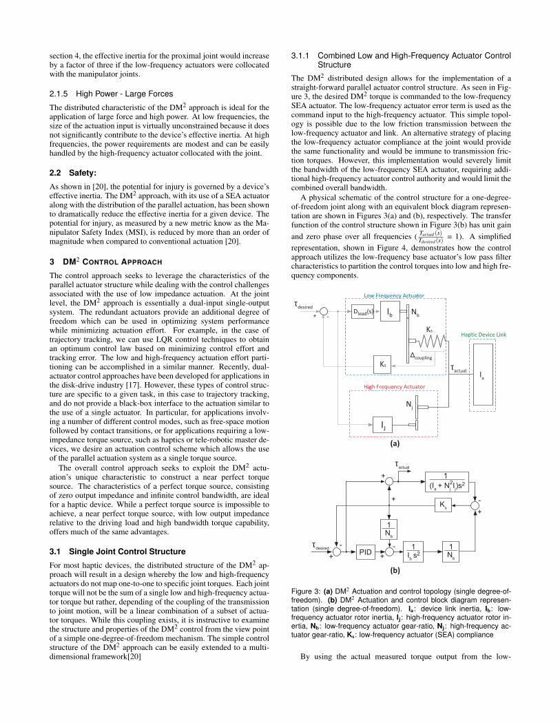
3.1.1 Combined Low and High-Frequency Actuator ControlStructure
The DM2 distributed design allows for the implementation of astraight-forward parallel actuator control structure. As seen in Fig-ure 3, the desired DM2 torque is commanded to the low-frequencySEA actuator. The low-frequency actuator error term is used as thecommand input to the high-frequency actuator. This simple topol-ogy is possible due to the low friction transmission between thelow-frequency actuator and link. An alternative strategy of placingthe low-frequency actuator compliance at the joint would providethe same functionality and would be immune to transmission fric-tion torques. However, this implementation would severely limitthe bandwidth of the low-frequency SEA actuator, requiring addi-tional high-frequency actuator control authority and would limit thecombined overall bandwidth.
A physical schematic of the control structure for a one-degree-of-freedom joint along with an equivalent block diagram represen-tation are shown in Figures 3(a) and (b), respectively. The transferfunction of the control structure shown in Figure 3(b) has unit gainand zero phase over all frequencies ( Tactual(s)
Tdesired(s) = 1). A simplifiedrepresentation, shown in Figure 4, demonstrates how the controlapproach utilizes the low-frequency base actuator’s low pass filtercharacteristics to partition the control torques into low and high fre-quency components.
(Ia
+ N
j
Ij
)s2
1
2
Ks
Ib
s
2
1
Nb
1
+
-
+
+
+
-
Nb
1
+
-
PID
τactual
τdesired
Ia
τactual
Haptic Device Link
Ib
Nb
∆coupling
τdesired
-
Ks
+
Low Frequency Actuator
Nj
IJ
High Frequency Actuator
Dlead
(s)
Ks
(a)
(b)
Figure 3: (a) DM2 Actuation and control topology (single degree-of-freedom). (b) DM2 Actuation and control block diagram represen-tation (single degree-of-freedom). Ia: device link inertia, Ib: low-frequency actuator rotor inertia, Ij: high-frequency actuator rotor in-ertia, Nb: low-frequency actuator gear-ratio, Nj: high-frequency ac-tuator gear-ratio, Ks: low-frequency actuator (SEA) compliance
By using the actual measured torque output from the low-
frequency actuators in combination with the desired torque, weautomatically compensate for the non-ideal behavior of the low-frequency actuators. Assuming that the smaller high-frequencyactuators can produce this torque, the combined torques sum is aperfect realization of the desired torque. The frequency partition-ing can be clearly seen if we rearrange the structure in Figure 4ainto a pure parallel structure, as shown in Figure 4b. As seen inFigure 4b, the low-frequency actuator’s transfer function falls offabove its closed-loop bandwidth, wLFclosed−loop, while the equiv-alent high-frequency actuator’s transfer function approximates adouble lead filter, which adds phase to the combined system abovethe open-loop mode frequency, wLF , and attenuates the DC and lowfrequency components commanded to the high-frequency actuator.
G(s)LF
Frequency
Frequency
1 - G(s)LF
τdesired
+ τactual
+
ω LF closed-loop
(b)
(a)
G(s)LF
G(s)HF
τdesired
+
τactual+
+-
High-frequency actuation
(ωbw
~ 200Hz)
Low-frequency actuation
(ωbw
~ 20Hz)
High-frequency
actuation
Low-frequency
actuation
ω LF
Figure 4: (a) DM2 actuation control structure and (b) frequency re-sponse. G(s)LF: low-frequency actuator closed loop transfer func-tion, G(s)HF: High-frequency actuator transfer function, ωLF: open-loop natural frequency of low-frequency actuator, ωLF−closed−loop:closed-loop bandwidth of low-frequency SEA controller
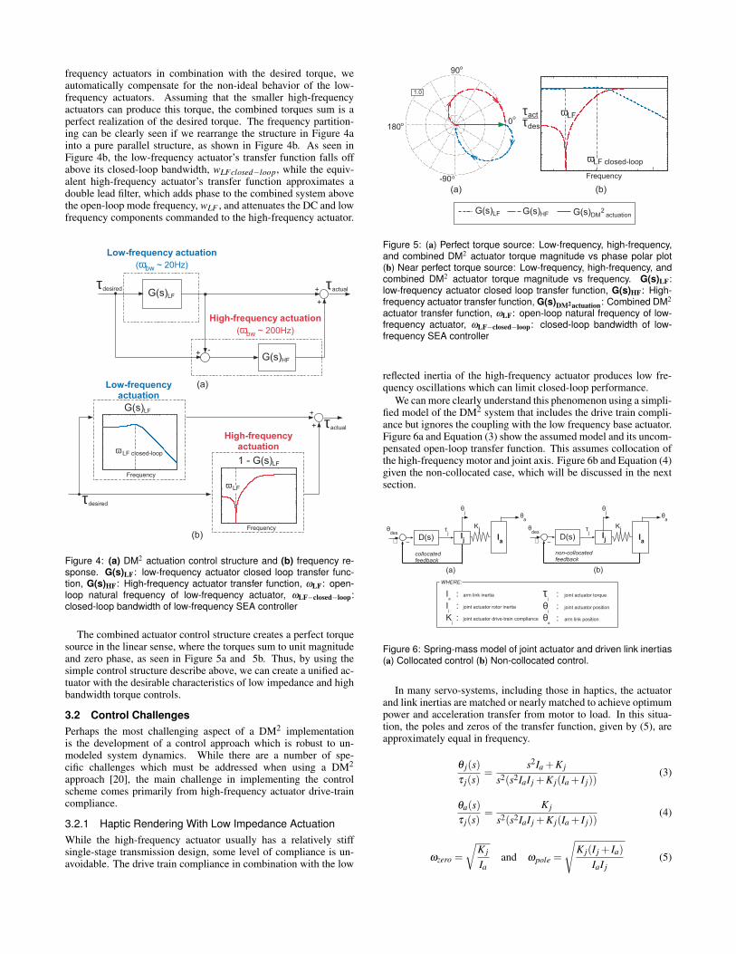
The combined actuator control structure creates a perfect torquesource in the linear sense, where the torques sum to unit magnitudeand zero phase, as seen in Figure 5a and 5b. Thus, by using thesimple control structure describe above, we can create a unified ac-tuator with the desirable characteristics of low impedance and highbandwidth torque controls.
3.2 Control ChallengesPerhaps the most challenging aspect of a DM2 implementationis the development of a control approach which is robust to un-modeled system dynamics. While there are a number of spe-cific challenges which must be addressed when using a DM2
approach [20], the main challenge in implementing the controlscheme comes primarily from high-frequency actuator drive-traincompliance.
3.2.1 Haptic Rendering With Low Impedance ActuationWhile the high-frequency actuator usually has a relatively stiffsingle-stage transmission design, some level of compliance is un-avoidable. The drive train compliance in combination with the low
G(s)HF G(s)
DM actuation
2G(s)LF
(b)
Frequency
τact
τdes
ωLF closed-loop
ωLF
0
o
180o
90o
-90o
(a)
1.0
Figure 5: (a) Perfect torque source: Low-frequency, high-frequency,and combined DM2 actuator torque magnitude vs phase polar plot(b) Near perfect torque source: Low-frequency, high-frequency, andcombined DM2 actuator torque magnitude vs frequency. G(s)LF:low-frequency actuator closed loop transfer function, G(s)HF: High-frequency actuator transfer function, G(s)DM2actuation: Combined DM2
actuator transfer function, ωLF: open-loop natural frequency of low-frequency actuator, ωLF−closed−loop: closed-loop bandwidth of low-frequency SEA controller
reflected inertia of the high-frequency actuator produces low fre-quency oscillations which can limit closed-loop performance.
We can more clearly understand this phenomenon using a simpli-fied model of the DM2 system that includes the drive train compli-ance but ignores the coupling with the low frequency base actuator.Figure 6a and Equation (3) show the assumed model and its uncom-pensated open-loop transfer function. This assumes collocation ofthe high-frequency motor and joint axis. Figure 6b and Equation (4)given the non-collocated case, which will be discussed in the nextsection.
Ia
Kj
θa
θdes
+ −D(s) I
j
τj
(b)
non-collocated
feedback
θj
+ −D(s)
θj
Ij
Ia
τj
Kj
(a)
θa
collocated
feedback
θdes
Ia
: arm link inertia
Ij
: joint actuator rotor inertia
Kj
: joint actuator drive-train compliance
τj
: joint actuator torque
WHERE:
θj
: joint actuator position
θa
: arm link position
Figure 6: Spring-mass model of joint actuator and driven link inertias(a) Collocated control (b) Non-collocated control.
In many servo-systems, including those in haptics, the actuatorand link inertias are matched or nearly matched to achieve optimumpower and acceleration transfer from motor to load. In this situa-tion, the poles and zeros of the transfer function, given by (5), areapproximately equal in frequency.
θ j(s)τ j(s)
=s2Ia +K j
s2(s2IaI j +K j(Ia + I j))(3)
θa(s)τ j(s)
=K j
s2(s2IaI j +K j(Ia + I j))(4)
ωzero =√
K j
Iaand ωpole =
√K j(I j + Ia)
IaI j(5)
However, in a system employing low impedance actuation, thezero’s frequency can be an order of magnitude below the frequencyof the flexible mode pole. This large separation amplifies the flexi-ble mode peak by a factor approximately equal to the ratio of drive-link to motor inertias (see Figure 7).
Collocated Position Control
ωzero
ωpoleInertia Ratio
Ij/I
a
10
2
10.5 0.2 0.1 0.05
where Ieff
= Ij + I
as
2Ieff
1
s2Ij
1
Amplication
Ij + I
a
Ij
Ma
gn
itu
de
(s)j
τ(s)j(n
orm
alize
d)
θ
θj
Ij
Ia
τj
(s)j
τ(s)
jθ
Figure 7: Open-loop transfer function of collocated motor positioncontrol: Amplification of oscillatory pole due to mismatched actuator-link inertia.
This effect severely limits the achievable closed-loop bandwidthand thus performance in general. The effect can be quite puzzlingconsidering that the flexible mode frequency can be very high -an order of magnitude or more above the open-loop crossover fre-quency - and still cause excessive oscillations in the closed-loopresponse. Only when one considers the zero, whose frequency isaffected by the larger driven-link inertia, does it become clear whythe problem exists.
3.2.2 Achieving High Bandwidth ControlThe challenge of implementing high bandwidth control in a DM2
actuated system can be addressed through the combined implemen-tation of prudent mechanical design techniques, which favorablymodify the manipulator’s open-loop dynamics, and control aug-mentation such as filtering and proper actuator-sensor placement.
In addition to mechanical modifications and control signalfiltering[7], a somewhat surprising method to deal with the low fre-quency oscillations associated with low impedance actuation is tochange the control topology from collocated to non-collocated con-trol. We can understand this by examining the open-loop transferfunction of a simple mass-spring model of an actuator-link systemwhich employs non-collocated control. Figure 6b and Equation (4)show the assumed model and its associated transfer function. Atfirst glance, this seems counter intuitive since in most cases the sta-bilizing effect of the zeros associated with collocated control is ben-eficial and allow for more aggressive gains. However, in the case oflarge inertia mismatch, the collocated control zero is the main causeof the problem. A comparison of peaking amplitude (see Figure 8)shows that for large mismatches the non-collocated control may bebetter than a collocated approach. Of course, this doesn’t take intoaccount the tendency of the oscillatory poles to become unstable,and special care must be taken to insure their stability, such as us-ing of a notch filter or a gain stabilizing lag network[4, 3, 8]. Withthis consideration, we can conservatively assume that when usingnon-collocated control we can achieve a cross-over frequency ashigh as 1/5 of the flexible mode frequency. With this assumption,we can see from Figure 8 that when the high-frequency motor in-ertia is much less than the device inertia (I j/Ia < 10) the use ofnon-collocated control allows for a higher closed-loop bandwidththan collocated control. The existing implementations of the DM2
method, described in Section 4 have been implemented using thenon-collocated approach.
4 EXPERIMENTAL RESULTS
To evaluate the DM2 actuation approach, a series of prototypeswere built and evaluated, including a two degree-of-freedom (DOF)
(s)j
τ(s)
a (normalized)θ
Collocated Open
Loop Transfer
Function
(s)j
τ(s)
j (normalized)θ
Non-Collocated
Open Loop
Transfer Function
Frequency
10 0.05
No
rm
alize
d M
agn
itu
de
Inertia Ratio:
Ij/I
aCollocated Control:
Oscillatory Mode Peaking
Non-Collocated Control:
Oscillatory Mode Peaking
DM
(BASE/JOINT
ACTUATOR)
2
Figure 8: Variation of peaking amplitude for collocated and non-collocated position control for varying motor to load inertia ratios,I j/Ia
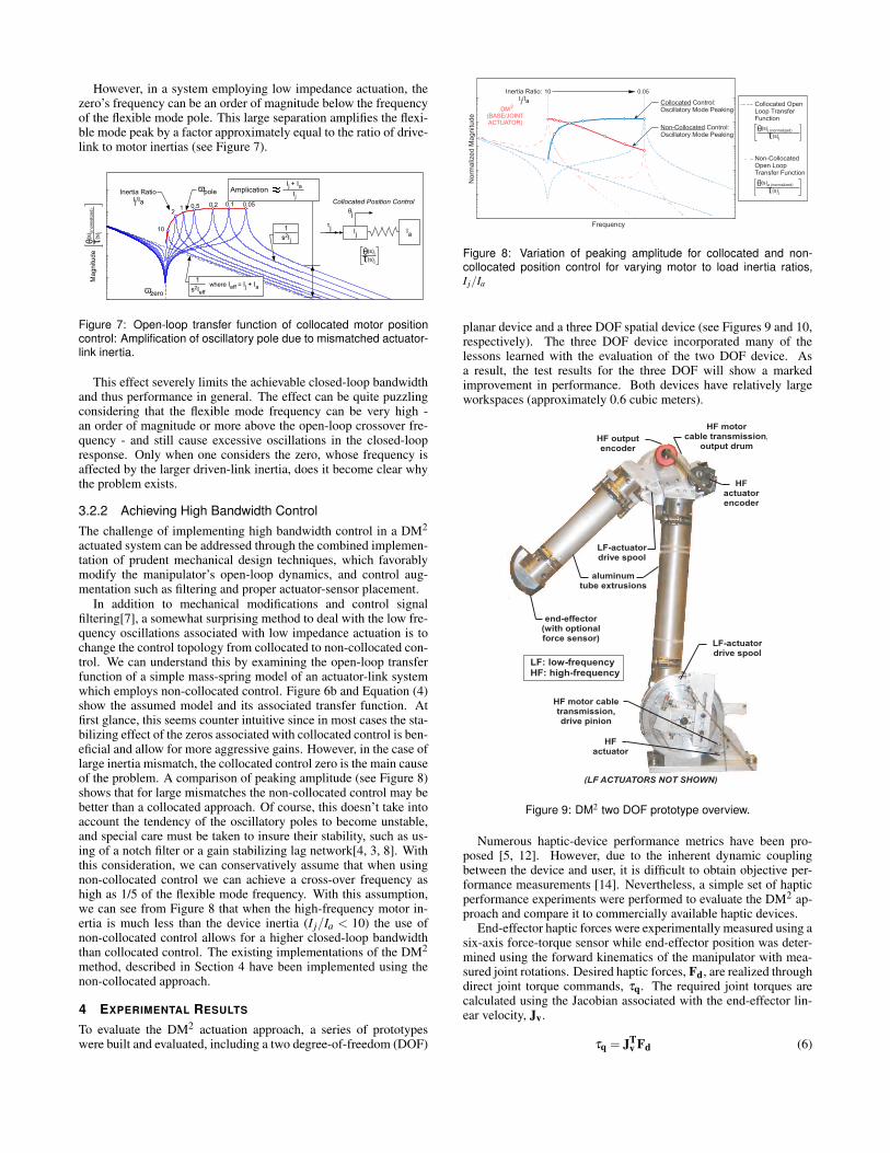
planar device and a three DOF spatial device (see Figures 9 and 10,respectively). The three DOF device incorporated many of thelessons learned with the evaluation of the two DOF device. Asa result, the test results for the three DOF will show a markedimprovement in performance. Both devices have relatively largeworkspaces (approximately 0.6 cubic meters).
HF
actuator
HF
actuator
encoder
HF output
encoder
HF motor cable
transmission,
drive pinion
HF motor
cable transmission,
output drum
aluminum
tube extrusions
end-effector
(with optional
force sensor)
LF-actuator
drive spool
LF-actuator
drive spool
(LF ACTUATORS NOT SHOWN)
LF: low-frequency
HF: high-frequency
Figure 9: DM2 two DOF prototype overview.
Numerous haptic-device performance metrics have been pro-posed [5, 12]. However, due to the inherent dynamic couplingbetween the device and user, it is difficult to obtain objective per-formance measurements [14]. Nevertheless, a simple set of hapticperformance experiments were performed to evaluate the DM2 ap-proach and compare it to commercially available haptic devices.
End-effector haptic forces were experimentally measured using asix-axis force-torque sensor while end-effector position was deter-mined using the forward kinematics of the manipulator with mea-sured joint rotations. Desired haptic forces, Fd, are realized throughdirect joint torque commands, τq. The required joint torques arecalculated using the Jacobian associated with the end-effector lin-ear velocity, Jv.
τq = JTv Fd (6)

HF motor
cable transmission,
output drum
LF-actuator
drive spool
HF
actuator
encoder
HF
actuator and
encoder
device
input
(LF ACTUATORS NOT
SHOWN) LF: low-frequency
HF: high-frequency
Figure 10: DM2 three DOF prototype overview.
The required actuator torques are a function of the joint torquesand drive-train kinematics. The calculation of the required actuatortorque and subsequent control was implemented using a straight-forward control structure [ref ZINN].
The first set of haptics performance experiments measured themaximum obtainable virtual wall stiffness. In each experiment, thevirtual wall stiffness was increased until the device was no longerstable. As discussed earlier, the dynamic coupling between the de-vice and the user makes it difficult to precisely define stability. Forthe purposes of this experiment, stability is defined as the pointwhere the device requires noticeable effort on the part of the op-erator to prevent unwanted end-effector oscillations. Test resultsusing both the two and three degree-of-freedom devices is shownin Figure 11. The plots in Figure 11 show measured end-effectorforce as a function of end-effector displacement perpendicular tothe haptic virtual wall. The results plot the forces and displacementover approximately ten user interactions with the virtual wall.
10
20
40
60
Me
asu
re
d F
orce
[N
]
30
50
0
0 1 2 3
Virtual Wall Penetration [mm]
K = 12.8 kN/m
two DOF DM2
prototype
K = 57 kN/m
three DOF DM2
prototype
Figure 11: Maximum achievable virtual wall stiffness - measuredend-effector force and displacement.
As seen in Figure 11, the maximum obtainable stiffness forthe DM2 two degree-of-freedom prototype was approximately 12kN/m while the stiffness of the three degree-of-freedom device wasin excess of 55 kN/m. In comparison to commercially availableimpedance-type haptic devices, the DM2 actuated prototype hasequal or greater stiffness (see Figure 12). In addition, the workspacevolume of the two and three degree-of-freedom DM2 prototypesare more than five times larger than the other devices listed in Fig-
Delta OmegaTwo DOF
DM2
Force
Dimension
SensableNot
Applicable
14.5 14.5 3.5 12.0
Device
Manufacturer
Stiffness
[N/mm]
20 12 1.4 30
Max
Continuous Force [N]
0.11 0.02 0.02 0.6 [a]
Workspace
Volume [ m3
]
Force
Dimension
Specification
[a] workspace volume based on two-dof testbed workspace with a hypothetical vertical third axis added
Phantom
Premium
1.5
Not
Applicable
57.0
60
0.6
Three DOF
DM2
Figure 12: Haptic Device Comparison.
ure 121. Finally, the measured maximum continuous force of thetwo DOF DM2 device is 50 percent larger than the commercialdevices listed while the three DOF DM2 device is more than 300percent larger.
These results are summarized in Figures 13 and 14. As seenin Figures 13 and 14, the DM2 implementation has increased theworkspace, virtual stiffness, and maximum continuous force avail-able as compared to the devices listed. The combination of all threecharacteristics are necessary for a successful large workspace hap-tic device implementation.
10
20
30
40
50
60
0
Ma
x. V
irtu
al S
tiffn
ess [N
/m
m]
Max. Continuous Force [N]
10 20 30 40 50 600 70
Phantom 1.5
Omega
Delta
DM2
three DOF
DM2
two DOF
Figure 13: Maximum stiffness vs maximum continuous force (com-parison of DM2 prototypes to various commercial devices.
In addition to high stiffness and force output, haptic devices re-quire low output impedance, as measured at the end-effector, to cre-ate the sense of transparency necessary to simulate zero force. Im-plementation of the DM2 control structure described in Section 3effectively removes the remaining low-frequency actuator frictionand inertial forces not already attenuated by the low-frequency ac-tuator SEA controller. To demonstrate this, a simple end-effectoreffective-friction experiment was carried out using the two-degree-of-freedom prototype. In the experiment, the end-effector wasmoved along a virtual line2 and the forces at the end-effector were
1The workspace volume for the two DOF device in Figure 12 is basedon the measured workspace area of the two-axis prototype with the additionof a hypothetical third axis, which is vertical and perpendicular to the twoaxes, and intersecting the center of the shoulder joint (joint 1) of the existingtest-bed.
2Using hybrid control, where the end-effector was controlled to maintain
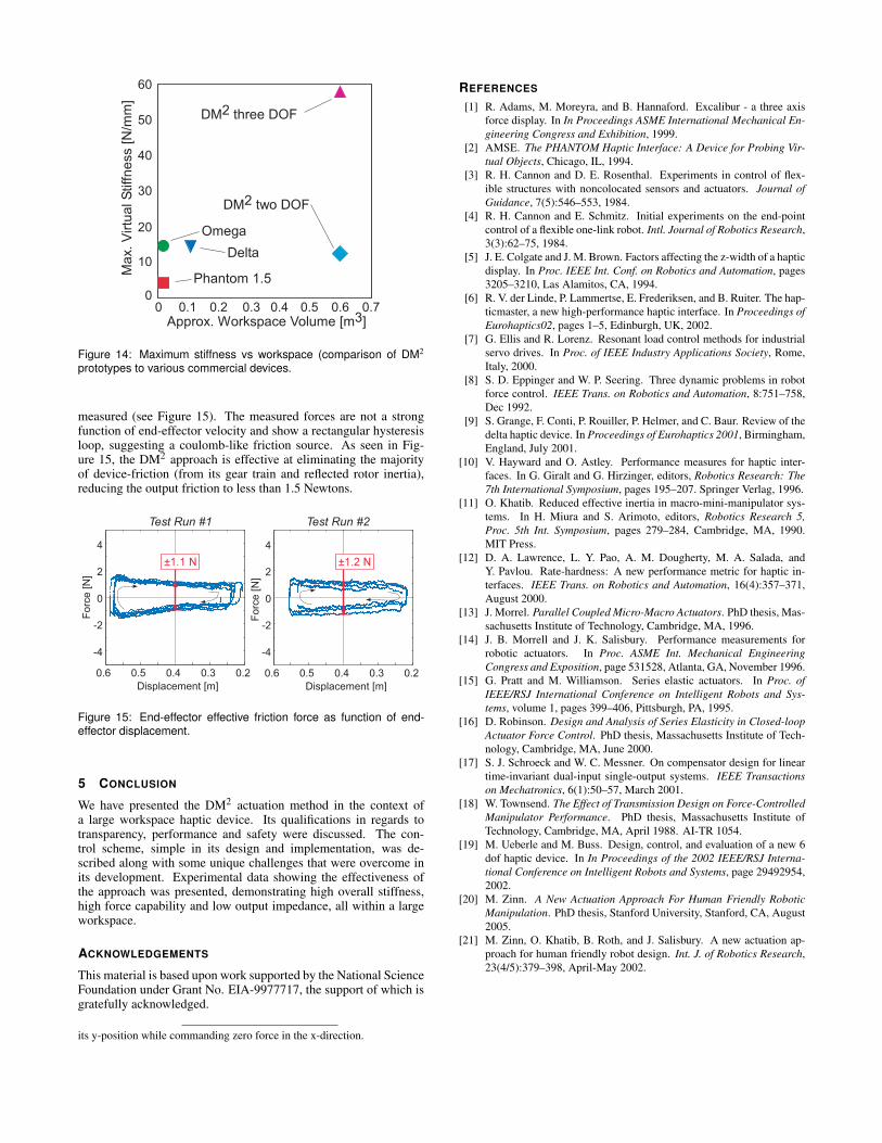
Approx. Workspace Volume [m3
]
0.1 0.2 0.3 0.4 0.5 0.60 0.7
10
20
30
40
50
60
0
Ma
x. V
irtu
al S
tiffn
ess [N
/m
m]
Phantom 1.5
Omega
Delta
DM2
three DOF
DM2
two DOF
Figure 14: Maximum stiffness vs workspace (comparison of DM2
prototypes to various commercial devices.
measured (see Figure 15). The measured forces are not a strongfunction of end-effector velocity and show a rectangular hysteresisloop, suggesting a coulomb-like friction source. As seen in Fig-ure 15, the DM2 approach is effective at eliminating the majorityof device-friction (from its gear train and reflected rotor inertia),reducing the output friction to less than 1.5 Newtons.
Test Run #1
Displacement [m]
0.5 0.4 0.3 0.2
-4
-2
0
2
4
Fo
rce
[N
]
0.6
Displacement [m]
0.5 0.4 0.3 0.2
-4
-2
0
2
4
Fo
rce
[N
]
0.6
Test Run #2
Figure 15: End-effector effective friction force as function of end-effector displacement.
5 CONCLUSION
We have presented the DM2 actuation method in the context ofa large workspace haptic device. Its qualifications in regards totransparency, performance and safety were discussed. The con-trol scheme, simple in its design and implementation, was de-scribed along with some unique challenges that were overcome inits development. Experimental data showing the effectiveness ofthe approach was presented, demonstrating high overall stiffness,high force capability and low output impedance, all within a largeworkspace.
ACKNOWLEDGEMENTS
This material is based upon work supported by the National ScienceFoundation under Grant No. EIA-9977717, the support of which isgratefully acknowledged.
its y-position while commanding zero force in the x-direction.
REFERENCES
[1] R. Adams, M. Moreyra, and B. Hannaford. Excalibur - a three axisforce display. In In Proceedings ASME International Mechanical En-gineering Congress and Exhibition, 1999.
[2] AMSE. The PHANTOM Haptic Interface: A Device for Probing Vir-tual Objects, Chicago, IL, 1994.
[3] R. H. Cannon and D. E. Rosenthal. Experiments in control of flex-ible structures with noncolocated sensors and actuators. Journal ofGuidance, 7(5):546–553, 1984.
[4] R. H. Cannon and E. Schmitz. Initial experiments on the end-pointcontrol of a flexible one-link robot. Intl. Journal of Robotics Research,3(3):62–75, 1984.
[5] J. E. Colgate and J. M. Brown. Factors affecting the z-width of a hapticdisplay. In Proc. IEEE Int. Conf. on Robotics and Automation, pages3205–3210, Las Alamitos, CA, 1994.
[6] R. V. der Linde, P. Lammertse, E. Frederiksen, and B. Ruiter. The hap-ticmaster, a new high-performance haptic interface. In Proceedings ofEurohaptics02, pages 1–5, Edinburgh, UK, 2002.
[7] G. Ellis and R. Lorenz. Resonant load control methods for industrialservo drives. In Proc. of IEEE Industry Applications Society, Rome,Italy, 2000.
[8] S. D. Eppinger and W. P. Seering. Three dynamic problems in robotforce control. IEEE Trans. on Robotics and Automation, 8:751–758,Dec 1992.
[9] S. Grange, F. Conti, P. Rouiller, P. Helmer, and C. Baur. Review of thedelta haptic device. In Proceedings of Eurohaptics 2001, Birmingham,England, July 2001.
[10] V. Hayward and O. Astley. Performance measures for haptic inter-faces. In G. Giralt and G. Hirzinger, editors, Robotics Research: The7th International Symposium, pages 195–207. Springer Verlag, 1996.
[11] O. Khatib. Reduced effective inertia in macro-mini-manipulator sys-tems. In H. Miura and S. Arimoto, editors, Robotics Research 5,Proc. 5th Int. Symposium, pages 279–284, Cambridge, MA, 1990.MIT Press.
[12] D. A. Lawrence, L. Y. Pao, A. M. Dougherty, M. A. Salada, andY. Pavlou. Rate-hardness: A new performance metric for haptic in-terfaces. IEEE Trans. on Robotics and Automation, 16(4):357–371,August 2000.
[13] J. Morrel. Parallel Coupled Micro-Macro Actuators. PhD thesis, Mas-sachusetts Institute of Technology, Cambridge, MA, 1996.
[14] J. B. Morrell and J. K. Salisbury. Performance measurements forrobotic actuators. In Proc. ASME Int. Mechanical EngineeringCongress and Exposition, page 531528, Atlanta, GA, November 1996.
[15] G. Pratt and M. Williamson. Series elastic actuators. In Proc. ofIEEE/RSJ International Conference on Intelligent Robots and Sys-tems, volume 1, pages 399–406, Pittsburgh, PA, 1995.
[16] D. Robinson. Design and Analysis of Series Elasticity in Closed-loopActuator Force Control. PhD thesis, Massachusetts Institute of Tech-nology, Cambridge, MA, June 2000.
[17] S. J. Schroeck and W. C. Messner. On compensator design for lineartime-invariant dual-input single-output systems. IEEE Transactionson Mechatronics, 6(1):50–57, March 2001.
[18] W. Townsend. The Effect of Transmission Design on Force-ControlledManipulator Performance. PhD thesis, Massachusetts Institute ofTechnology, Cambridge, MA, April 1988. AI-TR 1054.
[19] M. Ueberle and M. Buss. Design, control, and evaluation of a new 6dof haptic device. In In Proceedings of the 2002 IEEE/RSJ Interna-tional Conference on Intelligent Robots and Systems, page 29492954,2002.
[20] M. Zinn. A New Actuation Approach For Human Friendly RoboticManipulation. PhD thesis, Stanford University, Stanford, CA, August2005.
[21] M. Zinn, O. Khatib, B. Roth, and J. Salisbury. A new actuation ap-proach for human friendly robot design. Int. J. of Robotics Research,23(4/5):379–398, April-May 2002.


![[DEMO] Comprehensive Workspace Calibration for …imd.naist.jp/imdweb/pub/eck_ismar14/paper.pdfTitle [DEMO] Comprehensive Workspace Calibration for Visuo-Haptic Augmented Reality Author](https://img.dokumen.tips/doc/110x75/5edf3438ad6a402d666a8dd1/demo-comprehensive-workspace-calibration-for-imdnaistjpimdwebpubeckismar14paperpdf.jpg)