Embed Size (px)
Citation preview

NWIndian Fisheries
CommissionTimber Fish
& Wildlife
TFW Monitoring Program
METHOD MANUAL
for the
LARGE WOODY DEBRIS SURVEY
TFW-AM9-99-004
June 1999
by:
Dave Schuett-HamesAllen E. Pleus
Jim WardMartin FoxJeff Light

TFW Monitoring Program Manual - June 1999
Large Woody Debris Survey
Schuett-Hames, D., A.E. Pleus, J.Ward, M. Fox, and J. Light. 1999. TFW Monitoring Program methodmanual for the large woody debris survey. Prepared for the Washington State Dept. of Natural Resources underthe Timber, Fish, and Wildlife Agreement. TFW-AM9-99-004. DNR #106. March.
TFW Monitoring ProgramNorthwest Indian Fisheries Commission
6730 Martin Way E.Olympia, WA 98516
Ph: (360)438-1180Fax: (360)753-8659
Internet:http://www.nwifc.wa.gov
Washington Dept. of Natural ResourcesForest Practices Division: CMER Documents
P.O. Box 47014Olympia, WA 98504-7014
Ph: (360)902-1400
Abstract
The TFW Monitoring Program method manual for the Large Woody Debris (LWD)Survey provides a standard method for assessing and monitoring the quantity and qual-ity of large woody debris. The LWD Survey has two methods for measuring the amountof large woody debris at the TFW stream segment scale. The relatively quick Level 1method quantifies the number of pieces in each of several size class categories and bybankfull channel zone. The Level 2 method collects more detailed information on indi-vidual pieces including piece count, volume by bankfull channel zone, whether it isdeciduous or conifer, and stability. In addition, LWD jam information is collected forboth Level 1 and Level 2 Surveys. The Jam method collects information on jam andpiece count, number of jams by bankfull channel zone, and number of pieces per jam ineach of several size class categories. Association with a Reference Point Survey pro-vides information on piece and jam distribution. Optional key piece information can becollected for the Level 1 and Jam methods and is calculated in the database for Level 2pieces. TFW data management services provides basic analysis of LWD data at 100meter (except Level 1) and stream segment scales. Standard calculations include thenumber of pieces and jams per channel width and kilometer.
This introduction section describes the purpose of the LWD Survey, reviews scientificbackground information, and describes the cooperator services provided by the TFWMonitoring Program. Following the introduction, sections are presented in order of sur-vey application including: study design, pre-survey preparation, stream discharge mea-surement, survey method, post-survey documentation, data management, and references.An extensive appendix is also provided that includes: copy masters of field forms; ex-amples of completed field forms; a field criteria and code sheet; a standard field andvehicle gear checklist; and data management examples.

Large Woody Debris Survey
TFW Monitoring Program Manual - June 1999
The Authors
Dave Schuett-Hames is the TFW MonitoringProgram Coordinator/Biologist at the NorthwestIndian Fisheries Commission. He received a B.S.degree in biology (1976) and an M.E.S. (1996)from The Evergreen State College. He worked for12 years as a fish habitat biologist for the Lummiand the Squaxin Island Tribes. He joined the pro-gram in 1992. E-mail: [email protected]
Allen E. Pleus is the Lead Training and QualityAssurance Biologist for the TFW Monitoring Pro-gram at the Northwest Indian Fisheries Commis-sion. He received a B.A. degree in communica-tions (1985) and an M.E.S. (Master’s degree inEnvironmental Studies, 1995) from The EvergreenState College. He began working for the programin 1991. E-mail: [email protected]
Jim Ward is a Slope Stability Geologist for theWeyerhaeuser Timber Company. Mailing address:Box 420, Centralia, WA 98513.E-mail: [email protected]
Martin Fox is a Fisheries Biologist for theMuckleshoot Indian Tribe Fisheries Department.He received a B.S. degree in Fisheries Biology fromthe University of Washington in 1986. Mailingaddress: 39015 172nd Ave SE, Auburn, WA98092. E-mail: [email protected]
Jeff Light is a Forest Hydrologist for the PlumCreek Timber Company - Cascade Region. Hereceived a B.S. degree in Biology from the Uni-versity of Colorado and a M.S. degree in Fisheriesfrom the University of Washington. He has workedfor TFW since 1987 and as a co-chair on the Moni-toring Advisory Group since 1992. Mailing ad-dress: 999 3rd Ave. Suite 2300, Seattle, WA 98104.E-mail: [email protected]
Copying of the Method Manual
All TFW Monitoring Program method manuals arepublic documents. No permission is required tocopy any part. The only requirement is that theybe properly cited. Copies of the methods manualsare available from the TFW Monitoring Programat the Northwest Indian Fisheries Commission orfrom the Washington Dept. of Natural Resources.
Acknowledgements
The development of this document was funded bythe Timber-Fish-Wildlife (TFW) CooperativeMonitoring, Evaluation, and Research (CMER)committee twith funds provided by the Washing-ton Department of Natural Resources. Specialthanks to Jeff Grizzel for reviewing the draftmanual. Thanks to Tim Hyatt for assistance withthe decay class system, and Robert Beschta andRobert Bilby for assistance with the channelorientation system. TFW Monitoring Program(TFW-MP) staff members Amy Morgan, MylaMcGowan, and Devin Smith contributed a greatmany hours collecting information, reviewing andediting drafts, and helping with production.Northwest Indian Fisheries Commission (NWIFC)staff members including Tony Meyer, SheilaMcCloud, and Debbie Preston have providedvaluable proofing, layout, and productionassistance. Finally, thanks to the TFW MonitoringAdvisory Group members including RandyMcIntosh and Jeff Light (Co-chairs) for theirsupport and guidance.
Manual cover, method illustrations, and layout byAllen Pleus unless otherwise noted.

TFW Monitoring Program Manual - June 1999
Large Woody Debris Survey
1 Introduction1.1 Purpose1.2 Background1.2.1 Biological Role of Large Woody Debris1.2.2 Effects of Large Woody Debris on Channel Morphology1.2.3 Distribution of Large Woody Debris Within Watersheds and Stream Segments1.3 Cooperator Services
2 Study Design2.1 Identifying Monitoring Segments2.2 Survey Method Options2.3 Channel Length and Width and the TFW Referenece Point Survey2.4 Timing of Surveys2.5 Survey Additional Parameters and Modification Options2.6 Pre-Season Crew Training and Quality Assurance Review
3 Pre-Survey Preparation3.1 Survey Equipment3.2 Survey Materials3.2.1 LWD “HEADER INFORMATION” Form 4.03.2.2 LWD “FIELD DATA” Forms 4.1, 4.2, and 4.33.2.3 LWD Criteria and Code Field Sheet
4 Stream Discharge Measurement
5 Large Woody Debris Survey Methods5.1 Large Woody Debris and Channel Zone Identification5.1.1 LWD Log Identification5.1.2 LWD Rootwad Identification5.1.3 LWD Jam Identification5.1.4 Channel Zone Identification5.2 LWD Level 1 Survey Procedure5.2.1 Level 1 Core Data Collection5.2.2 Level 1 Supplemental Data Collection5.3 LWD Level 2 Survey Procedure5.3.1 Level 2 Core Data Collection5.3.2 Level 2 Supplemental Data Collection5.4 LWD Jam Survey Procedure5.4.1 Jam Core Data Collection5.4.2 Jam Supplemental Data Collection
6 Post-Survey Documentation6.1 Finalizing Forms 4.0, 4.1, 4.2, and 4.36.2 Error Checking
. . . . . . . . . . . . . . . . . . . . . . . . . . . . . . . . . . . . . . . . . . . . . . . . . . . . . . . . . . . . . . . . 1 . . . . . . . . . . . . . . . . . . . . . . . . . . . . . . . . . . . . . . . . . . . . . . . . . . . . . . . . . . . . . . . . . . . 1
. . . . . . . . . . .. . . . . . . . . . . . . . . . . . . . . . . . . . . . . . . . . . . . . . . . . . . . . . . . . . . . . . 1 . . . . . . . . . . . . . . . . . . . . . . . . . . . . . . . . . . . . . . . 2
. . . . . . . . . . . . . . . . . . . . . . . . . . 2 . . . . . . . . . . 2
. . . . . . . . . . . . . . . . . . . . . . . . . . . . . . . . . . . . . . . . . . . . . . . . . . . . . . . . . . . 2
. . . . . . . . . . . . . . . . . . . . . . . . . . . . . . . . . . . . . . . . . . . . . . . . . . . . . . . . . . . . . . . . 3 . . . . . . . . . . . . . . . . . . . . . . . . . . . . . . . . . . . . . . . . . . . . . . . . . . 3
. . . . . . . . . . . . . . . . . . . . . . . . . . . . . . . . . . . . . . . . . . . . . . . . . . . . . . . . . 3 . . . . . . . . . . . . . . . . . . . . . . . . . 4
. . . . . . . . . . . . . . . . . . . . . . . . . . . . . . . . . . . . . . . . . . . . . . . . . . . . . . . . . . . . . 4. . . . . . . . . . . . . . . . . . . . . . . . . . . . . . . . 4 . . . . . . . . . . . . . . . . . . . . . . . . . . . . . . . 5
. . . . . . . . . . . . . . . . . . . . . . . . . . . . . . . . . . . . . . . . . . . . . . . . . . . . . . . . 6. . . . . . . . . . . . . . . . . . . . . . . . . . . . . . . . . . . . . . . . . . . . . . . . . . . . . . . . . . . . 6
. . . . . . . . . . . . . . . . . . . . . . . . . . . . . . . . . . . . . . . . . . . . . . . . . . . . . . . . . . . . . 6. . . . . . . . . . . . . . . . . . . . . . . . . . . . . . . . . 6
. . . . . . . . . . . . . . . . . . . . . . . . . . . . . . . . . 8. . . . . . . . . . . . . . . . . . . . . . . . . . . . . . . . . . . . . . . . . . 8
. . . . . . . . . . . . . . . . . . . . . . . . . . . . . . . . . . . . . . . . . . . . . . . . 9
. . . . . . . . . . . . . . . . . . . . . . . . . . . . . . . . . . . . . . . . . . . . 10 . . . . . . . . . . . . . . . . . . . . . . . . . . . . . . . . . . 10
. . . . . . . . . . . . . . . . . . . . . . . . . . . . . . . . . . . . . . . . . . . . . . . . . 10. . . . . . . . . . . . . . . . . . . . . . . . . . . . . . . . . . . . . . . . . . . . . . 12
. . . . . . . . . . . . . . . . . . . . . . . . . . . . . . . . . . . . . . . . . . . . . . . . . . 13. . . . . . . . . . . . . . . . . . . . . . . . . . . . . . . . . . . . . . . . . . . . . . . 15
. . . . . . . . . . . . . . . . . . . . . . . . . . . . . . . . . . . . . . . . . . . . . . . . . . 16. . . . . . . . . . . . . . . . . . . . . . . . . . . . . . . . . . . . . . . . . . . . . . 16
. . . . . . . . . . . . . . . . . . . . . . . . . . . . . . . . . . . . . . . 16 . . . . . . . . . . . . . . . . . . . . . . . . . . . . . . . . . . . . . . . . . . . . . . . . . . 18
. . . . . . . . . . . . . . . . . . . . . . . . . . . . . . . . . . . . . . . . . . . . . . 18 . . . . . . . . . . . . . . . . . . . . . . . . . . . . . . . . . . . . . . . 20
. . . . . . . . . . . . . . . . . . . . . . . . . . . . . . . . . . . . . . . . . . . . . . . . . . . . . 23. . . . . . . . . . . . . . . . . . . . . . . . . . . . . . . . . . . . . . . . . . . . . . . . . 24
. . . . . . . . . . . . . . . . . . . . . . . . . . . . . . . . . . . . . . . . . . 25
. . . . . . . . . . . . . . . . . . . . . . . . . . . . . . . . . . . . . . . . . . . . . . . . . . . 27. . . . . . . . . . . . . . . . . . . . . . . . . . . . . . . . . . . . . . . . . . . . . 27
. . . . . . . . . . . . . . . . . . . . . . . . . . . . . . . . . . . . . . . . . . . . . . . . . . . . . . . . . . . . . . 28
Contents

Large Woody Debris Survey
TFW Monitoring Program Manual - June 1999
7 Data Management7.1 Data Preparation7.2 Data Processing, Products and Archiving7.3 Data Analysis7.3.1 Level 1 Large Woody Debris Survey Report7.3.2 Level 2 Large Woody Debris Survey Report7.3.3 Data Summary by Reference Point Report
8 References
9 AppendixesAppendix A: Form 4.0, 4.1, 4.2, and 4.3 Copy MastersAppendix B: Completed Examples of Forms 4.0, 4.1, 4.2, and 4.3Appendix C: LWD Criteria and Code Field Sheet Copy MasterAppendix D: Standard Field and Vehicle Gear Checklist Copy MasterAppendix E: Data Management Examples
. . . . . . . . . . . . . . . . . . . . . . . . . . . . . . . . . . . . . . . . . . . . . . . . . . . . . . . . . . . 29. . . . . . . . . . . . . . . . . . . . . . . . . . . . . . . . . . . . . . . . . . . . . . . . . . . . . . . . . . . . . 29
. . . . . . . . . . . . . . . . . . . . . . . . . . . . . . . . . . . . . . . . . . . 29 . . . . . . . . . . . . . . . . . . . . . . . . . . . . . . . . . . . . . . . . . . . . . . . . . . . . . . . . . . . . . . . 30
. . . . . . . . . . . . . . . . . . . . . . . . . . . . . . . . . . . 30 . . . . . . . . . . . . . . . . . . . . . . . . . . . . . . . . . . . 30
. . . . . . . . . . . . . . . . . . . . . . . . . . . . . . 31
. . . . . . . . . . . . . . . . . . . . . . . . . . . . . . . . . . . . . . . . . . . . . . . . . . . . . . . . . . . . . . . 32
. . . . . . . . . . . . . . . . . . . . . . . . . . . . . . . . . . . . . . . . . . . . . . . . . . . . . . . . . . . . . . . 34
Contents (cont.)

Large Woody Debris Survey
1
TFW Monitoring Program Manual - June 1999
Large Woody Debris Survey
1. Introduction
The TFW Monitoring Program method manual for theLarge Woody Debris (LWD) Survey provides a stan-dard method for assessing and monitoring the quan-tity and quality of large woody debris. The LWD Sur-vey has two methods for measuring the amount of largewoody debris at the TFW stream segment scale. Therelatively quick Level 1 method quantifies the num-ber of pieces in each of several size class categoriesand by bankfull channel zone. The Level 2 methodcollects more detailed information on individual piecesincluding piece count, volume by bankfull channelzone, whether it is deciduous or conifer, and stability.In addition, LWD jam information is collected for bothLevel 1 and Level 2 Surveys. The Jam method col-lects information on jam and piece count, number ofjams by bankfull channel zone, and number of piecesper jam in each of several size class categories. Asso-ciation with a Reference Point Survey provides infor-mation on piece and jam distribution. Optional keypiece information can be collected for the Level 1 andJam methods and is calculated in the database for Level2 pieces. TFW data management services providesbasic analysis of LWD data at 100 meter (exceptLevel 1) and stream segment scales. Standard calcu-lations include the number of pieces and jams per chan-nel width and kilometer.
This introduction section describes the purpose of theLWD Survey, reviews scientific background informa-tion, and describes the cooperator services providedby the TFW Monitoring Program. Following the in-troduction, sections are presented in order of surveyapplication including: study design, pre-survey prepa-ration, stream discharge measurement, survey method,post-survey documentation, data management, and ref-
erences. An extensive appendix is also provided thatincludes: copy masters of field forms; examples ofcompleted field forms; a field criteria and code sheet;a standard field and vehicle gear checklist; and datamanagement examples.
1.1 Purpose
The Timber-Fish-Wildlife Monitoring Program (TFW-MP) provides standard methods for monitoringchanges and trends in stream channel morphology andhabitat characteristics. The Large Woody Debris(LWD) Survey method has been approved by TFW’sCooperative Monitoring, Evaluation and ResearchCommittee (CMER) and is accepted as a standardmethod for monitoring on forest lands in Washingtonstate by tribal governments, state natural resource agen-cies, timber companies, environmental organizations,and others. The purpose of the Large Woody DebrisSurvey method is to:
1.2 Background
This section provides a review of the scientific litera-ture used as the basis for the LWD Survey. Backgroundinformation includes the biological role of large woody
1. Provide a means of accurately documenting the current abundance, characteristics, and function of large woody debris in stream channels.2. Provide a repeatable methodology that can be used to monitor changes in the status of large woody debris over time.3. Provide information on the abundance and characteristics of large woody debris that is suitable for use in the Watershed Analysis Assessment procedure.4. Improve knowledge of the distribution, characteristics, and function of large woody debris in Pacific Northwest streams.

Large Woody Debris Survey
2
TFW Monitoring Program Manual - June 1999
debris, the effects of large woody debris on channelmorphology, and the distribution of large woody debriswithin watersheds and stream segments.
1.2.1 Biological Role of Large Woody Debris
Large woody debris plays an important biological rolein Pacific Northwest streams, creating and enhancingfish habitat through increased channel complexity instreams of most sizes (Bisson et al., 1987). Poolsformed in association with LWD often provide deep,low velocity habitat with cover. This habitat is benefi-cial for a variety of salmonid species and life historystages, particularly those that over-winter in streamchannels. Large woody debris also functions to retainspawning gravel in high energy channels and providesthermal and physical cover. Another role is to providehabitat and nutrient sources for macro invertebratesand microorganisms.
1.2.2 Effects of Large Woody Debris on ChannelMorphology
Large woody debris (LWD) is an important factor af-fecting channel morphology in the Pacific Northwest.LWD influences channel morphology in several ways.Logs and rootwads enter stream channels due to mor-tality from bank cutting, blowdown, mass wasting, andother processes (Swanson and Lienkamper, 1978).
Large woody debris influences channel morphologyin several ways. Pools often form in association withLWD due to adjacent scouring or impoundment ofwater behind channel-spanning pieces. Large woodydebris often traps and stores sediment, having a mod-erating affect on sediment transport rates. In steeper,smaller channels, it often influences channel processesby forming distinct steps that capture sediment on theupstream side and dissipate energy as the flow dropsover the step. The effect of LWD once in the channelis related to its volume, stability, longevity, size of thestream channel, and the tendency for wood to collectin large accumulations known as debris jams.
1.2.3 Distribution of Large Woody Debris WithinWatersheds and Stream Segments
The nature and distribution of large woody debris in a
stream channel reflects past and present recruitmentrates, decay, and rate of movement through the chan-nel. This is largely determined by the age and compo-sition of past and present adjacent riparian stands andchannel morphology. Current conditions reflect the pasthistory of both natural and management-related chan-nel disturbances including timber removal in riparianareas, flood events, debris flows, splash damming, andstream cleanout.
1.3 Cooperator Services
The TFW Monitoring Program provides a comprehen-sive suite of services to support TFW cooperators col-lecting data consistent with program goals. Servicesinclude study design assistance, pre-season trainingthrough annual workshops and on-site visits, pre-sea-son quality assurance reviews, data entry systems, sum-mary reports of monitoring results, and database/dataarchiving services. These services are offered free ofcharge. Method manuals are available for the follow-ing surveys:
To find out more about TFW Monitoring Program ser-vices and products, contact us or visit our link on theNWIFC homepage. The address is:
TFW Monitoring ProgramNorthwest Indian Fisheries Commission
6730 Martin Way EastOlympia, WA 98516
Ph: (360) 438-1180Fax: (360) 753-8659
Internet site: www.nwifc.wa.gov
��Stream Segment Identification��Reference Point Survey��Habitat Unit Survey��Large Woody Debris Survey��Stream Temperature Survey��Spawning Gravel Composition Survey��Spawning Habitat Availability Survey��Spawning Gravel Scour Survey��Wadable Stream Discharge Meas. Method

Large Woody Debris Survey
3
TFW Monitoring Program Manual - June 1999
2. Study Design
A well designed monitoring study identifies changesin channel characteristics over time due to land man-agement or natural disturbances. This is accomplishedby establishing either a sound baseline or followingthe original study design. Poorly designed studies de-tect changes that are the result of differences in crewmethod application or changes in sampling location.Effective monitoring study designs require rigorousplanning, documentation, and consistency in methods,method application, and data analysis. This ensuresthat the monitoring data produced meets the objectivesof the project and monitoring plan.
Developing a study design involves the identificationof monitoring segments, assessing sample method op-tions, timing of surveys, reviewing survey modifica-tion options, and planning for pre-season crew train-ing and quality assurance reviews.
2.1 Identifying Monitoring Segments
The LWD Survey uses the TFW stream segment asthe fundamental unit of analysis for characterizinglarge woody debris abundance and other characteris-tics. A basic step in study design development is iden-tifying a group of candidate segments from which toselect suitable monitoring segments or sub-segments.
The TFW method identifies stream segments basedon gradient, valley confinement, and flow. A USGS7.5 minute topographic map (photocopy worksheet)with delineated segments is required for this part ofthe study design development. Many streams have al-ready been segmented through past TFW monitoringprojects, Watershed Analysis processes, and theSalmon and Steelhead Habitat Inventory and Assess-ment Project (SSHIAP). If the stream has not beenpre-segmented, or pre-segmented boundaries are notsuitable for your monitoring plan, partition the riversystem into stream segments or sub-segments usingthe TFW Monitoring Stream Segment Identificationmethod (Pleus and Schuett-Hames, 1998a) before con-tinuing. Segment data documented on Form 1 andUSGS topographic maps are required for data track-ing and to provide important information for identify-ing segment boundary locations and access points.
2.2 Survey Method Options
The LWD Survey has two options for monitoring largewoody debris on a stream segment scale. The Level 1option is the least time-intensive and is designed tocollect a minimum amount of LWD information. Thismethod is used to generate core information on theabundance, size class, and channel location of LWDpieces applicable for Level 1 Watershed Analysis. Pro-cedures are also provided for determining which piecesmeet the key piece criteria as defined by the Water-shed Analysis resource condition indices (WFPB,1996). Collection of information on additional zone 3pieces is optional.
The more intensive Level 2 option involves taking mea-surements and collecting additional information oncharacteristics and functions of individual pieces ofLWD. This method provides core information includ-ing reference point association, mid-point diameter,length by channel zone location, species category, sta-bility, and pool forming function. Length and diam-eter information is used to calculate volume by chan-nel zone, and to identify key pieces. Procedures arealso provided for the collection of supplemental zone3 pieces, channel orientation, decay class, and sedi-ment storage parameters.
LWD Jam data is required when conducting either theLevel 1 or Level 2 survey options. This method gen-erates core information on the abundance, individualpiece size class, and channel location of LWD jamsapplicable for Level 1 or Level 2 Watershed Analysis.
Salmon and Steelhead Habitat Inventoryand Assessment Project (SSHIAP)
Contact:
Randy McIntosh, Project LeadNorthwest Indian Fisheries Commission
6730 Martin Way E.Olympia, WA 98516
(360)438-1180e-mail: [email protected]

Large Woody Debris Survey
4
TFW Monitoring Program Manual - June 1999
Jam data is combined with individual piece data fromeither survey level to calculate total pieces in the seg-ment. Procedures are also provided for determiningwhich pieces meet the key piece criteria and collec-tion of information on additional zone 3 pieces.
2.3 Channel Length and Width and theTFW Reference Point Survey
Information on mean segment bankfull width and sur-vey reach length are required to calculate LWD pa-rameters such as number of pieces and jams per chan-nel width and kilometer. This information is automati-cally provided were the TFW Reference Point Surveyhas been conducted (Pleus and Schuett-Hames, 1998b).Reference points are also used for associating piecesand jams with 100 meter reaches, and for analysis oftheir frequency and distribution within the segment inthe data summary by reference point report. If no ref-erence point survey is done, data analysis is limited tosegment mean characteristics.
2.4 Timing of Surveys
The ideal time to sample is in the late summer/earlyfall low flow period when discharge conditions aremost stable. Sampling should be conducted duringmoderate to low flow conditions so repeat surveys canbe conducted at similar discharges and the data can beused to compare stream reaches and determine trendsover time. Surveys can be conducted at higher flowsand linked to repeat surveys at similar discharge mea-surements. However, higher flows generally increasedata variability caused by factors such as turbidity ob-scuring crew identification of, and limiting measure-ment access to, in-water measurement parameters. Ifyou are unfamiliar with the hydrologic regime of thestream to be sampled, consult with people familiar withthe system or refer to USGS streamflow records todetermine an appropriate sampling period. Avoid work-ing in the channel during spawning or when there areeggs in the gravel to prevent unnecessary disturbanceand mortality to salmonid populations.
2.5 Survey Additional Parameter andModification Options
Collecting additional parameter data and modificationsof the core LWD criteria to meet individual coopera-tor needs is acceptable if it does not compromise theintegrity of the core TFW parameters. Analysis for ad-ditional or modified parameter data is the responsibil-ity of the cooperator. Contact the TFW Monitoring Pro-gram for assistance to ensure comparability. The TFW-MP LWD survey is designed to produce standard LWDinformation suitable for entry into the TFW database,and producing TFW data summary reports. Data col-lected using these methods can be compared with otherdata collected using the same methods from aroundthe state. Justification of modifications and additionalparameters as suitable for monitoring purposes is theresponsibility of the cooperator.
There are two levels at which modification documen-tation is important. The first is to qualify data collectedon the field forms and the second is to qualify dataentered into the TFW database. Survey modificationsare defined as any change to the core criteria and meth-ods as documented in the latest version of the TFWmethod manual. In other words, data collected usingthe modified method would not be comparable at somelevel with data collected using the methods and crite-ria as stated in the manual.
Documentation of modifications and/or additional pa-rameters in the Survey Notes sections of Form 4.0 al-lows accurate interpretation of the field data fromForms 4.1, 4.2, and 4.3. It is feasible to have the fieldforms flagged as modified, but not the database wherecore data has been extracted by the cooperator beforedata entry. Documentation of modification in the da-tabase allows accurate interpretation of affected pa-rameters and calculations on summary reports. How-ever, in most situations modified data cannot be en-tered into the database due to validation checks.
The field forms provided in the manuals have beendesigned for consistent and accurate recording of largewoody debris information and entry into the TFW da-tabase. The forms have been refined based on researchand monitoring experience. This design reduces dataerrors caused by factors such as legibility, calculations,and data association. The field forms have been de-signed to accommodate the collection of additional
Large Woody Debris Survey
5
TFW Monitoring Program Manual - June 1999
parameter data, thus limiting the necessity ofcooperators to modify or create new forms.
2.6 Pre-Season Crew Training and QualityAssurance Review
Appointments should be made with the TFW Moni-toring Program for pre-season training and quality as-surance reviews. Annual training workshops are pro-vided and on-site training is available. Repeat trainingis encouraged to learn new methods, techniques, andrefresh skills. Pre-season quality assurance reviewsprovide the highest level of documentation that crewsare applying the methods in an accurate and consis-tent manner before collecting project data. QA reviewsshould be repeated seasonally to maintain documen-tation and to refresh survey skills.

Large Woody Debris Survey
6
TFW Monitoring Program Manual - June 1999
Gather, prepare, record, and pack for transportation allnecessary survey equipment and materials required forfield crews to complete the field portion of the LWDSurvey.
3.1 Survey Equipment
Survey equipment are those items necessary for crewsto conduct either Level 1 or 2 surveys. This list doesnot cover all possible equipment that can be useful forLarge Woody Debris Survey purposes. The TFW-MPdatabase is designed to use metric units so metric mea-surement equipment should be used. The basic equip-ment includes:
Check all measurement equipment for damage. TFW-MP recommends that all measurement equipment iscalibrated to a known accurate standard both pre- andpost-survey to meet quality assurance plan monitoringrequirements.
The use of metric measurement equipment complieswith standard scientific methods. The cost of purchas-ing metric equipment is often offset by savings in per-sonnel time and effort required to convert from En-glish to metric units. It also results in the highest qualitydata due to avoidance of errors during conversion oflarge data sets. Mixing unit types within a survey isstrongly discouraged due to potential for multiple con-version errors. If using English units, all measurementsmust be converted to metric units before entry into theTFW-MP database.
3.2 Survey Materials
Survey materials are those items necessary for crewsto locate and document the stream segment and ac-cess points, site conditions, and for recording field data.This list does not cover all possible materials. The ba-sic materials include:
Start by gathering and organizing stream site accessinformation and working on logistical factors. This in-cludes: obtaining directions and maps; contacting land-owners and securing permission to access property;acquiring necessary permits and passes; and determin-ing if the access roads are gated and get gate keys ormake necessary arrangements with landowner to openaccess. Next, begin the survey documentation by pre-paring and filling-out header and field data forms. Referto Appendix B for examples of completed field forms.
3.2.1 LWD “HEADER INFORMATION”Form 4.0
Use the Form 4.0 copy master to make one copy onregular white paper for copying purposes (Figure 1).A new Form 4.0 is completed for each stream seg-ment. Primary header information can be copied di-rectly from the segment’s completed Form 1. Instruc-tion on filling-out the Study Design Information, Dis-charge Information, and Survey Notes boxes will becovered in the “Post-Survey Documentation” section.The Water Resource Inventory Area number (WRIA#), unlisted tributary number (Unlisted Trib), segmentnumber (Segment #), Sub-Segment Code, and Begin
3. Pre-Survey Preparation
Survey Equipment
� Measurement tape(30 to 50 m; accuracy ± 0.10 m)
� Measuring rod(5 to 7 m: accuracy ± 0.01 m)
� Railroad chalk� Log Calipers, Biltmore Stick, or
Logger’s tape(accuracy ± 1 cm or 0.01 m)
� Standard field and vehicle gear(Appendix D)
Survey Materials
� USGS 7.5 minute topographic mapworksheet
� Road map� Copy of segment’s Form 1.0 and 2H� Copy of LWD Forms 4.0, 4.1, 4.2, and
4.3 (Appendix A)� Copy of LWD Criteria and Code Field
Sheet (Appendix C)

Large Woody Debris Survey
7
TFW Monitoring Program Manual - June 1999
Survey Date are key fields used to identify uniquemonitoring segments for the TFW-MP database.
Header Section
Stream Name: Record the WRIA-designated streamname. Use “Unnamed” where appropriate.
WRIA #: Record the six digit Water Resource Inven-tory Area (WRIA) number (00.0000).
Unlisted Trib: Most streams do not require unlistedtributary numbers and if so, fill this space with threezeros (000). For unlisted tributaries, record a three digitcooperator-designated unlisted tributary number (001- 999) and mark the appropriate RB/LB circle.
Segment #: Record the one to three digit segmentnumber (1 - 999).
Sub-Segment Code: Record the number or letter char-acter sub-segment code (1 - 99 or a - zz). Record a“0” if not a sub-segment.
Date: Enter the date the form is being filled-out. Thedate documents the time line of this portion of yourmonitoring plan. It also is a reference to the manualversion used to survey the stream.
Survey Crew Section
Record the names and affiliations of the lead, recorder,and other field crew involved in data collection for thesurvey. Affiliations correspond to employers such as a
tribe, government agency, industry, environmentalgroup, consulting company, etc. Record the most re-cent year that the lead crew person received officialTFW Monitoring Program on-site and/or annual work-shop LWD training, and/or a QA Review. Note anyother relevant training or field experience in theSurvey Notes section.
Sample Method Information Section
Core Survey Coverage: Fill in the circle correspond-ing to the survey level applied on the segment duringthis survey. A modified Level 1 survey using Form4.2 would still be marked as a Level 1 survey. Markwhether LWD jams were part of the survey even ifno jams were found within the segment. Collection ofjam data is required for database calculations and pro-
ducing LWD summary reports. Fill-in the “Non-TFW”circle if the data collected does not meet the minimumTFW core criteria or the core criteria cannot be ex-tracted from the data set.
Supplemental Survey Coverage: Fill in the circle cor-responding to any additional parameters for which datawas collected. If the “Other” circle is marked, list theparameter(s). Collection of “green LWD” piece datawould fit in this category.
Mean Segment BFW: Record the mean bankfull widthof the segment. This parameter corresponds to the cri-teria used during the survey for identifying LWD piecesand jams with “Key Pieces” and “Pool Forming Func-tion.” The mean segment bankfull width can be copiedfrom the Reference Point Survey Report or calculatedfrom Form 2D.
Pool FF: Based on the mean segment bankfull width,record the minimum pool surface area and residual pooldepth to be used in this survey for estimating piece orjam “Pool Forming Function” (Table 1). Record thecriteria in the appropriate blanks. For example, if thesegment has a mean bankfull width of 7.5 meters, theminimum unit surface area will be recorded as 2.0square meters (m2) and the minimum residual pool depthwill be recorded as 0.25 meters.
Equipment Section
As equipment is selected for conducting the survey,document the equipment type, size, condition, measure-ment accuracy, and pre-survey calibration dates as
Figure 1. LWD Survey “HEADER INFORMATION”Form 4.0

Large Woody Debris Survey
8
TFW Monitoring Program Manual - June 1999
indicated. Mark the appropriate circle correspondingto whether equipment is in metric or English units. Docu-ment the type of wading gear used (wet/knee/hip/chest/dry/swim/etc.). Document any other measurementequipment used during the survey.
Select wading gear to accommodate stream and sur-vey conditions. On most streams, having one crew withchest waders is important for access to, and taking mea-surements along the deeper parts of the channels. Hav-ing only knee or hip boots for a larger stream can re-sult in under-estimation of unit surface areas and re-sidual pool depths. However, it is important to notethat use of chest waders in fast flowing streams can bedangerous. Also consider future repeatability of eachoption. For example, wading wet or swimming maybe acceptable to crews one year, but may not be anoption the next time.
3.2.2 LWD “FIELD DATA” Forms 4.1, 4.2,and 4.3
Use copy master(s) to make one copy on regular whitepaper for additional copying purposes (Figure 2).
All Forms: Record the Stream Name/WRIA #/UnlistedTrib/Segment #/Sub-Segment Code as documented onForm 4.0. Record the initials of the crew lead and othercrew in the spaces provided in the upper right-handcorner. Leave the “Page __ of __” and “Date” spacesblank as they are recorded in the field during thesurvey.
Level 1 Survey Forms 4.1 and 4.3: Mark the appropri-ate circle to identify whether Key Piece and/or Zone 3information will be collected during the survey.
Level 2 Survey Forms 4.2 and 4.3: Mark the appropri-ate circle to identify whether the measurements on theform are in meters or feet.
Use these copies to make multiple field copies ontowaterproof paper such as “Rite in the Rain” brand.This process eliminates the need to fill out all headerinformation on each form. Copies can be made single-sided or duplex.
3.2.3 LWD Criteria and Code Field Sheet
Use the copy master to make one copy on waterproofpaper. This sheet provides all pertinent survey criteriaand documentation codes including a complete keypiece volume matrix for quick and easy reference inthe field.
Table 1. Minimum unit surface area size andresidual pool depth criteria by channel bankfullwidth.
Mean SegmentBankfull Width
(m)
MinimumUnit Size
(m2)
MinimumResidual
Pool Depth(m)
> 0 to < 2.5 0.5 0.10
≥ 2.5 to < 5.0 1.0 0.20
≥ 5.0 to < 10.0 2.0 0.25
≥ 10.0 to < 15.0 3.0 0.30
≥ 15.0 to < 20 4.0 0.35
≥ 20 5.0 0.40
Large Woody Debris Survey
9
TFW Monitoring Program Manual - June 1999
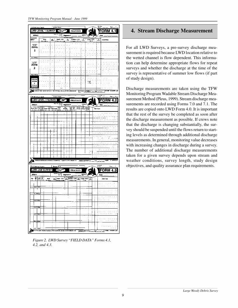
Figure 2. LWD Survey “FIELD DATA” Forms 4.1,4.2, and 4.3.
For all LWD Surveys, a pre-survey discharge mea-surement is required because LWD location relative tothe wetted channel is flow dependent. This informa-tion can help determine appropriate flows for repeatsurveys and whether the discharge at the time of thesurvey is representative of summer low flows (if partof study design).
Discharge measurements are taken using the TFWMonitoring Program Wadable Stream Discharge Mea-surement Method (Pleus, 1999). Stream discharge mea-surements are recorded using Forms 7.0 and 7.1. Theresults are copied onto LWD Form 4.0. It is importantthat the rest of the survey be completed as soon afterthe discharge measurement as possible. If crews notethat the discharge is changing substantially, the sur-vey should be suspended until the flows return to start-ing levels as determined through additional dischargemeasurements. In general, monitoring value decreaseswith increasing changes in discharge during a survey.The number of additional discharge measurementstaken for a given survey depends upon stream andweather conditions, survey length, study designobjectives, and quality assurance plan requirements.
4. Stream Discharge Measurement

Large Woody Debris Survey
10
TFW Monitoring Program Manual - June 1999
5. Large Woody Debris Survey Methods
This section provides the criteria and procedures forconducting the LWD Survey. It is organized in a se-quential format to facilitate accurate and consistentapplication of the methods. Both Level 1 and Level 2Surveys require conducting the Jam Survey. This sec-tion can be copied for crews to take out into the fieldfor referencing. Forms 4.1, 4.2, and 4.3 have been de-signed to record, organize, and track the informationgathered using these methods.
The methods section is divided into four sub-sections:1) Large Woody Debris and Channel Zone Identifica-tion; 2) LWD Level 1 Survey Procedure; 3) LWD Level2 Survey Procedure; and 4) LWD Jam Survey Proce-dure. The Level 1, Level 2, and Jam sub-sections arefurther divided into core and supplemental data col-lection parts. The LWD Survey procedure will be ex-plained as if a crew were conducting the survey forthe first time on one stream segment within a water-shed. This procedure can be applied on a watershedlevel by systematically following the same methodssegment by segment.
5.1 Large Woody Debris and Channel ZoneIdentification
For the purposes of both Level 1 and 2 methods, thereare three types of LWD: 1) logs; 2) rootwads; and 3)jams. Different information is collected for each type,so the first task is to identify the piece type being ob-served. Channel zone information is also a fundamen-tal part of both survey levels and jams and instruc-tions are provided to help field identification.
5.1.1 LWD Log Identification
A log is defined as a tree or section of tree and may ormay not include a root system (Figure 3). To qualifyas LWD, a log must meet four criteria:
Dead: No life evident at time of survey or no chanceof survival to the next survey season. Determiningchance of survival requires specific knowledge of treespecies and their ability to regenerate.
Root System: The root system (if present) is wholly orpartially detached from the ground to the point whereit is no longer capable of supporting the weight of thestem/bole.
Minimum Length/Diameter: Length measurements arefrom the base of the attached root-ball, if present, tothe furthest end of the log, even if the end is less thanthe minimum 0.1 meter diameter, or is jagged.
Diameter is measured to the nearest centimeter at themid-point along the length of each log. If the diametercannot be accurately measured, estimate the diameterand note its accuracy (i.e., ± 2 cm, ± 5 cm, ± 10 cm,etc.) as such in your field notes. In situations wherethe log is divided into several large branches at themid-point, measure the diameter immediately belowthe point where the branches fork. If the piece is round,measure the diameter with the spline of the caliperparallel to the channel substrate or water surface. Insituations of irregularly shaped boles, use the averageof two measurements taken perpendicular to each otherat the widest and narrowest axes, or use a loggers tape.
If a portion of a log is buried and its true length ordiameter cannot be determined, measure only the ex-posed portion of the log where it becomes visually ob-scured by other debris, sediment, vegetation, or water.Quick excavation by probing or surface debris removalto check for parameter dimensions is acceptable. When
LWD Log Criteria
1. Dead;2. The root system (if present) no longer supports the weight of the stem/bole;3. Minimum diameter of 0.1 meters (10 centimeters) along 2 meters of its length;and4. Minimum 0.1 meter of length extending into the bankfull channel (or optional above the

Large Woody Debris Survey
11
TFW Monitoring Program Manual - June 1999
Figure 3. Criteria for large woody debris log identification.
Diam eter 10 cenim eters for 2 m eters length
>
>
Length extends into the bankfull channe lRoot system no longer supportsweight of bole
Length m easuredto base o f
ro ot-ba ll
Length m easuredto last so lid p iece
Bankfull C hannel
Log
Yes
Dead
Diam eter 1 0 cm
Diam eter 1 0 cm
M idpoint Diam e ter < 1 0 cm
M idpoint Diam e ter > 1 0 cm
Yes
Yes
> 2 .0 m
NO
Green LeavesRoots support weight o
f bole

Large Woody Debris Survey
12
TFW Monitoring Program Manual - June 1999
a piece of wood forks into numerous small branches,such as the branches at the top of a tree, measure thelength to the point where the main bole is no longerdistinctly larger than the branches forking off of it.
Bankfull channel: To determine if the piece extendsinto the bankfull channel, refer to the “Channel ZoneIdentification” sub-section.
Difficult Situations
Green leaves: The presence of green leaves indicatesthat the tree or tree section is not fully dead at the timeof the survey and therefore is not counted as part ofthe core TFW-MP LWD data. Green leaves can be anindicator of a tree species’ ability to regenerate dis-turbed or damaged root systems. However, many co-operators have expressed a desire to collect informa-tion on these pieces. This can be accomplished bymodifying the forms using the following techniques:
��Form 4.1 and 4.3 - add a new column labeled“G” within each of the four LWD categories to record“green” pieces. If key piece information is not beingcollected, use that column but make sure to re-label it.��Form 4.2 - use the Piece Cat L - R column to notewhether the piece is a GL (green log) or a GR (greenrootwad).
Note: Data on “green LWD” must be separated outfrom core TFW-MP data before entering into the da-tabase at this time.
Forks: A fork is defined as a single bole that becomestwo boles above the estimated breast height position(DBH = 4.5 feet or 1.5 meters). Forked LWD arecounted as one piece with the diameter taken at itsmidpoint. Individual boles joined at the base or rootsystem (below DBH) are counted as individual piecesif each piece meets the minimum length and diametercriteria.
Branches: Branches that are attached to the bole ofthe tree are not counted as part of a piece’s length or asa separate piece regardless of their individual size.
Broken and very decayed pieces: LWD that has beenbroken into smaller pieces are counted separately ifthey meet minimum criteria. To determine if piecesare separate, imagine a crane picking-up one of thebroken pieces. Pieces that would not remain attached
are counted as individual LWD. This technique canalso be used to determine the length of an extensivelyrotted log or rootwad.
5.1.2 LWD Rootwad Identification
A rootwad is defined as a dead section of tree with arecognizable bole and root system, but its total lengthis less than the minimum 2.0 meter log length criteria(Figure 4). LWD rootwads are most often old stumpsleft over from timber harvests along the banks ofstreams. Rootwads are typically recruited into thestream channels through bank cutting and erosion. Thisprocess gradually exposes the roots of standing stumpsuntil they are detached and all or part of their lengthare within the bankfull channel. To qualify as a LWD,a rootwad must meet all four of the following criteria:
Length: Length is measured from the base of the“root-ball” to the furthest extent of the bole.
Diameter: Diameter is measured at the base of thebole where it meets the roots. In situations of irregu-larly shaped boles, use the average of two measure-ments taken perpendicularly to each other at the wid-est and narrowest axes, or use a loggers tape. If a boleis not present, it cannot be identified as a rootwad.
Root system: Rootwads must have an identifiable rootsystem and bole. Rootwads become LWD when theyhave fully detached from their original floodplain orterrace locations. This is an important distinction de-fining its function as channel debris. Exposed rootsthat are within the bankfull channel may have an in-fluence on channel morphology and provide habitatfor salmonids, but they do not have the ability to movealong the length of the channel and hence are not yet“debris.”
LWD Rootwad Criteria
1. Dead;2. Root system detached from original position;3. Minimum diameter of 0.2 meters (20 centimeters) with total length < 2 meters; and4. Minimum 0.1 meter of length extending into the bankfull channel (or optional above the bankfull channel).

Large Woody Debris Survey
13
TFW Monitoring Program Manual - June 1999
Detachment can be difficult to determine especially ifthe rootwad is still in an upright position and the rootsystem is buried. Count the piece if it can be deter-mined that it was originally anchored at a higher levelor if the bole is lower than the root system. If you areunsure that the rootwad has moved from its originallocation, do not count it. If the bole has fallen into thebankfull channel, the root system has obviously be-come detached and the piece is counted.
Bankfull channel: To determine if the piece extendsinto the bankfull channel, refer to the “Channel ZoneIdentification” sub-section.
5.1.3 LWD Jam Identification
Large woody debris jams are defined as channel-in-fluencing structures formed by accumulations of 10or more qualifying logs and rootwads (Figure 5). Indi-vidual jam pieces must meet the LWD criteria as de-fined above. While smaller accumulations may some-times function as debris jams, for TFW purposes theyare counted as individual pieces. This version of jamidentification has changed from the 1994 version intwo important ways. First, pieces do not have to be “incontact” or “touching” to be associated with a jam.Second, jam piece counts no longer include those
pieces whose lengths are completely within Zone 4.Refer to the “LWD Jam Survey Procedure” sectionfor information on collecting data comparable with the1994 version. To qualify as a jam, LWD must meet thefollowing criteria:
On most stream systems, jams are originally formedthrough in-channel sorting of LWD either randomly, oraround key members after the pieces have been re-cruited (Abbe and Montgomery, 1996). However, jamscan also be formed by hillslope processes where treesare blown down in domino fashion, where streamsideor hillslope slides enter a stream, or where depositionoccurs at the end of a debris torrent track (Swansonand Lienkaemper, 1978). Over time, jam accumula-tions can be influenced by both in-channel and hillslopeprocesses.
Figure 4. Criteria for large woody debris rootwad identification.
LWD Jam Criteria
1. Minimum 10 qualifying pieces of LWD either physically touching at one or more points, or associated with jam structure;2. Minimum 0.1 meter of one LWD piece’s length extending into the bankfull channel (or optional above the bankfull channel).
Length m easuredto base o f
ro ot-ba ll
Length m easuredto last so lid p iece
Bankfull C hannel
Rootwad
Dead
NO YesYes

Large Woody Debris Survey
14
TFW Monitoring Program Manual - June 1999
Figure 5. Criteria for large woody debris identification.
Debris Jam # 31 4 To ta l Pie c e s Re c o rde d
Debris Jam # 23 To ta l Pie c e s Re c o rde d
(7 p iec es o f jam with le ng thsc o m p le te ly in Zo ne 4 )
Debris Jam # 11 0 To ta l Pie c e s Re c o rd e d
(2 p iec es o f jam with le ng ths c o m p le te ly in Zo ne 4 )
Bankfu llChanne l
Edge
Bankfu llChanne l
Edge
7
7
8
8
8
9
9
9
1 0
1 0
1 11 2
1 0
1 11 2
1 3
1 4
4
4
4
5
5
5
6
7
6
1
1
1
2
2
2
3
3
3
6
LWD JAM S

Large Woody Debris Survey
15
TFW Monitoring Program Manual - June 1999
Ba nkfu ll C ha nne lBa nkfu ll C ha nne l
Ed g eBa nkfu ll C ha nne l
Ed g e
Dire c tly a b ove the Ba nkfu ll C ha nne l
O uts id e the Ba nkfu ll
C hanne l
O uts id e the Ba nkfu ll
C hanne l
We tte d C ha nne l
Zone 1
Zone 2
Zone 4Zone 3
Zone 4
Figure 6. Criteria for channel zone identification.
Jam structures can range from random accumulationsthat form a loose mat with little vertical stacking, todensely packed accumulations that result in the verti-cal stacking of five or more interwoven layers. Somejams may eventually integrate into and help developthe floodplain. Jams formed around key members areconsidered the most stable and have the greatest abil-ity to alter in-channel morphology, surface textures,water depths, and flow velocities. In these jams, theLWD that otherwise might be flushed through thatportion of the channel is deposited, usually by rackingup against the key members. This results in jams asso-ciated with higher quality aquatic and terrestrial ripar-ian habitats such as pools, sediment storage, and for-ested islands.
5.1.4 Channel Zone Identification
Four zones are used to characterize LWD channel lo-cations (Figure 6). The application of the channel zonesystem is discussed separately in the Level 1, Level 2,and Jam survey procedures.
Zone 1 is defined as the portion of the bankfull chan-nel that is wetted at the time of the survey, regardlessof whether the water is flowing or stagnant. Zone 1 isflow dependent and future surveys must be done at
corresponding stream discharge measurements to pro-duce comparable zone 1 data for trend monitoring.
Zone 2 is defined as the area between the bankfullchannel edge (BFCE) on both banks, below an imagi-nary line that connects those points, above the wettedchannel surface, and includes areas such as dry gravelbars. Think of the upper boundary line as a fiberglasstape stretched between the BFCE as if measuring thechannel’s bankfull width. Use the BFCE identifica-tion and confidence/default methods as described inthe Reference Point Survey method manual (Pleus andSchuett-Hames, 1998b).
Zone 3 is defined as the area found directly above Zone2 (bankfull channel). This zone typically includespieces that span or extend out over the bankfull chan-nel that provide cover or are considered LWD recruit-ment candidates.
Zone 4 is defined as the area outside of the bankfullchannel and Zone 3. This zone typically includes thefloodplain, terrace, and/or riparian areas. Pieces thatare completely in Zone 4 are never counted - includ-ing pieces associated with jams.

Large Woody Debris Survey
16
TFW Monitoring Program Manual - June 1999
Table 2. LWD Level 1 survey piece category and sizeclass identification by midpoint diameter criteria.5.2 LWD Level 1 Survey Procedure
This section is divided into core and optional supple-mental data collection parts. Data are collected on quali-fying individual LWD logs and rootwads during theLevel 1 survey. Refer to the LWD Jam Procedure sec-tion for recording accumulations of 10 or more pieces.In situations where no individual LWD pieces are foundwithin the segment, a Form 4.1 must still be filled-out.Put a “0” or “NO PIECES” on the form to documentthat a Level 1 survey was done but no pieces wereobserved. Enter this information into the database.
5.2.1 Level 1 Core Data Collection
Data is collected on all qualifying LWD pieces in theLevel 1 survey except those associated with debrisjams. In the Level 1 survey, each piece is assigned onetally mark on Form 4.1 in categories based on the LWDsize/type category and the lowest zone in which theminimum piece length could be measured. If key piecesare being identified, they are tallied separately fromthe non-key pieces on the right side of each box in theappropriate column. If key pieces are not distinguished,all pieces are recorded in the column’s left-hand box.
Begin the survey at the downstream end of the streamsegment and walk up the channel to avoid turbiditythat can obstruct LWD identification or accurate mea-surements. Systematically work up the channel andidentify qualifying LWD pieces. For each piece, deter-mine the category and size class for logs.
LWD Category Identification
In the LWD Level 1 survey, qualifying pieces are as-signed to one of four LWD categories: Rootwad; SmallLog; Medium Log; and Large Log (Table 2). Qualify-ing LWD rootwads are not divided into size classes.Qualifying LWD logs are divided into three size classesbased upon their diameter. Small logs have a midpointdiameter of equal to or greater than (≥) 10 centimeters(cm) and less than (<) 20 cm. Medium logs have amidpoint diameter of 20 cm and < 50 cm. Large logshave a midpoint diameter of ≥ 50 cm.
Lowest Channel Zone Identification
Next, identify the lowest channel zone in which theminimum piece length could be measured. A piece isassigned to Zone 1 if a minimum 0.1 meter of its lengthis within the water. A piece is assigned to Zone 2 if aminimum 0.1 meter of its length is within the bankfullchannel, but does not extend the minimum length intothe water.
Each piece must be assigned to only one LWD cat-egory/zone combination. Railroad chalk is useful formarking tallied pieces and to help prevent missing ordouble-counting pieces in complex areas. At the endof the segment survey, add the tally marks together oneach page for each category/zone combination andrecord the number in their corresponding “Tally To-tals” boxes.
5.2.2 Level 1 Supplemental Data Collection
Collection of supplemental data is optional when con-ducting the Level 1 Survey. Mark the appropriatecircles in the header band if either supplemental Zone3 or Key Piece information is being collected for thesurvey. For those interested in collecting informationon “Green” LWD, refer to the “Large Woody Debrisand Channel Zone Identification” section. Record a“0” in the appropriate columns on the form in situa-tions where a Level 1 survey was done, but no keypieces or Zone 3 pieces were identified. This informa-tion is entered into the database.
This section describes the procedures required for re-cording additional data on qualifying LWD pieces withlowest measurable lengths in Zone 3, and for deter-mining which Zone 1, 2 or 3 pieces also meet “KeyPiece” criteria. At this time, the TFW-MP database
LWD Category Diameter
Rootwad ≥ 20 cm
Small Log ≥ 10 cm to < 20 cm
Medium Log ≥ 20 cm to < 50 cm
Large Log ≥ 50 cm
NEW: Use one Form 4.1 per reference point interval to tallyLWD pieces. Record the number of the nearest downstreamreference point in the Downstream RP# box. The nearestdownstream reference point is determined by the location ofeach piece’s mid-point (see Figure 7).

Large Woody Debris Survey
17
TFW Monitoring Program Manual - June 1999
does not include Zone 3 piece counts or otherinformation in calculations or reports. The collection ofdata on qualifying LWD that also meets key piece cri-teria does not add to the total segment piece count.Tally marks are simply moved to the key piece sectionif they meet the additional criteria. Individual piecesthat are entirely within Zone 4 are not counted.
Zone 3 Tally (Optional ZONE 3 row): Assign onetally mark for each qualifying Zone 3 LWD piece toone of the four LWD categories. A piece is assignedto Zone 3 if a minimum 0.1 meters of its length extendsinto the area directly above the bankfull channel, anddoes not have a measurable length in Zones 2 or 1.Collection of Zone 3 piece information must be consis-tently applied across the entire segment.
Key Pieces Tally (Key Pieces columns): Tally marksfor regular LWD pieces that also meet key piece crite-ria are placed in corresponding “Key Pieces” tally sec-tions on Form 4.1. Record a “0” in the appropriatecolumns on the form where no pieces were identifiedfor that category. This information is entered into thedatabase. For example, a survey identified five LWDlarge size logs (≥ 50 cm diameter) in Zone 1. In situa-tions where cooperators chose not to collect supple-mental key piece data, all five tally marks would belocated in the regular piece section. However, if keypiece data is being collected and one of those piecesmeets key piece criteria, the tally box for that combi-nation would show four tally marks in the regular piecesection and one tally mark in the key piece section.
Table 3 provides the minimum volume by channelbankfull width required to qualify LWD as a key piece.To determine whether LWD meets key piece criteria,its diameter and length are measured to see if it meetsthe minimum criteria based on volume (Table 4).
To use Table 4, the first step is to select the bankfullwidth (BFW) category that corresponds with the seg-ment mean bankfull width. Use this column for theentire segment regardless of variation in channel widthalong the length of the segment. The second step is tomeasure the diameter of the candidate piece and roundthe result to the nearest 0.05 meter (5 cm). Locate thediameter in the left-hand column and follow the rowacross until it intersects with the appropriate bankfullwidth category. The number on that row is the mini-mum length required to meet key piece criteria.
EXAMPLE
Step 1: The stream segment being surveyed has amean bankfull width of 12.0 meters, and that fits in the10 - 15 meter category.Step 2: The candidate LWD log has a diameter of 53centimeters (0.53 meters) and this is rounded to 0.55meters. The candidate log has a length of 24 meters.Step 3: The intersection of the 0.55 meter diameterrow and the 10-15 m BFW column shows that a 0.55meter diameter piece must be at least 26 meters longbefore it qualifies as a key piece in a segment with amean 12 meter bankfull width. The candidate LWDdoes not meet the key piece criteria and is tallied asregular LWD.
Table 3. Key piece criteria based on mean segmentbankfull width and volume.
Table 4. Partial detail of key piece volume matrixbased on Watershed Analysis Fish Habitat Module,Table F-5. See Appendix C for complete matrix.
Key Piece Criteria
Mean Segment BankfullWidth (m)
Minimum Volume(m3)
0 to < 5 1.0
≥ 5 to < 10 2.5
≥ 10 to < 15 6.0
≥ 15 to < 20 9.0
≥ 20 9.0
MinDia.(m)
BFW0 to 5
BFW5 to 10
BFW10 to 15
BFW15 to 20
Min Length (m)
0.50 6 13 31
0.55 5 11 26
0.60 4 9 22 32
0.65 3 8 19 28
0.70 3 7 19 24
0.75 3 6 14 21

Large Woody Debris Survey
18
TFW Monitoring Program Manual - June 1999
Figure 7. Assign LWD pieces to the nearest downstreamreference point based on its midpoint location.
5.3 LWD Level 2 Survey Procedure
Data are collected on all qualifying individual LWDlogs and rootwads during the Level 2 survey exceptthose associated with debris jams. Fill-out one row onForm 4.2 for each qualifying piece of LWD. Refer tothe LWD Jam Procedure section for recording accu-mulations of 10 or more pieces. Mark the appropriatecircles in the header band to document whether mea-surements are recorded in meters or feet.
Identification of key pieces is not required on Form4.2 since piece diameters and lengths are recorded andthe database will sort out LWD pieces that meet thekey piece criteria. In situations where no individualLWD pieces are found within the segment, a Form 4.2is still required. Put a “0” or “NO PIECES” on theform to document that a Level 2 survey was done butno pieces were observed. This information is enteredinto the database. Mark the blank row after the lastjam record “END OF SURVEY” for documentation.
5.3.1 Level 2 Core Data Collection
Piece Number (Piece # column): Record the piecenumber. Assign each qualifying LWD piece a uniquenumber, beginning with “1” and continuing sequen-tially upstream to the last piece in the stream segment.
Downstream Reference Point Association (Dwn Ref# column): Record the number of the nearest down-stream reference point. Each LWD piece is associatedwith a 100 meter reach delineated by established ref-erence points. The nearest downstream reference pointis determined by the location of each piece’s mid-point(Figure 7). This system prevents double countingpieces in two reaches or segments.
Log/Rootwad Identification (Piece Cat L/R column):Record either (L) for Log or (R) for Rootwad.
Diameter Measurement (Piece Dia cm column):Measure and record the diameter at the mid-point ofthe piece to the nearest centimeter or 0.01 meter. Onirregularly shaped pieces where the bole is not round,two measurements should be taken and averaged. Usethe Field Notes column to record calculations.
Piece Length Measurement by Channel Zone Lo-cation (Piece Length column): Record the length ofeach piece by channel zone to the nearest 0.1 meter.Refer to the LWD identification section for piece lengthmeasurement criteria. If there is no length in one ormore of the zones, place a “0” or diagonal mark in thatbox. This provides documentation that a measurementwas not simply forgotten. Total lengths and volumesare computed during data processing. Form 4.2 hasseparate columns for each of the channel zone loca-tions. Total length is calculated in the database.
A good technique is to identify all the zone bound-aries on the piece before taking the length measure-ments (Figure 8). A piece of railroad chalk is usefulto help mark and remember boundary locations.
� Zone 1 lower boundary: The lower boundary of Zone1 is the end of the piece located within the wetted chan-nel. In situations where locating the end of a piece isdifficult due to water visibility, water depth, sedimentor other obstructions, the end of the piece is the fur-thest extent of visible or easily verified length.
RP# 4
x
x
x
x
Piece m idpo int: As s ign to Downstream RP# 3Piece m idpo int: As s ign to Downstream RP# 4

Large Woody Debris Survey
19
TFW Monitoring Program Manual - June 1999
Figure 8. Measuring Zone 1, 2, 3, and 4 lengths along a piece of LWD.
� Zone 1/Zone 2 boundary: Identify the point alongthe length of the piece where it leaves the wetted chan-nel. This point is often found where the waterline lasttouches the underside of the log. Mark the correspond-ing location with chalk along the top or side of thepiece for measurement reference.
� Zone 2/Zone 3 boundary: Identify the point alongthe length of the piece where it leaves the bankfullchannel. Mark the corresponding location with chalkalong the top or side of the piece for measurement ref-erence. Often, this point is found where an estimatedbankfull waterline would last touch the underside ofthe piece.
In situations where a bankfull channel edge is nearby,the zone 2/3 boundary can be identified by using anextend stadia rod and torpedo level. One end of thestadia is placed at the BFCE and then the rod is lev-eled. Keeping the rod level, swing it upstream or down-stream to identify the location of the piece boundary.
In situations where the bankfull channel edge is not
close enough or in complex areas, use the confidence/default technique. Working from inside the channelout or up, identify the point on the piece where 100 %confidence is lost that it is still in Zone 2. Workingfrom outside the channel in or down, identify the pointon the piece where 100 % confidence is lost that it isstill in Zone 3. Reassess the confidence range and ad-just if necessary. The default Zone 2/3 boundary isidentified as mid-point within the confidence range.
� Zone 3/Zone 4 boundary: Identify the point alongthe length of the piece where it crosses the verticalboundary of the bankfull channel. For this boundary,the furthest extent of influence is often on the top orsides of the piece. Mark the corresponding locationwith chalk along the top or side of the piece for mea-surement reference.
Use the BFCE point established by Zone 2 identifica-tion and imagine a boundary line from that pointstraight up along the length of the bank. The stadiarod/torpedo level and confidence/default techniquescan also be used to identify this measurement point.
9 00
1
2
3
4
Piece Cente rline
Ba nkfu ll C hanne l
Abo veBa nkfu ll
C hanne l
O uts id eBa nkfu ll
C hanne l
We tte d C hanne l
Length Zone 1
Length Zone 2
Length Zone 3
Length Zone 4
Zone Length a long p iece centerline
Large Woody Debris Survey
20
TFW Monitoring Program Manual - June 1999
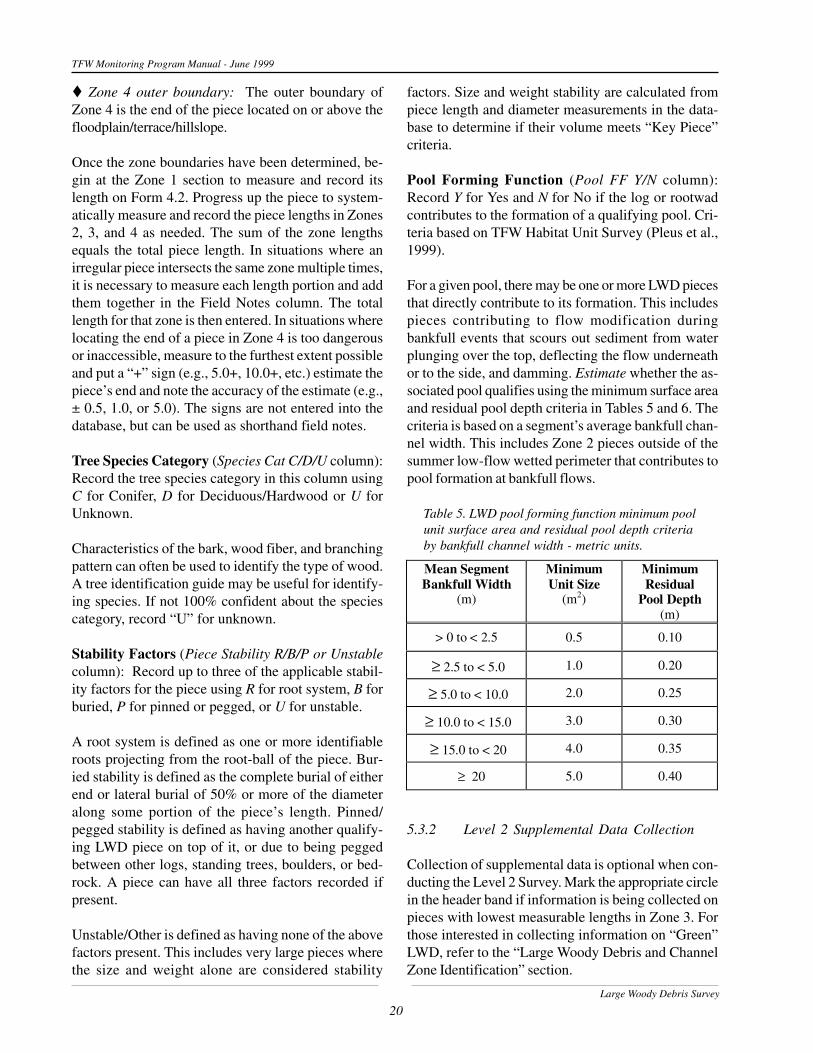
� Zone 4 outer boundary: The outer boundary ofZone 4 is the end of the piece located on or above thefloodplain/terrace/hillslope.
Once the zone boundaries have been determined, be-gin at the Zone 1 section to measure and record itslength on Form 4.2. Progress up the piece to system-atically measure and record the piece lengths in Zones2, 3, and 4 as needed. The sum of the zone lengthsequals the total piece length. In situations where anirregular piece intersects the same zone multiple times,it is necessary to measure each length portion and addthem together in the Field Notes column. The totallength for that zone is then entered. In situations wherelocating the end of a piece in Zone 4 is too dangerousor inaccessible, measure to the furthest extent possibleand put a “+” sign (e.g., 5.0+, 10.0+, etc.) estimate thepiece’s end and note the accuracy of the estimate (e.g.,± 0.5, 1.0, or 5.0). The signs are not entered into thedatabase, but can be used as shorthand field notes.
Tree Species Category (Species Cat C/D/U column):Record the tree species category in this column usingC for Conifer, D for Deciduous/Hardwood or U forUnknown.
Characteristics of the bark, wood fiber, and branchingpattern can often be used to identify the type of wood.A tree identification guide may be useful for identify-ing species. If not 100% confident about the speciescategory, record “U” for unknown.
Stability Factors (Piece Stability R/B/P or Unstablecolumn): Record up to three of the applicable stabil-ity factors for the piece using R for root system, B forburied, P for pinned or pegged, or U for unstable.
A root system is defined as one or more identifiableroots projecting from the root-ball of the piece. Bur-ied stability is defined as the complete burial of eitherend or lateral burial of 50% or more of the diameteralong some portion of the piece’s length. Pinned/pegged stability is defined as having another qualify-ing LWD piece on top of it, or due to being peggedbetween other logs, standing trees, boulders, or bed-rock. A piece can have all three factors recorded ifpresent.
Unstable/Other is defined as having none of the abovefactors present. This includes very large pieces wherethe size and weight alone are considered stability
factors. Size and weight stability are calculated frompiece length and diameter measurements in the data-base to determine if their volume meets “Key Piece”criteria.
Pool Forming Function (Pool FF Y/N column):Record Y for Yes and N for No if the log or rootwadcontributes to the formation of a qualifying pool. Cri-teria based on TFW Habitat Unit Survey (Pleus et al.,1999).
For a given pool, there may be one or more LWD piecesthat directly contribute to its formation. This includespieces contributing to flow modification duringbankfull events that scours out sediment from waterplunging over the top, deflecting the flow underneathor to the side, and damming. Estimate whether the as-sociated pool qualifies using the minimum surface areaand residual pool depth criteria in Tables 5 and 6. Thecriteria is based on a segment’s average bankfull chan-nel width. This includes Zone 2 pieces outside of thesummer low-flow wetted perimeter that contributes topool formation at bankfull flows.
5.3.2 Level 2 Supplemental Data Collection
Collection of supplemental data is optional when con-ducting the Level 2 Survey. Mark the appropriate circlein the header band if information is being collected onpieces with lowest measurable lengths in Zone 3. Forthose interested in collecting information on “Green”LWD, refer to the “Large Woody Debris and ChannelZone Identification” section.
Table 5. LWD pool forming function minimum poolunit surface area and residual pool depth criteriaby bankfull channel width - metric units.
Mean SegmentBankfull Width
(m)
MinimumUnit Size
(m2)
MinimumResidual
Pool Depth(m)
> 0 to < 2.5 0.5 0.10
≥ 2.5 to < 5.0 1.0 0.20
≥ 5.0 to < 10.0 2.0 0.25
≥ 10.0 to < 15.0 3.0 0.30
≥ 15.0 to < 20 4.0 0.35
≥ 20 5.0 0.40

Large Woody Debris Survey
21
TFW Monitoring Program Manual - June 1999
Table 6. LWD pool forming function minimum poolunit surface area and residual pool depth criteriaby bankfull channel width - English units.
Figure 9. LWD orientation Option 1 system based onBilby and Ward (1991).
This section describes the procedures required for re-cording (a) Zone 3 counts, (b) channel orientation func-tion, c) decay class, and (d) sediment storage data onqualifying LWD pieces. At this time, the TFW-MP da-tabase does not include Zone 3 piece counts or otherinformation in calculations or reports. Information onpiece orientation, decay, and sediment storage providesgreater characterization of established qualifying LWDand does not affect the total piece count.
Zone 3 Piece Count
A piece is counted if a minimum 0.1 meter of its lengthis within Zone 3 (the area directly above the bankfullchannel), but not into the bankfull channel or water.Piece numbering follows the normal sequential countprogression. The only difference in collection of piececharacteristic data is that there are no length measure-ments in the Zone 1 or 2 columns. Collection of Zone 3piece information must be consistently applied acrossthe entire segment.
Channel Orientation
Channel Orient column: Orientation is measured torepresent a piece’s horizontal position within the bankfullchannel. Option 1 (Bilby and Ward, 1991) - record ei-ther A for parallel, B for perpendicular, C for down-stream, or D for upstream. Option 2 (Robison andBeschta, 1990) - record the orientation degree between00 and 1800. A compass is used to determine categoryor actual orientation degrees. Orientation is based bothupon the angle of the bole’s length axis in relation tothe estimated direction of flow at bankfull stage and
the position of the root system and/or direction of thesmall-diameter end depending upon the option.
Option 1: This method is based on eight 450 quadrants(Figure 9). Parallel (A) is defined as a piece with it’slength axis oriented between either 337.50 and 22.50,or 157.50 and 202.50. Perpendicular (B) is defined as apiece with it’s length axis oriented between either 67.50
and 112.50, or 247.50 and 292.50. Root system or small-diameter end direction is not a factor in category A orB orientation. Downstream (C) is defined as a pieceoriented at any other angle with it’s small-diameterend pointed downstream (root system upstream). Up-stream (D) is defined as a piece oriented at any otherangle with it’s small-diameter end pointed upstream(root system downstream).
Option 2: Pieces with their root system in the upstreamdirection (small-diameter end downstream) are as-signed an orientation angle of between 0 and 89 de-grees (Figure 10). Pieces with their root system in thedownstream direction (small-diameter end upstream)are assigned an orientation angle of between 91 and180 degrees. Direction of root system/small diameterend is not a factor for 90 degree oriented pieces.
BB
A
C C
D
Bankfu ll C hannel Orientation
D
A
00
9 00
1 8 00
2 9 2 .50
6 7 .50
1 5 7 .50
2 4 7 .50
2 0 2 .50
1 1 2 .50
2 2 .503 3 7 .5
0
F lo w
2 7 00
Option 1
Mean SegmentBankfull
Width(feet/tenths)
MinimumUnit Size
(feet/tenths2)
MinimumResidual Pool
Depth(feet/tenths)
> 0 to 8.2 5.4 0.33
≥ 8.2 to 16.4 10.8 0.66
≥ 16.4 to 32.8 21.5 0.82
≥ 32.8 to 49.2 32.3 0.98
≥ 49.2 to 65.6 43.1 1.15
≥ 65.6 53.8 1.31
Errata 7/7/99

Large Woody Debris Survey
22
TFW Monitoring Program Manual - June 1999
Decay Class
Piece Decay column: Option 1 (Robison and Beschta,1990): Record a single number code between 1 and 5related to the decay class for each piece. Option 2(Grette, 1985): Record a single number code between1 and 7 related to the decay class for each piece.
Option 1: This option is provided for those coopera-tors interested in comparing decay class results to re-
search conducted by Robison and Beschta (1990).Table 7 provides the criteria for determining decay classusing this system.
Option 2: This option is provided for those coopera-tors interested in comparing decay class results to re-search conducted by Grette (1985) and McHenry etal. (1998). Table 8 provides the criteria for determin-ing decay class using this system.
Definitions of decay indicators
Bark: Bark is defined as the tough protective coveringaround the exterior of tree roots, stems, and branches.Different species produce different thicknesses and tex-tures. Intact bark is that which maintains its integritywith the inner wood surface and cannot be removedby hand. This includes situations where the exteriorlayer of bark has been severely abraded, but does notexpose the inner wood surface. Loose bark no longeradheres to the inner wood surface and can be movedor removed by hand.
Branches/Limbs/Twigs: Branches and twigs are thesecondary and greater stems extending from the maintree bole. Branches and twigs are present where stemdiameters can be measured and absent where they can-not be measured as they do not extend past the stemcollar at the main tree bole.
Surface Texture: The surface is defined as the outerlayer of the tree wood. In less decayed pieces, this sur-face would contact the inner layer of bark. In pieceswith advanced decay, the surface is the outermost layer
Figure 10. LWD orientation Option 2 based onRobison and Beschta (1990).
Table 7. A five-class decay system for evaluating coniferous and deciduous large woody debris from Robison andBeschta (1990).
Decay Class Bark Twigs3 cm; 1.2 in
SurfaceTexture Shape Wood Color
1 Intact Present Intact/Firm Round Original
2 Intact Absent Intact/Firm Round Original
3 Trace AbsentSmooth to somesurface abrasion
RoundOriginal todarkening
4 Absent AbsentAbrasion to
some holes andopenings
Round to oval Dark
5 Absent AbsentVesicular withmany holes and
openingsIrregular Dark
Bankfu ll C hannel Orientation
00
1 8 00
1 3 50
1 3 50
4 50
4 50
F lo w
9 00
Option 2
9 00

Large Woody Debris Survey
23
TFW Monitoring Program Manual - June 1999
Table 8. A seven-class decay system for evaluatingconiferous and deciduous large woody debris fromGrette (1985).
of decomposed wood. A firm surface texture is wherethe integrity of the wood strength has not been lost.The texture is often smooth to the touch as if the barkhas just been removed. A firm surface texture is alsoidentified where abrasion has roughened or gouged theouter wood layer, but the integrity of the wood strengthis still intact. Deteriorating or decomposing surface tex-ture is where the wood’s chemical and biological struc-ture is breaking down and affecting the integrity of thewood strength. A firm surface would produce woodchips if cut with a knife, and a deteriorating surfacewould produce multiple wood fibers and parts. Indica-tions of deterioration range from pockets of outer sur-face softening to rotten where porous surface woodeasily crumbles to the touch.
Center Integrity: The center is defined as the core ofthe wood where the first growth rings are located. Solidintegrity is where wood strength has not been deterio-rated as defined above. Estimation of integrity can bemade at observation points such as the piece ends andwhere holes are available due to deterioration by chemi-cal, biological, or animal factors. Accurate verificationrequires taking core samples. Pieces with very ad-vanced decay are not included in LWD counts whereit is estimated that they could break or crumble intonon-qualifying LWD pieces if moved.
Sediment Storage
Sed Stor Y/N column: Assign each piece either a “Y”for yes or “N” for no if it is directly associated withsediment storage. Sediment storage is defined as meet-ing all of the following criteria: 1) a minimum 1 squaremeter surface area deposit of coarse or fine substrate;2) retained within the bankfull width of the streamchannel; and 3) by direct association with the LWDpiece. Without the presence of the identified piece,sediment would not likely accumulate in that location,or it would become mobilized if the wood was re-moved. This means that the stored sediment has to beat a higher elevation than the corresponding generalchannel sediment level. Sediment sizes in storage de-posits are often of a different size class than the pre-dominant bed material. The boundaries of stored sedi-ment are typically defined by breaks in channel gradi-ent and differences in composition of bed materials.
5.4 LWD Jam Survey Procedure
Data is collected on qualifying LWD jams for both theLevel 1 and Level 2 surveys. Fill-out one row on Form4.3 for each qualifying LWD jam. Accumulations ofless than 10 pieces are recorded as individual LWDpieces according to the level of survey being con-ducted. Although jams must always contain 10 or morepieces, only pieces with measurable lengths extend-ing into Zones 1, 2, and 3 are recorded on the fieldform. Therefore, it is possible to record less than 10pieces on small jams where some of the piece lengthsare totally in Zone 4. Review the “LWD Jam Identifi-cation” section for resolving complex situations. Insituations where no LWD jams are found within thesegment, it is still required that a Form 4.3 be filled-out. Put a “0” or “NO JAMS” on the form to docu-ment that a jam survey was done but no jams wereidentified. This information is entered into the data-base. Mark the blank row after the last jam record“END OF SURVEY” for documentation.
Walking on top of LWD jams can be difficult and dan-gerous, so jam information is intended to be collectedwhile walking around the outside of the unit and doesnot necessitate actual measurement of individual piecesof wood.
DecayClass Bark Limbs Surface
Texture Center
1 Intact Present Firm Solid
2 Intact Absent Firm Solid
3Loose
orabsent
Absent Firm Solid
4 Absent AbsentSlightlyrotted
Solid
5 Absent AbsentExtensively
rottedSolid
6 Absent AbsentCompletely
RottedSolid
7 Absent AbsentCompletely
Rotted Rotted

Large Woody Debris Survey
24
TFW Monitoring Program Manual - June 1999
5.4.1 Jam Core Data Collection
Jam Number (Jam # column): Record the sequentialjam number. Assign each qualifying LWD jam a uniquenumber, beginning with “1” and continuing sequen-tially upstream to the last jam in the stream segment(e.g., 1, 2, 3, 4, etc.).
Jam Reference Point Association (Dwn Ref # col-umn): Record the number of the nearest downstreamreference point. The nearest downstream referencepoint is determined by the location of the jam’s mid-point (Figure 11). This system prevents doublecounting jams or jam pieces in two reference pointreaches. Jam piece numbers can be split at referencepoints using the percent estimation technique.
Percent Estimation Technique
One row is filled out for the entire jam’s piece countand associated with the downstream reference pointbased on its midpoint location. In the Field Notes col-umn, record the estimated percentage of pieces whosemidpoints are downstream and upstream of the refer-ence point boundary. Percentages can be estimated in10 percent or 25 percent groupings. The total of thedownstream and upstream percentages must equal 100percent.
Jam Channel Location (Lowest Zone column):Record either zone number 1, 2, or optional 3.
Record the jam’s lowest channel zone. A jam is as-signed to Zone 1 if at least one of its lowest LWDpieces extends its length a minimum 0.1 meters intothe water. A jam is assigned to Zone 2 if at least one ofits LWD pieces extends its length a minimum 0.1 metersinto the bankfull channel area, but none of the pieceshas a measurable length in Zone 1.
Jam Pool Forming Function (Pool FF column):Record “Y” for Yes or “N” for No if the jam contrib-utes to the formation of a qualifying pool. For a givenpool, there may be one or more individual LWD pieceswithin a jam that have contributed to its formationthrough direct or indirect means. This includes flowmodification that scours out sediment from water plung-ing over the top, deflecting the flow underneath or tothe side, and damming.
Use the TFW Habitat Unit Survey method manual poolcriteria based on a segment’s average bankfull chan-nel width for minimum surface area and residual pooldepth to estimate whether associated pools qualify (seeTables 5 and 6). This includes Zone 2 jams outside ofthe summer low-flow wetted perimeter that you deter-mine contribute to associated pool formation at bankfullflows.
Tally of Visible Pieces by Category (Tally of Vis-ible Pieces column): Record a tally mark represent-ing an individual piece of LWD in the appropriate typeand size class column. Associated jam pieces that arecompletely within Zone 4 are not tallied. The percent-age of Zone 1, 2, and 3 pieces tallied out of the totalestimated jam can be recorded in the Field Notes col-umn. Record a “0” in the appropriate columns on theform where no pieces in that category were identi-
fied. This information is entered into the database.
Walk around the debris jam and count the visible piecesthat meet the minimum size criteria for rootwads andlogs. LWD tallies and diameter size classes are esti-mated in unsafe conditions. Rootwads are tallied as asingle size class. Logs are tallied corresponding to theirdiameter size class as either small (S-LOG 10 to <20 cm), medium (M-LOG 20 to < 50 cm), or large(L-LOG 50 cm).
Figure 11. Assign LWD jams to the nearest downstreamreference point based on midpoint location.
RP# 4
Jam m idpo int: As s ign to Downstream RP# 4
7
x
x

Large Woody Debris Survey
25
TFW Monitoring Program Manual - June 1999
Because it is often not possible to see both ends of logsthat go through the middle of large jams, it may bedifficult to know if you are missing a piece or countingthe same piece twice. Using railroad chalk to marktallied pieces is helpful to prevent this problem. Esti-mation of log diameter sizes requires experience witha log caliper to calibrate your eye. The tally marks areadded together at the end of the survey and recordedalong the Tally Totals row under their appropriate LWDtype and size class.
Splitting Jams at Segment Boundaries
Single jams with pieces influencing two or more studyreaches are split according to the estimated midpointlocations of individual pieces. The overall jam’s mid-point location, an estimated percentage of total pieceswithin the study reach, and a brief description of thejam are documented in the Field Notes column.
For example, Figure 12 represents a sprawling jam withpieces influencing three segment study reaches. TheCrazy Creek Segment 3 portion of the jam wouldrecord a unique jam number, nearest downstream ref-erence point number for that portion of the jam, the
lowest zone of the overall jam, the pool formingfunction of the overall jam, and a tally of visible piecesbased on piece mid points falling in that segment. TheCrazy Creek Segment 4 portion of the jam can recordthe same number if known or a unique jam number, adifferent downstream reference point number, the samelowest zone and pool forming function describing theoverall jam, and a tally of visible pieces based on piecemid points falling in that segment. The Crazy Creektributary Segment 1 jam information would follow thesame process as Segment 4. In general, only one seg-ment is part of the study plan and other segment infor-mation is not collected. If all three segments wheresurveyed, the sum of the pieces from each segmentwould reflect the total jam piece count.
5.4.2 Jam Supplemental Data Collection
This section describes the procedures required for re-cording data on additional qualifying LWD jams withlowest zone of 3 and for identifying individual pieceswithin a qualifying jam that meet key piece criteria.Collection of supplemental data is optional when con-ducting the Jam survey. Mark the appropriate circlesin the header band if either Zone 3 or Key Piece infor-mation is being collected for the survey. Jams that areentirely within Zone 4 are not counted. Record a “0”in the appropriate columns on the form in situationswhere a jam survey was done, but no key pieces orZone 3 pieces were identified. This information is en-tered into the database.
This version of the LWD Jam Survey does not includein the total jam piece counts those individual jam pieceswith lengths completely within Zone 4. Jam piece countcomparisions to 1994 methods can be accomplishedby using the next row on Form 4.3 to record Zone 4piece information (not entered into database). Use thesame jam and reference point numbers, but record a“4” in the Lowest Zone column. For those interestedin collecting information on “Green” LWD, refer tothe “Large Woody Debris and Channel Zone Identifi-cation” section.
Zone 3 Jam Count: A jam is assigned to Zone 3 if atleast one of its lowest LWD pieces extends its length aminimum 0.1 meters into the area directly above thebankfull channel, and no jam pieces have measurablelengths in Zones 2 or 1. Jam numbering follows thenormal sequential count progression. The only
Figure 12. Splitting jam piece counts at segmentboundaries.
12
34
56
7
8
9
Crazy CreekSegm ent 3
(9 jam pieces)
Crazy CreekSegm ent 4
(8 jam pieces)
Tributary CreekSegm ent 1
(3 jam pieces)
Sp litting Ja ms at Seg ment Boundaries

Large Woody Debris Survey
26
TFW Monitoring Program Manual - June 1999
difference in collection of jam data is that a “3” is re-corded in the Lowest Zone column. Collection of Zone3 piece information must be consistently applied acrossthe entire segment. At this time, the TFW-MP data-base does not include Zone 3 jam or piece informationin calculations or reports.
Key Pieces Tally: Tally marks for qualifying individualLWD regular pieces that also meet key piece criteriaare placed in corresponding Key Pieces tally sections.Refer to the “Level 1 Supplemental Data Collection”section for specific information on key piece identifi-cation procedures and documentation. The collectionof key piece characteristic data on qualifying LWDpieces within an established jam does not add to thetotal segment piece count. Tally marks are simplymoved to the key piece section if they meet theadditional criteria.

Large Woody Debris Survey
27
TFW Monitoring Program Manual - June 1999
6. Post-Survey Documentation
After completion of the field portion of the LargeWoody Debris Survey, field forms need to be orga-nized, supplemental information and calculations com-pleted, and all forms and information error checkedbefore the data is ready to be entered into the data-base. The objective of this section is to organize thedata to ensure that this survey can be repeated the sameway in the future by different crews.
6.1 Finalizing Forms 4.0, 4.1, 4.2 and 4.3
Organize the forms and check for missing sheets. Sys-tematically check each LWD Survey form for com-pleteness. All parameter blanks and boxes should con-tain information or a “/” to designate that no informa-tion is available or needed.
6.1.1 All Forms
The following list provides guidance on some com-mon tasks:
��Page numbering is related to form type. Count thenumber of total pages separately for Forms 4.0, 4.1,4.2, and 4.3.
��The page number should be filled in as used dur-ing the survey (e.g., Page 1 of __, Page 2 of __, Page 3of __, etc.). Forms that have been copied on both sideof one sheet of paper will count as two separate pages.
��The total number of pages for each type of form isfilled in at the end of the survey (e.g., Page 1 of 6,Page 2 of 6, Page 3 of 6, etc.).
��Organize the field forms by type and then by pagenumber for easy reference. It is common to have dif-ferent totals for each type.
6.1.2 Form 4.0
Study Design Information
Begin/End Survey Dates: Record the dates based onForms 4.1, 4.2, and 4.3 that LWD Survey field datacollection began and ended for that segment. The Be-gin Survey Date is a key database field used to trackand identify this specific survey.
Survey Length: Where the entire segment was sur-veyed, record the segment length as documented inthe “Study Design Information” section on the Refer-ence Point Survey Form 2H or the database report.Where only portions of the segment were surveyed,record the total length of reach actually surveyed withinthe segment.
Survey Coverage: Fill-in the survey’s coverage circleand percentage of the survey length that best appliesto the survey. Mark WHL if the whole or entire seg-ment or sub-segment was inventoried for sample col-lection (100%). Mark PRT if the survey was appliedon a consecutive length of a partial segment/sub-seg-ment. For example, where only the first 500 meters ofa 2,000-meter-length segment will be inventoried forsample collection (25%). Mark SUB if the survey wasapplied using a random or systematic placement sub-sampling strategy. For example, where every other 100meter interval reach will be inventoried for samplecollection (50%). Mark PSB if a combination of PRTand SUB was applied. Mark OTH if your study designdiffers from the above.
Partial/Other Survey Location: These locations areassociated with survey length lower and upper bound-aries - that is, the boundaries encompassing the sec-tion of stream actually surveyed. Record the WRIAriver/stream mile locations to the nearest tenth of amile (0.0 - 9999.9) and reference point numbers (0 -9999).
Survey Notes
This section is provided to make brief notes related tounique survey conditions and problems encountered.

Large Woody Debris Survey
28
TFW Monitoring Program Manual - June 1999
Note any modifications to the TFW-MP Large WoodyDebris Survey criteria used to meet individual coop-erator needs. This includes minimum diameter, length,or other identification criteria, channel zone system,jam size, decay class etc. Additional information canbe included on the back of the form or on separatesheets of paper. If separate sheets are used, they needto be included in the Page __ of __ information andhave the key header information listed at the top ofeach page.
Discharge Information
Record all date and discharge measurements fromForms 7.0 and 7.1 that apply to this survey.
6.1.3 Form 4.1
Count the tally marks for each LWD category and zone,and record the sum in their respective Tally Totals rowand box.
6.1.4 Form 4.3
Count the tally marks for each LWD category, andrecord the sum in their respective Tally Totals row andbox.
6.2 Error Checking
Error checking of field forms is a very important taskand sufficient time should be taken to complete it. It isbest done during or immediately after data collection.It becomes more difficult to reconcile discrepanciesand track down correct information the more timepasses since the survey was completed. Where infor-mation cannot be corrected, the data may not be use-ful for monitoring purposes. Contact the TFW-MP forassistance in determining how to handle missing datafields.
Review Forms 4.0, 4.1, 4.2 and 4.3 plus all other docu-ments compiled during the Large Woody Debris Sur-vey. Have a second person look them over for com-pleteness, legibility and errors. Every page of everyform requires error checking for legibility, completeand consistent header information, obvious measure-ment and transcription errors, and calculation errors.Work systematically through each section and whencompleted, put your initials and date in the ErrorChecked by box at the bottom of each page. If the per-son error checking the data is not a crew member, theirfull name and task should be recorded in the SurveyNotes section of Form 4.0.

Large Woody Debris Survey
29
TFW Monitoring Program Manual - June 1999
7. Data Management
The TFW Monitoring Program offers data manage-ment services to help cooperators quickly analyze datacollected with the program methods and to producestandard monitoring reports. The heart of the serviceis a database system housed at the Northwest IndianFisheries Commission. This database calculates param-eters, produces reports and archives electronic ver-sions of the data. The database is also an importantarchive of monitoring data that can be used for devel-oping study designs and identifying control or refer-ence sites. This section describes the process for datapreparation, data processing and archiving, and dataanalysis.
7.1 Data Preparation
Before data entry can occur for the Large Woody De-bris Survey, some preparation must be done. The fol-lowing materials are needed:
��completed and error-checked Forms 4.0, 4.1, 4.2, and 4.3 as needed for each segment;��a data entry system and set of instructions;��an “Ambsys” data dictionary;��a copy of the completed Stream Segment Identification Form 1.0;��and a copy of the completed Reference Point Survey Form 2.H.
Before the data entry process can begin, an entry sys-tem must be selected. Choose a data entry system fromthe list below and request a free copy and user’s manualfrom the TFW Monitoring Program. The database hasthree entry system options for survey data. These are:
��Microsoft Excel 4.0 pre-formatted spreadsheets;��Lotus 1-2-3 (vers. 3) pre-formatted spreadsheets;� Microsoft Access 7.0 pre-formatted entry forms.
Refer to Appendix E for an example of the Excel pre-formatted spreadsheet. Select a spreadsheet format ifyour data requires conversion from English to metricunits. Replace all English unit measurements with metricequivalents. Read the instructions for the data entrysystem and the Ambsys data dictionary, noting the fieldtypes and data constraints (what type of data can beentered into each field).
7.2 Data Processing, Products and Archiving
Open the section of the entry system pertaining to theLWD Survey on your computer. You must completethe header, Level 1 or Level 2, and the Debris Jamdetail forms. Following the entry system instructions,enter the data from Forms 4.0, 4.1 or 4.2, and 4.3 asdirected. After the data has been entered and the ses-sion saved, error check the data entry. The most effi-cient process is to have one person read the data offthe screen and another check it with the original fieldform. Save the file a final time after verifying theaccuracy of the entered data.
Data can be sent to the TFW Monitoring Program us-ing several different methods. A few are describedhere. Gather together:
��Copies of the field forms;��Copy of USGS topographic map section(s) with the stream segment locations marked; and��An electronic version of the data.
Copies of all survey field forms and other documenta-tion can be hand delivered, mailed, or faxed to theNorthwest Indian Fisheries Commission. Copies of theUSGS topographic map sections can be hand deliv-ered, mailed, or faxed and must contain the followinginformation: upstream and downstream segment bound-aries along the stream, township, range, section, con-tour interval, and map name and date. The electronicversions of the data can be sent via e-mail, CD, or on afloppy disk. After the program receives the electronicfiles, the data is imported into the database by a TFW-MP staff person.
Safe and efficient archiving is also provided throughData Management Services. The data generated byindividual cooperators is archived electronically in thedatabase system. Hard copies of the field forms, topo-graphic maps and supplemental information arearchived at the TFW-MP facility to meet quality as-surance needs and to reduce the chance of loss due topersonnel changes or destruction. Access to coopera-tor data can be limited by request. Call for informationon the data access policy.
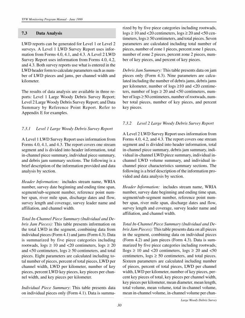
Large Woody Debris Survey
30
TFW Monitoring Program Manual - June 1999
7.3 Data Analysis
LWD reports can be generated for Level 1 or Level 2surveys. A Level 1 LWD Survey Report uses infor-mation from Forms 4.0, 4.1, and 4.3. A Level 2 LWDSurvey Report uses information from Forms 4.0, 4.2,and 4.3. Both survey reports use what is entered in theLWD header form to calculate parameters such as num-ber of LWD pieces and jams, per channel width andkilometer.
The results of data analysis are available in three re-ports: Level 1 Large Woody Debris Survey Report;Level 2 Large Woody Debris Survey Report; and DataSummary by Reference Point Report. Refer toAppendix E for examples.
7.3.1 Level 1 Large Woody Debris Survey Report
A Level 1 LWD Survey Report uses information fromForms 4.0, 4.1, and 4.3. The report covers one streamsegment and is divided into header information, totalin-channel piece summary, individual piece summary,and debris jam summary sections. The following is abrief description of the information provided and dataanalysis by section.
Header Information: includes stream name, WRIAnumber, survey date beginning and ending time span,segment/sub-segment number, reference point num-ber span, river mile span, discharge dates and flow,survey length and coverage, survey leader name andaffiliation, and channel width.
Total In-Channel Piece Summary (Individual and De-bris Jam Pieces): This table presents information onthe total LWD in the segment, combining data fromindividual pieces (Form 4.1) and jams (Form 4.3). Datais summarized by five piece categories includingrootwads, logs ≥ 10 and <20 centimeters, logs ≥ 20and <50 centimeters, logs ≥ 50 centimeters, and totalpieces. Eight parameters are calculated including to-tal number of pieces, percent of total pieces, LWD perchannel width, LWD per kilometer, number of keypieces, percent LWD key pieces, key pieces per chan-nel width, and key pieces per kilometer.
Individual Piece Summary: This table presents dataon individual pieces only (Form 4.1). Data is summa-
rized by by five piece categories including rootwads,logs ≥ 10 and <20 centimeters, logs ≥ 20 and <50 cen-timeters, logs ≥ 50 centimeters, and total pieces. Sevenparameters are calculated including total number ofpieces, number of zone 1 pieces, percent zone 1 pieces,number of zone 2 pieces, percent zone 2 pieces, num-ber of key pieces, and percent of key pieces.
Debris Jam Summary: This table presents data on jampieces only (Form 4.3). Nine parameters are calcu-lated including the number of debris jams, debris jamsper kilometer, number of logs ≥10 and <20 centime-ters, number of logs ≥ 20 and <50 centimeters, num-ber of logs ≥ 50 centimeters, number of rootwads, num-ber total pieces, number of key pieces, and percentkey pieces.
7.3.2 Level 2 Large Woody Debris Survey Report
A Level 2 LWD Survey Report uses information fromForms 4.0, 4.2, and 4.3. The report covers one streamsegment and is divided into header information, totalin-channel piece summary, debris jam summary, indi-vidual in-channel LWD piece summary, individual in-channel LWD volume summary, and individual in-channel piece characteristics summary sections. Thefollowing is a brief description of the information pro-vided and data analysis by section.
Header Information: includes stream name, WRIAnumber, survey date beginning and ending time span,segment/sub-segment number, reference point num-ber span, river mile span, discharge dates and flow,survey length and coverage, survey leader name andaffiliation, and channel width.
Total In-Channel Piece Summary (Individual and De-bris Jam Pieces): This table presents data on all piecesin the segment, combining data on individual pieces(Form 4.2) and jam pieces (Form 4.3). Data is sum-marized by five piece categories including rootwads,llogs ≥ 10 and <20 centimeters, logs ≥ 20 and <50centimeters, logs ≥ 50 centimeters, and total pieces.Sixteen parameters are calculated including numberof pieces, percent of total pieces, LWD per channelwidth, LWD per kilometer, number of key pieces, per-cent key pieces of total, key pieces per channel width,key pieces per kilometer, mean diameter, mean length,total volume, mean volume, total in-channel volume,mean in-channel volume, in-channel volume per chan-

Large Woody Debris Survey
31
TFW Monitoring Program Manual - June 1999
nel width, and in-channel volume per kilometer. LWDjam volumes are calculated by assigning a mean lengthand diameter for each size class based on the individualpiece data. This assumes that the size distribution ofjam pieces is the same as individual pieces.
Debris Jam Summary: This table presents data on jampieces only (Form 4.3). Nine parameters are calcu-lated including the number of debris jams, debris jamsper kilometer, number of logs ≥10 and <20 centime-ters, number of logs ≥ 20 and <50 centimeters, num-ber of logs ≥ 50 centimeters, number of rootwads, num-ber total pieces, number of key pieces, and percentkey pieces.
Individual In-Channel LWD Piece Summary: Thesetables present data on individual pieces only (Form4.2). The summary is divided into two parts.
All Pieces by Piece Type - Data is summarized by threepiece categories including rootwads, logs, and totalpieces. Seven parameters are calculated includingnumber of pieces, pieces per channel width, pieces perkilometer, number of key pieces, percent key pieces,key pieces per channel width, and key pieces per kilo-meter.Pieces by Size Category - Data is summarized by fourpiece categories including rootwads, logs ≥ 10 and <20centimeters, logs ≥ 20 and <50 centimeters, logs ≥ 50centimeters. Seven parameters are calculated includ-ing number of pieces, pieces per channel width, piecesper kilometer, number of key pieces, percent keypieces, key pieces per channel width, and key piecesper kilometer.
Individual In-Channel LWD Volume Summary: Thissummary is divided into two parts.
All Pieces by Piece Type - Data is summarized by threepiece categories including rootwads, logs, and totalpieces. Eight parameters are calculated including meandiameter, mean length, mean volume, total volume,mean in-channel volume, total in-channel volume, in-channel volume per channel width, and in-channel vol-ume per kilometer.Pieces by Size Category - Data is summarized by fourpiece categories including rootwad, logs ≥ 10 and <20centimeters, logs ≥ 20 and <50 centimeters, logs ≥ 50centimeters. Eight parameters are calculated includingmean diameter, mean length, mean volume, total vol-ume, mean in-channel volume, total in-channel volume,
in-channel volume per channel width, and in-channelvolume per kilometer.
Individual In-Channel Piece Characteristics Sum-mary: Data is summarized by four piece characteris-tic categories including conifer, deciduous, unknown,and total. Eleven parameters are calculated includingnumber of pieces, percent of total, total volume, in-channel volume, percent volume in-channel, numberpieces with stability factors, percent pieces with sta-bility factors, percent with root system stability fac-tors, percent with buried stability factors, percent withpinned stability factors, and percent with pool form-ing functions.
7.3.3 Data Summary by Reference Point Report
The Data Summary by Reference Point Report pro-vides analysis of LWD data by individual 100 meterreaches defined by their downstream and upstream ref-erence point numbers. This report requires that a Ref-erence Point Survey has been completed and enteredinto the database. The report is divided into headerinformation, reference point, and total piece summarysections. The report will also include analysis of habi-tat data if the Habitat Unit survey has been completed.The following is a brief description of the data analy-sis by section.
Reference Point: includes the following informationby reference point reach - downstream/upstream ref-erence point numbers, distance between the referencepoints, bankfull width and depth, canopy closure indi-vidual and percent measurements.
Total Piece Summary (Individual and Debris JamPieces): This table presents data on all pieces in thesegment, combining data on individual pieces (Form4.2) and jam pieces (Form 4.3). Data is summarizedby five piece categories including rootwad, logs ≥ 10and <20 centimeters, logs ≥ 20 and <50 centimeters,logs ≥ 50 centimeters, and total. Sixteen parametersare calculated including number of pieces, percent oftotal pieces, LWD per channel width, LWD per kilo-meter, number of key pieces, percent key pieces oftotal, key pieces per channel width, key pieces per ki-lometer, mean diameter, mean length, mean volume,total volume, mean in-channel volume, total in-channelvolume, in-channel volume per channel width, and in-channel volume per kilometer.

Large Woody Debris Survey
32
TFW Monitoring Program Manual - June 1999
8. References
Abbe, T.B, and D.R. Montgomery. 1996. Largewoody debris jams, channel hydraulics andhabitat formation in large rivers. RegulatedRivers: Research & Management, Vol. 12,201-221.
Bisson, P.A., R.E. Bilby, M.D. Bryant, C.A. Dolloff,G.B. Grette, R.A. House, M.L. Murphy,K.V. Koski and J.R. Sedell. 1987. Largewoody debris in forested streams in thePacific North-west: past, present and future.Pages 143-190 IN: E.O. Salo and T. Cundy(eds.). Stream-side management: forestryand fishery interactions. College of For. Res.Univ. of Wash. Seattle.
Grette. 1985. The role of large organic debris injuvenile salmonid rearing habitat in smallstreams. M.S. thesis, University ofWashington, Seattle, Wash.
McHenry, M.L., E. Shott, R.H. Conrad, and G.B.Grette. 1998. Changes in the quantity andcharacteristics of large woody debris instreams of the Olympic Peninsula,Washington, USA (1982-1993). Can. J. Fish.Aquat. Sci. 55: 1395-1407. June.
Pleus, A.E., and D. Schuett-Hames. 1998a. TFWMonitoring Program methods manual forstream segment identification. Prepared forthe Washington State Dept. of NaturalResources under the Timber, Fish, andWildlife Agreement. TFW-AM9-98-001.DNR #103.
Pleus, A.E., and D. Schuett-Hames. 1998b. TFWMonitoring Program methods manual for thereference point survey. Prepared for theWashington State Dept. of NaturalResources under the Timber, Fish, andWildlife Agreement. TFW-AM9-98-002.DNR #104.
Pleus, A.E. 1999. TFW Monitoring Programmethods manual for wadable streamdischarge measurement. Prepared for theWashington State Dept. of NaturalResources under the Timber, Fish, andWildlife Agreement. TFW-AM9-99-009.DNR #111.
Pleus, A.E., D. Schuett-Hames, and L. Bullchild.1999. TFW Monitoring Program methodsmanual for the habitat unit survey. Preparedfor the Washington State Dept. of NaturalResources under the Timber, Fish, andWildlife Agreement. TFW-AM9-99-003.DNR #105.
Robison, E.G. and R.L. Beschta. 1990.Characteristics of coarse woody debris forseveral coastal streams of southeast Alaska,USA. Can. J. Fish. Aquat. Sci.47:1684-1693.
Swanson, F.J., and G.W. Lienkamper. 1978.Physical consequences of large organicdebris in Pacific Northwest streams. U.S.Forest Service Gen. Tech. Rep.PHW-GTR-60.
Washington Forest Practices Board (WFPB), 1996.Washington Forest Practices - BoardManual: standard methodology forconducting Watershed Analysis underchapter 222-22 WAC. Version 3.1. Preparedby the Dept. Nat. Resources Forest PracticesDiv. Olympia.

9. Appendixes
Appendix AForm 4.0, 4.1, 4.2, and 4.3 Copy Masters
Appendix BCompleted Examples of Forms 4.0, 4.1, 4.2, and 4.3
Appendix CLWD Criteria and Code Field Sheet Copy Master
Appendix DStandard Field and Vehicle Gear Checklist Copy Master
Appendix EData Management Examples
TFW Monitoring Program - June 1999
Large Woody Debris Survey33

Appendix A
Form 4.0, 4.1, 4.2, and 4.3 Copy Masters
(Keep original copy master with manual)
TFW Monitoring Program - June 1999
Large Woody Debris Survey

Page ___ of ___
LWD SURVEY FORM 4.0Date ______ / ______ / __________WRIA # ___ ___ . ___ ___ ___ ___ ___ ___ ___
RBLB Segment # __________ ______
Sub-SegmentCode
Unlisted Trib
TFW Monitoring Program
Northwest Indian Fisheries Commission, 6730 Martin Way E., Olympia, WA 98516 (360)438-1180 forms\99\F4-0.p65
HEADERINFORMATION
Equipment Type Size Cond Accu-racy
Pre-Calibrated
Post-Calibrated
MetricEnglish
Stream Name
7/9/99
Sample Method Information
CoreSurvey Coverage
Level 1Level 2Jams
Mean Segment BFW
SupplementalSurvey Coverage
Key PiecesZone 3Decay ClassSediment StorageOrientationOther
Discharge InformationDate __ / __ / ____ __ __.__ __
Date __ / __ / ____ __ __.__ __
Date __ / __ / ____ __ __.__ __
CMS
CFS
Summary Notes
(Lead)
Name Affiliation
(Rec.)
Crew Lead: Year of most recent WSDM Training ______ QA Review ______
Surv
ey C
rew
Form 4.0
Error Checked by: _____ Date: ___ / ___ / ____
All Field Forms
Error Checked by: _____ Date: ___ / ___ / ____
All Data Entry
Error Checked by: _____ Date: ___ / ___ / ____
continued page ___
Study Design Information
Partial/Other Survey LocationWRIA River Mile: from ____ to ____Reference Points: from ____ to ____
Survey Coverage
WHL (Whole) 100 %SUB (Sub-sample) ______%PRT (Partial) ______%PSB (Partial Sub-sample) ______%OTH (Other) ______%
Survey Length
Begin Survey Date ___/___/_____End Survey Date ___/___/_____
TFWMod. TFWNon-TFW
Percentage
Pool FF _____ surf. area _____ RPD

Page ___ of ___Stream NameCrew Lead _____Other(s) _____ _____
LWD LEVEL 1 SURVEY FORM 4.1Date ______ / ______ / __________WRIA # ___ ___ . ___ ___ ___ ___ ___ ___ ___
RBLB Segment # __________ ______
Sub-SegmentCode
Unlisted Trib
TFW Monitoring Program
Northwest Indian Fisheries Commission, 6730 Martin Way E., Olympia, WA 98516 (360)438-1180 ERROR CHECKED by: _____ Date: ___ / ___ / ____ forms\99\F4-1.p65
FIELD DATA
Field NotesDownstream
RP #
TALLY PIECESW/LOWEST
○○○○○○○○○○○○○○○○○○○○○○○○○○○○○○○○○○○○○○○○○○○○○○○○○○○○○○○○○○○○○○○○○○○○○○○○○○○○○○○
○○○○○○○○○○○○○○○○○○○○○○○○○○○○○○○○○○○○○○○○○○○○○○○○○○○○○○○○○○○○○○○○○○○○○○○○○○○○○○○
KEY PIECESZONE 3
TALLY OF VISIBLE PIECES
RtwdDia ≥ 20 cm
KEYPIECES
Small - LOG≥ 10 cm to < 20 cm
KEYPIECES
Medium - LOG≥ 20 cm to < 50 cm
KEYPIECES
Large - LOG≥ 50 cm
KEYPIECES
○ ○ ○ ○ ○ ○ ○ ○ ○ ○ ○ ○ ○ ○ ○ ○ ○ ○ ○ ○ ○ ○ ○ ○ ○ ○ ○ ○ ○ ○ ○ ○ ○ ○ ○ ○ ○ ○ ○ ○ ○ ○ ○ ○ ○ ○ ○ ○ ○ ○ ○ ○ ○ ○ ○ ○ ○ ○ ○ ○ ○ ○ ○ ○ ○ ○ ○ ○ ○ ○ ○ ○ ○ ○ ○ ○ ○ ○ ○
○○○○○○○○○○○○○○○○○○○○○○○○○○○○○○○○○○○○○○○○○○○○○○○○○○○○○○○○○○○○○○○○○○○○○○○○○○○○○○○
○○○○○○○○○○○○○○○○○
TALLY TOTALS
○○○○○○○○○○○○○○○○○○○○○○○○○○○○○○○○○○○○○○○○○○○○○○○○○○○○○○○○○○○○○○○○○○○○○○○○○○○○○○○
○○○○○○○○○○○○○○○○○○○○○○○○○○○○○○○○○○○○○○○○○○○○○○○○○○○○○○○○○○○○○○○○○○○○○○○○○○○○○○○
○○○○○○○○○○○○○○○○○○○○○○○○○○○○○○○○○○○○○○○○○○○○○○○○○○○○○○○○○○○○○○○○○○○○○○○○○○○○○○○
○○○○○○○○○○○○○○○○○○○○○○○○○○○○○○○○○○○○○○○○○○○○○○○○○○○○○○○○○○○○○○○○○○○○○○○○○○○○○○○
ZONE
1
ZONE
2
OptionalZONE
3(Cross-outif not used)
TALLY TOTALS
TALLY TOTALS
○○○○○○○○○○○○○○○○○○○○○○○○○○○○○○○○○○○○○○○○○○○○○○○○○○○○○○○○○○○○○○○○○○○○○○○○○○○○○○○
○○○○○○○○○○○○○○○○○○○○○○○○○○○○○○○○○○○○○○○○○○○○○○○○○○○○○○○○○○○○○○○○○○○○○○○○○○○○○○○○ ○ ○ ○ ○ ○ ○ ○ ○ ○ ○ ○ ○ ○ ○ ○ ○ ○ ○ ○ ○ ○ ○ ○ ○ ○ ○ ○ ○ ○ ○ ○ ○ ○ ○ ○ ○ ○ ○ ○ ○ ○ ○ ○ ○ ○ ○ ○ ○ ○ ○ ○ ○ ○ ○ ○ ○ ○ ○ ○ ○ ○ ○ ○ ○ ○ ○ ○ ○ ○ ○ ○ ○ ○ ○ ○ ○ ○ ○
○○○○○○○○○○○○○○○○○○○○○○○○○○○○○○○○○○○○○○○○○○○○○○○○○○○○○○○○○○○○○○○○○○○○○○○○○○○○○○○
○○○○○○○○○○○○○○○○○
○○○○○○○○○○○○○○○○○○○○○○○○○○○○○○○○○○○○○○○○○○○○○○○○○○○○○○○○○○○○○○○○○○○○○○○○○○○○○○○
○○○○○○○○○○○○○○○○○○○○○○○○○○○○○○○○○○○○○○○○○○○○○○○○○○○○○○○○○○○○○○○○○○○○○○○○○○○○○○○
○○○○○○○○○○○○○○○○○○○○○○○○○○○○○○○○○○○○○○○○○○○○○○○○○○○○○○○○○○○○○○○○○○○○○○○○○○○○○○○
○○○○○○○○○○○○○○○○○○○○○○○○○○○○○○○○○○○○○○○○○○○○○○○○○○○○○○○○○○○○○○○○○○○○○○○○○○○○○○○
○○○○○○○○○○○○○○○○○○○○○○○○○○○○○○○○○○○○○○○○○○○○○○○○○○○○○○○○○○○○○○○○○○○○○○○○○○○○○○○
○○○○○○○○○○○○○○○○○○○○○○○○○○○○○○○○○○○○○○○○○○○○○○○○○○○○○○○○○○○○○○○○○○○○○○○○○○○○○○○
○○○○○○○○○○○○○○○○○
○○○○○○○○○○○○○○○○○○○○○○○○○○○○○○○○○○○○○○○○○○○○○○○○○○○○○○○○○○○○○○○○○○○○○○○○○○○○○○○
○○○○○○○○○○○○○○○○○○○○○○○○○○○○○○○○○○○○○○○○○○○○○○○○○○○○○○○○○○○○○○○○○○○○○○○○○○○○○○○
○○○○○○○○○○○○○○○○○○○○○○○○○○○○○○○○○○○○○○○○○○○○○○○○○○○○○○○○○○○○○○○○○○○○○○○○○○○○○○○
○○○○○○○○○○○○○○○○○○○○○○○○○○○○○○○○○○○○○○○○○○○○○○○○○○○○○○○○○○○○○○○○○○○○○○○○○○○○○○○
12/14/99
TALLY PIECESW/LOWEST

Page ___ of ___
Dia(CM)
Stream NameCrew Lead _____Other(s) _____ _____
LWD LEVEL 2 SURVEY FORM 4.2Date ______ / ______ / __________WRIA # ___ ___ . ___ ___ ___ ___ ___ ___ ___
RBLB Segment # __________ ______
Sub-SegmentCode
Unlisted Trib
TFW Monitoring Program
Northwest Indian Fisheries Commission, 6730 Martin Way E., Olympia, WA 98516 (360)438-1180 ERROR CHECKED by: _____ Date: ___ / ___ / ____ forms\99\F4-2.p65
FIELD DATA
PIECE
Cat(L - R)
Piece#
○○○○○○○○○○○○○○○○○○○○○○○○○○
PIECE
Zone1
PIECE LENGTH
Cat(C-D-U)
SPECIES
○○○○○○○○○○○○○○○○○○○○○○○○○○
○○○○○○○○○○○○○○○○○○○○○○○○○○
○○○○○○○○○○○○○○○○○○○○○○○○○○
○○○○○○○○○○○○○○○○○○○○○○○○○○
○○○○○○○○○○○○○○○○○○○○○○○○○○
○○○○○○○○○○○○○○○○○○○○○○○○○○
○○○○○○○○○○○○○○○○○○○○○○○○○○
○○○○○○○○○○○○○○○○○○○○○○○○○○
○○○○○○○○○○○○○○○○○○○○○○○○○○
○○○○○○○○○○○○○○○○○○○○○○○○○○
○○○○○○○○○○○○○○○○○○○○○○○○○○
○○○○○○○○○○○○○○○○○○○○○○○○○○
○○○○○○○○○○○○○○○○○○○○○○○○○○
DWN
RP#
Stability Field NotesPIECE
FF(Y -N)
POOL PIECE
METERSFEET
Zone2
Zone3
Zone4 R B P U
nsta
ble
OrientCHANNEL
Storage(Y - N)
SEDIMENT
5/26/99
Decay
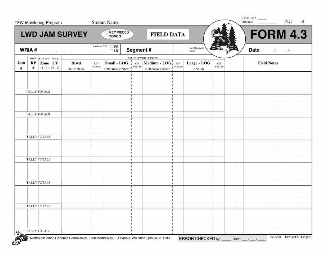
Page ___ of ___Stream NameCrew Lead _____Other(s) _____ _____
LWD JAM SURVEY FORM 4.3Date ______ / ______ / __________WRIA # ___ ___ . ___ ___ ___ ___ ___ ___ ___
RBLB Segment # __________ ______
Sub-SegmentCode
Unlisted Trib
TFW Monitoring Program
Northwest Indian Fisheries Commission, 6730 Martin Way E., Olympia, WA 98516 (360)438-1180 ERROR CHECKED by: _____ Date: ___ / ___ / ____ forms\99\F4-3.p65
FIELD DATA
Jam#
Field NotesZone(1 - 3)
LOWEST
FF(Y - N)
POOLDWN
RP#
○○○○○○○○○○○○○○○○○○○○
○○○○○○○○○○○○○○○○○○○○
KEY PIECESZONE 3
TALLY OF VISIBLE PIECES
RtwdDia ≥ 20 cm
KEYPIECES
Small - LOG≥ 10 cm to < 20 cm
KEYPIECES
Medium - LOG≥ 20 cm to < 50 cm
KEYPIECES
Large - LOG≥ 50 cm
KEYPIECES
TALLY TOTALS
○○○○○○○○○○○○○○○○○○○○
○○○○○○○○○○○○○○○○○○○○
○○○○○○○○○○○○○○○○○○○○
TALLY TOTALS
○○○○○○○○○○○○○○○○○○○○
○○○○○○○○○○○○○○○○○○○○
○○○○○○○○○○○○○○○○○○○○
TALLY TOTALS
○○○○○○○○○○○○○○○○○○○○
○○○○○○○○○○○○○○○○○○○○
○○○○○○○○○○○○○○○○○○○○
TALLY TOTALS
○○○○○○○○○○○○○○○○○○○○
○○○○○○○○○○○○○○○○○○○○
○○○○○○○○○○○○○○○○○○○○
TALLY TOTALS
○○○○○○○○○○○○○○○○○○○○
○○○○○○○○○○○○○○○○○○○○
○○○○○○○○○○○○○○○○○○○○
TALLY TOTALS
○○○○○○○○○○○○○○○○○○○○
○○○○○○○○○○○○○○○○○○○○
○○○○○○○○○○○○○○○○○○○○
TALLY TOTALS
○○○○○○○○○○○○○○○○○○○○
3/18/99

Appendix B
Completed Examples ofForms 4.0, 4.1, 4.2, and 4.3
TFW Monitoring Program - June 1999
Large Woody Debris Survey


Appendix C
LWD Criteria & Code Field Sheet Copy Master
(Keep original copy master with manual)
TFW Monitoring Program - June 1999
Large Woody Debris Survey

TFW Monitoring Program - June 1999
Errata 7/7/99

TFW Monitoring Program - June 1999
Errata 7/7/99

Appendix D
Standard Field and Vehicle Gear Checklist Copy Master(Keep original copy master with manual)
TFW Monitoring Program - June 1999
Large Woody Debris Survey

TFW Monitoring Program - June 1999
Large Woody Debris Survey
Appendix D
[ STANDARD FIELD GEAR
� Field clip board/form holder� Survey Forms (on waterproof paper)� Copy of survey methods� Maps- topographic and road� Pencils & erasers� Permanent ink marker� Calculator� 150 mm ruler� Pocket field notebook
� Survey Vest� Compass� Safety whistle� Spring clips (2)� Vinyl flagging� Pocket knife/multi-purpose tool
� Backpack or canvas tote bag� First aid kit� Water bottle and/or filtration system� Food/energy bars� Rain gear� Leather gloves� Safety glasses� Bug repellant� Sun screen� Small flashlight or headlamp� Matches/fire starter� Emergency blanket� Snake bite kit (eastern Washington)
[ STANDARD VEHICLE GEAR
� Waterproof plastic tote box� Backup fiberglass tape� Comprehensive first aid kit� Rain tarp� Rope (100 ft.)� Extra water� Extra food� Extra dry clothes� Extra batteries� Spare tire/jack/tire iron� Tire sealant/inflater� Tow strap� Come-along winch� Fire shovel� Fire extinguisher� CB radio (to monitor logging activity)� Cell phone/VHF radio� Brush cutter� Ax/bow saw/chain saw� Tire chains
For remote work, extra survival & safetygear is recommended.
This gear list is provided as a guideline for outfittingfield crews and is not intended to cover all situations.Local conditions may require additional or differentgear.

Appendix E
Data Management Examples
TFW Monitoring Program - June 1999
Large Woody Debris Survey

TFW Monitoring Program - June 1999
Large Woody Debris Survey
APPENDIX EEXAMPLE: Excel Data Entry
Spreadsheet Fields
**Examples show column headers only for each type entry fileTFW MonitoringLWD Survey Header Form 4.0 lwdhd.xlswria basin wria stream trib segm sub segm begin survey
dateend survey
dateleader first
nameleader last
nameleader
affiliationrecorder first
namerecorder last
name
>>>>
recorder affiliation
begin ref pt end ref pt beginning river mile
(mi)
ending river mile (mi)
discharge 1 date
discharge 1 flow (cms)
disch 1 down ref pt
disch 1 dist above ref pt
(m)
discharge 2 date
discharge 2 flow (cms)
>>>>
disch 2 down ref pt
disch 2 dist above ref pt
(m)
discharge 3 date
discharge 3 flow (cms)
disch 3 down ref pt
disch 3 dist above ref pt
(m)
survey length (m)
survey coverage
survey percentage
(%)
field notes
TFW MonitoringLWD Level 1 Survey Data Form 4.1 lwd1data.xlswria basin wria stream trib segm sub segm beginning
survey datedownstr.
refptzone num zone
rtwads (>20 cm)
zone small logs (10-20
cm)
zone med logs (20-50
cm)
zone large logs (>50
cm)
>>>>
key rtwads (>20 cm)
key small logs (10-20
cm)
key med logs (20-50
cm)
key large logs (>50
cm)
field notes entry date
TFW MonitoringLWD Level 2 Survey Data Form 4.2 lwd2data.xlswria basin wria stream trib segm sub segm beginning
survey datepiece survey
datepiece num dwnstr ref pt piece type
(L/R)piece diam
(cm)zone1 length
(m)
>>>>
zone2 length (m)
zone3 length (m)
zone4 length (m)
wood type (C/D/U)
stability code 1
(R/B/P/U)
stability code 2
(R/B/P/U)
stability code 3
(R/B/P/U)
pool form func (Y/N)
orien-tation decay class decay subclass
>>>>
field notes entry date
TFW MonitoringLWD Jam Survey Data Form 4.3 lwdjdata.xlswria basin wria stream trib segm sub segm begin survey
datejam survey
datejam num dwnstr ref pt rtwads (>20
cm)small pieces (10-20 cm)
med pieces (20-50 cm)
>>>>
large pieces (>50 cm)
chan zone pool form func
key rtwads (>20 cm)
key small logs (10-20
cm)
key med logs (20-50
cm)
key large logs (>50
cm)
field notes entry date

Level 1 Large Woody Debris Survey ReportTFW Monitoring
Stream Name: GOLD CREEK WRIA: 39.1881
Survey Date: 08/31/1998 to 08/31/1998
100 / prtReference Points:
. 000
Segment: 1 sub: 0
0 7to
0.1 to 1.0River Miles: Johnny Grady
Svy Length (m)/Coverage:
Survey Leader:
Affiliation: USFSDate Discharge1 09/01/199823
Flow (cms)0.36
Total In-channel Piece Summary (Individual and Debris Jam Pieces)
Rootwads
Logs 10-20 cm
Logs 20-50 cm
Logs >50 cm
Total
Total # of Pieces
Percent of Total Pieces
LWD per Chan Width
LWD per Kilometer
Number of Key Pieces
Percent LWD Key Pieces
Key Pieces per Chan Width
Key Pieces per Kilometer
7 13.2% 0.0 70.0
12 22.6% 0.0 120.0
26 49.1% 0.0 260.0
8 15.1% 0.0 80.0
53 0.0 530.0
Channel Width: 0.00 meters on 08/31/1998
Individual Piece Summary
Total # of Pieces
Rootwads 7
Logs 10-20 cm 8
Logs 20-50 cm 23
Logs >50 cm 4
Total 42
Percent Zone 1 Pieces
Number Zone 1 Pieces
42.9%
62.5%
47.8%
3
5
11
0
19
0.0%
45.2%
Percent Zone 2 Pieces
Number Zone 2 Pieces
42.9%
25.0%
43.5%
18
75.0%
42.9%
3
2
10
3
Percent of Key Pieces
Number of Key Pieces
12/08/1999GOLD CREEK000.1881.39Page 1 of 2 Segm: 1 0

Level 1 Large Woody Debris Survey ReportTFW Monitoring
Debris Jam Summary
Number of Debris Jams Rootwads
Number Total Pieces
Number Key Pieces
Percent Key Pieces
Debris Jams per Kilometer
Logs >=10 <20 cm
Logs >=20 <50 cm
Logs >=50 cm
1 10.00 0 11 0 0.0%4 3 4
12/08/1999GOLD CREEK000.1881.39Page 2 of 2 Segm: 1 0

Level 2 Large Woody Debris Survey ReportTFW Monitoring
Stream Name: DEEP CREEK WRIA: 19 .0103 . 000
Survey Date: 08/24/1992 to 09/28/1992
0 to 41 4100 /
Segment: 1 sub: 0
0.1 to 2.6 RH
Svy Length (m)/Coverage:
Survey Leader:
Affiliation:Lower Elwha Tribe
Reference Points:
River Miles:Discharge Date Flow (cms)
123
Total In-channel Piece Summary (Individual and Debris Jam Pieces)
Number of Pieces
Percent of Total Pcs
LWD per Chan Width
LWD per Kilometer
# of Key Pieces
Prcnt LWD / Key Pieces
Key Pcs per Chan Width
Key Pieces per Kilometer
Rootwads 42 3.0% 0.2 10.2 1 20.0% 0.0 0.2Logs >=10 <20cm 485 34.1% 2.5 118.3 0 0.0% 0.0 0.0Logs >=20 <50cm 623 43.8% 3.2 152.0 0 0.0% 0.0 0.0
Logs >= 50cm 274 19.2% 1.4 66.8 4 80.0% 0.0 1.0
Total 1424 7.3 347.3100.0% 5 0.00.0 1.2
Number of Pieces
Mean Diam (cm)
Mean Len (m)
Total Vol (m3)
Mean Vol (m3)
Total In-Chan Vol
(m3)
Mean In-Chan Vol (m3)
In-Chan Vol/CW (m3)
In-Chan Vol/Km
Rootwads 42 62.3 2.0 35.09 0.84 35.09 0.84 0.18 8.56Logs >= 10 <20 cm 485 15.1 5.9 53.89 0.11 47.62 0.10 0.24 11.62Logs >= 20 <50 cm 623 32.2 6.4 349.75 0.56 300.98 0.48 1.54 73.41
Logs >= 50 cm 274 70.6 6.3 831.57 3.03 708.40 2.59 3.62 172.78
Total 1424 1270.30 0.89 1092.09 0.77 5.58 266.36
Debris Jam Summary
Number of Debris Jams Rootwads
Number Total Pieces
Number Key Pieces
Percent Key Pieces
Debris Jams per Kilometer
Logs >=10 <20 cm
Logs >=20 <50 cm
Logs >=50 cm
45 10.98 18 920 0 0.0%369 354 179
Channel Width: 20.95 meters on 08/24/1992
Segm: 12/08/19991DEEP CREEK000.0103.19Page 1 of 3 0

Level 2 Large Woody Debris Survey ReportTFW Monitoring
Individual In-channel LWD Piece Summary
Number of Pieces
Pieces per Chan Width
Pieces per Kilometer
Number of Key Pieces
Percent Key Pieces
Key Pieces per Chan Width
Key Pieces per Kilometer
All Pieces By Piece Type
Rootwads 24 0.12 5.9 20.0%1 0.20.005Logs 480 2.45 117.1 80.0%4 1.00.020
Total 504 2.58 122.9 5 1.20.026100.0%
Pieces By Size CategoryPieces per Chan Width
Pieces per Kilometer
Number of Key Pieces
Percent Key Pieces
Key Pieces per Chan Width
Key Pieces per Kilometer
Number of Pieces
Piece Category
Rootwads 24 0.12 5.9 1 20.0% 0.005 0.2 >=10 <20 cm 116 0.59 28.3 0 0.0% 0.000 0.0 >=20 <50 cm 269 1.37 65.6 0 0.0% 0.000 0.0
>=50 cm 95 0.49 23.2 4 80.0% 0.020 1.0
Individual In-channel LWD Volume SummaryAll Pieces by Piece Type
Mean Diam (cm)
Mean Len (m) Mean Vol (m3)
Total Vol (m3)
Mean In-Chan Vol (m3)
Total In-Chan Vol (m3)
In-Chan Vol/CW (m3)
In-Chan Vol/Km
Rootwads 62.3 2.0 0.84 20.05 0.10 4.8920.05 0.84
Logs 35.7 6.3 0.94 386.96 1.98 94.38452.23 0.81
Total 407.02 2.08 99.27472.28 0.77
Pieces By Size CategoryIn-Chan Vol/Km
Mean In-Chan Vol (m3)
Total In-Chan Vol (m3)
In-Chan Vol/CW (m3)
Mean Len (m)
Mean Vol (m3)
Total Vol (m3)
Mean Diam (cm)
Piece Category
Rootwads 0.10 4.8962.3 2.02 0.84 20.0520.05 0.84 >= 10 <20 cm 0.06 2.7815.1 5.93 0.11 11.3912.89 0.10 >= 20 <50 cm 0.66 31.7032.2 6.39 0.56 129.97151.02 0.48
>= 50 cm 1.26 59.9170.6 6.35 3.03 245.61288.32 2.59
Segm: 12/08/19991DEEP CREEK000.0103.19Page 2 of 3 0

Level 2 Large Woody Debris Survey ReportTFW Monitoring
Individual In-channel Piece Characteristics Summary
Num of Pieces
Prcnt of Total
Total Vol (m3)
In-Chan Vol (m3)
% Vol In-Chan
# Pcs / Stab Fact
% with Stab Fact
% / Root System
% total pcs with stability factors
% Part Buried % Pinned
% Form Pools
Conifer 185 36.7% 289.97 245.07 13.5%36.2%4.3%54.1%10084.5% 22.7%Deciduous 192 38.1% 138.08 119.14 14.6%24.0%13.0%51.6%9986.3% 8.9%
Unknown 127 25.2% 44.23 42.80 13.4%33.1%2.4%48.8%6296.8% 11.8%
Total 504 472.28 407.02 261 51.8% 7.1% 30.8% 13.9%86.2% 14.7%
Segm: 12/08/19991DEEP CREEK000.0103.19Page 3 of 3 0

Data Summary by Reference Point ReportTFW Monitoring
KENNEDY CREEK WRIA: 14 .0012 .000Segment: 8 sub: 0
Stream Name:
SQUAXIN ISLAND TRIBEAffiliation:STEVIEMICHELLESurvey Leader:
Survey Coverage:4.2to4River Miles:
300Survey Length:
RFP Survey Date:HAB Survey Date:LWD Survey Date:
10/03/199410/03/1994
10/03/1994 to 10/03/1994
Reference Point0 - 1 Multi-Chan% Closure
51Lft BnkDnstrRt Bnk
Canopy ClosureUpstr
Dist betweenRef Pts100 mtrs
BankWidth Depth7.20 0.250
Unit Type Total NumberPercentage
of TotalTotal Surface Area
(sq. meters)Percentage of Surface Area
Habitat Unit Summary
Cascades 21.10% 3.90%4 31.89Pools 31.60% 75.10%6 620.95Riffles 47.40% 21.10%9 174.51Tailouts 0.00% 0.00%0 0
Habitat Units per Kilometer:Habitat Units per Bankfull Width:
190.0
1.5
Other Unit Information
Unit Type Number Total Length
Obscured Units 0 0Subsurface Flow Units 0 0Wetland Units 0 0
Habitat Unit Location
Number of Units Total LengthUnit Category
Primary Units 11 109.10Secondary Units 5 32.10Side-channel Units 3 11.20
. 12/09/1999KENNEDY CREEKPage 1 of 6 000 Segm:14 . 0012 ,8 0

Data Summary by Reference Point ReportTFW Monitoring
Total Piece Summary (Individual and Debris Jam Pieces)
Number of Pieces
Percent of Total Pcs
LWD per Chan Width
LWD per Kilometer
# of Key Pieces
Prcnt LWD / Key Pieces
Key Pcs per Chan Width
Key Pieces per Kilometer
Rootwads 2 100.0% 0.16 20.0 0 0.00 0 0Logs >=10 <20cm 12 42.9% 0.98 120.0 0 0.00 0 0Logs >=20 <50cm 25 47.2% 2.03 250.0 0 0.00 0 0
Logs >= 50cm 13 81.3% 1.06 130.0 1 0.06 0.0813 10
Total 52 4.22 520.0 0.0813 100.061
Number of Pieces
Mean Diam (cm)
Mean Len (m)
Total Vol (m3)
Mean Vol (m3)
Total In-Chan Vol
(m3)
Mean In-Chan Vol (m3)
In-Chan Vol/CW (m3)
In-Chan Vol/Km
Rootwads 2 0.0 0.0 0.000 0.000 0.000 0.000 0.000 0.0Logs >= 10 <20 cm 12 14.8 3.6 0.734 0.061 0.424 0.035 0.034 4.2Logs >= 20 <50 cm 25 30.9 5.4 10.175 0.407 8.925 0.357 0.725 89.2
Logs >= 50 cm 13 64.5 5.9 29.358 2.258 7.489 0.576 0.609 74.9
Total 40.267 2.726 16.837 0.968 1.368 168.452
Debris Jam Summary
Number of Debris Jams
Debris Jams per Kilometer
Logs >=10 <20 cm
Logs >=20 <50 cm
Percent Key Pieces
Number Key Pieces
Number Total PiecesRootwads
Logs >=50 cm
2 20 8 17 0038211
. 12/09/1999KENNEDY CREEKPage 2 of 6 000 Segm:14 . 0012 ,8 0

Data Summary by Reference Point ReportTFW Monitoring
KENNEDY CREEK WRIA: 14 .0012 .000Segment: 8 sub: 0
Stream Name:
SQUAXIN ISLAND TRIBEAffiliation:STEVIEMICHELLESurvey Leader:
Survey Coverage:4.2to4River Miles:
300Survey Length:
RFP Survey Date:HAB Survey Date:LWD Survey Date:
10/03/199410/03/1994
10/03/1994 to 10/03/1994
Reference Point1 - 2 Multi-Chan% Closure
64Lft BnkDnstrRt Bnk
Canopy ClosureUpstr
Dist betweenRef Pts100 mtrs
BankWidth Depth8.20 0.190
Unit Type Total NumberPercentage
of TotalTotal Surface Area
(sq. meters)Percentage of Surface Area
Habitat Unit Summary
Cascades 16.70% 7.00%3 50.15Pools 38.90% 66.30%7 475.36Riffles 44.40% 26.70%8 191.64Tailouts 0.00% 0.00%0 0
Habitat Units per Kilometer:Habitat Units per Bankfull Width:
180.0
1.5
Other Unit Information
Unit Type Number Total Length
Obscured Units 0 0Subsurface Flow Units 0 0Wetland Units 0 0
Habitat Unit Location
Number of Units Total LengthUnit Category
Primary Units 12 142.90Secondary Units 4 28.90Side-channel Units 2 17.20
. 12/09/1999KENNEDY CREEKPage 3 of 6 000 Segm:14 . 0012 ,8 0

Data Summary by Reference Point ReportTFW Monitoring
Total Piece Summary (Individual and Debris Jam Pieces)
Number of Pieces
Percent of Total Pcs
LWD per Chan Width
LWD per Kilometer
# of Key Pieces
Prcnt LWD / Key Pieces
Key Pcs per Chan Width
Key Pieces per Kilometer
Rootwads 0 0.0% 0.00 0.0 0 0.00 0 0Logs >=10 <20cm 8 61.5% 0.65 80.0 0 0.00 0 0Logs >=20 <50cm 10 43.5% 0.81 100.0 0 0.00 0 0
Logs >= 50cm 5 100.0% 0.41 50.0 0 0.00 0 0
Total 23 1.87 230.0 0 00.000
Number of Pieces
Mean Diam (cm)
Mean Len (m)
Total Vol (m3)
Mean Vol (m3)
Total In-Chan Vol
(m3)
Mean In-Chan Vol (m3)
In-Chan Vol/CW (m3)
In-Chan Vol/Km
Rootwads 0 0.0 0.0 0.000 0.000 0.000 0.000 0.000 0.0Logs >= 10 <20 cm 8 16.3 6.5 1.076 0.134 0.251 0.031 0.020 2.5Logs >= 20 <50 cm 10 32.8 4.4 4.065 0.407 2.668 0.267 0.217 26.7
Logs >= 50 cm 5 68.5 5.6 9.622 1.924 8.090 1.618 0.657 80.9
Total 14.763 2.465 11.009 1.916 0.895 110.123
Debris Jam Summary
Number of Debris Jams
Debris Jams per Kilometer
Logs >=10 <20 cm
Logs >=20 <50 cm
Percent Key Pieces
Number Key Pieces
Number Total PiecesRootwads
Logs >=50 cm
1 10 4 5 001203
. 12/09/1999KENNEDY CREEKPage 4 of 6 000 Segm:14 . 0012 ,8 0
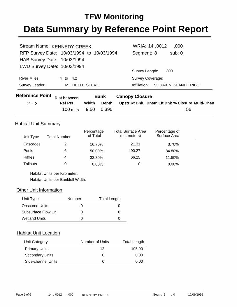
Data Summary by Reference Point ReportTFW Monitoring
KENNEDY CREEK WRIA: 14 .0012 .000Segment: 8 sub: 0
Stream Name:
SQUAXIN ISLAND TRIBEAffiliation:STEVIEMICHELLESurvey Leader:
Survey Coverage:4.2to4River Miles:
300Survey Length:
RFP Survey Date:HAB Survey Date:LWD Survey Date:
10/03/199410/03/1994
10/03/1994 to 10/03/1994
Reference Point2 - 3 Multi-Chan% Closure
56Lft BnkDnstrRt Bnk
Canopy ClosureUpstr
Dist betweenRef Pts100 mtrs
BankWidth Depth9.50 0.390
Unit Type Total NumberPercentage
of TotalTotal Surface Area
(sq. meters)Percentage of Surface Area
Habitat Unit Summary
Cascades 16.70% 3.70%2 21.31Pools 50.00% 84.80%6 490.27Riffles 33.30% 11.50%4 66.25Tailouts 0.00% 0.00%0 0
Habitat Units per Kilometer:Habitat Units per Bankfull Width:
Other Unit Information
Unit Type Number Total Length
Obscured Units 0 0Subsurface Flow Units 0 0Wetland Units 0 0
Habitat Unit Location
Number of Units Total LengthUnit Category
Primary Units 12 105.90Secondary Units 0 0.00Side-channel Units 0 0.00
. 12/09/1999KENNEDY CREEKPage 5 of 6 000 Segm:14 . 0012 ,8 0

Data Summary by Reference Point ReportTFW Monitoring
Total Piece Summary (Individual and Debris Jam Pieces)
Number of Pieces
Percent of Total Pcs
LWD per Chan Width
LWD per Kilometer
# of Key Pieces
Prcnt LWD / Key Pieces
Key Pcs per Chan Width
Key Pieces per Kilometer
Rootwads 2 8.7% 0.16 20.0
Logs >=10 <20cm 6 26.1% 0.49 60.0
Logs >=20 <50cm 11 47.8% 0.89 110.0
Logs >= 50cm 4 17.4% 0.33 40.0
Total 23 1.87 230.0 0 00.000
Number of Pieces
Mean Diam (cm)
Mean Len (m)
Total Vol (m3)
Mean Vol (m3)
Total In-Chan Vol
(m3)
Mean In-Chan Vol (m3)
In-Chan Vol/CW (m3)
In-Chan Vol/Km
Rootwads 2 99.0 2.4 3.464 1.732 3.464 1.732 0.281 34.6Logs >= 10 <20 cm 6 15.3 5.0 0.563 0.094 0.338 0.056 0.027 3.4Logs >= 20 <50 cm 11 28.6 4.7 4.028 0.366 1.980 0.180 0.161 19.8
Logs >= 50 cm 4 71.5 4.1 7.003 1.751 6.728 1.682 0.547 67.3
Total 15.058 3.943 12.509 3.650 1.016 125.123
. 12/09/1999KENNEDY CREEKPage 6 of 6 000 Segm:14 . 0012 ,8 0