Embed Size (px)
Citation preview

Ames Laboratory Publications Ames Laboratory
3-20-2006
Large magnetically induced strains inNi50Mn28.7Ga21.3 driven with collinear field andstressA. MallaOhio State University
M. J. DapinoIowa State University
Thomas A. LograssoIowa State University, [email protected]
Deborah L. SchlagelIowa State University, [email protected]
Follow this and additional works at: http://lib.dr.iastate.edu/ameslab_pubs
Part of the Condensed Matter Physics Commons, and the Metallurgy Commons
The complete bibliographic information for this item can be found at http://lib.dr.iastate.edu/ameslab_pubs/133. For information on how to cite this item, please visit http://lib.dr.iastate.edu/howtocite.html.
This Article is brought to you for free and open access by the Ames Laboratory at Iowa State University Digital Repository. It has been accepted forinclusion in Ames Laboratory Publications by an authorized administrator of Iowa State University Digital Repository. For more information, pleasecontact [email protected].

Large magnetically induced strains in Ni50Mn28.7Ga21.3 driven withcollinear field and stress
AbstractDespite the huge magnetic-field-induced strain (MFIS) of up to 9.5% exhibited by certain Ni–Mn–Ga alloys,their usefulness in applications is severely hindered by the electromagnet device needed for driving the alloyswith a magnetic field and orthogonal loading stress. In this paper we present macroscopic measurementsobtained from a single crystal of Ni50Mn28.7Ga21.3 which demonstrate a large reversible MFIS of −4100 ppmwhen the alloy is driven with quasistatic magnetic fields and fixed compressive stresses applied collinearlyalong the [001] axis. This collinear configuration marks a fundamental difference with prior research in thefield and points to the existence in this alloy of stable bias or residual stresses—likely associated with pinningsites in the alloy—which provide the energy necessary to restore the original variant state when the field isreversed. We present macroscopic magnetomechanical measurements which show a decrease of the MFISwith increasing stress loading and a stiffening of the alloy with increasing dc fields. The latter behavior isphenomenologically similar to the ΔE effect in magnetostrictive materials. The large reversible MFIS andtunable stiffness properties exhibited by this alloy could enable practical Ni–Mn–Ga actuators for high-deflection, low-force applications which due to being driven by a solenoid transducer are more compact,energy efficient, and faster than their electromagnet counterpart. A thermodynamic model is presented whichqualitatively characterizes the decay in MFIS with increasing compressive external load and provides a startingpoint for the characterization, design, and control of the proposed Ni–Mn–Ga devices.
Keywordsnickel alloys, manganese alloys, gallium alloys, magnetostriction, actuators, stress effects, internal stresses,elasticity, thermodynamics
DisciplinesCondensed Matter Physics | Metallurgy
CommentsThe following article appeared in Journal of Applied Physics 99 (2006): 063903 and may be found athttp://dx.doi.org/10.1063/1.2177927.
RightsCopyright 2006 American Institute of Physics. This article may be downloaded for personal use only. Anyother use requires prior permission of the author and the American Institute of Physics.
This article is available at Iowa State University Digital Repository: http://lib.dr.iastate.edu/ameslab_pubs/133

Large magnetically induced strains in Ni50Mn28.7Ga21.3 driven with collinearfield and stress
A. Malla and M. J. Dapinoa�
Department of Mechanical Engineering, The Ohio State University, Columbus, Ohio 43202
T. A. Lograsso and D. L. SchlagelAmes Laboratory, U.S. Department of Energy, Ames, Iowa 50011
�Received 18 July 2005; accepted 26 January 2006; published online 20 March 2006�
Despite the huge magnetic-field-induced strain �MFIS� of up to 9.5% exhibited by certain Ni–Mn–Ga alloys, their usefulness in applications is severely hindered by the electromagnet device neededfor driving the alloys with a magnetic field and orthogonal loading stress. In this paper we presentmacroscopic measurements obtained from a single crystal of Ni50Mn28.7Ga21.3 which demonstrate alarge reversible MFIS of −4100 ppm when the alloy is driven with quasistatic magnetic fields andfixed compressive stresses applied collinearly along the �001� axis. This collinear configurationmarks a fundamental difference with prior research in the field and points to the existence in thisalloy of stable bias or residual stresses—likely associated with pinning sites in the alloy—whichprovide the energy necessary to restore the original variant state when the field is reversed. Wepresent macroscopic magnetomechanical measurements which show a decrease of the MFIS withincreasing stress loading and a stiffening of the alloy with increasing dc fields. The latter behavioris phenomenologically similar to the �E effect in magnetostrictive materials. The large reversibleMFIS and tunable stiffness properties exhibited by this alloy could enable practical Ni–Mn–Gaactuators for high-deflection, low-force applications which due to being driven by a solenoidtransducer are more compact, energy efficient, and faster than their electromagnet counterpart. Athermodynamic model is presented which qualitatively characterizes the decay in MFIS withincreasing compressive external load and provides a starting point for the characterization, design,and control of the proposed Ni–Mn–Ga devices. © 2006 American Institute of Physics.�DOI: 10.1063/1.2177927�
I. INTRODUCTION
Ferromagnetic shape memory �FSM� refers to the re-versible deformations exhibited by a martensitic materialcaused by either martensitic variant reorientation or austeniteto martensite transformation in response to magnetic fields.In the Heusler alloy Ni2MnGa, cooling below the character-istic martensite start temperature Ms produces a cubic to te-tragonal transformation and a corresponding twin-variantstructure. Over a certain compositional range, a typical mar-tensite microstructure consists of a mixture of three variants,each with tetragonal lattice c�c�a �c /a=0.94�, in whichadjacent variants are separated by a boundary known as atwin plane.1 Large magnetic-field-induced strain �MFIS� re-sults from the reorientation of favorable martensite variantsthrough the motion of twin boundaries. Extensional room-temperature strains of 6% have been reported by Murray etal.2 The largest FSM deformations to date, of about 9.5%,have been obtained in orthorhombic seven-layered alloys.3
In Ni–Mn–Ga, the pseudoelasticity associated with thereorientation of twin variants takes place solely in the low-temperature martensitic phase and is driven by magneticfields or stresses. Since both magnetic fields and compressivestresses favor alignment of the short c axis of the tetragonal
unit cell, a fixed stress or magnetic field oriented perpendicu-lar to the drive field must be applied to restore the twinvariants and obtain reversible MFIS when the drive field iscycled. In applications, this is often done by placing a rect-angular alloy in an electromagnet with the drive field appliedalong the �110� direction and the load axis oriented along the�001� direction—both directions relative to the parent auste-nite phase. This perpendicular configuration is shown in Fig.1�a�. Electromagnets tend to be bulky and heavy in additionto having low energy density due to the high reluctance ofthe air gap and low frequency bandwidth due to large eddycurrent losses. This implies that despite the huge strain po-tential of Ni–Mn–Ga, practical actuators and sensors basedon these alloys are unfeasible due to the performance con-straints imposed by electromagnets.
We are interested in the MFIS of Ni–Mn–Ga along the�001� direction with fields applied along the same direction.This collinear configuration presents the critical advantagethat it allows to drive the alloy with a solenoid transducerlike that shown in Fig. 1�b�. This transducer architecture in-cludes a path for flux return and is thus significantly morecompact, lightweight, and energy efficient than its electro-magnet counterpart. Despite the apparent absence of amechanism in the collinear configuration to restore the vari-ant structure upon reversal of the field, experimental resultshave been published which show that moderate reversibledeformations are possible in Ni–Mn–Ga driven in this man-
a�Author to whom correspondence should be addressed; electronic mail:[email protected]
JOURNAL OF APPLIED PHYSICS 99, 063903 �2006�
0021-8979/2006/99�6�/063903/9/$23.00 © 2006 American Institute of Physics99, 063903-1
Downloaded 21 Mar 2006 to 147.155.1.86. Redistribution subject to AIP license or copyright, see http://jap.aip.org/jap/copyright.jsp
ner. These results point to additional strain mechanisms notfully accounted for by existing theory.
Wu et al.4 have reported a large recoverable MFIS of−3100 ppm in the �001� direction of an off-stoichiometrysingle crystal of Ni52Mn22.2Ga25.8 driven by a 20 kOe fieldalong the �001� direction. This alloy showed a martensiticself-strain of 2%, about a hundred times as large as that ofNi2MnGa, thus suggesting that the martensite variants in alarge fraction of the alloy are preferentially oriented. Thisreduces the degree of self-accommodation and leads to re-duced deformations compared with the 6% strains achievableby reorientation of the c axis throughout the alloy. The mea-sured deformations are very significant, nonetheless, as theycompare favorably with those of Terfenol-D. However, thecombination of high fields and low martensitic transforma-tion temperature, which in this alloy is situated slightly be-low room temperature, precludes the practical implementa-tion of this alloy in motion generation systems. Ohmic andeddy current heating produced within the solenoid transducerwould easily cause the alloy to transform to its austeniticphase.
In this paper, we report large reversible strains of−4100 ppm along the �001� direction of a cylindricalNi50Mn28.7Ga21.3 single-crystal rod driven with a sinusoidalmagnetic field applied along the same direction and no ex-ternal restoring force. We also present strain versus magneticfield curves obtained under varied compressive stresses ap-plied along the field direction. These magnetomechanicaltests are complemented by strain versus stress curves mea-sured under varied dc bias fields, which are used to establishthe dependence of elastic modulus with stress and field. Theresults show a stiffening of the alloy with increasing dc fieldsin a manner which is phenomenologically similar to the �Eeffect in rare-earth–iron compounds.5 The measurementswere performed at room temperature on the alloy as cast, thatis, without thermal, magnetic, or stress treatments. While inthe experiments by Wu et al.4 repeated cycling of the fieldwas necessary to achieve repeatable strains, the MFIS exhib-ited by our sample has remained invariant despite exposureof the alloy to a large number of field and stress cycles.These unexpected results cannot be explained by the currentmodels for twin-variant reorientation in Ni–Mn–Ga—based
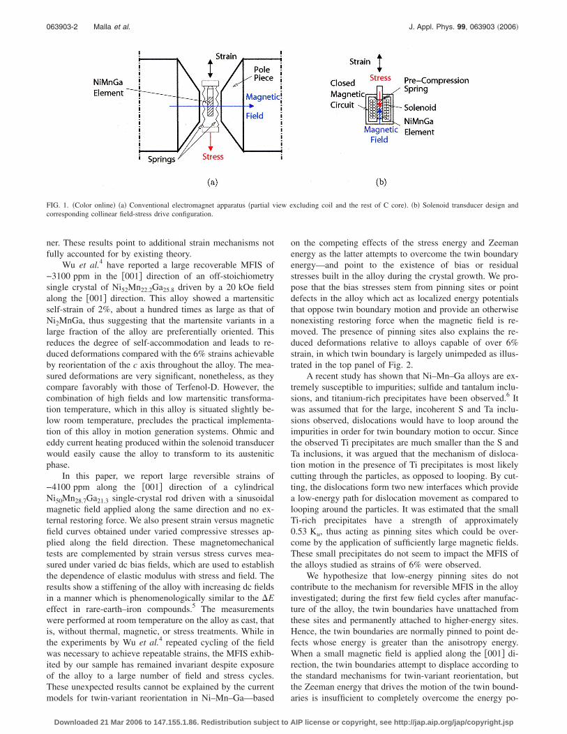
on the competing effects of the stress energy and Zeemanenergy as the latter attempts to overcome the twin boundaryenergy—and point to the existence of bias or residualstresses built in the alloy during the crystal growth. We pro-pose that the bias stresses stem from pinning sites or pointdefects in the alloy which act as localized energy potentialsthat oppose twin boundary motion and provide an otherwisenonexisting restoring force when the magnetic field is re-moved. The presence of pinning sites also explains the re-duced deformations relative to alloys capable of over 6%strain, in which twin boundary is largely unimpeded as illus-trated in the top panel of Fig. 2.
A recent study has shown that Ni–Mn–Ga alloys are ex-tremely susceptible to impurities; sulfide and tantalum inclu-sions, and titanium-rich precipitates have been observed.6 Itwas assumed that for the large, incoherent S and Ta inclu-sions observed, dislocations would have to loop around theimpurities in order for twin boundary motion to occur. Sincethe observed Ti precipitates are much smaller than the S andTa inclusions, it was argued that the mechanism of disloca-tion motion in the presence of Ti precipitates is most likelycutting through the particles, as opposed to looping. By cut-ting, the dislocations form two new interfaces which providea low-energy path for dislocation movement as compared tolooping around the particles. It was estimated that the smallTi-rich precipitates have a strength of approximately0.53 Ku, thus acting as pinning sites which could be over-come by the application of sufficiently large magnetic fields.These small precipitates do not seem to impact the MFIS ofthe alloys studied as strains of 6% were observed.
We hypothesize that low-energy pinning sites do notcontribute to the mechanism for reversible MFIS in the alloyinvestigated; during the first few field cycles after manufac-ture of the alloy, the twin boundaries have unattached fromthese sites and permanently attached to higher-energy sites.Hence, the twin boundaries are normally pinned to point de-fects whose energy is greater than the anisotropy energy.When a small magnetic field is applied along the �001� di-rection, the twin boundaries attempt to displace according tothe standard mechanisms for twin-variant reorientation, butthe Zeeman energy that drives the motion of the twin bound-aries is insufficient to completely overcome the energy po-
FIG. 1. �Color online� �a� Conventional electromagnet apparatus �partial view excluding coil and the rest of C core�. �b� Solenoid transducer design andcorresponding collinear field-stress drive configuration.
063903-2 Malla et al. J. Appl. Phys. 99, 063903 �2006�
Downloaded 21 Mar 2006 to 147.155.1.86. Redistribution subject to AIP license or copyright, see http://jap.aip.org/jap/copyright.jsp
tential of the pinning sites. Instead, the twin boundaries looparound the impurities and as they do work against the pin-ning sites, energy is dissipated. Saturation is achieved whenthe Zeeman energy is large enough to overcome the aniso-tropy energy and the magnetic moments become alignedwith the field without changing the orientation of the crystal.When the field is removed, the anisotropy energy returns themagnetic moments to the easy c axis of the crystal and thepinning site energy provides a restoring mechanism for thetwin boundaries, returning the sample to its original lengthand magnetization value. The pinning energy can thus beinterpreted as an internal bias stress field oriented perpen-dicular to the �001� direction, as shown in the bottom panelof Fig. 2. The internal bias stress can thus be approximatedas the applied stress for which twin boundary mobility iszero. This also implies that excessive pinning energy willrender the alloy inactive as the available Zeeman pressure isinsufficient to drive the motion of twin boundaries awayfrom the pinning sites.
II. EXPERIMENTS
A. Material preparation
A nonstoichiometric Ni–Mn–Ga rod measuring 6.35 mmin diameter by 22.43 mm in length with chemical composi-tion �wt %� Ni50Mn28.7Ga21.3 was used in the measurementspresented here. The rod was prepared as follows: appropriatequantities of high purity nickel, manganese, and galliumwere cleaned and arc-melted several times under an argonatmosphere. The buttons were remelted and the alloy dropcast into a chilled copper mold to ensure compositional ho-mogeneity throughout the ingot. The crystal was grown fromthe as-cast ingot in an alumina Bridgman style cruciblewhich was heated to 1350 °C under a pressure of 1.3�10−4 Pa to degas the crucible and charge. After melting,the chamber was backfilled to a pressure of 2.76�105 Pawith high purity argon to eliminate gas pockets and to mini-
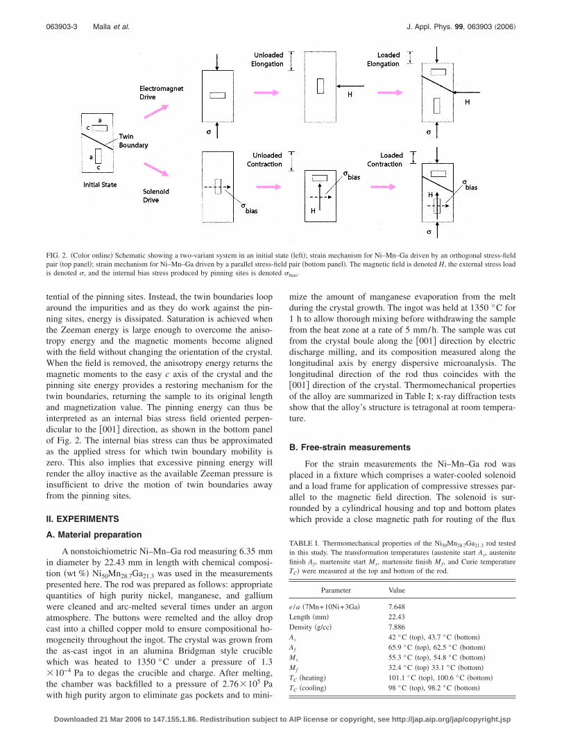
mize the amount of manganese evaporation from the meltduring the crystal growth. The ingot was held at 1350 °C for1 h to allow thorough mixing before withdrawing the samplefrom the heat zone at a rate of 5 mm/h. The sample was cutfrom the crystal boule along the �001� direction by electricdischarge milling, and its composition measured along thelongitudinal axis by energy dispersive microanalysis. Thelongitudinal direction of the rod thus coincides with the�001� direction of the crystal. Thermomechanical propertiesof the alloy are summarized in Table I; x-ray diffraction testsshow that the alloy’s structure is tetragonal at room tempera-ture.
B. Free-strain measurements
For the strain measurements the Ni–Mn–Ga rod wasplaced in a fixture which comprises a water-cooled solenoidand a load frame for application of compressive stresses par-allel to the magnetic field direction. The solenoid is sur-rounded by a cylindrical housing and top and bottom plateswhich provide a close magnetic path for routing of the flux
FIG. 2. �Color online� Schematic showing a two-variant system in an initial state �left�; strain mechanism for Ni–Mn–Ga driven by an orthogonal stress-fieldpair �top panel�; strain mechanism for Ni–Mn–Ga driven by a parallel stress-field pair �bottom panel�. The magnetic field is denoted H, the external stress loadis denoted �, and the internal bias stress produced by pinning sites is denoted �bias.
TABLE I. Thermomechanical properties of the Ni50Mn28.7Ga21.3 rod testedin this study. The transformation temperatures �austenite start As, austenitefinish Af, martensite start Ms, martensite finish Mf, and Curie temperatureTC� were measured at the top and bottom of the rod.
Parameter Value
e /a �7Mn+10Ni+3Ga� 7.648Length �mm� 22.43Density �g/cc� 7.886As 42 °C �top�, 43.7 °C �bottom�Af 65.9 °C �top�, 62.5 °C �bottom�Ms 55.3 °C �top�, 54.8 °C �bottom�Mf 32.4 °C �top� 33.1 °C �bottom�TC �heating� 101.1 °C �top�, 100.6 °C �bottom�TC �cooling� 98 °C �top�, 98.2 °C �bottom�
063903-3 Malla et al. J. Appl. Phys. 99, 063903 �2006�
Downloaded 21 Mar 2006 to 147.155.1.86. Redistribution subject to AIP license or copyright, see http://jap.aip.org/jap/copyright.jsp

into the rod �Fig. 3�. The MFIS was measured with a linearvariable differential transducer �LVDT� and strain gages.Since the sample is shorter than the height of the solenoid,AISI 1144 steel rods of equal length were waxed to the topand bottom of the sample, for both positioning the samplesymmetrically at the center of the solenoid and aiding in theclosing of the magnetic flux. Compressive loading was ap-plied through an AISI 1144 pushrod which is connected tothe loading cross bar with a nonmagnetic stainless steel rodfor magnetic isolation between the solenoid and load frame.The pushrod slides in a precision linear bearing.
The alternating magnetic field had an amplitude of up to725 kA/m and a frequency of 0.1 Hz. Mapping of the fieldalong the length of the solenoid was conducted with a Hallsensor and through finite element calculations. Because Ni–Mn–Ga is mechanically soft, magnetic forces acting on thepushrod were quantified and their effect subtracted from themeasured deformations in order to accurately quantify theMFIS produced by the Ni50Mn28.7Ga21.3 rod. Furthermore,the magnetostriction of the steel components was quantifiedand correspondingly subtracted from the measured deforma-tions.
The solid line in Fig. 4 shows the MFIS measured by astrain gage oriented parallel to the �001� direction with zeroapplied stress. A maximum compressive strain of −4100 ppmwas obtained; the contraction of the rod is consistent with therotation of the c axis toward the �001� direction. Independentconfirmation of this result was conducted at Iowa StateUniversity7 �ISU� and Naval Surface Warfare Center�NSWC�.8 The triangles in Fig. 4 show the ISU measure-ment, in which the Ni50Mn28.7Ga21.3 rod was strain gaged andplaced longitudinally between the poles of an electromagnet.Excellent agreement with our measurements is observed.
For the NSWC tests, the change in length of the rodunder zero stress was measured. A static magnetic field of560 kA/m was applied transverse to the rod direction andparallel to the rod direction by means of an electromagnet.The rod was located on a pole face and kept in place by astyrofoam holder. The length of the rod was measured with acaliper at zero field after application of a transverse field andsubsequently at zero field after application of a longitudinalfield. The measured fractional change of length is
−4000 ppm, which is consistent with our results since theapplied field was lower than in our measurements.
C. Magnetomechanical tests
Strain versus field curves at various fixed compressivestresses are shown in Fig. 5. The stresses were applied bymeans of dead weights for a total stress range of0–58.23 MPa. For clarity, the measurements are shown intwo panels, �a� and �b�, which, respectively, show the rangesof 0.13–5.63 MPa and 7.03–19.69 MPa. Since both the ex-ternal stress and applied magnetic field favor alignment ofthe variants with the c axis aligned along the longitudinal rodaxis, the volume available for reorientation of variants bymagnetic field and associated MFIS decrease with increasingexternal stress. Further, the MFIS beyond a certain stresslimit becomes negligible and only magnetostriction ispresent. This behavior is illustrated for the complete range ofstresses investigated in Fig. 6, where the abscissa representsthe maximum MFIS obtained at a given stress value. Overthis range of stresses, the maximum MFIS becomes stable atapproximately −150 ppm for compressions greater than19 MPa.
Compression cycles conducted at various static magneticfields ranging between 0 and 378 kA/m are shown in Fig. 7.Each curve was obtained by applying a constant magneticfield and subsequently applying a cyclic compressive stresswith amplitude of 13.36 MPa. Each curve is thus shiftedrelative to the line of zero strain by an amount equal to thecompressive MFIS produced by the given magnetic field.After completion of a given compression cycle, the field wasincremented to the value used on the next compression cyclewithout resetting the strain. Figure 7 reflects the nonlinearand hysteretic dependence between stress and strain for thisalloy. The amount of hysteresis decreases with increasingfield and a saturation effect is observed since as the field isincreased, the available MFIS decreases as the volume ofvariants available for reorientation decreases. Nonclosure ofthe cycles is observed which is due to the remanent magne-
FIG. 3. �Color online� Schematic representation of the solenoid apparatusemployed in this study.
FIG. 4. �Color online� Solid line: MFIS measured in the �001� direction asa function of the magnetic field applied along the same direction. The tri-angles represent measurements conducted at Iowa State University on thesame rod under similar conditions but employing an electromagnet.
063903-4 Malla et al. J. Appl. Phys. 99, 063903 �2006�
Downloaded 21 Mar 2006 to 147.155.1.86. Redistribution subject to AIP license or copyright, see http://jap.aip.org/jap/copyright.jsp

tization producing a certain amount of compression after re-moval of the field. The nonclosure decreases with increasingstatic field.
The data also suggest a strong magnetoelastic couplingwhich phenomenologically behaves closer to the coupling in
Terfenol-D �Ref. 9� than that associated with shape memoryand magnetic pseudoelasticity.10 To further illustrate thiscoupling, we show in Fig. 8 data extracted from Fig. 7 wherefor clarity only the loading portion of the compression cyclesis shown, the strain offsets have been removed, and the ab-scissa and ordinate have been swapped. These curves suggestan overall stiffening with increasing dc field, consistent withthe field-induced stiffening measured dynamically by Faidleyet al.11 As a bias magnetic field is applied, the stiffer variantswith the short c axis aligned with the field are favored andgrow by twin boundary motion. Since in Ni–Mn–Ga themagnetization of the unit cell is rigidly attached to the c axis,this selective alignment biases the initial magnetization to-wards the saturated state and produces a decrease in theMFIS possible by twin boundary motion. Cullity12 hasshown that the amount of additional strain beyond the elasticstrain is directly related to the decrease in elastic modulusfrom that of the material when only elastic strain is possible,often referred to as the �E effect. To illustrate this effect in
FIG. 5. �Color online� Strain vs magnetic field as a function of stress: rangeof 0–5.63 MPa �bottom� and range of 7.03–19.69 MPa �top�.
FIG. 6. �Color online� Maximum MFIS vs applied stress.
FIG. 7. �Color online� Strain-stress cycles at different static field values.After completion of a given compression cycle, the field was incremented tothe value used on the next compression cycle without resetting the strain.
FIG. 8. �Color online� Loading curves at different dc magnetic field values.
063903-5 Malla et al. J. Appl. Phys. 99, 063903 �2006�
Downloaded 21 Mar 2006 to 147.155.1.86. Redistribution subject to AIP license or copyright, see http://jap.aip.org/jap/copyright.jsp

Ni–Mn–Ga driven with a collinear field and stress, the de-pendence of the elastic modulus with stress and field, calcu-lated from Fig. 8, is shown in Figs. 9 and 10, respectively.
D. Magnetization measurements
The magnetization was measured with a pickup coilwound on an aluminum spool which surrounds the Ni–Mn–Ga rod. Saturation magnetization was measured at381 kA/m. The coercive field is very low at about8.8 kA/m, while the remanent magnetization has a value of183 kA/m, corresponding to 0.23 T. For stresses up to58 MPa, the magnetization curve is observed to not changeas a function of stress.
III. THEORY
We are interested in characterizing the MFIS as a func-tion of magnetic fields and applied stresses. To that end, we
consider a simplified two-variant system, shown in Fig. 11,and the corresponding Gibbs free energy which is written asa function of the Zeeman energy difference between the vari-ants, the stress energy and the energy of the boundary. Vari-ant 2 has a volume fraction of � and is that which has the caxis aligned with the axial magnetic field Hy. Variant 1 is thetransverse variant with magnetization vectors oriented in thec axis and has a volume fraction of �1−��. This construct hasbeen detailed by Faidley et al.13 on the basis of thermody-namic considerations in the manner of Kiefer andLagoudas14,15 and Hirsinger and Lexcellent.16 The systemcan thus be treated as a mixture of variants with scalar freeenergy,
G��y,Hy,T� = �1 − ��G1 + �G2 + Gb, �1�
where Gi is the energy of the ith variant and Gb is the energyof the boundary between the two variants. In order to writeexpressions for Gi, it is assumed that �a� the system is iso-thermal and �b� the fields are large enough to ensure that theeffects of the magnetic domains can be ignored. In this casethe expression for the energy of each variant is given by astandard expression for the Gibbs free energy,17
Gi��y,Hy� = �i −1
2��ySyy
i �y −�0
�MiHy , �2�
where �i, Syyi , and Mi, respectively, denote the Helmholtz
energy, mechanical compliance, and magnetization of the ithvariant, �y is the applied stress, � is the density, and �0 is thepermeability of free space. The Gibbs free energy of eachvariant is equal to the Helmholtz energy minus the elasticand Zeeman energies.
The energy of the twin boundary stems from twosources. The first is the energy necessary to rotate a unit cell,which can be expressed as work done to overcome a force;the second is the energy of the pinning sites, which can bemodeled as that of a mechanical spring. Thus the boundaryenergy term has the form
FIG. 9. �Color online� Variation in elastic modulus with compressive stressat different dc field values.
FIG. 10. �Color online� Variation in elastic modulus with dc magnetic fieldat different compressive stresses. The markers indicate the measured datawhile the lines are polynomial fits to the data.
FIG. 11. Twin martensite variants in a Ni–Mn–Ga alloy subjected to collin-ear magnetic fields Hy and stresses �y.
063903-6 Malla et al. J. Appl. Phys. 99, 063903 �2006�
Downloaded 21 Mar 2006 to 147.155.1.86. Redistribution subject to AIP license or copyright, see http://jap.aip.org/jap/copyright.jsp

Gb =�c1� + k1�2, � � 0
c2� + k2�2, � 0,� �3�
where ki �i=1,2� is the effective spring constant of the pin-ning sites, ci �i=1,2� is the force associated with cell reori-entation, and the two branches of the function occur becausethe material behavior is not the same when the field is in-creasing and variant 2 is growing as it is when the field isdecreasing and variant 2 is shrinking.
Substitution of �2� and �3� into �1� yields
G��y,Hy� = �i −1
2�Syy
1 �y2 + ��−
1
2��Syy�y
2 −�0Ms
�Hy�
+�c1� + k1�2, � � 0
c2� + k2�2, � 0,� �4�
where the � operator refers to the difference between the twovariants and ��=0 since the Helmholtz energies of the twovariants are identical. To establish a condition for the onsetof twin-variant motion, we consider a thermodynamic driv-ing force � as proposed for ferromagnetic shape memorymaterials by Kiefer and Lagoudas,14
� = �s�y − ��G
��, �5�
where �s is the saturation strain. The condition is obtained byconsidering the energy balance between the thermodynamicforce driving the motion of the twin boundary and the energydissipated during the motion,
� = ± Y�, �6�
with Y� a positive quantity representing the dissipation ofenergy. The plus sign represents the reorientation of variant 2into variant 1 and the minus sign represents the oppositecase.
Differentiation of �4� and substitution into �5� yields theforce balance
±Y� = �s�y −1
2�Syy�y
2 − �0MsHy
− ��c1 + 2k1� , � � 0
c2 + 2k2� , � 0.� �7�
Expression �7� can then be solved for the volume fraction,
� =�1/�2�k1���s�y + 12�Syy�y
2 + �0MsHy − �c1 − Y�� , � � 0
1/�2�k2���s�y + 12�Syy�y
2 + �0MsHy − �c2 + Y�� , � 0,� �8�
which is dependent on the applied field Hy and axial stress �y. To facilitate the numerical implementation, expression �8� isrewritten as
� = A1��s�y + 12�Syy�y
2 + �0MsHy − �c1 − Y�� , H � 0 and � �s
�s, � � �s
A2��s�y + 12�Syy�y
2 + �0MsHy − �c2 + Y�� , H 0 and � �s, �9�
where A1=1/ �2�k1�, A2=1/ �2�k2�, and �s is the saturationvolume fraction. The strain is related to the volume fractionby
� = ��th, �10�
with �th the maximum theoretical strain which would occur ifa single boundary swept through the entire material, henceproducing a change in � from 0 to 1. Hence, for the casewhere the twin boundaries are restrained by pinning sites, �will be limited to a much smaller range.
Parameters that need to be identified in this model in-clude k1, k2, �s, �Syy, Ms, c1, c2, and Y�. Parameters �Syy,Ms, and Y� were obtained from published data.14 The remain-ing parameters were determined phenomenologically by fit-ting of strain versus magnetic field data at a particular ap-plied stress �p. As shown in Fig. 12, three data pointsprovide the following information: �i� field H1 at the strainturn around point, �ii� strain �2 at the crossover point, �iii�field H3 at the onset of saturation, and �iv� saturation strain
�s. Using these measurements, the equations in Table II canbe used to calculate the parameters needed to implement re-lations �9� and �10�.13 Model results for various compressive
FIG. 12. �Color online� Data points used for identification of modelparameters.
063903-7 Malla et al. J. Appl. Phys. 99, 063903 �2006�
Downloaded 21 Mar 2006 to 147.155.1.86. Redistribution subject to AIP license or copyright, see http://jap.aip.org/jap/copyright.jsp

strains are shown in Fig. 13, where it is noted that the modeladequately characterizes the decay in maximum MFIS withincreasing external load. Table II shows the model param-eters employed in Fig. 13; further details regarding the nu-merical implementation of the model are given by Faidley etal.13
IV. DISCUSSION
This paper presents macroscopic measurements on themagnetomechanical behavior of a single crystal ofNi50Mn28.7Ga21.3 driven with alternating magnetic fields andfixed compressive stresses applied along the �001� axis. Thiscollinear field-stress drive configuration marks a fundamen-tal difference with prior research on Ni–Mn–Ga alloys,which is largely based on orthogonal field-stress or field-fieldconfigurations in accordance with current theory for marten-site variant reorientation. According to theory, reversibleMFIS would not be possible in Ni–Mn–Ga driven in themanner examined in this investigation since both the mag-netic field and stress favor the same variant. The measure-ments therefore point to an internal source of energy which
restores the original variant state upon reversal of the fielddirection. Since the reversible responses were measured onthe alloy as cast and they have persisted after a large numberof field and stress cycles, the internal restoring energy isattributed to high-energy pinning sites formed during manu-facture of the alloy. The twin boundaries remain attached tohigh-energy pinning sites and loop around them under theaction of magnetic fields or stresses.
The unloaded measurements show a large reversibleMFIS of −4100 ppm. The measurements under increasingcompressive stress indicate that in this alloy the maximumMFIS decays rapidly relative to the unloaded deformationand becomes stable at approximately −150 ppm for compres-sions greater than 19 MPa. The decay in MFIS is expectedsince mechanical loads collinear with the magnetic field pro-mote the growth of variants with the c axis oriented with thefield and reduce the volume available for reorientation ofvariants by magnetic field. Considering that the externalstress and applied magnetic field promote looping of the twinboundaries around pinning sites and the internal bias stressopposes the looping, when the applied elastic and Zeemanenergies equal the pinning energy—which in the presentedmodel is assumed to be part of the boundary energy—thetwin boundaries become immobilized and no more MFIS ispossible. Beyond a certain stress limit the MFIS becomesnegligible and only magnetostriction is present, as observedin Fig. 6. This stress limit provides a measure of the strengthof the internal bias stress, but the exact determination of theinternal bias stress requires knowledge of the initial configu-ration of variants in the alloy and how the configuration hasbeen changed by the applied stress. In Fig. 7 the stress-straincurve at zero field is reversible even beyond the initial elasticregion and when the alloy is in its quasiplastic region. Thisbehavior is attributed to the internal bias stress which re-stores the initial configuration of the variants.
The ability of the studied alloy to do mechanical workagainst external loads is unsatisfactory for high-power actua-tor design, which is not unexpected since previous studieshave shown that Ni–Mn–Ga alloys exhibit low blockingstresses.18 Notwithstanding, the strains of −4100 ppm repre-sent over a twofold improvement over Terfenol-D, the mosttechnologically advanced magnetostrictive material. Thislarge MFIS could enable practical Ni–Mn–Ga actuators forhigh-deflection, low-force applications. It is emphasized thatsolenoid actuators are more compact, energy efficient, andfaster than is possible to achieve through the conventionalperpendicular field-stress drive configuration and mandatoryelectromagnet-based magnetic circuit. Furthermore, the abil-ity to change the stiffness with dc fields can potentially leadto Ni–Mn–Ga tunable vibration absorbers and delay lines forunderwater communications.
The model qualitatively characterizes the decay in MFISwith increasing compressive load. Because of its phenom-enological nature, however, further work is needed for im-proving its physical fidelity and accuracy. To that end, furthercharacterization by investigating the microstructural proper-ties of the alloy will be necessary for determining the exactphysical origin of the pinning sites. The formation of pinningsites during manufacture also hints at the possibility of de-
TABLE II. Summary of model parameters employed in Fig. 13.
�Syy =0
Ms=0.622 MA/mY�=0.2�106 J�th=−0.06k1=1.5 k2
k2 =�0MsH3�th
2��s − �2�
c1 = �s�p +1
2�Syy�p
2 + �0MsH1 − Y�
c2 = �s�p +1
2�Syy�p
2 + Y� − 2k2�2
�th
FIG. 13. �Color online� MFIS data and simulations illustrating the qualita-tive properties of the model.
063903-8 Malla et al. J. Appl. Phys. 99, 063903 �2006�
Downloaded 21 Mar 2006 to 147.155.1.86. Redistribution subject to AIP license or copyright, see http://jap.aip.org/jap/copyright.jsp

veloping internal bias stresses by other methods, for ex-ample, stress annealing as done by Wun-Fogle et al.19 forFe–Ge. Such methods could potentially yield deformationsmuch larger than those found in the alloy investigated.
ACKNOWLEDGMENTS
Funding for two of the authors �A.M. and M.J.D.� wasprovided by The Ohio State University. The work of two ofthe authors �T.A.L. and D.L.S.� was supported by the Officeof Basic Energy Sciences, Materials Sciences Division of theU.S. Department of Energy under Contract No. W-7405-ENG-82. The authors acknowledge LeAnn Faidley for hercontribution on the development of the model.
1R. Tickle, R. D. James, T. Shield, M. Wuttig, and V. V. Kokorin, IEEETrans. Magn. 35, 4301 �1999�.
2S. J. Murray, M. Marioni, S. M. Allen, and R. C. O’Handley, Appl. Phys.Lett. 77, 886 �2000�.
3A. Sozinov, A. A. Likhachev, N. Lanska, and K. Ullakko, Appl. Phys.Lett. 80, 1746 �2002�.
4G. H. Wu et al., Appl. Phys. Lett. 75, 2990 �1999�.5A. E. Clark, in Ferromagnetic Materials, edited by E. P. Wolhfarth �North-Holland, Amsterdam, 1980�, pp. 531–589.
6R. L. Richard, Ph.D. dissertation, Massachusetts Institute of Technology,2005.
7D. C. Jiles �private communication�.8M. Wun-Fogle, J. Restorff, and A. E. Clark �private communication�.9R. Kellogg and A. Flatau, J. Intell. Mater. Syst. Struct. 15, 117 �2004�.
10R. N. Couch and I. Chopra, Proc. SPIE 5164, 1 �2005�.11L. E. Faidley, M. J. Dapino, and G. N. Washington, J. Intell. Mater. Syst.
Struct. 117, 123 �2006�.12R. D. Cullity, Introduction to Magnetic Materials �Addison-Wesley, Read-
ing, MA, 1972�.13L. E. Faidley, M. J. Dapino, G. N. Washington, and T. A. Lograsso, Proc.
SPIE 5761, 501 �2005�.14B. Kiefer and D. C. Lagoudas, Proc. SPIE 5387, 164 �2004�.15B. Kiefer and D. C. Lagoudas, Philos. Mag. 85, 3871 �2005�.16L. Hirsinger and C. Lexcellent, J. Magn. Magn. Mater. 254–255, 275
�2003�.17R. C. Smith, Smart Material Systems: Model Development �SIAM, Phila-
delphia, PA, 2005�.18R. Tickle and R. D. James, J. Magn. Magn. Mater. 195, 627 �1999�.19M. Wun-Fogle, J. B. Restorff, and A. E. Clark, Proc. SPIE 5387, 468
�2004�.
063903-9 Malla et al. J. Appl. Phys. 99, 063903 �2006�
Downloaded 21 Mar 2006 to 147.155.1.86. Redistribution subject to AIP license or copyright, see http://jap.aip.org/jap/copyright.jsp