Embed Size (px)
Citation preview

4/7/2017 www.lankota.com | Lankota Inc. Case IH are registered trademarks of Case IH & Company. Lankota is a registered trademark of Lankota Group.
Page | 1
LANTSQ1805
Installation Instructions Lankota GENERATION II Stalk Stomper® Mounting Kit for New Holland® Quad Trac
270 West Park Avenue
Huron, SD 57350
866-526-5682

4/7/2017 www.lankota.com | Lankota Inc. Case IH are registered trademarks of Case IH & Company. Lankota is a registered trademark of Lankota Group.
Page | 2
Numerical Parts List
Part Numbers Description Quantity
LANSSQT230R Quad Track Right Bracket Spacer 1
LANSSQT230L Quad Track Left Bracket Spacer 1
LANSSQT240R Quad Track Right Bracket 1
LANSSQT240L Quad Track Left Bracket 1
LANSSQT253R Quad Track Right Arm 1
LANSSQT253L Quad Track Left Arm 1
LANSSQT231 Toolbox Mounting Plate 2
LANSSQT264 Adjustable Stop 6
LANSSQT267 2.5” Pin Cap 4
LANSSQT268 2.5” Pin 2
LANSS6712A-BLK Bolt-on Stalk Stomper Arm 4
LANSS673-42200B 42” Bolt-on AR200 Mod Shoe 2
LANHH4J6-310 310” Hydraulic Hose 2
LANHH4J6-60 60” Hydraulic Hose 4
LANSST5126 2 x 6 Cylinder 2
LANSST5149 Bag of Fittings Includes: 1
6801-6-8 ORB-8M to JIC-6M 90* Elbow 4
2603-6 JIC-6M Tee 2
2501-6-8 1/2” MIP to JIC-6M 90* Elbow 2
8010-4P Pioneer Quick Coupler 2

4/7/2017 www.lankota.com | Lankota Inc. Case IH are registered trademarks of Case IH & Company. Lankota is a registered trademark of Lankota Group.
Page | 3
Numerical Parts List
Part Numbers Description Quantity
LANTSQ1805BH Bag of Hardware Includes: 1
LANFB810 3/4” x 2.5” Hex Bolt 6
LANFB808 3/4” x 2” Hex Bolt 6
LANFWS58 3/4” SAE Washer 6
REDWU58 3/4” Flat Washer 18
LANFXFY9 3/4” Center Lock Nut 12
REDB306 3/8” 1.5” Hex Bolt 6
LAN18000 3/8” Flat Washer 6
LAN3718 3/8” Serrated Flange Nut 6
RED706K 5/8”-11 x 1-1/2” Carriage Bolt 20
RED706 5/8”-11 x 1-1/2” Bolt 4
REDB712 5/8”-11 x 3” Bolt 4
LAN690830 5/8” Serrated Flange Nut 24
LANFFE3P 1” x 4” Clevis Pin 4
LANF01F0 3/16” x 2-1/4” Cotter Pin 4
LAN44302 Zip Ties 20
LANF3231 1/4”-28 Grease Zerk 4
LANSS604 1/2” Solid Hitch Pin w/ Lynch Pin 1
4/7/2017 www.lankota.com | Lankota Inc. Case IH are registered trademarks of Case IH & Company. Lankota is a registered trademark of Lankota Group.
Page | 4
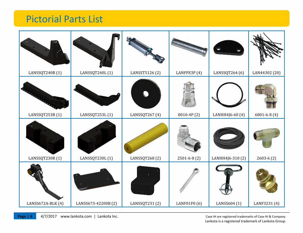
Pictorial Parts List
LANSSQT240R (1) LANSSQT240L (1) LANSST5126 (2) LANFFE3P (4) LANSSQT264 (6) LAN44302 (20)
LANSSQT253R (1) LANSSQT253L (1) LANSSQT267 (4) 8010-4P (2) LANHH4J6-60 (4) 6801-6-8 (4)
LANSSQT230R (1) LANSSQT230L (1) LANSSQT268 (2) 2501-6-8 (2) LANHH4J6-310 (2) 2603-6 (2)
LANSS672A-BLK (4) LANSS673-42200B (2) LANSSQT231 (2) LANF01F0 (6) LANSS604 (1) LANF3231 (4)

4/7/2017 www.lankota.com | Lankota Inc. Case IH are registered trademarks of Case IH & Company. Lankota is a registered trademark of Lankota Group.
Page | 5
Pictorial Parts List
LANFB810 (6) LANFB808 (6) LANFWS58 (6) REDWU58 (18) LANFXFY9 (12)
REDB306 (6) LAN18000 (6) LAN3718 (6) RED706K (20) RED706 (4)
REDB712 (4) LAN690830 (24)

4/7/2017 www.lankota.com | Lankota Inc. Case IH are registered trademarks of Case IH & Company. Lankota is a registered trademark of Lankota Group.
Page | 6
Figure 1
Preparation
1. Park Tractor on level ground and put in park.
2. Turn off the tractors and remove key.
3. Open the hood.
Installation
Refer to Figures 1 & 2 1. Remove the tool boxes from the 3/4” Bracket. 2. Remove the toolbox brackets from the frame.
Refer to Figure 3 3. Remove the (4) M20 bolts holding the front bumper plate on.
Figure 2 Figure 3

4/7/2017 www.lankota.com | Lankota Inc. Case IH are registered trademarks of Case IH & Company. Lankota is a registered trademark of Lankota Group.
Page | 7
Installation
Refer to Figures 4 & 5
4. Set the LANSSQT230L & R brackets on the LANSSQT240L & R brackets respectively. Use the 3/4 x 2” bolts (LANFB808), SAE Washers (LANFWS58), Flat Washers (REDWU58) and the center lock nuts (LANFXFY9) to connect them. Do no tighten yet.
5. Lift the combined brackets into place and bolt to the frame with the 3/4 x 2.5” bolts (LANFB810), Flat Washers (REDWU58) and the center lock nuts (LANFXFY9). Do not tighten yet.
Figure 4 Figure 5

4/7/2017 www.lankota.com | Lankota Inc. Case IH are registered trademarks of Case IH & Company. Lankota is a registered trademark of Lankota Group.
Page | 8
Installation
Refer to Figures 6-8
6. Install the 2.5” Pin (LANSSQT268) in each side. Use 5/8” x 1.5” bolts and the pin caps to keep the pins in place.
7. Install weldments LANSSQT253L & R onto their respective side. Cap the ends of the pins with the remaining bolts and pin caps.
8. Install the grease zerks into the 240 and 253 weld-ments to lubricate the pin.
Figure 6
Figure 7
Figure 8

4/7/2017 www.lankota.com | Lankota Inc. Case IH are registered trademarks of Case IH & Company. Lankota is a registered trademark of Lankota Group.
Page | 9
Figure 10
Installation
Refer to Figures 9 & 10
9. Install the hydraulic cylinders with the rod end pointing down. Attach it with the 1” x 4” clevis pins (LANFFE3P) and retain them with the cotter pins (LANF01F0).
Note: Make sure that the hydraulic ports are facing up when installed. It may be necessary to unfasten the tie rods and rotate a cast piece 90 deg.
10. Visually square the arm with the track and tighten 3/4” bolts on the frame completely.
11. Level the arm by adjusting the clevis on the cylinder.
Figure 9

4/7/2017 www.lankota.com | Lankota Inc. Case IH are registered trademarks of Case IH & Company. Lankota is a registered trademark of Lankota Group.
Page | 10
Figure 11
Installation
Refer to Figure 11 12. Install Shoes (LANSS671-42BLK) onto arms.
Hardware Used: LAN690830 5/8” Serrated Flange Nuts RED706K 5/8” x 1.5” Carriage Bolts
Note: Install arm assemblies (LANSS672A-BLK) first, then mount the shoes (LANSS673-42200-BLK).
Figure 12

4/7/2017 www.lankota.com | Lankota Inc. Case IH are registered trademarks of Case IH & Company. Lankota is a registered trademark of Lankota Group.
Page | 11
Figure 13
Installation
Refer to Figure 13
13. Install (2) LANHH4J6-60 Hoses to each cylinder and route around and behind the radiator.
Hardware:
6801-6-8 ORB 8M x JIC 6M Elbow
14. If the tractor has a tow cable, it can be stored on the pipe of LANSSQT253L and secured with the provided Hitch Pin (LANSS604).

4/7/2017 www.lankota.com | Lankota Inc. Case IH are registered trademarks of Case IH & Company. Lankota is a registered trademark of Lankota Group.
Page | 12
Installation
Refer to Figures 14-19 15. Install LANHH4J6-310 Hydraulic hose from rear remotes of tractor to front. Connect to 60” hydraulic hoses using Tee’s.
Hardware: 2603-6 JIC 6M Tee 2501-6-8 JIG 6M x 1/2” NPT Elbow 8010-4P Pioneer Quick Coupler
Note: The use of stiff wire may assist you in routing wire through rear housing of tractor. Zip Tie where needed. Figures 14-19
4/7/2017 www.lankota.com | Lankota Inc. Case IH are registered trademarks of Case IH & Company. Lankota is a registered trademark of Lankota Group.
Page | 13
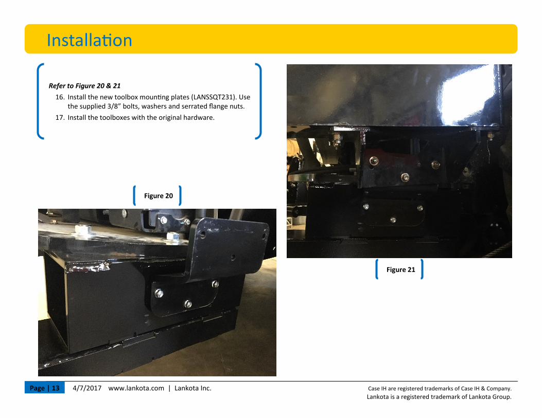
Figure 20
Installation
Refer to Figure 20 & 21
16. Install the new toolbox mounting plates (LANSSQT231). Use the supplied 3/8” bolts, washers and serrated flange nuts.
17. Install the toolboxes with the original hardware.
Figure 21

4/7/2017 www.lankota.com | Lankota Inc. Case IH are registered trademarks of Case IH & Company. Lankota is a registered trademark of Lankota Group.
Page | 14
Installation
Refer to Figure 22
18. Adjust shoes to 1” above the ground by adjusting chain on shoe. Use block under shoe to loosen chain for adjustment.
Refer to Figure 23
19. Lift Shoe with hydraulics and adjust the stop (LANSSQT264) so shoe will not hit tool boxes.
Note: If all hydraulic remotes are used, the Stalk Stompers can be Tee’d together with implement raise/lower functions. Recommend replac-ing elbow with Tee at end of 310” hoses. Install female pioneer couplers in open port on Tee to allow easy implement hooking/unhooking. This hardware is not supplied.
Figure 22 Figure 23

4/7/2017 www.lankota.com | Lankota Inc. Case IH are registered trademarks of Case IH & Company. Lankota is a registered trademark of Lankota Group.
Page | 15
Stalk Stomper Disclaimer
Stalk Stomper Disclaimer The most effective use of the Lankota Stalk Stomper® is achieved by adjusting the stomper pad so that when the corn head is at its normal cutting height, the pad of the shoe is 1” above the ground. Over compression of the spring can shorten the life of the stomper spring, increase wear on the poly liner, and may result in undue damage NOT covered by Lankota’s Limited Warranty.
For further technical assistance,
call Lankota Inc. at:
1-866-526-5682