Embed Size (px)
Citation preview

LANDING SYSTEMS
BY, GIRIDHARAN.R (110051101041) GIRIDHARAN.V (110051101042)
GOWTHAM.P (110051101043) HARIHARA SUBRAMANIAN.G (110051101045)

GIRIDHARAN.V - GIRIDHARAN.R - GOWTHAM.P - HARIHARASUBRAMANIAN.G
INSTRUMENT LANDING SYSTEM( ILS )

GIRIDHARAN.V - GIRIDHARAN.R - GOWTHAM.P - HARIHARASUBRAMANIAN.G
ILS
• An instrument landing system (ILS) is a ground-based instrument approach system that provides precision lateral and vertical guidance to an aircraft approaching and landing on a runway, using a combination of radio signals and, in many cases, high-intensity lighting arrays to enable a safe landing during instrument meteorological conditions (IMC), such as low ceilings or reduced visibility due to fog, rain, or blowing snow.

GIRIDHARAN.V - GIRIDHARAN.R - GOWTHAM.P - HARIHARASUBRAMANIAN.G
ILS

GIRIDHARAN.V - GIRIDHARAN.R - GOWTHAM.P - HARIHARASUBRAMANIAN.G
ILS COMPONENTS

GIRIDHARAN.V - GIRIDHARAN.R - GOWTHAM.P - HARIHARASUBRAMANIAN.G
ILS - PLACEMENT OF PARTS

GIRIDHARAN.V - GIRIDHARAN.R - GOWTHAM.P - HARIHARASUBRAMANIAN.G
LOCALIZER● Aids the pilot in lining up his/her aircraft in the proper azimuth approach to the runway.● Consists of a group of transmitters and antennas positioned at the far end of the runway.● The antenna radiation pattern has a 5 DEGREE beawidth, centred along the runway.● The VHF frequencies used for the localise are in the range 108.1 to 111.9 MHz.● The useful range of the system is about 40 km.

GIRIDHARAN.V - GIRIDHARAN.R - GOWTHAM.P - HARIHARASUBRAMANIAN.G
LOCALIZER
Needle indicates direction of runway.Centered Needle = Correct Alignment

GIRIDHARAN.V - GIRIDHARAN.R - GOWTHAM.P - HARIHARASUBRAMANIAN.G
GLIDE SLOPE● Aids the pilot in making his/her approach at the proper elevation angle to the runway.● Consists of a group of transmitters and antennas positioned beside the runway.● The antenna radiation pattern has a 1o beamwidth, and elevated about 2.5 DEGREES to 2.75 DEGREES in the direction of approach.● The VHF frequencies used for the glide slope are in the range 329.3 to 335.0 MHz.● The useful range of the system is about 40 km.

GIRIDHARAN.V - GIRIDHARAN.R - GOWTHAM.P - HARIHARASUBRAMANIAN.G
GLIDE SCOPE
Needle indicates above/below glidepath.Centered Needle = Correct Glidepath

GIRIDHARAN.V - GIRIDHARAN.R - GOWTHAM.P - HARIHARASUBRAMANIAN.G
MARKER BEACONSFor the purpose of discontinuous addition of navigation data with the value of a momentary distance from the aircraft to the runway’s threshold, the following marker beacons are used:Outer Marker (OM) The outer marker is located 3,5÷6 NM (5.556÷11.112 km) from the runway’s threshold. Its beam intersects the glide slope’s ray at an altitude of approximately 1400 ft (426.72 m) above the runway. It also roughly marks the point at which an aircraft enters the glide slope under normal circumstances, and represents the beginning of the final part of the landing approach. The signal is modulated at a frequency of 400 Hz, made up by a Morse code – a group of two dots per second. On the aircraft, the signal is received by a 75 MHz marker receiver. The pilot hears a tone from the loudspeaker or headphones and a blue indicative bulb lights up. Anywhere an outer marker cannot be placed due to the terrain, a DME unit can be used as a part of the ILS to secure the right fixation on the localizer. In some ILS installations the outer marker is substituted by a Non Directional Beacon (NDB).

GIRIDHARAN.V - GIRIDHARAN.R - GOWTHAM.P - HARIHARASUBRAMANIAN.G
MARKER BEACONSMiddle Marker (MM) The middle marker is used to mark the point of transition from an approach by instruments to a visual one. It’s located about 0,5÷0,8 NM (926÷1482 m) from the runway’s threshold. When flying over it, the aircraft is at an altitude of 200÷250 ft (60,96÷76,2) above it. The audio signal is made up of two dashes or six dots per second. The frequency of the identification tone is 1300 Hz. Passing over the middle marker is visually indicated by a bulb of an amber (yellow) colour . It was removed in some countries, e.g. in Canada.
Inner Marker (IM) The inner marker emits an AM wave with a modulated frequency of 3000 Hz. The identification signal has a pattern of series of dots, in frequency of six dots per second. The beacon is located 60m in front of the runway’s threshold. The inner marker has to be used for systems of the II. and III. category.

GIRIDHARAN.V - GIRIDHARAN.R - GOWTHAM.P - HARIHARASUBRAMANIAN.G
ANALYSISCategories of operation minimums.Category IA minimal height of resolution at 200 ft (60,96 m), whereas the decision height represents an altitude at which the pilot decides upon the visual contact with the runway if he’ll either finish the landing maneuver, or he’ll abort and repeat it.The visibility of the runway is at the minimum 1800 ft (548,64 m)The plane has to be equipped apart from the devices for flying in IFR (Instrument Flight Rules) conditions also with the ILS system and a marker beacon receiver.Category II
A minimal decision height at 100 ft (30,48 m)The visibility of the runway is at the minimum 1200 ft (365,76 m)The plane has to be equipped with a radio altimeter or an inner marker receiver, an autopilot link, a raindrops remover and also a system for the automatic draught control of the engine can be required. The crew consists of two pilots.

GIRIDHARAN.V - GIRIDHARAN.R - GOWTHAM.P - HARIHARASUBRAMANIAN.G
ANALYSIS
Category III AA minimal decision height lower than 100 ft (30,48 m)The visibility of the runway is at the minimum 700 ft (213,36 m)The aircraft has to be equipped with an autopilot with a passive malfunction monitor or a HUD (Head-up display).Category III BA minimal decision height lower than 50 ft (15,24 m)The visibility of the runway is at the minimum 150 ft (45,72 m)A device for alteration of a rolling speed to travel speed.Category III CZero visibility
GIRIDHARAN.V - GIRIDHARAN.R - GOWTHAM.P - HARIHARASUBRAMANIAN.G
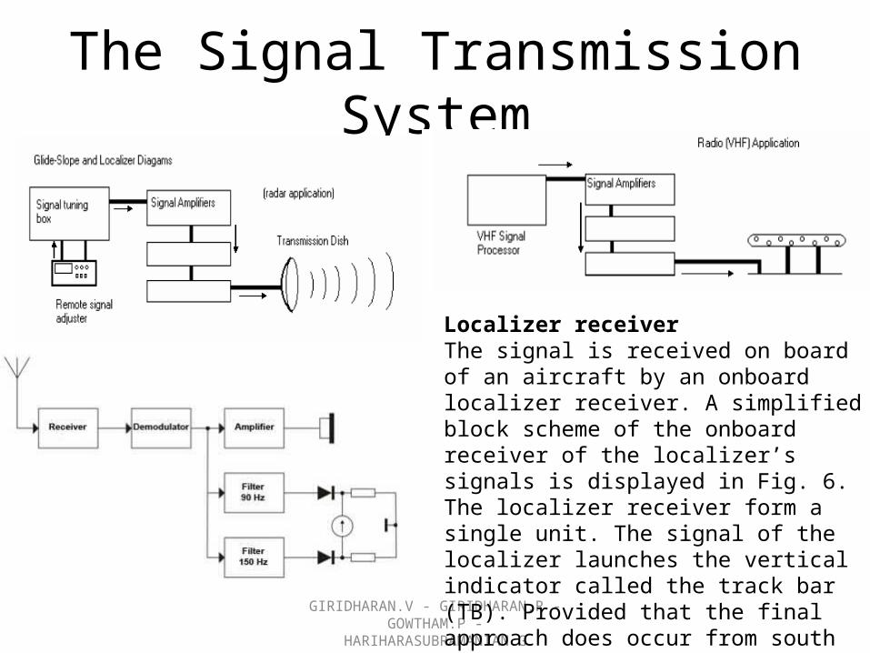
The Signal Transmission System
Localizer receiverThe signal is received on board of an aircraft by an onboard localizer receiver. A simplified block scheme of the onboard receiver of the localizer’s signals is displayed in Fig. 6. The localizer receiver form a single unit. The signal of the localizer launches the vertical indicator called the track bar (TB). Provided that the final approach does occur from south to north, an aircraft flying westward from the runway’s axis

GIRIDHARAN.V - GIRIDHARAN.R - GOWTHAM.P - HARIHARASUBRAMANIAN.G
APPROACH AXIS
A plane flying approximately along the axis of approach, however partially turned away to the left
A plane flying approximately along the axis of approach, however partially turned away to the right

GIRIDHARAN.V - GIRIDHARAN.R - GOWTHAM.P - HARIHARASUBRAMANIAN.G
APPROACH AXISIf the plane’s positioned east from the runway’s axis, the 150 Hz modulated signal causes the track bar to lean out to the right side. In the area of intersection, both signals affect the track bar, which causes to a certain extent a deflection in the direction of the stronger signal. Thus if an aircraft flies roughly in the axis of approach leaned out partially to the right, the track bar is going to deflect a bit to the left. This indicates a necessary correction to the left. In the point where both signals 90 Hz and 150 Hz have the same intensity, the track bar is in the middle. Meaning that the plane is located exactly in the approach axis
A plane flying exactly in the axis of approach

GIRIDHARAN.V - GIRIDHARAN.R - GOWTHAM.P - HARIHARASUBRAMANIAN.G
A plane situated out of reach of the VKV course beacon’s signal
An example of the displayed GS pointer notifying a diversion from the glide slope, a too weak received signal, or an obstacle on the way.

GIRIDHARAN.V - GIRIDHARAN.R - GOWTHAM.P - HARIHARASUBRAMANIAN.G
Both indicators in the middle, which means that the aircraft is located in the point of intersection of the course plane (horizontal) and the glide slope.

GIRIDHARAN.V - GIRIDHARAN.R - GOWTHAM.P - HARIHARASUBRAMANIAN.G
A case when the aircraft is located right of the runway’s axis and too high over the glide slope.
Indicates that the pilot must descent and correct the flight course to the left in order to aquire the correct course and glide slope level.

GIRIDHARAN.V - GIRIDHARAN.R - GOWTHAM.P - HARIHARASUBRAMANIAN.G
A case when the aircraft is located left of the runway’s axis and too low under the glide slope.
A necessity to ascend and adjust the flight course to the right.

GIRIDHARAN.V - GIRIDHARAN.R - GOWTHAM.P - HARIHARASUBRAMANIAN.G
ILS DISADVANTAGES

GIRIDHARAN.V - GIRIDHARAN.R - GOWTHAM.P - HARIHARASUBRAMANIAN.G
MICROWAVE LANDING SYSTEM( MLS )

GIRIDHARAN.V - GIRIDHARAN.R - GOWTHAM.P - HARIHARASUBRAMANIAN.G
INTRODUCTION
● Microwave Landing System (MLS) was designed tohandle the increase in air traffic volume and to satisfythe demand for all-weather landing facilities.● Employs microwave frequencies (5 - 5.25 GHz band)rather than VHF.● MLS provides better accuracy, ease of application,and automation. enables landing down to zero groundvisibility.● ICAO-approved replacement for the ILS system.

GIRIDHARAN.V - GIRIDHARAN.R - GOWTHAM.P - HARIHARASUBRAMANIAN.G
Architecture
● MLS consists of three subsystems: – Localiser, – Glide Slope, and – Flare.● The Localiser and Glide Slope subsystems serve
the same purpose as in ILS.● The Flare provides information on the actual
height of the aircraft above the plane of the runway.

GIRIDHARAN.V - GIRIDHARAN.R - GOWTHAM.P - HARIHARASUBRAMANIAN.G
THE MLS SYSTEMThe Microwave Landing System (MLS) has the following features:
There are 200 channels available worldwide.
The azimuth coverage is at least ± 40° of the runway on-course line (QDM) and glideslopes from .9° to 20° can be selected. The usable range is 20-30 nm from the MLS site; 20nm in the UK.
There is no problem with back-course transmissions; a secondary system is provided to give overshoot and departure guidance ± 20° of runway direction up to 15° in elevation to a range of 10 nm and a height of 10,000 ft.
It operates in the SHF band, 5031 - 5090 MHZ. This enables it to be sited in hilly areas without having to level the site.

GIRIDHARAN.V - GIRIDHARAN.R - GOWTHAM.P - HARIHARASUBRAMANIAN.G
THE MLS SYSTEM (Contd.,) Because of its increased azimuth and elevation coverage aircraft can
choose their own approaches. This will increase runway utilisation and be beneficialto helicopters and STOL aircraft.
The MLS has a built-in DME.
MLS is compatible with conventional localiser and glidepath instruments,
EFIS, auto- pilot systems and area navigation equipment.
The identification prefix for the MLS is an ‘M’ followed by two letters.
The aim is for all MLS equipped aircraft to operate to CAT III criteria.

GIRIDHARAN.V - GIRIDHARAN.R - GOWTHAM.P - HARIHARASUBRAMANIAN.G
MLS FEATURES
GIRIDHARAN.V - GIRIDHARAN.R - GOWTHAM.P - HARIHARASUBRAMANIAN.G
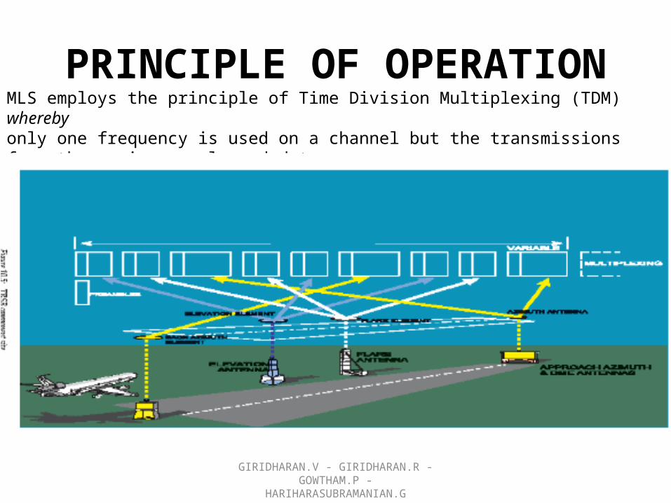
PRINCIPLE OF OPERATIONMLS employs the principle of Time Division Multiplexing (TDM) wherebyonly one frequency is used on a channel but the transmissions from the various angle and dataground equipments are synchronised to assure interference free operations on the commonradio frequency.

GIRIDHARAN.V - GIRIDHARAN.R - GOWTHAM.P - HARIHARASUBRAMANIAN.G
AZIMUTH LOCATION Time referenced scanning beam (TRSB) is utilised in azimuth andelevation as follows: the aircraft computes its azimuth position in relation to the runwaycentre-line by measuring the time interval in microseconds between the receptionthe ‘to’ and ‘fro’ scanning beams.
The beam starts the ‘to’ sweep at one extremity of its total scan and travels at a uniform speed to the other extremity. It then starts its ‘fro’ scan back to its start position. The time interval between the reception of the ‘to’ and ‘fro’ pulses is proportional to theangular position of the aircraft in relation to the runway on-course line.
The pilot can choose to fly the runway on-course line (QDM) or an approach pathwhich he selects as a pre-determined number of degrees ± the runway direction.
GLIDESCOPE LOCATION Another beam scans up and down at a uniform speed within itselevation limits. The aircraft’s position in relation to its selected glideslope angle is thuscalculated in the same manner by measuring the time difference between the reception of the pulses from the up and down sweep. The transmissions from the two beams and the transmissions from the other components of the MLS system are transmitted at different intervals i.e. it uses ‘ time multiplexing’.

GIRIDHARAN.V - GIRIDHARAN.R - GOWTHAM.P - HARIHARASUBRAMANIAN.G
OTHER COMPONENTSOther components of the system are:• Flare. Although the standard has been developed to provide for flareelevation, this function is not intended for future implementation• Back azimuth. Gives overshoot and departure guidance ± 20° of runwaydirection up to 15° in elevation.• DME Range along the MLS course is provided not by markers but by a DME. For Cat II and III approaches a precision DME (DME/P) that is accurate to within 100 feet must be available.• Transmission of auxillary data. This consists of:> station identification> system condition> runway condition> weather information

GIRIDHARAN.V - GIRIDHARAN.R - GOWTHAM.P - HARIHARASUBRAMANIAN.G
Height Calculation
● The angle θ made by the aircraft and the runwayat the point where the flare transmitter is situatedis measured.● The distance d between the flare transmitter andthe runway is known.● The height is calculated using the equation: h = d tan θ

GIRIDHARAN.V - GIRIDHARAN.R - GOWTHAM.P - HARIHARASUBRAMANIAN.G
Aircraft Height Measurement

GIRIDHARAN.V - GIRIDHARAN.R - GOWTHAM.P - HARIHARASUBRAMANIAN.G

GIRIDHARAN.V - GIRIDHARAN.R - GOWTHAM.P - HARIHARASUBRAMANIAN.G

GIRIDHARAN.V - GIRIDHARAN.R - GOWTHAM.P - HARIHARASUBRAMANIAN.G
THANK YOU