Embed Size (px)
Citation preview

Water and Environmental EngineeringDepartment of Chemical EngineeringMaster Thesis 2013
Sha Liu
Landfill leachate treatment methods and evaluation of Hedeskoga
and Måsalycke landfills


Postal address Visiting address Telephone P.O. Box 124 Getingevägen 60 +46 46-222 82 85
SE-221 00 Lund, Sweden +46 46-222 00 00
Web address Telefax
www.vateknik.lth.se +46 46-222 45 26
Landfill leachate treatment methods and
evaluation of Hedeskoga and Måsalycke
landfills
By
Sha Liu
Master Thesis number: 2013-07
Water and Environmental Engineering
Department of Chemical Engineering
Lund University
December 2013
Supervisor: Associate Professor Karin Jönsson
Examiner: Professor Jes la Cour Jansen


Preface
I would like to express my appreciation to all who gave me help and support. It would not
have been possible to write this master thesis without the kind people around me, to only
some of whom it is possible to give particular thanks here.
Foremost, it is with immense gratitude that I acknowledge the support and help from my su-
pervisor, Associate Professor Karin Jönsson for her positive contribution and useful sugges-
tions. Her guidance helped me in all the time of research and writing of this thesis.
Besides my supervisor, I would like to thank my examiner, Professor Jes la Cour Jansen for
his good advice and insightful comments. My sincere thanks also go to Gertrud Persson and
Mahan Amani Geshnigani for their help, advice and encouragement of my experiment.
I owe my deepest gratitude to the management and staff of SYSAV AB especially to Anna
Andersson who introduced information about Måsalycke and Hedeskoga Landfills to me.
Thank you for your patient guidance. Also thanks to Annika Henriksson and Tomas Nilsson
who helped me pick leachate. The next thank goes to VA SYD for providing me the activated
sludge and Jonas Bigelius, Simon Chang and Johan Blomquist for helping me with my Eng-
lish grammar.
Last but not least, I would like to thank my parents, Naibin Liu and Lijuan Sha with their sup-
port and spiritually throughout my life.
Sha Liu
Lund, December 2013


Abstract
Landfill leachate is a liquid that is mainly produced by the rain which falls on the solid waste.
The leachate usually contains high concentrations of ammonium, organic matter, toxic com-
pounds and heavy metals. This master thesis introduces briefly facts of landfills, leachate
formation and leachate characteristics.
The formation of leachate threatens the groundwater, soil and environment. For this reason,
treatment methods to remove ammonium need to be explored. To treat landfill leachate, an
option is to send leachate to a wastewater treatment plant nearby. However, after the sludge
certification system REVAQ has been implemented for increasing the quality of sludge,
leachate in Sweden should be treated on-site instead of being treated in the municipal
wastewater treatment plants. In this thesis, more than twenty leachate treatment methods are
presented including physical/chemical methods and biological methods.
Two landfills will be introduced in this thesis, Hedeskoga and Måsalycke landfills, both lo-
cated in Southern Sweden. Treatment methods and performances will be introduced. The
treated leachate of the two landfills contains comparatively high concentrations of ammonium.
To determine the toxicity of the two landfills, an inhibition test of nitrification was done. Four
kinds of leachate were tested from the two landfills, dilution of 50%, 20%, 10% and 5% of
each leachate was tested with the inhibition ranging from 30% to -19%. Therefore, the rea-
sons for the high ammonium concentration in Hedeskoga landfill may be due to the toxic
problems and cold weather. In order to reduce the high concentration of ammonium, different
leachate treatment methods were evaluated, rotating biological contractor, activated sludge,
trickling filters, biological aerated filters, moving bed biofilm reactors and sequencing batch
reactors are recommended for the two landfills in order to reduce the concentration of ammo-
nium.


Contents
Preface 1
Abstract 3
Contents 5
1 Background 1
1.1 Introduction 1
1.1.1 Solid waste and landfill 1
1.1.2 Landfill leachate 2
1.1.3 Landfill geological scale 3
1.1.4 REVAQ 4
1.2 Objectives 5
2 Composition, standards and management 7
2.1 Leachate composition 7
2.2 Leachate management 8
2.3 Standards to discharge of leachate 9
3 Leachate treatment methods 11
3.1 Historical leachate treatment 11
3.2 Leachate treatment options 11
3.3 Physical/Chemical treatment methods 12
3.3.1 Coagulation-Flocculation 13
3.3.2 Chemical precipitation 13
3.3.3 Flotation 13
3.3.4 Activated carbon adsorption 13
3.3.5 Ammonia stripping 14
3.3.6 Ion exchange 14
3.3.7 Electrochemical treatment 15
3.3.8 Chemical oxidation and AOP advanced oxidation process 15
3.3.9 Membrane filtration 15
3.3.10 Treatment performance of physical/chemical methods 17
3.4 Biological treatment methods 17
3.4.1 Activated sludge 18
3.4.2 Sequencing batch reactors (SBR) 19
3.4.3 Nitrification-denitrification 22
3.4.4 Aerated lagoon 22
3.4.5 Trickling filters 23
3.4.6 Rotating biological contactor 23

3.4.7 Biological aerated filters (BAFs) 24
3.4.8 Moving bed biofilm reactors (MBBR) 25
3.4.9 Upflow anaerobic sludge blanket (UASB) 26
3.4.10 Anaerobic filter 26
3.4.11 Constructed wetland and reed beds 27
3.4.12 Leachate recirculation 28
3.4.13 Treatment performance of biological methods 28
4 Description of Hedeskoga and Måsalycke 29
4.1 Introduction 29
4.1.1 Hedeskoga 29
4.1.2 Måsalycke 30
4.2 Leachate treatment 30
4.2.1 Hedeskoga 30
4.2.2 Måsalycke 31
4.3 Situation of today 32
4.3.1 Hedeskoga 32
4.3.2 Måsalycke 33
5 Inhibition of nitrification 35
5.1 Methodology 35
5.1.1 Relevant parameters, chemical symbols and formulas 35
5.2 Experiment 36
5.2.1 SS of activated sludge 36
5.2.2 Activated sludge suspension 37
5.3 Results and analyses 37
6 Discussion 41
6.1 Limitations 41
6.2 Proposed reasons for limited nitrification 41
6.2.1 Pond capacity 41
6.2.2 Toxic problem 42
6.2.3 Environmental problem 42
6.3 Recommendations 43
7 Conclusions 45
8 References 47
9 Appendix 53

1
1 Background
Water tension has become a significant problem all over the world. According to numbers
given by WHO (2012), 1.1 billion people of the world do not have improved water and 2.4
billion people do not have any type of improved sanitation facilities. Approximately 3.4 mil-
lion people die every year because of water-related diseases which corresponds to almost the
whole city of Los Angeles (Prüss-Üstün et al., 2008).
The world water situation is shown in Picture 1, the “high stress” and “very high stress” cate-
gories are labeled as “severe stress” category when referred to jointly. The withdrawal-to-
availability ratio (CR) over 0.4 indicates that the risk of absolute water shortages during low
flow periods will be especially high (Alcamo et al., 2000).
Figure 1 The world today (1995): water stress (Alcamo et al., 2000), reprinted with permis-
sion.
The main sources for supplying water are groundwater and surface water. The quality of
groundwater is depending on the aquifer, human activities and also the utilization of dumping
sites. Groundwater has a high risk of being polluted around areas near landfills because of the
potential pollution source of landfill leachate. Hence, the study of landfill leachate has be-
come a special issue in recent years.
1.1 Introduction
1.1.1 Solid waste and landfill
Solid waste can be classified into three types depending on different sources: municipal waste,
industrial waste and biomedical waste. The most common solid waste is municipal solid
waste which is known as garbage that mainly comes from residential and commercial com-
plexes, for example newspapers, furniture, clothing, food, batteries and all kinds of matters.
In Sweden, 96% of the solid waste is incinerated into renewable energy and only 4% of the
total solid waste reaches landfills (Björklund, 2003). Sometimes, the waste made by the citi-

2
zens is not enough to be burned and Sweden needs to import 800,000 tons of waste per year
to incinerate for energy (Clark, 2012). Figure 2 is the generation of municipal solid waste in
Sweden in eleven years from 2001 to 2011. The number increased over the years from 2001
to 2007 with the exception of 2004. The number decreased to 460 kg per capita in 2011.
Figure 2 Municipal waste generation in Sweden, kg per capita (Eurostat, 2012).
The possible reason of the dropping in 2009, 2010 and 2011 may be because of the economic
recession, as reduced consumption inevitably led to reduction of waste or maybe due to the
increased environmental awareness (Milios, 2013).
Nowadays, in many countries, disposal of solid waste to landfills is a general way for waste
discharge. A landfill is a site for the disposal of waste materials. It is the oldest and most
common form of waste treatment and it can also be used as a temporary storage, consolidation
and transfer place (SOLMAX, 2012). The types of landfills can be classified from different
perspectives, e.g. prescriptive, performance and effects/risk based. However, in practice, the
classification is not only limited to one perspective, a combination of requirements and crite-
ria can be used during practical utilization (URS, 2001).
One way to classify landfills is to describe them as single liner systems, composite liner sys-
tems and double liner systems. Landfill liners are designed to generate a barrier between the
waste and the environment and to drain the leachate for collection and transfer to treatment
facilities. Integrated into all liner systems is a leachate collection system which is composed
of sand and gravel or a geonet - a plastic net like a drainage blanket (Heimlich et al., n.d.).
Landfills can also be classified as sanitary landfills, municipal solid waste (MSW) landfills,
construction and demolition waste landfills or industrial waste landfills (Wroblewski et al.,
n.d.).
1.1.2 Landfill leachate
Landfill leachate is a liquid that is mainly produced by the rain which falls on the top of the
landfill. The rainwater infiltrates into the garbage and generates physical mixing and chemical
reactions with the components existing in the waste. The leachate usually contains high con-
centrations of ammonium, organic matter, toxic compounds and heavy metals. The risk of
0
100
200
300
400
500
600
2001 2002 2003 2004 2005 2006 2007 2008 2009 2010 2011
kg per capita
Year

3
leachate leakage to the groundwater is mainly because of inappropriate geological material
under the landfill. Also, toxic materials and heavy metals in leachate may cause prolonged
harmful health problems for humans.
According to the landfill age, leachate can be classified into three types: young leachate, in-
termediate leachate and stabilized leachate. Sometimes, young leachate and intermediate
leachate are merged as one category: young leachate below 5 years. The characteristics of
leachate in this period contain high concentration of biodegradable organic compounds such
as volatile fatty acids (VFAs), high BOD (4,000 – 13,000 mg/L), high concentration of COD
(6,000 – 60,000 mg/L), high concentration of NH4+-N (2,000 – 5,000 mg/L) and a high ratio
of BOD/COD ranging from 0.4 – 0.7 (Kurniawan, 2011).
As the age of a landfill increases, the microorganisms degrade the compounds by breaking
down the organic materials into methane and CO2. Reducing CO2 with hydrogen, the pH in-
creases to over 7.0 and the leachate organic compounds are not biodegradable any more. The
leachate then turns to stabilized leachate (Mårtensson et al, 1999). This phase may take over
50 years or more (Gurijala and Suflita, 1993). The stabilized leachate contains high concentra-
tion of NH4+-N (2,500 – 5,000 mg/L), high concentration of COD (5,000 – 20,000 mg/L) and
low BOD/COD ratio less than 0.1 (Kurniawan, 2011). Table 1 is the classification of landfill
leachate by landfill age.
Table 1 Landfill leachate classification (Alvarez-Vazquez et al., 2004).
Type of leachate Young Intermediate Stabilized
Age of landfill (years)
pH
BOD/COD
COD (g/L)
NH4+-N (mg/L)
TOC/COD
Kjeldahl nitrogen (g/L)
Heavy metals (mg/L)
<1
<6.5
>0.5
>15
<400
<0.3
0.1-2
>2
1-5
6.5-7.5
0.1-0.5
3-15
NA
0.3-0.5
NA
<2
>5
>7.5
<0.1
<3
>400
>0.5
NA
<2
Leachate also can be classified according to the state of degradation of the waste materials as
acidogenic phase and methanogenic phase. Methanogenic leachate is generated from old land-
fills where extensive degradation of organic matters in the waste occurs. The final products of
reaction are methane and carbon dioxide (Carville, 2013).
1.1.3 Landfill geological scale
Landfills can be established on the ground or on artificial islands in the sea, but it is rare to
see landfills in the sea because of the complex geological scale and high cost, unless in some
coastal countries where there are lack of land sources, for example, Japan and Singapore (楼
紫阳 et al., 2006). Therefore, the most ordinary landfills now are built on the ground. The
ground landfills use natural geological formations and liners for keeping and treating waste.
Landfills should be located in an impermeable geological area which can stop percolation of
leachate into groundwater. There are four critical elements in a secure landfill: a bottom liner,
a cover, a leachate collection system and the natural hydrogeological setting. The natural set-

4
ting is selected to minimize the possibility of leachate infiltrating to groundwater, and the oth-
er three elements are engineered.
A natural hydrogeological setting should satisfy two things: the rock formation should be as
impermeable as possible in order to prevent the leakage of leachate; if the leakage occurs, it is
possible to drill wells into the ground and simply pump polluted water out. The bottom liner
should consist of several sloped layers of clay or a synthetic flexible membrane (or combina-
tion of these). There are three types of liner materials: clay, plastic and composite. A cover is
a protection part on top of landfills. Generally, a cover consists of several layers: clay or
membrane liner. The purpose is to keep water out from waste in order to prevent leachate
formation (Montague, 1982). The leachate collection and sealing system seeps to the bottom
of a landfill and collect leachate by pipes. The system has two main aspects: one is artificial
sealing liner, and one is drainage layer ≥ 0.5m thickness (SEPA, 2002). Figure 3 shows the
cross section of a landfill.
Figure 3 Cross section of a landfill (SEPA, 2002).
1.1.4 REVAQ
REVAQ started in 2002 as a development project. It is a regulation that is set to increase
sludge quality and to develop a sustainable strategy for reducing pollution risk to the envi-
ronment (Svensktvatten, 2013). REVAQ gives a forced rule to be followed for further im-
provement of the sludge quality.
Since the law on the usage of sludge in agriculture is not sufficient, regulations should be
made on sustainable phosphorus recycling to agriculture land. REVAQ has been discussed
extensively during past years. Lately, the regulation has been introduced at many waste water
treatment plants in Sweden. To get a good quality of sludge, it is necessary to have a better
quality of influent into treatment plants.
In Sweden, leachate used to be discharged to waste water treatment plants. After the REVAQ
statement came into force, Hedeskoga and Måsalycke, the two landfills will be discussed in
this thesis, leachate is not allowed to be led to waste water treatment plants anymore. The two
5
landfills initially have ponds which were used as reservoirs. After the REVAQ regulation was
declared, researches started to find a suitable method for on-site treatment of leachate. But the
result was not as good as expected and the old ponds could not take effects as a treatment
plant. Therefore, this thesis was proposed in order to have a literature study of landfill leach-
ate treatment methods and to give some ideas about problems that exist in these two sites.
1.2 Objectives
The objectives of this thesis are:
- To describe different types of leachate from municipal landfills based on literature.
- To present relevant treatment methods for different types of leachate.
- To evaluate inhibition of nitrification of leachates from two landfills in southern Sweden
where discharge requirements for discharge is not fulfilled.
- To suggest potential treatment methods for the leachates from the two sites, needed to fulfill
on-site treatment demands.

6
7
2 Composition, standards and management
2.1 Leachate composition
Leachate is a complex material which contains e.g. water, organic materials, inorganic mate-
rials, bacteria and other microorganisms. Leachate varies from site to site, and its characteris-
tics may change over time due to the degradation in the landfills.
When the landfills receive materials from industries, households and municipal activities, the
leachate have different composition and characteristics which means they have to be treated in
multiple ways. The composition of solid waste in landfill is dominated by biodegradable
waste with naturally present bacteria. The decomposition of the solid waste occurs in four
phases: an initial aerobic phase; an anaerobic acid phase; an initial methanogenic phase and a
stable methanogenic phase (Kjeldsen et al., 2002). Table 2 shows the composition of landfill
leachate with concentration ranges.
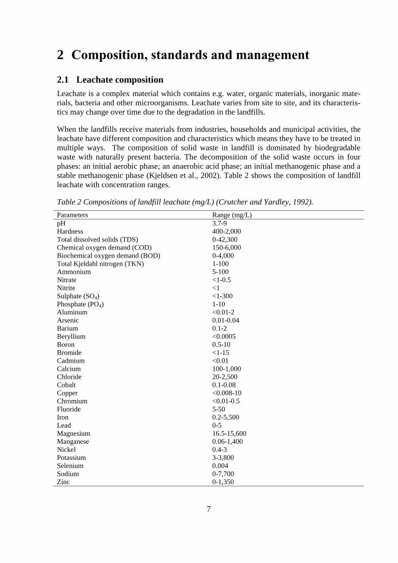
Table 2 Compositions of landfill leachate (mg/L) (Crutcher and Yardley, 1992).
Parameters Range (mg/L)
pH
Hardness
Total dissolved solids (TDS)
Chemical oxygen demand (COD)
Biochemical oxygen demand (BOD)
Total Kjeldahl nitrogen (TKN)
Ammonium
Nitrate
Nitrite
Sulphate (SO4)
Phosphate (PO4)
Aluminum
Arsenic
Barium
Beryllium
Boron
Bromide
Cadmium
Calcium
Chloride
Cobalt
Copper
Chromium
Fluoride
Iron
Lead
Magnesium
Manganese
Nickel
Potassium
Selenium
Sodium
Zinc
3.7-9
400-2,000
0-42,300
150-6,000
0-4,000
1-100
5-100
<1-0.5
<1
<1-300
1-10
<0.01-2
0.01-0.04
0.1-2
<0.0005
0.5-10
<1-15
<0.01
100-1,000
20-2,500
0.1-0.08
<0.008-10
<0.01-0.5
5-50
0.2-5,500
0-5
16.5-15,600
0.06-1,400
0.4-3
3-3,800
0.004
0-7,700
0-1,350
8
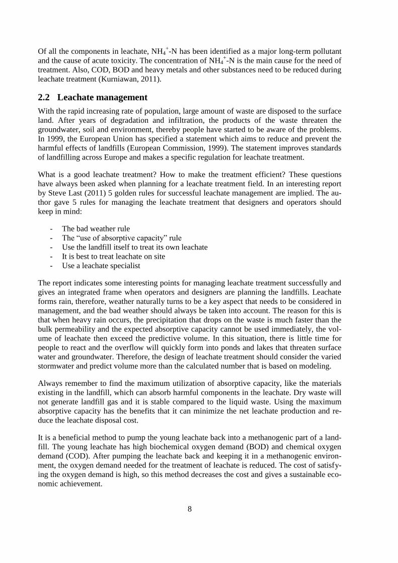
Of all the components in leachate, NH4+-N has been identified as a major long-term pollutant
and the cause of acute toxicity. The concentration of NH4+-N is the main cause for the need of
treatment. Also, COD, BOD and heavy metals and other substances need to be reduced during
leachate treatment (Kurniawan, 2011).
2.2 Leachate management
With the rapid increasing rate of population, large amount of waste are disposed to the surface
land. After years of degradation and infiltration, the products of the waste threaten the
groundwater, soil and environment, thereby people have started to be aware of the problems.
In 1999, the European Union has specified a statement which aims to reduce and prevent the
harmful effects of landfills (European Commission, 1999). The statement improves standards
of landfilling across Europe and makes a specific regulation for leachate treatment.
What is a good leachate treatment? How to make the treatment efficient? These questions
have always been asked when planning for a leachate treatment field. In an interesting report
by Steve Last (2011) 5 golden rules for successful leachate management are implied. The au-
thor gave 5 rules for managing the leachate treatment that designers and operators should
keep in mind:
- The bad weather rule
- The “use of absorptive capacity” rule
- Use the landfill itself to treat its own leachate
- It is best to treat leachate on site
- Use a leachate specialist
The report indicates some interesting points for managing leachate treatment successfully and
gives an integrated frame when operators and designers are planning the landfills. Leachate
forms rain, therefore, weather naturally turns to be a key aspect that needs to be considered in
management, and the bad weather should always be taken into account. The reason for this is
that when heavy rain occurs, the precipitation that drops on the waste is much faster than the
bulk permeability and the expected absorptive capacity cannot be used immediately, the vol-
ume of leachate then exceed the predictive volume. In this situation, there is little time for
people to react and the overflow will quickly form into ponds and lakes that threaten surface
water and groundwater. Therefore, the design of leachate treatment should consider the varied
stormwater and predict volume more than the calculated number that is based on modeling.
Always remember to find the maximum utilization of absorptive capacity, like the materials
existing in the landfill, which can absorb harmful components in the leachate. Dry waste will
not generate landfill gas and it is stable compared to the liquid waste. Using the maximum
absorptive capacity has the benefits that it can minimize the net leachate production and re-
duce the leachate disposal cost.
It is a beneficial method to pump the young leachate back into a methanogenic part of a land-
fill. The young leachate has high biochemical oxygen demand (BOD) and chemical oxygen
demand (COD). After pumping the leachate back and keeping it in a methanogenic environ-
ment, the oxygen demand needed for the treatment of leachate is reduced. The cost of satisfy-
ing the oxygen demand is high, so this method decreases the cost and gives a sustainable eco-
nomic achievement.

9
On-site leachate treatment is the most common and economical method to treat leachate now.
Many countries’ authorities suggest that leachate should be discharged to the waste water
treatment plant (WWTP) nearby. Actually, it is not a good regulation because leachate con-
tains much higher concentration of ammonia nitrogen than domestic and industrial sewage.
Another drawback of sending leachate to WWTP is the methane gas from leachate. The gas
will release from leachate during transfer. However, in fairness, leachate will produce me-
thane gas and release to atmosphere wherever it is.
Last but not least, always take the advices of a leachate specialist. The experts will provide
the best methods for treating leachate which are economic, environmental and sustainable.
2.3 Standards to discharge of leachate
The discharge standards of landfill leachate should be considered in several aspects: the con-
tinuous impact to the environment, the leachate quality, economic abilities and the practical
situation of the landfill. Standards intend to provide executive criteria to be followed. The
standard varies in different countries. Table 3 gives an example of limiting concentration to
discharge of landfill leachate in Germany.
Table 3 Limiting concentration to discharge of landfill leachate in Germany (ANONYMUS,
1996).
Parameters Limiting concentration (mg/L)
COD
BOD5
Nitrogen, total
Phosphorus, total
Hydrocarbons
Nitrite – Nitrogen
AOX
Mercury
Cadmium
Chromium
Chromium (VI)
Nickel
Lead
Copper
Zinc
Cyanide, easy releasable
Sulfide
200
20
70
3
10
2
0.5
0.05
0.1
0.5
0.1
1
0.5
0.5
2
0.2
1

10

11
3 Leachate treatment methods
Leachate treatment is done either biological or physical/chemical. Because of the multiple
characteristics of leachate, one single method could not be sufficient to produce the ideal re-
sult. To have a better treatment performance, an integrated system is used which combines the
two methods.
This thesis is mainly focus on introduce some biological treatment methods of landfill leach-
ate and physical/chemical treatment methods will only be introduced briefly.
3.1 Historical leachate treatment
In late 1960s, the UK government set the regulation that the landfill sites should have a per-
meable underlying geological material in order to prevent the build-up of leachate. This regu-
lation had been found to cause many environmental problems after several years. Then many
European countries decided to locate landfills in a groundwater free clay geological condi-
tions or to seal each site with an engineered lining that could prevent infiltration of leachate.
After that, United States began using multiple lining layers in landfills, this method soon be-
came a principle for the world.
Nowadays, many leachate treatment methods have been used in the world, physical, chemical,
biological and combined processes. Coagulation, precipitation, adsorption, membrane pro-
cesses and some new methods have been added into the leachate treatment procedures in or-
der to remove organic compounds, ammoniacal nitrogen, heavy mental, entrained oil and col-
loidal material.
3.2 Leachate treatment options
For years, many leachate treatment methods have been investigated. Thereby, discussions put
in light of which methods are the most suitable for the landfill leachate. For the purposes of
removing different chemical compounds, e.g. COD, BOD, NH4+-N, heavy metals, the differ-
ent characteristics of the leachate, the advantages and drawbacks of various treatments should
be considered carefully. Thus, new technologies and conventional methods should be devel-
oped in order to be environmentally and financially attractive. Table 4 enumerates treatment
options depending on different removal purposes.
The choice of leachate treatment may be tied to regulations at national and regional level. So
the choice may change because of the flexible regulations in different countries. Options
should follow the regional considerations, environmental aspects and serious evaluation alter-
natives. Some countries may have very specific standards which leaves little flexibility in the
choice of leachate management (Johannessen, n.d.).

12
Table 4 Treatment options (Johannessen, n.d.).
Treatment objectives Main treatment options
Removal of degradable organic (BOD) Aerobic biological:
Aerated lagoon/extended aeration
Activated sludge
Sequencing batch reactor (SBR)
Anaerobic biological:
Upflow sludge blanket
Removal of ammonium Aerobic nitrification:
Activated sludge
Aerated lagoon/extended aeration
Rotating biological contractor
Sequencing batch reactor
Vegetated ditch (artificial wetlands)
Ammonia stripping
Denitrification Anoxic biological
Sequencing batch reactor
Vegetated ditch (artificial wetlands)
Removal of non-degradable organic and color Lime / coagulant addition
Activated lagoon
Reverse osmosis
Chemical oxidation
Removal of hazardous trace organic Activated carbon
Reverse osmosis
Chemical oxidation
Odor removal Hydrogen peroxide
Removal of dissolved iron and heavy metals
and suspended solids
Lime / coagulant addition, aeration and setting
Final polishing Artificial wetlands (e.g. reed beds, ponds)
Disinfection Hypochlorite
Volume reduction / pre-concentration Reverse osmosis
evaporation
3.3 Physical/Chemical treatment methods
For stabilized landfill leachate that contains high concentration of bio-toxicity and lack of
degradable organic matters are hard to degrade. In this situation, an alternative and low cost
efficient method should be introduced to the leachate treatment. The methods are used along-
side biological processes in order to achieve the standards. Physical/chemical treatment meth-
od is a non-biological method used in leachate treatment as a pre-treatment and a post-
treatment method.
It is necessary to establish on-site facilities when discharge leachate to wastewater treatment
plant is not feasible. The treatment facilities are located beside the dump site and leachate is
pumped into a treatment pond nearby. Leachate mixes with chemical compounds and settles
with the solid contaminants in the tank before it goes to the second process.
Below, some physical-chemical methods will be introduced, e.g. on-site leachate treatment,
coagulation-flocculation, chemical precipitation, flotation, activated carbon adsorption, am-
13
monium stripping, ion exchange, membrane filtration, electronic chemical treatment and
chemical oxidation, advanced oxidation process (AOP).
3.3.1 Coagulation-Flocculation
Coagulation-Flocculation is a process of removing non-biodegradable organic compounds
and heavy metals from leachate by adding coagulants (Diamadopoulos, 1994). Most of the
colloidal particles have negative charge. To maximize the neutralization, the coagulants re-
duce the electric repulsion effects between particles in order to unite for precipitation. The
coagulants can be aluminum sulphate, ferrous sulphate, ferric chloride or ferric chloro-
sulphate.
From the results of some experiments, the COD removal of this method range between 30%
and 86%, and heavy metal removal range between 74% and 98% (Kurniawan, 2011).
3.3.2 Chemical precipitation
Chemical precipitation is to precipitate the non-biodegradable organic compounds and heavy
metals by the addition of precipitation reagents, then filtration can be used to remove the par-
ticles from the mixture. This method is primarily for the removal of heavy metals, non-
biodegradable organic compounds and NH4+-N. It can also to be used to remove phosphorus,
fluoride, ferro-cyanide and other inorganics. The removal efficiency is mainly depending on
the metal present, the concentration of the metal and the reagents.
The ammonium removal efficiency by chemical precipitation is generally between 90% and
98% with an initial concentration in leachate range from 1,380 mg/L to 5,618 mg/L (Kur-
niawan, 2011).
3.3.3 Flotation
Flotation is a separation process which utilizes gas bubbles to attach to solid particles in sus-
pension in order to make them float on the surface of the liquid. The main application of flota-
tion process is wastewater treatment and focus on the removal of solids, ions, macromolecules
and fibers in the waste. The efficient removal result, high throughput and low sludge genera-
tion (compares to activated sludge method) now attract people to use this method on leachate
treatment (Rubio et al., 2002).
The flotation method has been in investigation for removal humic acid in leachate treatment
as a post-treatment after biological treatment, and the result of the treatment was proven effi-
cient with the removal performance up to 99% (Zouboulis et al., 2003). It seems that the flota-
tion method will become an alternative technology for the humic acid removal.
3.3.4 Activated carbon adsorption
Adsorption is a method where dissolved compounds are adsorbed to the surface of an adsorb-
ing medium which have a very big internal surface. This process happens when the attractive
forces of the carbon surface overcome the attractive forces of the liquid (CARBTROL, 1992).
The adsorbing mediums could use powdered activated carbon (PAC) or granular activated
carbon (GAC). These two adsorptive materials may be used to achieve a low adsorption affin-
ity for low molecular weight and polar organic species. GAC is the most popular adsorbent
solid used in wastewater treatment due to its high surface area to volume ratio. The advantage
of GAC is that the adsorption of target compounds and filtration of suspended solids can be

14
finished by one step and reduce the chance of accumulation particles drop to the bottom
where particles would be hard to remove.
Until now, lots of experiments have been made with activated carbon in leachate treatment. In
general, the activated carbon adsorption method is found to be an efficient method to remove
non-biodegradable compounds and heavy metals, but not for NH4+-N.
The removal result of heavy metals is 80% to 96% with an initial concentration of 184 mg/L,
and more than 90% of COD can be removed with its concentration ranging from 940 mg/L to
7,000 mg/L (Kurniawan, 2011).
3.3.5 Ammonia stripping
Ammonia stripping is a process which aims to reduce the concentration of ammonium in
wastewater. In this method, pH plays an important role. When the pH is 7 or below, all the
ammonia will turn to soluble ammonium. When pH is reaching 11, only dissolved ammonia
gas is present which could be released from wastewater. Therefore, in the stripper, pH should
be adjusted to 11-12 by adding NaOH.
The equilibrium reaction for ammonia stripping is:
NH4+ + OH
- →NH3 ↑ + H2O (1)
On the whole, the NH4+-N removal performance of ammonia stripping is about 85% to 95%
with its initial concentration ranging from 220 mg/L to 2,215 mg/L. If the ammonium content
is higher, it is more economical to use alternate ammonium removal techniques, e.g. steam
stripping or biological methods. As can be seen in equilibrium reaction (1), the final product
is NH3 gas. There are three possible methods for the disposal of ammonia gas: air disposal;
concentration as ammonium sulfate and thermal destruction (Kurniawan, 2011).
This method has no backwash or regeneration and it is unaffected by toxic compounds. Even
though, there are still some disadvantages to the process. The requirement of high pH may
create maintenance concerns and the efficiency of removal result is limited by temperature.
Also, this method does not remove nitrite and nitrogen. Most importantly, release of ammonia
gas may affect the environment (EPA, 2000).
3.3.6 Ion exchange
Ion exchange is a process that swaps ions between solid and liquid status where there is no
permanent change in the structure of the solid. The equilibrium reaction can be displayed as:
nRSO3- - H
+ + M
n+ ↔ nRSO3
- - M
n+ + nH
+ (2)
Resin Solution Resin Solution
Where (-nRSO3-) and M represent the anionic group attached to the ion exchange resin and
the metal cation respectively. Where n is the coefficient of the reaction component, depending
on the oxidation state of the metal ions (Dabrowski et al., 2004).
Ion exchange can be operated in two modes: batch mode and continuous mode. In batch
modes, resins are stirred with contaminated water in a reactor and removed by settling. In
continuous modes, the exchange material is placed in a bed and water passes through it and
the resins are removed at the bottom (Tchobanoglous et al., 2002).

15
Nowadays, researchers would like to use this method for the removal of heavy metals. An
experiment shows that the ion exchange method had a heavy metal removal performance was
between 90% and 99% (Majone et al., 1998). However, because of the high operation cost
and a pre-treated system for removal of suspended solid is needed, the method is limited for
economic reason (Kurniawan, 2011).
3.3.7 Electrochemical treatment
The electrochemical treatment is mainly used in France and Brazil. The suggested explanation
of the process is to break down the recalcitrant compounds in the leachate by electronic deg-
radation. There are four electrochemical methods: electrodeposition, electrocoagulation (EC),
electroflotation (EF) and electrooxidation. Electrodeposition is effective in recover heavy
metals from wastewater. Electrocoagulation is using aluminum, iron or the hybrid Al/Fe elec-
trodes for wastewater treatment. Electroflotation is used to remove colloidal particles, oil,
grease and organic pollutants by separating the flocculated sludge from the wastewater. Elec-
trooxidation is used to degrade the refractory pollutants by combining with other technologies
(Chen, 2004).
The maximum COD and NH4+-N removal is 73% and 49% respectively while the initial con-
centrations are 1,855 mg/L and 1,060 mg/L. But the system is too expensive comparing to the
other systems. As a result, the system is still not used widely in the leachate treatment (Kur-
niawan, 2011).
3.3.8 Chemical oxidation and AOP advanced oxidation process
When leachate contains soluble organic compounds, non-biodegradable or toxic substances
which could not be treated by physical and biological methods, chemical oxidation can be
used. The process is based on the direct reaction of oxidants (O3-selective) with the com-
pounds or via generated hydroxyl radicals (-OH). Normally, the oxidants are chlorine, ozone,
potassium permanganate or calcium hydrochloride. COD removal is around 20 % to 50%
(Wiszniowski et al., 2006).
AOP processes has become an alternative efficient process for mineralization of recalcitrant
organics in landfill leachate. The main purpose of AOP process is to enhance chemical oxida-
tion efficiency by generating more hydroxyl radicals (Huang et al., 1993). This process in-
cludes non-photochemical methods generating hydroxyl radicals without light energy: ozona-
tion (O3) at elevated pH > 8.5; O3/H2O2; O3/catalyst; Fenton process (H2O2/Fe2+
), and photo-
chemical methods: O3/UV; H2O2/UV; O3/H2O2/UV; photo-Fenton; photocatalysis (UV/TiO2)
(Wiszniowski et al., 2006).
A test was carried out using photo-Fenton on leachate treatment for the removal of organics.
COD and TOC reduction rate were 64% and 48%, respectively (Sarasa et al., 2006).
3.3.9 Membrane filtration
Membrane filtration is a technique which is used for removal of microorganisms, particulates
and natural organic materials from liquid. It provides a physical barrier that can remove solid,
viruses, bacteria and other molecules efficiently. The physical barriers are called membrane
filters, they are microporous plastic films with specific pore size ratings.
There are four types of membrane filtration: reverse osmosis (RO), nanofiltration (NF), ultra-
filtration (UF) and microfiltration (MF). Figure 4 is the membrane filtration spectrum for wa-
ter and wastewater treatment. RO is normally used in combination with coagulation to control

16
fouling, ensure operational stability and improve removals of dissolved organics. UF can re-
move viruses, pyrogens and colloidal silica, thereby providing a physical disinfection barrier.
MF that can remove common particles in water like bacteria and other microbial organisms
(Waterworld, n.d.).
Figure 4 The membrane filtration spectrum for water and wastewater treatment (Waterworld,
n.d.).
RO systems, has the smallest pore size of membrane. It can remove heavy metals, suspend-
ed/colloidal materials and dissolved solids from landfill leachate. RO system is using the ionic
diffusion for material separation. Water tends to diffuse through the membrane of the lower
concentration side to the higher side until the pressure difference balancing the chemical po-
tential differences (Tchobanoglous et al., 2002). Comparing to the NF system, RO is more
efficient due to the high fluxes and the wide operated temperature and pH. Although RO has
so many advantages, the low retention of small molecules that pass through the membrane
and membrane fouling, an undesirable deposition of suspended and the dissolved substances
on the external surface are affecting the utilization of RO system (Choo and Lee, 1996). Be-
sides this, RO system has high energy consumption.
The RO system has a relative high efficiency for the removal of COD and NH4+-N in leachate
treatment. When the initial concentration of organic compounds is between 335 mg/L and
3,840 mg/L, the removal of COD is over 95%. The NH4+-N removal performance can reach
96% while its initial concentration ranging from 33 mg/L to 1,400 mg/L (Kurniawan, 2011).
NF has similar function as RO system, but has a bigger pore size of membrane, so the target
for NF is divalent and larger ions, e.g. recalcitrant organics and heavy metals. The process can
remove particles which have molecular weight higher than 300 daltons. The advantage of NF
system is the surface charges, which allows charged solutes smaller than the membrane pores
to be rejected. However, NF has a looser membrane structure, it could not accept higher flux
rate and lower operating pressure for the treatment of leachate (Kurniawan, 2011).

17
NF has a removal efficiency of more than 65% of organic compounds removal while the COD
concentration is between 920 mg/L and 3,000 mg/L (Kurniawan, 2011).
UF is a pressure-driven process that can remove emulsified oils, metal hydroxides, colloids,
emulsions, dispersed material, suspended solids, and other large molecular weight materials
from water (Kochmembrane, 2013). The wastewater contains emulsified oils, for example,
will be pumped through a membrane filter at a relative high flow rate under pressure. The
pore size of the membrane of UF system permits low molecular weight substances in the
waster pass through it, like soaps, surfactants and salts. Other higher molecular weight sub-
stances such as emulsified oils and solids cannot pass the membrane and will stay in the
wastewater. By using the UF systems, the oils and solids can be concentrated to 50% and pro-
duce permeates less than 50 mg/L of oil (Proceco, 2012).
MF is also a pressure-driven system for water filtration such as UF. On the opposite, MF op-
erates at a relatively low pressure. The pore size of membrane in UF systems is 0.01 – 0.02
μm, while the pore size of membrane in MF is 0.04 – 0.10μm. However, in wastewater treat-
ment applications, coarser MF pore sizes of 0.2 to 0.4μm also can be used (Waterworld, n.d.).
3.3.10 Treatment performance of physical/chemical methods
In order to evaluate the performance of different physical-chemical treatments, some experi-
ments were done. Table 5 shows results from different treatment methods for removal of
COD and NH4+-N from stabilized leachate.
It displays that ammonia stripping and precipitation have 94% to 98% removal while the ini-
tial concentration ranging from 1,380 mg/L to 5,618 mg/L. NF, RO and PAC adsorption have
outstanding COD removal performances of 95% to 98% with the initial concentration ranging
3,840 mg/L to 17,000 mg/L.
Table 5 Presentation of results from physical/chemical treatments (Kurniawan, 2011).
Type of treatment
Initial concentration
in leachate (mg/L)
BOD5/COD pH Removal efficiency
(%)
COD NH4+-N COD NH4
+-N
Adsorption 5,690 2,215 NA NA 95 NA
Ammonia stripping 5,850 1,380 0.60 11.0 - 94
Precipitation 7,511 5,618 0.22 9.0 - 98
RO 3,840 NA 0.31 6.0 98 NA
NF 17,000 3,350 0.03 6.4 96 NA
3.4 Biological treatment methods
The most worldwide used methods for leachate treatment is biological treatment method. The
basic principles for biological removal of nitrogen are nitrification and denitrification. In nitri-
fication process, ammonium turns into nitrite and nitrate in an aerobic environment. And then
nitrite and nitrate turns to nitrogen gas in an anaerobic environment.
In biological treatment, there are aerobic treatments, anaerobic treatments and natural systems.
Methods will be introduced below.
In aerobic treatment processes, oxygen must be used in leachate treatment, microorganisms
consume organic materials as energy in aerobic surroundings. There are two types of aerobic

18
processes: suspended and fixed growth biomass. Suspended-growth system is mainly applied
in activated sludge and aerated lagoons, while fixed-growth biomass is applied in trickling
filters and rotating biological contactors (Connolly et al., 2004).
There are varies types of aerobic treatment, this report will introduce some methods, including
activated sludge, sequencing batch reactors (SBR), nitrification-denitrification, aerated la-
goons, rotating biological contactors, biological aerated filters (BAF) and reed beds.
Anaerobic process is a phase transfer organics to CO2, CH4 and other metabolites without
oxygen. Contrary to aerobic treatment, anaerobic digestion process conserves energy and pro-
duces very few solids, but suffers from low reaction rates. This process normally works at 35 ℃
and the end product, CH4, can be used to heat the digester (Renoua et al., 2008).
Anaerobic treatment methods are more suitable for the treatment of concentrated leachate
streams. This method offers lower operating costs and usable biogas production.
Below two anaerobic treatments will be introduced, upflow anaerobic sludge blanket (UASB)
and anaerobic filters.
Comparing to artificial technologies, natural systems seem more economic and environmen-
tally friendly for the treatment of landfill leachate. The natural systems mostly use renewable
energy and are less polluting to the environment. The natural systems will be introduced are
constructed wetlands and leachate recirculation.
3.4.1 Activated sludge
Activated sludge (AS) is common used in landfill leachate treatment. The bacteria in the tank
with oxygen added from an active microbial floc called activated sludge. The proper pH for
activated sludge is 6.0 – 7.5. Leachate is leaded to a basin where it can mix with the activated
sludge, after a while, the organic matters in the wastewater is transferred into new microbial
biomass, carbon dioxide and water. After that, the mixture passes into a settling tank where
sludge will separate from the leachate. A portion of the settled solids is recycled back to the
aeration tank and others will run off as surplus sludge. A schematic graph of activated sludge
is in Figure 5.

19
Figure 5 Schematic graph of activated sludge (Lenntech, n.d.).
The COD removal by using activated sludge is encouraging. With young leachate and an ini-
tial COD concentration ranging from 1,000 mg/L to 24,000 mg/L and an OLR ranging from
0.4 to 1.2 kg/m3/day, more than 95% of COD can be removed. This method also works well
on NH4+-N removal efficiency of 95% with the initial concentration ranging from 115 to 800
mg/L (Kurniawan, 2011).
3.4.2 Sequencing batch reactors (SBR)
SBR, short for sequencing batch reactors, is an activated sludge process designed to treat
wastewater in one operation tank by a sequence of stages. A SBR reactor can remove organic
matters and solids. This system has the abilities to treat a wide range of influent volume, low
cost, minimum operator interaction required, high removal efficiency and easy to operate.
Therefore, SBR system is worldwide used in wastewater treatment and leachate treatment.
Figure 6 shows the process cycle of a SBR system.

20
Figure 6 A SBR system (Water technologies and development, n.d.).
There are five operating steps in SBR system: fill, react (includes mixing and aeration pro-
cesses), settle, draw (decant) and idle. In the filling process, the influent is fed into the reactor
to a certain volume. After that, continuous aeration is supplied to the reactor for the aerobic
biological reactions in order to remove BOD and transfer ammonium nitrogen into nitrates.
After an efficient retention time, the aeration device is shut down and the content of the basin
settles at the bottom. In the settle process, no liquid should enter or leave the tank to avoid
turbulence in the tank. The wait time of the reactor to operate the next refilling with a new
influent is called “idle period” (Kurniawan, 2011).
The SBR system is also can be used as a nitrification-denitrification process. Phases between
filling and draw are controlled by the mixed oxygen. Therefore, the process can be operated
by the periodical change of the concentration of O2, substrates and inorganic nutrients (Kur-
niawan, 2011).
SBR system has been used for a really long time and numbers of countries now are using
SBR systems in wastewater treatment plants. In Sweden, Stig Morling investigated the SBR
at the landfill leachate treatment in Köping. The processes of Köping landfill is shown in Fig-
ure 7.

21
Figure 7 Process of Köping landfill (Morling, 2008).
Pumping stations are feeding to the main treatment facility after a storage basin. After that, a
heat exchanger provided a temperature on the landfill leachate at 15 °C. The SBR facility had
a volume range from 250 m3 to 300 m
3. The operation cycle was ten hours, the times for each
part can be seen in the pie of Figure 8.
Figure 8 Typical operation cycle for the SBR plant in Köping (10 hours) (Morling, 2008).
After years of running the system, the treatment result is excellent. The total nitrogen removal
was more than 90%, the COD removal is found rather modest, between 31% and 45%. Two
possible reasons for the COD removal may be because of the Cl concentration of 2,100 mg/L
– 3,000 mg/L and parts of the COD was decomposed organic matters (Morling, 2008).
Another experiment of young landfill leachate treatment was done by Yalmaz and Oztürk
(2001), Istanbul landfill (Turkey). The raw leachate contains high concentration of NH4+-N.
The conditions of pH and HRT are 7.5 and one day respectively, and the result of almost 100%
NH4+-N removal with an initial concentration of 1,000 mg/L.
Aeration (4 h)
Mixing, methanoladdition (2 h)
Settle (1 h)
Decant (1 h)
Fill (2 h)
22
Even SBR system has a high efficiency for landfill leachate treatment, there are still some
drawbacks for this system, e.g. it has high sludge generation, high energy consumption and it
could not treat leachate with low biodegradability (Kurniawan, 2011).
3.4.3 Nitrification-denitrification
Nitrification and denitrification processes are basic processes in treatment of leachate. Nitrifi-
cation is a biological oxidation process that transfers ammonium into nitrate with oxygen.
Nitrification is an irreversible two steps process, and each step has its specific nitrifying or-
ganisms (Wang et al., 2005). The bacteria named ammonia oxidizers convert ammonium to
nitrite, followed by nitrite oxidizers which converts nitrite to nitrate. The nitrite conversation
to nitrate occurs rapidly and keeps the nitrite level low at any given time (Ehrig, 1983). Today,
The nitrification process can imply by the chemical equation:
NH4+ + 2O2 → NO3
- + 2H
+ + H2O (3)
As can be seen in the equation (3), the last step of nitrification process is acidic which will
cause the reduction of pH in the aeration pond and reduce the reaction rate of the nitrifying
bacteria. The optimum pH for nitrification process is ranging from 7.5 to 8.5, but most treat-
ment plants are able to effectively nitrify with a pH of 6.5 to 7.0. The water temperature
would optimal kept at approximately 30 °C - 35 °C (Kurniawan, 2011).
Denitrification is a biological reduction of NO3 to nitrogen gas (N2) by facultative hetero-
trophic bacteria without oxygen. In the denitrification process, a carbon source needs to be
added as food for the heterotrophic bacteria. The N2 gas has low water solubility, therefore it
can escape into atmosphere and will not cause any environmental problems. The denitrifica-
tion process is:
NO3- → NO2
- → NO → N2O → N2 (4)
The suitable temperature for denitrification process is ranging from 5 °C to 60 °C with pH 6.0
to 8.0. Dissolved oxygen concentration should less than 0.5 mg/L (Kurniawan, 2011).
In general, the nitrification process has a NH4+-N removal of 90% with an initial concentra-
tion ranging from 270 to 535 mg/L (Kurniawan, 2011). Although nitrification has good re-
moval performance of NH4+-N, it does not suit for the removal of organic compounds from
leachate, and high concentration of heavy metals and NH4+-N will affect the nitrification rate.
3.4.4 Aerated lagoon
Aerated lagoons are normally a pond with microorganisms which can degrade organic matters
like activated sludge. There are aerobic, anaerobic, artificial and natural lagoons. An aerobic
lagoon is when the lagoon has oxygen throughout much of its depth. When the lagoon is lack-
ing of oxygen throughout much of its depth, it turns to an anaerobic lagoon. Lagoon can act as
a storage pond and as reaction tank.
The performance of NH4+-N removal by using lagoons is almost 100%. COD removal is over
80% with an initial COD concentration ranging from 104 mg/L to 175 mg/L (Kurniawan,
2011).
23
The aerated lagoon needs a long retention time approximately 3 to 20 days, to make the bacte-
ria break down the organic matters. Therefore, the application of lagoons is not so suitable for
leachate treatment and not as widely used as activated sludge (Kurniawan, 2011).
3.4.5 Trickling filters
The trickling filters have been used for biological nitrogen reduction from landfill leachate.
This method has an economic advantage due to the low cost of filter media made by bed rock,
slag, or plastic. Trickling filters have an encouraged performance on removing suspended
solids, turbidity, biochemical oxygen demand and ammonium (Aluko and Sridhar, 2013).
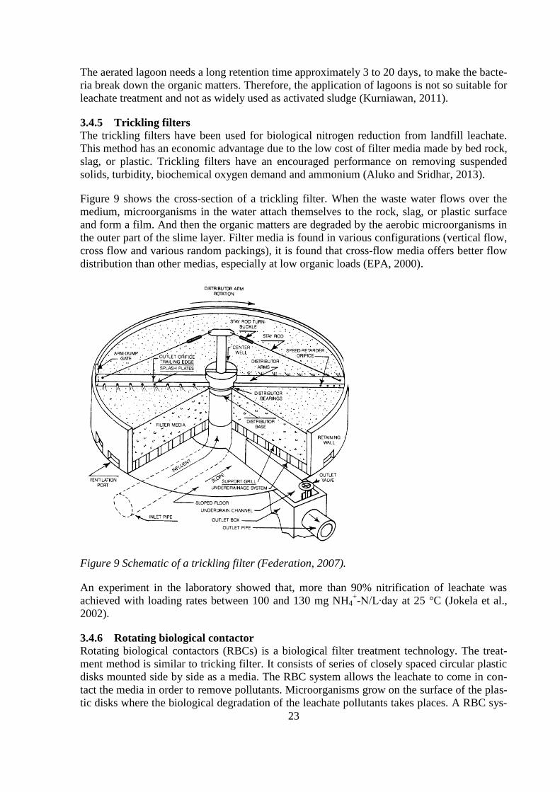
Figure 9 shows the cross-section of a trickling filter. When the waste water flows over the
medium, microorganisms in the water attach themselves to the rock, slag, or plastic surface
and form a film. And then the organic matters are degraded by the aerobic microorganisms in
the outer part of the slime layer. Filter media is found in various configurations (vertical flow,
cross flow and various random packings), it is found that cross-flow media offers better flow
distribution than other medias, especially at low organic loads (EPA, 2000).
Figure 9 Schematic of a trickling filter (Federation, 2007).
An experiment in the laboratory showed that, more than 90% nitrification of leachate was
achieved with loading rates between 100 and 130 mg NH4+-N/L∙day at 25 °C (Jokela et al.,
2002).
3.4.6 Rotating biological contactor
Rotating biological contactors (RBCs) is a biological filter treatment technology. The treat-
ment method is similar to tricking filter. It consists of series of closely spaced circular plastic
disks mounted side by side as a media. The RBC system allows the leachate to come in con-
tact the media in order to remove pollutants. Microorganisms grow on the surface of the plas-
tic disks where the biological degradation of the leachate pollutants takes places. A RBC sys-

24
tem is usually installed in a concrete tank so that the surface of the leachate passing through
the tank will reach the shaft which means about 40-50% of the total surface area of the disks
is submerged. When the disk continues to rotate, oxygen is transferred from the air to the me-
dia slime to remove the substances (Cooke, n.d.). For most systems, the rotation speed is ap-
proximately 2 rpm for a 3 m diameter distance. The RBC system is suitable used for the
treatment of low strength leachate (Kurniawan, 2011).
Normally, one single contactor is not sufficient to reach the high efficiency. Therefore, nor-
mally there are several contactors used in the RBC system. Most RBC systems consist of two
or more contactors that connect together. Figure 10 is leachate treatment system using three of
rotating biological contactors. This system has the advantages of low energy consumption for
aeration and less space occupation. However, clogging is a limitation for high strength leach-
ate in the system that affects the application of RBC. Experiments show that the result of
NH4+-N removal by using rotating biological contactor is about 95% with an initial NH4
+-N
concentration of 400 mg/L and COD removal is 86% with an initial COD concentration of
9,254 mg/L (Kurniawan, 2011).
Figure 10 Rotating biological contactors (Cooke, n.d.).
3.4.7 Biological aerated filters (BAFs)
Biological aerated filters are a biofilm system used for secondary and tertiary biological
treatment. It consists three phases: solids media that can provide surface for microbial growth;
a liquid phase where the solids are submerged; a gas phase is air input to the reactor. The sol-
ids media has a small size to provide the biggest surface area for the biomass. There are up-
flow BAFs and downflow BAFs depending on the design specified by the manufacturer (Es-
pinosa and Stephenson, 1999).

25
Figure 11 Upflow and Downflow BAF (Espinosa and Stephenson, 1999).
In upflow BAF, the wastewater is introduced at the bottom of the filter. The flow direction of
wastewater is the same as the air. Comparing to the downflow BAF, upflow filters have long-
er operational cycling systems and can decrease odour problem occurring since the atmos-
pheric air only contacts with treated effluent at the top of BAF. Downflow BAF has the oppo-
site direction as upflow BAF. It introduces wastewater from the top of filters and applies air at
the bottom. The downflow BAF has efficient mass transfer of oxygen to biofilm in the reactor.
Therefore, the nitrifying microorganisms usually can be found at the bottom where it will not
suffer from oxygen limitation (Pramanik et al., 2011).
Research shows that the ammonium removal of BAFs system was 97% at pH 7.2, 33% when
there was no pH control. There was little conversion to total oxidized nitrogen when pH was
9.2. From the efficient numbers, it seems that BAF can be used to nitrifying landfill leachate
(Stephenson et al., 2004).
3.4.8 Moving bed biofilm reactors (MBBR)
The moving bed biofilm reactors are techniques for having attached biomass in the reactor on
suspended porous polymeric carriers. The biomass is placed on small plastic carriers which
can have large surface for the biomass to grow. This method overcomes the disadvantage of
clogging problems that will happen in trickling filters, and the method has a higher biomass
concentration, lower sensitivity to toxic compounds and no long sludge settling period com-
pared to conventional suspended-growth processes (Renoua et al., 2008).
The MBBR system is shown in Figure 12. The bacteria grow on the internal surface of the
carriers and break down the organic matters. The aeration keeps the carriers in motion. The
diagram has two aerobic stages, but is flexible depending on the specific demands.

26
Figure 12 A MBBR system (Colloide, n.d.).
MBBR system can have a 85% - 90% ammonium reduction and 60% - 81% COD reduction
performance (Horan et al., 1997).
3.4.9 Upflow anaerobic sludge blanket (UASB)
UASB process is an anaerobic treatment of wastewater and landfill leachate at a high effi-
ciency rate and short hydraulic retention time (HRT). It can treat leachate with COD concen-
trations of higher than 10,000 mg/L. The influent of leachate goes from the bottom of the sys-
tem and flow upward through a blanket of biologically formed granules. The pH of the system
should be maintained at 7.0 and recommended COD: N: P ration is 300:5:1. The temperature
is generally between 20 and 35℃. The chemical equation of the reaction in the system is:
(C6H10O5)n + nH2O → 3nCO2 + 3nCH4 (5)
The COD removal of UASB is normally higher than 70% at temperature 20 – 23 ℃, 80% at
temperature at 35 ℃. Some experiments show that high rate treatment at low temperature may
minimize the need for heating the leachate prior to treatment, and the treatment may produce
toxic substances (Abbas et al., 2009).
3.4.10 Anaerobic filter
Anaerobic filter is a rock-filled bed similar to an aerobic trickling filter. There are upflow
anaerobic filters and downflow anaerobic filters. When the leachate influent is charged from
the bottom of the anaerobic filters and the flow is upward through the bed rocks, it is called
upflow anaerobic filters. Otherwise, it is downflow anaerobic filters. In the spaces of the rocks,
the anaerobic microorganisms accumulate in order to let the wastewater contact with a large
active biological mass. The anaerobic filter has some advantages compare to other biological
treatment methods: it is suitable for treating some soluble wastes, no effluent or solids recycle
is required; no strict temperature is require and low volumes of sludge produced (Young and
McCarty, 1969). Figure 13 shows upflow and downflow anaerobic filters.

27
Figure 13 Upflow and downflow anaerobic filters (Irwin, n.d.).
An experiment by Wang and Banks (2007) shows that the performance of the anaerobic filter
is good. The COD removal was ranging from 75 to 90% until the nominal retention time in
the reactor was 3 days, and sulphate removal is 88%.
3.4.11 Constructed wetland and reed beds
Considering the environmental and economic aspects, constructed wetlands are well accepted
for the treatment of landfill leachate. It acts as a natural biofilter with vegetations, removing
solids and heavy metals from the wastewater. The vegetations in the wetlands allow the natu-
ral attenuate contaminants in a passive mode with microorganisms (Kurniawan, 2011).
In general, constructed wetlands have the benefits of low cost technology and simple con-
struction. They have a high COD removal performance. But for the removal of NH4+-N, the
efficiency is poor (Klomjek and Nitisoravut, 2005).
Reed beds are an artificial impermeable layer with emergent hydrophytes, like reeds, bulrush
or cattails. Reed beds are using crushed stone for the inlet and outlet zones where the landfill
leachate can pass through. The biological processes will react in the pathway of the leachate.
It is similar to an aerated process. Aerobic bacteria grow in the reed beds to oxidize organic
matters (Ifeanyichukwu, 2008).
The reed beds are cheap to operate, have very low energy consumption, and very environmen-
tally friendly. However, there are some drawbacks. People should always caution against the
overland flow of reed beds, and when cold weather comes, the roots will freeze.
An experiment shows a 50% COD removal, and 51% ammonium nitrogen removal perfor-
mance of leachate (Tjasa, 2006).

28
3.4.12 Leachate recirculation
The landfill itself is an anaerobic biological reactor. Therefore, the leachate can be recycled
back to the landfill and react with microorganisms. The treatment accelerates the stabilization
of solid waste through microbial activities and decreasing the decomposition period from dec-
ades to 2-3 years.
This method provides benefits of low cost, simple operation, pH buffering, the moisture con-
tent increased, and reducing the volume of organic concentration in the leachate.
However, it could increase the concentration of leachate and affects toxic problems on meth-
anogenic bacteria. Also, leachate recirculation could not be applied into cold weather (Kur-
niawan, 2011).
3.4.13 Treatment performance of biological methods
For investigating the performance of each biological treatment method, some experiments
were made in terms of pH, HRT (days), OLR (kg/m3∙day) and initial concentration of COD
and NH4+-N (mg/L) in the landfill leachate (Kurniawan, 2011). Table 6 shows the most out-
standing performance of biological methods for removing COD and NH4+-N.
Table 6 Performance of outstanding biological methods (Kurniawan, 2011).
Type of
treatment
Location HRT
(day)
Volume of
leachate in
reactor (L)
Initial concentration
in leachate (mg/L)
Loading rate
(kg/m3∙day)
BOD5/
COD
Optimum
pH
Removal
efficiency (%)
COD NH4+-N COD NH4
+-N COD NH4+-N
Activated
sludge
NA 20 NA 24,000 790 1.2 NA 0.5 6.0-7.5 98 99
SBR Istanbul 1 5 26,000 1,000 120 0.58 NA 7.5 97 99
Nitrification Kyungjoo 3-4 20 26,940 1,810 15.2 0.84 NA 6-8.8 90 NA
Aerated
lagoons
Bryn NA - 9,750 175 NA NA 0.72 6.3 98 99.5
UASB Izmir 4.5 2.5 20,000 679 16 16 NA 7.0-7.3 98 99.6
From the table, it seems that the aerated lagoon, activated sludge, SBR and UASB have the
most outstanding performance for removal of COD and NH4+-N. The efficiency almost reach-
es 100%.
The selection of the most suitable method for landfill leachate depends on the characteristics
of the leachate, technical applicability, potential constraints, effluents limit required, cost-
effectiveness, regulatory requirements and long term environmental impacts (Kurniawan et al,
2006). Therefore, there is no absolute the best treatment method for leachate.

29
4 Description of Hedeskoga and Måsalycke
4.1 Introduction
Måsalycke and Hedeskoga are landfills both belonging to the waste company SYSAV. The
company is a Swedish waste company which focuses on collecting households and business
waste in southern Skåne. SYSAV is owned by 14 municipalities with a joint population over
700,000 and has about 6,000 corporate costumers (SYSAV, 2013).
Figure 14 shows the locations of these two sites.
Figure 14 Hedeskoga (Green B) and Måsalycke (red A) (Google Map, 2013).
4.1.1 Hedeskoga
Hedeskoga landfill is located in Ystad, southern Sweden. The landfill was established in 1973
with waste from a total population of 55,000. The landfill size is 21 hectares (ha). Of geologic
consideration, the Hedeskoga landfill was located on a bed of limestone and sandstone depos-
ited during the late Tertiary and the early Cretaceous periods. 10 – 15 meters below the land-
fill bottom is the solid rock. The landfill receives municipal solid waste (MSW), industrial,
commercial and institutional waste (IC&I). Until 2003, the annual production of leachate was
approximately 50,000 m3
– 70,000 m3 and most of the leachate was collected in early spring
and late autumn (Thörneby et al., 2003).
Nowadays, there are two leachate collection systems in Hedeskoga, the original one that col-
lects leachate from the old part and a new one that collects leachate from the new landfill and
a small part from the old landfill.

30
4.1.2 Måsalycke
Måsalycke is located in S:t Olof, southern Sweden, approximately 40 kilometers away from
Hedeskoga. The landfill was established in 1975 with a landfill size of 9 ha (SYSAV, 2012).
Due to new regulations on landfill construction, the landfilling stopped by the end of 2008
and the landfill is now being covered in order to meet the regulations. At first, the shape of the
landfill was very hilly. Therefore, they had to flatten the landfill. Now they are working on the
top material for the landfill. Several possibilities have been discussed for cover materials of
the landfill, plastics, clay and other impermeable layers.
4.2 Leachate treatment
4.2.1 Hedeskoga
In 2012, the total collected leachate volume was 106,000 m3. Appendix 1 and 2 shows the
compound concentrations in 2012 from the old leachate pond L1 and new leachate pond P5B.
In the early 1990s, the ratio of BOD and COD was a bit over 0.1, however until 2003, it de-
creased to below 0.1. In 2002, the ratio decreased to approximately 0.06. This indicates that
the Hedeskoga landfill is in the methanogenic phase (Thörneby et al., 2003). The leachate
from the new part is much less diluted than the leachate from the old part, for instance, higher
conductivity and nitrogen content.
The treatment system in Hedeskoga contains one new collection pond (P5B) and one old pond
(L1). The old pond has two small ponds which both receive leachate. Smaller ponds may offer
an advantage in reducing construction and desludging costs (excavators and agitators have a
limited reach) (Birchall et al., 2008). The treatments of Hedeskoga contain aeration and sedi-
mentation. The new leachate will go to the old storage pond and is mixed with the old leach-
ate. The retention time is six to seven days before the mixture will be transferred to another
storage pond. From the second pond the well with mixed leachate will be pumped into the
aeration pond and then to sediment pond. After the aeration/sedimentation the leachate is used
for irrigation in the growth season, if the storage capacity is too small, leachate can be trans-
ferred to the municipal waste water treatment plant in Ystad, as a final solution. The process
is shown in Figure 15.

31
Figure 15 Treatment process in Hedeskoga (Sha Liu, 2013).
4.2.2 Måsalycke
The amount of collected leachate in Måsalycke landfill was 26,800 m3 in 2012 (SYSAV,
2012).
The treatment process is shown in Figure 16. At Måsalycke landfill, there is one storage pond
and one aeration pond, the aeration pond works as an aeration pond and as a sediment pond.
In different parts of the landfill there are several cylindrical storages which collect the leach-
ate. The collected leachate is then pumped into a storage pond which is shown in Figure 16
and after that in to an aeration pond for nitrification and sedimentation. Then the treated
leachate will be led to a sand filter nearby and after that used for irrigation or filtration. The
irrigation takes place in the growth season and is conducted in two different zones, one with
normal trees and one with nettles. If the storage capacity is too small, it is possible to infiltrate
leachate into a bog.
In Sweden, there is no specific criterion to be followed for landfills, each landfill has its own
regulations and limitations. If the effluent does not affect the growth of the irrigation zone,
staff of Måsalycke and Hedeskoga landfills assumes that the effluent of the wastewater treat-
ment reaches the standards of the discharged leachate.

32
Figure 16 Landfill leachate treatment processes in Måsalycke (Sha Liu, 2013).
4.3 Situation of today
4.3.1 Hedeskoga
In Hedeskoga, the outflow from the aeration ponds has a high concentration of ammonium.
The raw leachate in the new leachate collection pond is more concentrated than the old one.
In order to reduce the quantities and improve the quality of the leachate, SYSAV operated
several experiments for the Hedeskoga landfill: increased irrigation surface areas, diverted
surface water to the surrounding wetlands and cleaning of all collection ponds. The perfor-
mance of these actions decreased leachate disposal successfully in 2012 compared to 2011
(SYSAV, 2012).
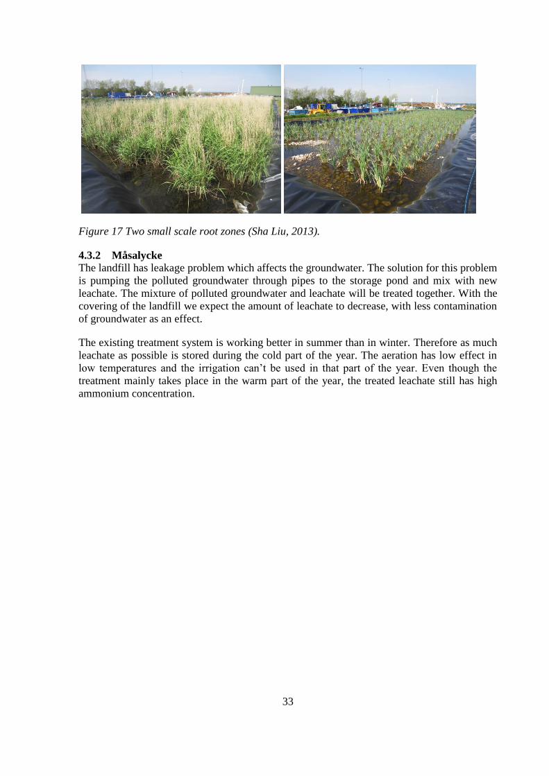
In 2012, SYSAV operated an experiment for discharge of treated leachate. Researchers oper-
ated two small scale wetlands planted with two different kinds of plants. These two zones are
shown in Figure 17. It has only been going on for one year and it is too early to draw conclu-
sions about the performance. Future observations are needed in order to fully evaluate the
approach.
33
Figure 17 Two small scale root zones (Sha Liu, 2013).
4.3.2 Måsalycke
The landfill has leakage problem which affects the groundwater. The solution for this problem
is pumping the polluted groundwater through pipes to the storage pond and mix with new
leachate. The mixture of polluted groundwater and leachate will be treated together. With the
covering of the landfill we expect the amount of leachate to decrease, with less contamination
of groundwater as an effect.
The existing treatment system is working better in summer than in winter. Therefore as much
leachate as possible is stored during the cold part of the year. The aeration has low effect in
low temperatures and the irrigation can’t be used in that part of the year. Even though the
treatment mainly takes place in the warm part of the year, the treated leachate still has high
ammonium concentration.

34

35
5 Inhibition of nitrification
The nitrification process is depending on the nitrifiers ability to oxidize ammonium to nitrate
(Anthonisen et al., 1976). Some factors may affect the nitrification rate, such as ratio of car-
bon to nitrogen, temperature, pH, dissolved oxygen and toxic compounds (中大网校, 2009).
In the nitrification process, the ratio of carbon and nitrogen affects the growth of nitrifiers.
There will be fewer nitrifiers in the activated sludge when the ratio becomes high.
The temperature will impact both the growth and the activities of nitrifiers. The suitable tem-
perature for nitrification is about 30-35 ℃ and 20-40 ℃ for denitrification process.
The nitrification process is happened in an oxidized environment which the dissolved oxygen
is suggested to be over 2 mg/L. In the nitrification process, to oxidize 1g ammonium needs
7.14 g alkalinity. The pH decreases in the reaction which will impact nitrifiers rapidly. Hence,
the optimum pH for nitrification is 7.5-8.5.
High concentration of ammonium, heavy metals and toxic substances will affect nitrification
in two ways, one is to interfere the cell’s metabolism and another is to destroy the oxidizing
capacity of the bacteria (中大网校, 2009).
5.1 Methodology
The inhibition of nitrification is the decrease in nitrification rate in a test tube containing acti-
vated sludge, nutrients, buffer and test substances compared to the nitrification rate of a refer-
ence test tube with tap water added instead of the test substance (Jönsson, 2013).
The methodology for the inhibition test used in this study is the screening method. It is an
efficient way to determine the short term inhibitory effects of test substances on nitrifying
bacteria in activated sludge. This method is suitable for any types of waste water. It is appli-
cable to wastewater and chemical substances which are soluble. For insoluble substances,
they can be tested if care is taken to ensure as much as homogeneity as possible. The result of
this method may depend also on the characteristics of the activated sludge (Jönsson, 2013).
5.1.1 Relevant parameters, chemical symbols and formulas
Activated sludge: Accumulated biological mass (floc) produced in the treatment of
wastewater by the growth of bacteria and other microorganisms in the presence of dissolved
oxygen.
Total suspended solid (SS): The concentration of particles, suspended solids, expressed as
grams of dry matter per liter which is retained at a filter of specified pore size when a known
volume of suspension is filtered.
Volatile suspended solids (VSS): The concentration of volatile suspended solids is the organic
fraction of SS analyzed.
Substrate: Ammonium, carbonate and phosphate.
Activated sludge suspension: A mixture of activated sludge, substrates and tap water.

36
Test substances: wastewater, pure chemicals, mixtures or chemical products.
Oxidized nitrogen: NO2 + NO3 = NOx
Nitrification: Biological oxidation of ammonium per unit of time expressed as mgN/(g
VSS∙h).
NTS: the concentration of oxidized nitrogen in the test tubes (mgN/L)
NTT,0, NTT,end: the initial and the final concentration of oxidized nitrogen in the test tubes, re-
spectively (mgN/L)
NC,0 : the average concentration of oxidized nitrogen in the three controls with incubation time
0 hour (mgN/L)
VTS: the volume of the test substance added to the test tube (ml)
VTT, VSS: VTT is the total volume of liquids added to the test tube (= 10 ml), VSS is the volume
of sludge suspension added to the test tube (= 5 ml)
VSSTT,VSSSS: the concentration of suspended solids in the test tube and in the sludge suspen-
sion, respectively (gVSS/L)
RNITR., RNITR,C, RNITR,S: the nitrification rate, the average nitrification rate of the test tubes
containing tap water, the average nitrification rate of the test tubes containing test substance
(mgN/(gVSS∙h))
t: the incubation time (h)
I: the inhibition of nitrification (%)
△NH4: the decrease in the ammonium concentration during the test (mgN/L)
The needed formulas are listed below:
NTT,0 = NC,0 + NTS ∙ VSS/VTT (6)
VSSTT = VSSSS ∙ VSS/STT (7)
RNITR. = ( NTT,end – NTT,0)/t∙VSSTT (8)
I = (RNITR. - RNITR,S)/ RNITR,C∙100 (9)
△NH4 = RNITR. ∙ VSSTT ∙ t (10)
5.2 Experiment
5.2.1 SS of activated sludge
Taking 10 ml activated sludge for measuring the suspended solid (SS). The measurement is
made in triplicate. Table 7 shows the results.

37
Table 7 Parameters for measuring suspended solid.
Unit:
g
Paper
weight
Weight after
infiltration
Weight after
oven 105 ℃
Weight after
oven 550 ℃
SS (g/10 ml)
SS (g/L)
1
2
3
0.120
0.122
0.121
0.628
0.613
0.634
0.171
0.173
0.170
0.1316
0.1331
0.1317
0.051
0.051
0.049
5.1
5.1
4.9
℃
SS = ( )
The examples are 10 ml, after calculation, the average SS is 5.03 g/L.
5.2.2 Activated sludge suspension
The prepared activated sludge suspension should have a VSS concentration of 1.5-6 g/L, am-
monium concentration of 50 mg/L, bicarbonate concentration of 8 mM and a phosphate con-
centration of 10 mg PO4-P/L. The pH should be adjusted to 7.5 ± 0.5 (Jönsson, 2013).
The components that should be added to the solution are shown in Table 8.
Table 8 The nutrient and buffer to be added to the solution.
Component Content
Ammonium sulfate (NH4)2SO4
Sodium bicarbonate NaHCO3
Potassium dihydrogen phosphate KH2PO4
Distilled water
5.9 g
16.8 g
1.1 g
250 ml
As it is shown in Table 9, taking 10 ml of solution and mixes it with 790 ml activated sludge
and 200 ml tap water. The mixture liquid is 1 L activated sludge suspension.
Table 9 The component of activated sludge suspension.
Component Content
Activated sludge nutrient and buffer solution
Activated sludge
Tap water
10 ml
790 ml
200 ml
5.3 Results and analyses
Four different types of leachate were tested: P5B, L1 are the new leachate and old leachate in
Hedeskoga landfill, respectively. H (MIX) is the mixture of the new and old leachate. M is the
leachate from the Måsalycke landfill.
The nitrogen concentrations in the four leachates are shown in Table 10.

38
Table 10 Start conditions to the four types of leachates.
Sample pH pH-adjustment to pH Temp.
(°C)
NH4+-N
(mg/L)
NO2-N
(mg/L)
NO3-N
(mg/L)
P5B
L1
H(MIX)
M
7.88
6.86
7.83
7.76
7.58
20.0
21.0
19.8
19.6
93.3
129.5
96.8
109
4.47
0.096
1.04
0.23
3.91
4.465
12
0.935
The dilution of 50%, 20%, 10% and 5% were tested of each leachate. There are also six con-
trol samples needed for calculating the inhibition.
The inhibition of each leachate is in Table 11. It is ranging from 30% to -19%, and Figure 18
is the logarithmic chart of the inhibition.
Table 11 Inhibition of nitrification.
Dilution
(%)
Sample NOX-N,after,
avg."CX" (mg/L)
"Co"
(mg/L)
NOx-N
(mgNOx-N/(gVSS*h))
Inhibition
(%)
- Control 13.78 0.72 4.21 -
50
20
10
5
P5B 16.23
15.34
14.97
13.68
4.91
2.40
1.56
1.14
3.65
4.17
4.33
4.04
13
1
-3
4
50
20
10
5
L1 12.15
13.44
14.56
14.67
3.00
1.63
1.18
0.95
2.95
3.81
4.32
4.42
30
10
-3
-5
50
20
H(MIX) 22.78
15.73
7.24
3.33
5.01
4.00 -19
5
50 M 13.58 1.30 3.96 6

39
Figure 18 Inhibitions of the four types of leachate.
P5B which is the new leachate in Hedeskoga has nitrification inhibition when the dilution is
50%. The inhibition stops when the dilution drops to or below 20%. For the old leachate in
Hedeskoga, L1, the inhibition exists until the dilution is or below 20%, and stops when dilu-
tion is or below 10%.
At Måsalycke landfill, the value 6% shows there is almost no inhibition in the Måsalycke
landfill leachate.
However, one number should be paid attention is the example H (MIX) with a strange number
-19%. This high negative number was unpredicted. The reason for this may be due to the spe-
cial substances contain in the leachate which promote the nitrification rate.
-30
-20
-10
0
10
20
30
40
50
1 10 100Nit
rifi
cati
on
inh
ibit
ion
dilution (%)
L1
P5B
H
M

40

41
6 Discussion
The Hedeskoga and Måsalycke landfills have been operated for several years. The concentra-
tion of ammonium is still high in the effluent from the treatment ponds. It is an interesting
idea to speculate causes of the high concentration of ammonium nitrogen in effluent. There
are some suggested ideas of the causes, e.g. the pond capacity, toxic problems or environmen-
tal problems.
6.1 Limitations
All the data about the landfills have been provided by the company of SYSAV. The result of
inhibition experiment is assumed to be reliable. However, the practical situation in Hedesko-
ga and Måsalycke landfills could not be tracked all the time. Therefore, the proposed solu-
tions to the problems are mainly based on assumptions.
6.2 Proposed reasons for limited nitrification
6.2.1 Pond capacity
The suitable pond capacities of Hedeskoga and Måsalycke landfills, can be calculate based on
Karlsson (2011):
(
)
⁄ (12)
Where RT is the detention time (days) at temperature T, LP is the pond and effluent’s BOD
(mg/L), LO is the influent BOD (mg/L) and KT is breakdown rate at temperature T. KT value
varies of environmental temperature and can be found in Table 12.
(13)
Where V is the volume of the aerated pond (m3/d) and Q is the leachate flow (m
3).
Table 12 Biological breakdown rate (Karlsson et al., 2011).
Temperature (℃)
KT
5
0.103
10
0.12
15
0.24
20
0.35
25
0.53
30
0.80
35
1.2
The BOD removal of the aerobic pond can be assumed to be 80%, the average temperature in
Skåne is approximately 15 ℃ (Worldweather, 2013). So the KT value is 0.24 according to
Table 12.
(
)
⁄ =17 d
The detention time for leachate should be 17 days if BOD removal reaches 80%.
In Hedeskoga landfill, the annual leachate collected volume is 50,000 to 60,000 m3 which
gives an average flow of 150 m3/d. According to formula (13), the volume of aeration tank

42
should be 2550 m3. Now the aeration volume of aerobic tank is 5000 m
3 which means that the
pond capacity is big enough.
At Måsalycke landfill, the total leachate collected volume was 26,800 m3 in 2012 which gave
an average flow of 73.4 m3/d. The volume of aeration tank then should be 1248 m
3. The aera-
tion volume of the aerobic tank is 3000 m3 which means that the pond capacity is big enough.
6.2.2 Toxic problem
To determine leachate toxicity both toxicological and chemical characterizations is required.
Toxicological approach with endpoints on population, community or ecosystem level should
be used for environmental risk assessments (Berglund, n.d.). Because of lack of data, toxico-
logical method could not be used to analyze the problems. Therefore, the analysis of the toxic
problem is based on the treatment results of Hedeskoga and Måsalycke landfills (Appendix 3)
and inhibition test.
As it is shown in Appendix 3, in Hedeskoga, the treatment result shows high ammonium con-
centrations, high total nitrogen concentrations and high COD in the effluent. All heavy metal
parameters are below the standards. The inhibition test indicates that there was inhibition in
the old and new leachate in Hedeskoga. But in the mixed leachate, some substances increased
the nitrification rate and there was no inhibition. In general, there is nitrification toxicity in the
old and new leachate ponds in Hedeskoga landfill, but there is no nitrification toxicity in the
mixed leachate.
At Måsalycke landfill, the treatment performance is reasonable compared to Hedeskoga. The
total nitrogen of effluent from aeration pond was under the standard 70 mg/L (ANONYMUS,
1996). The ammonium concentration is a little bit high, but the trees and nettles grown well
after years of irrigation. From the inhibition test, no inhibition is seen. Therefore, an assump-
tion can be made that Måsalycke has no toxic problems.
6.2.3 Environmental problem
The water temperature is a dominating factor for the nitrification process. The cold climate
restrains the sensitivity of nitrifiers, and then affects the nitrification performance. Hedeskoga
and Måsalycke landfills are located in southern Sweden. The air temperature is usually below
-10 ℃ in winter and sometimes even below -20 ℃. At Måsalycke landfill, the aeration has
low effect in low temperatures and the irrigation cannot be used in that part of the year.
Therefore, the temperature could be a reason which causes the high ammonium concentration
of effluent only in Hedeskoga landfill.
The pH value is another factor which will affect the nitrification. The optimum pH for nitrifi-
cation is 7.5-8.5, but some treatment plants are able to effectively nitrify with a pH of 6.5 to
7.0. According to the Appendix 1, 2 and 3, the average pH of non-treated leachate is around
7.3 in Hedeskoga landfill and 6.7 in Måsalycke landfill.
Hence, pH should not be a problem for Hedeskoga landfill. The pH in Måsalycke landfill is
over 6.5 slightly which is in the ranges. So pH should not be a problem in Måsalycke landfill,
either.

43
6.3 Recommendations
Considering the practical situation of Hedeskoga and Måsalycke landfills, some treatment
methods can be recommended.
The main idea for choosing treatment methods is to reduce the concentration of ammonium.
This process occurs during nitrification which turns ammonium to nitrite and nitrate. Some
leachate treatment methods have good performance for removal ammonium in leachate, e.g.
activated sludge, aerated lagoon, rotating biological contractor, ammonia stripping and se-
quencing batch reactor, trickling filters, biological aerated filters, moving bed biofilm reactors.
However, for some limitations, some of these methods are not suitable for leachate treatment.
Ion exchange, ammonia stripping and electrochemical treatment are not recommended be-
cause of the high operating cost. Lagoons have a relative long retention time which is not rec-
ommended. An experiment was done by Guo Jian (1998) indicates that it is possible to have a
high removal performance for ammonium nitrogen at low operating temperature 4 ℃ by us-
ing activated sludge system. The result of the experiment had a more than 90% ammonium
nitrogen removal performance.
Therefore, rotating biological contractor, activated sludge, trickling filters, BAF, MBBR and
SBR system could be used for the treatment of Hedeskoga and Måsalycke landfills. Also, a
combined system with physical/chemical and biological systems can be used in leachate
treatment. For instance, chemical precipitation can be used as pre-treatment combined with
activated sludge or SBR system in order to remove high concentration of ammonium nitrogen.

44

45
7 Conclusions
Two landfills, Hedeskoga and Måsalycke have been evaluated in this thesis.
The reasons for the high ammonium concentration in Hedeskoga landfill are the toxic prob-
lems and cold weather. It means that the initial concentration of ammonium inhibited the nitri-
fication process. Low temperature restrains the sensitivity of nitrifiers, thereby reducing the
nitrification performance.
In general, to evaluate the different treatment methods for landfill leachate, rotating biological
contractor, activated sludge, trickling filters, BAF, MBBR and SBR system could be used for
the treatment of Hedeskoga and Måsalycke landfills.

46
47
8 References
Abbas Abdulhussain A., Jingsong Guo, Zhi Ping Liu, Ying Ya Pan and Wisaam S. Al-Rekabi,
2009. Review on Landfill Leachate Treatments. American Journal of Applied Sciences, 6(4),
pp. 672-684.
Alcamo J., Henrichs T. and Rösch T., 2000. World Water in 2025, center for environmental
systems research, University of Kassel.
Aluko OO and Sridhar MK, 2013. Evaluation of leachate treatment by trickling filter and
sequencing batch reactor processes in Ibadan, Nigeria. Waste Manag Res., 31(7), pp. 700-705.
Alvarez-Vazquez Héctor, Jefferson B. and Simon J. Judd, 2004. Membrane bioreactors vs
conventional biological treatment of landfill leachate: a brief review. Journal of Chemical
Technology & Biotechnology, 79(10), pp. 1043 - 1049.
ANONYMUS, 1996. Anhang 51: Oberirdische Ablagerung von Abfällen. Allgemeine
RahmenVerwaltungsvorschrift über Mindestanforderungen an das Einleiten von Abwasser in
Gewässer, s.l.: German regulation.
Anthonisen A. C., Loehr R. C., Prakasam T. B. S. and Srinath E. G., 1976. Inhibition of
Nitrification by Ammonia and Nitrous Acid. Water Pollution Control Federation, 48(5), pp.
835-852 .
Berglund O., n.d. Leachate ecotoxicity - characterization and risk assessment, Lund: Lund
University.
Birchall S., Coomes Consulting Group, Cliff Dillon, Wrigley Dillon, Roger Wrigley, 2008.
Effluent and Manure Management Database for the Australian Dairy Industry. s.l.:Dairy
Australia
Björklund A., Johansson J., Nilsson M., Eldh P., Finnveden G., 2003. Environmental
Assessment of a Waste Incineration Tax Case Study and Evaluation of a Framework for
Strategic Environmental Assessment. Stockholm: Division of Defence Analysis.
CARBTROL, 1992. GRANULAR ACTIVATED CARBON FOR WATER & WASTEWATER
TREATMENT CARBTROL [Online] Available at: http://www.carbtrol.com/water&waste.pdf
[Accessed August 2013].
Carville M., 2013. Waste management world. [Online] Available at: http://www.waste-
management-world.com/articles/2005/11/leachate-treatment.html [Accessed 2013].
Chen Guohua, 2004. Electrochemical technologies in wastewater treatment. Separation and
Purification Technology, 38(1), p. 11–41.
Choo Kwang-Ho and Lee Chung-Hak, 1996. Membrane fouling mechanisms in the
membrane-coupled anaerobic bioreactor. Water Research, 30(8), p. 1771–1780.

48
Clark L., 2012. Sweden to import 800,000 tonnes of trash to burn for energy. WIRED, 29th
October. [Online] Available at: http://www.wired.co.uk/news/archive/2012-10/29/sweden-
imports-garbage-for-energy [Accessed September 2013].
Colloide, n.d. Colloide Engineering Systems Ltd. MOVING BED BIO - REACTOR SYSTEM
(MBBR) [Online] Available at: http://www.colloide.com/manager/images/uploads/Moving-
bed-bio-reactor-technology-MBBR.pdf [Accessed 2013].
Connolly R., Yaqian Zhao, Guangzhi Sun, Stephen Allen, 2004. Removal of ammoniacal-
nitrogen from an artificial landfill leachate in downflow reed beds. Process Biochemistry,
39(12), pp. 1971-1976.
Cooke Rosa-lee, n.d. Mountain empire community college. [Online] Available at:
http://water.me.vccs.edu/courses/env110/lesson16.htm [Accessed August 2013].
Crutcher A. J., Yardley J. R., 1992. Implicactions of changing refuse quatities and
characteristics on future landfill design and operations. In Municipal Solid Waste
Management. Edited by M.E, HAIGHT. Waterloo, Ont. University of Waterloo Press.
Dabrowski A., Hubicki Z., Podkościelnya P., Robensb E., 2004. Selective removal of the
heavy metal ions from waters and industrial wastewaters by ion-exchange method.
Chemosphere, 56(2), pp. 91-106.
Diamadopoulos E., 1994. Characterization and treatment of recirculation-stabilized leachate.
Water Research, 28(12), p. 2439–2445.
Ehrig H. J., 1983. Quality and Quantity of Sanitary Landfill Leachate. Waste Manage Res,
Volume 1, pp. 53-68.
EPA, 2000. Wastewater Technology Fact Sheet: Ammonia Stripping, Washington D.C.:
Environmental protection agency.
EPA, 2000. Wastewater technology fact sheet: trickling filters, Washington D.C.:
Environmental protection agency.
Espinosa L. M. and Stephenson T., 1999. A view of biological aerated filters (BAFs) for
wastewater treatment. Environmental engineering science, 16(3).
European Commission, 1999. Council Directive 1999/31/EC on the landfill of waste. Official
Journal L 182, pp. 0001-0019.
Eurostat, 2012. Municipal waste generation and treatment, by type of treatment method,
Eurostate. [Online] Available at:
http://epp.eurostat.ec.europa.eu/tgm/table.do?tab=table&init=1&language=en&pcode=tsdpc2
40&plugin=1 [Accessed September 2013].
Federation W. E., 2007. Operation of Municipal Wastewater Treatment Plants. 6th Edition ed.
s.l.:WEF Press.
Google Map, 2013. google. [Online] Available at: maps.google.se
[Accessed 2013].

49
Guo Jian, 1988. Low temperature biological treatment of a high ammonia municipal landfill
leachate, s.l.: s.n.
Gurijala K. Rao and Suflita Joseph M., 1993. Environmental factors influencing
methanogenesis from refuse in landfill samples. Environ. Sci. Technol., 27(6), p. 1176–1181.
Heimlich Joe E., Hughes Kerry L. and Christy Ann D., n.d. The Ohio State University.
[Online] Available at: http://ohioline.osu.edu/cd-fact/pdf/0106.pdf
[Accessed July 2013].
Horan N., Gohar H. and Hill B., 1997. Application of a granular activated carbon-biological
fluidised bed for the treatment of landfill leachates containing high concentrations of
ammonia. Water Science and Technology, 36(2-3), p. 369–375.
Huang C. P., Chengdi Dong, Zhonghung Tang, 1993. Advanced chemical oxidationAdvanced
chemical oxidation:Its present role and potential future in hazardous waste treatment.
sciencedirect, 13(5-7), pp. 361-377.
Ifeanyichukwu M. J., 2008. New leachate treatment methods, s.l.: Lund University.
Irwin T., n.d. Engineeringfundamentals. [Online] Available at:
http://www.engineeringfundamentals.net/AnaerobicFilters/fundamentals.htm [Accessed
September 2013].
Johannessen Lars Mikkel, n.d. Guidance note on leachate management for municipal solid
waste landfills, [Online] Available at:
http://www.worldbank.org/urban/solid_wm/erm/CWG%20folder/uwp5.pdf [Accessed
September 2013].
Jokela J., Kettunen R., Sormunen K. and Rintala J., 2002. Biological nitrogen removal from
municipal landfill leachate: low-cost nitrification in biofilters and laboratory scale in-situ
denitrification. Water Research, 36(16), p. 4079–4087.
Jönsson K., 2013. Screening method for determination of inhbition of nitrificetion of activated
sludge, s.l.: Lund University.
Karlsson Lina, Liu Xiaoyue and Jewitt Nicholas, 2011. Waste Stabilization/Treatment Ponds.
Lund:Lund University.
Kjeldsen Peter, Morton A. Barlazb, Alix P. Rookerb, Anders Bauna, Anna Ledina and
Thomas H. Christensena, 2002. Present and long-term composition of MSW landfill leachate:
A review. Critical Reviews in Environmental Science & Technology, 32(4), pp. 297-336.
Klomjek P. and Nitisoravut S., 2005. Constructed treatment wetland: a study of eight plant
species under saline conditions. Chemosphere, 58(5), p. 585–593.
Kochmembrane, 2013. Membrane Filtration Technology: Meeting Today’s Water Treatment
Challenges. [Online] Available at: http://www.kochmembrane.com/PDFs/Membrane-
Filtration-Technology---Koch-Membrane-Sys.aspx [Accessed 2013].

50
Kurniawan Tonni Agustiono, 2011. Treatment of Landfill Leachate. s.l.:LAP LAMBERT
Academic publishing GmbH and Co.KG.
Kurniawan Tonni Agustiono, Chan GY, Lo WH, Babel S., 2006. Comparison of low-cost
adsorbents for treating wastewater laden with heavy metals. Sci Total Environ, 366(2-3), pp.
409-426.
Lenntech, n.d. Schematic Diagram of Activated-Sludge Process. [Online] Available at:
http://www.lenntech.com/wwtp/wwtp-activated-sludge-process.htm [Accessed September
2013].
Lina Karlsson, Xiaoyue Liu and Nicholas Jewitt, 2011. Waste stabilization/ treatment ponds:
aerobic and anaerobic water treatment. Lund: Lund University.
Majone Mauro, Marco Petrangeli Papinia, Enrico Rolleb, 1998. Influence of metal speciation
in landfill leachates on kaolinite sorption. Water Research, 32(3), p. 882–890.
Milios L., 2013. Municipal waste management in Sweden. European environment agency.
Montague P., 1982. Hazardous Waste Landfills: Some Lessons from New Jersey. Civil
Engineering—ASCE, 52(9), pp. 53-56.
Mårtensson A.M., Aulin C., Wahlberg O. and Ågren S., 1999. Effect of humic substances on
the mobility of toxic metals in a mature landfill. Waste Manag Res., 17(4), pp. 296-304.
Pramanik B. K., Fatihan S., Shahrom Z. and Ahmed E., 2011. Biological aerated filters
(BAFs) for carbon and nitrogen removal: A review. Engineering science and technology, 7(4),
pp. 428-446.
Proceco, 2012. Ultrafiltration (UF) Systems for Wastewater Treatment and Recycling.
[Online] Available at: http://www.proceco.com/products/wastewater-treatment/Wastewater-
Treatment-Ultrafiltration.php [Accessed 2013].
Prüss-Üstün Annette, Robert Bos, Fiona Gore and Jamie Bartram, 2008. Safer Water, Better
Health: Costs, benefits, and sustainability of interventions to protect and promote health.
Edition. World Health Organization. ISBN: 9789241596435
Renoua S., Givaudan J.G., Poulain S., Dirassouyan F., Moulin P., 2008. Landfill leachate
treatment: Review and opportunity. Journal of Hazardous Materials, 150(3), pp. 468-493.
Roux G. le, n.d. Guidelines for leachate control. [Online] Available at:
http://www.dwaf.gov.za/Documents/Policies/WDD/LeachateControl.pdf [Accessed 2013].
Rubio J., M.L. Souza and R.W. Smith, 2002. Overview of flotation as a wastewater treatment
technique. Minerals Engineering, 16(3), p. 139–155.
Sarasa J, Llabrés T, Ormad P, Mosteo R, Ovelleiro JL, 2006. Characterization and photo-
Fenton treatment of used tires leachate. Journal of hazardous material, 136(3), pp. 874-881.

51
SEPA, 2002. SEPA. [Online] Available at:
http://www.sepa.org.uk/waste/waste_regulation/idoc.ashx?docid=1aefd2f4-b7cc-48e0-b301-
5dae0cbc6f60&version=-1 [Accessed 16th May 2013].
SOLMAX, 2012. Waste landfills: non-hazardous and hazardous technical notes, SOLMAX.
[Online] Available at: http://www.solmax.com/wp-
content/uploads/2012/09/WasteLandfillsNote-english.pdf [Accessed 2013].
Stephenson T, Pollard SJ, Cartmell E, 2004. Feasibility of biological aerated filters for
treating landfill leachate. Environmental Technology, 25(3), pp. 349-354.
Steve Last, 2011. The Five Golden Rules for Successful Leachate Management. [Online]
Available at: http://leachate.co.uk/5-Golden-Rules-of-Leachate-Management.pdf [Accessed
2013].
Stig Morling, 2008. Swedish Experiences of Landfill Leachate Treatment Using Sequencing
Batch Reactors, s.l.: Royal Institute of Technology, STOCKHOLM;SWEDEN;SWECO
VIAK AB.
Svensktvatten, 2013. Svensktvatten. [Online] Available at:
http://www.svensktvatten.se/Vattentjanster/Avlopp-och-Miljo/REVAQ/om-REVAQ/
[Accessed 28 May 2013].
SYSAV, 2012. Hedeskoga avfallsanläggning:Miljörapport för år 2012, s.l.: SYSAV.
SYSAV, 2012. Måsalycke avfallsanläggning:miljörapport för år 2012, s.l.: SYSAV.
SYSAV, 2013. SYSAV. [Online] Available at: www.sysav.se [Accessed June 2013].
Tchobanoglous G., Burton F. L. and Stensel H. D., 2002. Wastewater Engineering: Treatment
and Reuse. 4th edition ed. s.l.:McGraw-Hill Science/Engineering/Math.
Thörneby L., William Hogland, Jan Stenis, Lennart Mathiasson and Pernilla Somogyi, 2003.
Design of a reverse osmosis plant for leachate treatment aiming for safe disposal. Waste
Manag Res, 21(5), pp. 424-435.
Tjasa G. Bulc, 2006. Long term performance of a constructed wetland for landfill leachate
treatment. Ecological Engineering, 26(4), p. 365–374.
URS, 2001. Final report: Basis for Landfill Classification System. [Online] Available at:
http://www.mfe.govt.nz/publications/waste/basis-landfill-classification-nov01.pdf [Accessed
June 2013].
Wang B, He S, Wang L, Shuo L, 2005. Simultaneous nitrification and de-nitrification in
MBR. Water Sci Technol, 52(10-11), pp. 435-442.
Wang Z. and Banks C.J., 2007. Treatment of a high-strength sulphate-rich alkaline leachate
using an anaerobic filter. Waste Manag, 27(3), pp. 359-366.

52
Water technologies and development, n.d. Water technologies and development. From design
to production [Online] Available at: http://www.t-and-d-italy.com/products/wastewater/sbr-
plants/ [Accessed September 2013].
Waterworld, n.d. Membrane Filtration for Wastewater Reuse Current [Online] Available at:
http://www.waterworld.com/articles/wwi/print/volume-25/issue-5/regional-spotlight/north-
american-caribbean/membrane-filtration-for-wastewater-reuse-current.html [Accessed
September 2013].
WHO (World Health Organization), 2012. Global Analysis and Assessment of Sanitation and
Drinking-water (GLAAS): The challenge of extending and sustaining services. UN-water
global annual assessment of sanitation & drinking-water. Edition. World Health Organization.
ISBN: 9789241503365
Wiszniowski J., D. Robert, J. Surmacz-Gorska, K. Miksch, J. V. Weber, 2006. Landfill
leachate treatment methods: A review. Environmental Chemistry Letters, 4(1), pp. 51-61.
Worldweather Online, 2013. Average High/Low Temperature for Skane, Sweden. [Online]
Available at: http://www.worldweatheronline.com/Skane-weather-averages/Varmlands-
Lan/SE.aspx [Accessed October 2013].
Wroblewski C., Smith A., Zimmerman B. and Gentz, F., n.d. Waste management alternatives.
[Online] Available at: https://sites.google.com/site/wastemanagementalternatives/types-of-
landfills [Accessed September 2013].
Yalmaz G. and Oztürk I., 2001. Biological ammonia removal from anaerobically pre-treated
landfill leachate in sequencing batch reactors (SBR). Water Sci Technol, 43(3), pp. 307-314.
Young J. C. and McCarty P. L., 1969. The Anaerobic Filter for Waste Treatment. Water
Pollution Control Federation, 41(5), pp. 160-173.
Zouboulis A. I., Jun W. and Katsoyiannis I. A., 2003. Removal of humic acids by flotation.
Colloids and Surfaces A: Physicochemical and Engineering Aspects, 231(1-3), pp. 181-193.
中 大 网 校 , 2009. 中 大 网 校 . [Online] Available at:
http://www.wangxiao.cn/hbs/fudao/924607689655.html [Accessed 2013].
楼紫阳, 赵由才 and 张全, 2006. 填埋场的建设标准. In: 董琳;管德存, ed. 渗滤液处理处
置技术及工程实例. Beijing: Chemical Industry Press, p. 1.

9
Ap
pen
dix
Appen
dix
1 N
on
-tre
ated
lea
chat
e in
Hed
esko
ga
in 2
012
L1/
dat
e
pH
C
ond
B
OD
7
CO
DC
r T
OC
C
hlo
ride
SS
A
lkal
init
y
N-t
ot
NH
4-N
N
O2-N
N
O3-N
P
-tot
PO
4-P
m
S/m
m
g/l
m
g/l
m
g/l
m
g/l
m
g/l
g H
CO
3/l
m
g/l
m
g/l
m
g/l
m
g/l
m
g/l
m
g/l
01-3
1
7.6
510
29
360
120
550
130
2.4
280
240
0.0
18
<0.1
1.3
0.0
33
04-2
5
7
252
13
480
75
420
2400
1.7
170
150
0.0
49
2.9
0.8
9
0.2
4
05-3
1
7
400
16
540
81
440
1200
1.8
150
140
0.5
3.7
8.4
2.2
06-2
8
7.4
260
23
250
69
310
65
0.9
8
76
71
0.2
1
4.4
1.2
0.6
1
07-2
6
6.9
440
15
270
78
470
59
1.8
170
160
0.0
64
2.7
0.7
6
0.1
3
08-3
1
7.1
279
9
280
88
340
230
0.9
1
83
64
1.6
8.4
2
0.4
4
09-2
7
7
410
22
400
120
440
470
1.7
180
150
0.2
6
1.7
5.5
0.2
2
10-1
8
7.2
424
20
310
100
480
88
1.7
160
160
0.1
5
2.3
1
0.3
4
11-1
3
7.1
383
16
240
100
430
46
1.6
140
130
0.2
2
2.6
2.3
1.8
12-1
9
7.2
366
14
210
63
430
51
1.4
110
110
0.0
95
4.6
0.7
7
0.2
5
53

Appen
dix
1 N
on
-tre
ated
lea
chat
e in
Hed
esko
ga
in 2
012
L1/
dat
e
As
Cd
Cr
Cu
Fe
Hg
M
n
Ni
Pb
Z
n
μ
g /
l μ
g/l
μ
g/l
μ
g/l
m
g/l
μ
g/l
m
g/l
μ
g/l
μ
g/l
μ
g/l
01-3
1
37
2.4
04-2
5
4.8
0. 38
11
19
4.8
<
0.1
0.1
6
29
3.5
23
05-3
1
45
2.1
06-2
8
15
1
07-2
6
21
2.3
08-3
1
26
1
09-2
7
38
1.9
10-1
8
19
1.7
11-1
3
16
1.6
12-1
9
17
1.7
54

Appen
dix
1 N
on
-tre
ated
lea
chat
e in
Hed
esko
ga
in 2
012
P5B
/
dat
e
pH
C
ond
B
OD
7
CO
DC
r T
OC
C
hlo
ride
SS
A
lkal
init
y
N-t
ot
NH
4-N
N
O2-N
N
O3-N
P
-tot
PO
4-P
m
S/m
m
g/l
m
g/l
m
g/l
m
g/l
m
g/l
g H
CO
3/l
m
g/l
m
g/l
μ
g/l
m
g/l
m
g/l
m
g/l
01-3
1
7.8
860
110
800
220
910
150
3.4
390
300
4
<1.0
3.3
2.8
04-2
5
7.4
911
91
870
260
950
56
3.1
360
360
<1
<0.0
1
4.7
4.1
07-2
6
7.3
952
110
910
240
960
110
3.3
350
320
4
<0.1
33
10
10-1
8
7.5
762
81
610
200
750
85
2.3
210
210
3
<0.2
6.5
4.5
P5B
/dat
e A
s C
d
Cr
Cu
Fe
Hg
M
n
Ni
Pb
Z
n
μ
g/l
μ
g/l
μ
g/l
μ
g/l
m
g/l
μ
g/l
m
g/l
μ
g/l
μ
g/l
μ
g/l
01-3
1
1.9
1.2
04-2
5
76
0.6
6
77
9.7
8.1
<
0. 1
1.1
78
2.2
170
07-2
6
2.6
1
10-1
8
3.7
1
55

Appen
dix
2 N
on-t
reat
ed l
each
ate
in M
åsal
yck
e in
2012
B10
/
dat
e
pH
C
ond
B
OD
7
CO
DC
r T
OC
C
hlo
ride
SS
A
lkal
init
y
N-t
ot
NH
4-N
N
O2-N
N
O3-N
P
-tot
PO
4-P
mS
/m
mg/l
m
g/l
m
g/l
m
g/l
m
g/l
g H
CO
3/l
m
g/l
m
g/l
m
g/l
m
g/l
m
g/l
m
g/l
03-0
5
6.4
268
5.2
98
36
420
14
0.5
8
61
53
<0.0
01 <
0.5
0.1
7
<0.0
1
06-2
8
6.5
210
<3.0
81
30
330
42
0.4
6
51
49
<0.0
01 <
0.2
0.1
7
0.0
11
09-1
0
6.4
205
<3.0
84
33
300
25
0.4
6
53
49
<0.0
01 <
0.2
1
0.1
7
<0.0
1
12-1
0
6.6
269
4.9
96
43
420
25
0.5
8
58
60
<0.0
01 <
0.0
1
0.2
3
<0.0
1
Appen
dix
2 N
on-t
reat
ed l
each
ate
in M
åsal
yck
e in
2012
B10
/dat
e A
s C
d
Cr
Cu
Fe
Hg
M
n
Ni
Pb
Z
n
μ
g/l
μ
g/l
μ
g/l
μ
g/l
m
g/l
μ
g/l
m
g/l
μ
g/l
μ
g/l
μ
g/l
03-0
5
5.8
0.1
1
2.3
0.5
46
<0.1
3
10
13
3.4
26
06-2
8
39
8.3
09-1
0
8.5
0.0
2
1.8
35
<0.1
8
12
4
36
12-1
0
12
0.0
52
2.1
1.4
43
<0.1
10
18
4.6
54
56

Appen
dix
2 N
on-t
reat
ed l
each
ate
in M
åsal
yck
e in
2012
B14/
dat
e
pH
C
ond
B
OD
7
CO
DC
r T
OC
C
hlo
ride
SS
A
lkal
init
y
N-t
ot
NH
4-N
N
O2-N
N
O3-N
P
-tot
PO
4-P
mS
/m
mg/l
m
g/l
m
g/l
m
g/l
m
g/l
g H
CO
3/l
m
g/l
m
g/l
m
g/l
m
g/l
m
g/l
m
g/l
03-0
5
6.7
540
23
380
110
580
73
2.2
240
220
<0.0
14 <
0.2
0.6
6
0.0
1
06-2
8
6.8
461
16
310
86
490
66
1.9
220
210
<0.0
01 <
0.2
1.3
0.0
74
09-1
0
7
421
11
280
92
430
52
1.8
220
200
<0.0
01 <
0.2
1
0.7
7
0.0
29
12-1
0
6.9
435
19
280
110
460
44
1.8
210
190
<0.0
01 <
0.0
1
0.8
2
0.2
4
Appen
dix
2 N
on-t
reat
ed l
each
ate
in M
åsal
yck
e in
2012
B14/d
ate
As
Cd
Cr
Cu
Fe
Hg
M
n
Ni
Pb
Z
n
μ
g/l
μ
g/l
μ
g/l
μ
g/l
m
g/l
μ
g/l
m
g/l
μ
g/l
μ
g/l
μ
g/l
03-0
5
5.3
<
0.0
2
9.5
0.8
8
35
0.1
3
8.7
24
26
2.2
06-2
8
29
6.2
09-1
0
2.3
0.0
4
5.9
0.8
7
23
<0.1
5.4
21
2.8
2.7
12-1
0
2.9
0.1
3
7.5
1.1
25
<0.1
6.1
20
4.5
40
57

Appen
dix
3 T
reat
ed l
each
ate
in H
edes
ko
ga
in 2
012
L2/
dat
e
pH
C
ond
B
OD
7
CO
DC
r T
OC
C
hlo
ride
SS
A
lkal
init
y
N-t
ot
NH
4-N
N
O2-N
N
O3-N
P
-tot
PO
4-P
m
S/m
m
g/l
m
g/l
m
g/l
m
g/l
m
g/l
g H
CO
3/l
m
g/l
m
g/l
m
g/l
m
g/l
m
g/l
m
g/l
01-3
1
8
400
6
320
85
520
170
1.1
150
120
0.1
0.5
4
0.3
9
0.1
1
04-2
5
8.2
327
6.2
260
73
420
100
130
110
0.2
4.5
0.2
6
0.0
32
05-3
1
8.2
334
6
230
65
440
40
0.8
9
110
110
1.3
5
0.4
2
0.1
2
06-2
8
7.6
368
9.7
370
93
510
390
0.6
3
120
55
12
31
0.8
9
0.2
3
07-2
6
8.1
375
13
300
86
490
260
0.9
3
110
86
0.6
9
.4
0.6
2
0.2
6
08-3
1
8
307
41
400
100
480
220
0.6
9
100
59
8.4
17
0.4
5
0.0
3
09-2
7
7.8
323
59
350
96
480
100
0.7
4
110
65
23
4
0.6
6
0.0
17
10-1
8
8.2
319
21
320
91
460
78
0.9
4
100
92
0.3
7
4.1
0.8
8
0.3
429
11-1
3
8.2
300
25
240
89
410
20
0.9
1
98
87
0.4
3
5.4
0.4
0.0
87
12-1
9
9.3
290
8.2
190
61
390
23
0.8
6
92
83
0.0
84
9.4
0.5
8
0.0
82
58

Appen
dix
3 T
reat
ed l
each
ate
in H
edes
ko
ga
in 2
012
L2/
dat
e
As
Cd
Cr
Cu
Fe
Hg
M
n
Ni
Pb
Z
n
μ
g /
l μ
g/l
μ
g/l
μ
g/l
m
g/l
μ
g/l
m
g/l
m
g/l
μ
g/l
μ
g/l
01-3
1
3.1
0.2
6
04-2
5
05-3
1
9.8
0.3
1
06-2
8
23
0.8
07-2
6
11
0.4
6
08-3
1
8.4
0.2
5
09-2
7
7.7
0.1
4
6.1
8.2
0.9
2
<0.1
0.1
9
0.0
3
0.8
2
12
10-1
8
1.1
0.1
5
11-1
3
0.7
3
0.2
12-1
9
1.6
0.1
6
59

Appen
dix
3 T
reat
ed l
each
ate
in M
åsal
yck
e in
2012
L3/d
ate
pH
C
ond
B
OD
7
CO
DC
r T
OC
C
hlo
ride
SS
A
lkal
init
y
N-t
ot
NH
4-N
N
O2-N
N
O3-N
P
-tot
PO
4-P
m
S/m
m
g/l
m
g/l
m
g/l
m
g/l
m
g/l
m
g
HC
O3/l
mg/l
m
g/l
m
g/l
m
g/l
m
g/l
m
g/l
03-0
5
8.2
342
19
140
46
610
39
620
67
50
0.2
8
2.6
0.2
5
0.0
21
06-0
4
8.3
354
48
320
88
740
130
450
43
18
4.6
8.4
0.7
9
<0.1
09-1
0
7.9
326
51
290
73
680
83
550
22
1.8
0.0
84
6.1
1.7
0.2
7
12-1
0
8.1
504
12
170
49
1000
26
860
73
62
0.7
5
4.8
0.4
2
0.1
2
Appen
dix
3 T
reat
ed l
each
ate
in M
åsal
yck
e in
2012
L3/d
ate
As
Cd
Cr
Cu
Fe
Hg
M
n
Ni
Pb
Z
n
μ
g/l
μ
g/l
μ
g/l
μ
g/l
m
g/l
μ
g/l
m
g/l
μ
g/l
μ
g/l
μ
g/l
03-0
5
1.6
<
0.0
2
3.1
9.9
1.4
<
0.1
3
1.6
17
0.5
1
12
06-0
4
2.4
0.1
1
2.9
3.5
0.5
3
<0.1
3
0.5
4
22
0.2
1
8
09-1
0
3.5
0.0
81
1.9
2.2
0.7
1
0.1
0.6
1
18
0.3
7
11
12-1
0
1.8
0.1
6
0.5
8
9.6
2.2
<
0.1
3.6
22
0.6
1
22
60

61
Landfill leachate treatment methods and evaluation
of Hedeskoga and Måsalycke landfills
Sha Liu
Water and Environmental Engineering, Department of Chemical Engineering, Lund Universi-
ty, Sweden
Abstract
Hedeskoga and Måsalycke landfills are both located in southern Sweden. The effluent from
the landfills contains high concentration of ammonium. The toxicity of the leachate from the
two landfills tested for inhibition of nitrification. Four kinds of leachate were tested in dilution
rates of 50%, 20%, 10% and 5% with inhibition ranging from 30% to -19%. The guessed rea-
sons for the high ammonium concentration in Hedeskoga landfill are the toxic problems and
cold weather. Some leachate treatment methods are recommended for two landfills in order to
reduce the concentration of ammonium.
Key words: leachate, inhibition, nitrification, Hedeskoga, Måsalycke, landfills
Introduction Landfill leachate is a liquid that is mainly
produced by the rain falls on the top of the
landfill. The leachate usually contains high
concentrations of ammonium, organic mat-
ter, toxic compounds and heavy metals.
According to the landfill age, leachate can
be classified into three types: young leach-
ate, intermediate leachate and stabilized
leachate.
Leachate treatment methods There are three types of leachate treatment
methods: physical/chemical treatment
methods, biological treatment methods and
natural systems.
Ammonia stripping: is a process of de-
sorption which aims to reduce the concen-
tration of ammonia in wastewater. When
the pH is 7 or below, all the ammonia will
turn to soluble ammonium. And when pH
is reaching 11, only dissolved gas is pre-
sent which could be released from
wastewater. Therefore, in the stripper, pH
should be adjusted to 11- 12 by adding
NaOH. This method has no backwash or
regeneration and it is unaffected by toxic
compounds. Even though, the high re-
quirement of pH may create maintenance
concerns and the efficiency of removal
result is limited by temperature. Also, this
method does not remove nitrite and nitro-
gen. Most importantly, release of ammonia
gas may affect the environmental problems
(EPA, 2000).
Membrane filtration: is a technique
which is used for removal of bacteria, mi-
croorganisms, particulates and natural or-
ganic materials from liquid. It provides a
physical barrier that can remove solid, vi-
ruses, bacteria and other molecules effi-
ciently. There are four types of membrane
filtration methods, reverse osmosis (RO),
nanofiltration (NF), ultrafiltration (UF) and
microfiltration (MF). In these four types,
RO has the smallest pore size of membrane.
It can remove heavy metals, suspend-
ed/colloidal materials and dissolved solids
from landfill leachate. RO system is using
the ionic diffusion for material separation.
Water tends to diffuse through the mem-
brane of lower concentration side to the
higher side until the pressure difference
balancing the chemical potential differ-
ences (Tchobanoglous et al., 2002).
Activated sludge (AS): The microbes in
the tank with oxygen added an active mass
of microbial floc called activated sludge.
The proper pH for activated sludge is 6.0 –
7.5. Leachate is leaded to a basin where it
can mix with the activated sludge, after a
while, the organic matters in the

62
wastewater is transferred into new micro-
bial biomass, carbon dioxide and water.
After that, the mixture passes into a set-
tling tank where sludge will separate from
the leachate. A portion of the settled solids
is recycled back to the aeration tank and
others will run off as effluent (Kurniawan,
2011).
Sequencing batch reactors (SBRs): is an
activated sludge process designed to treat
wastewater in one operation tank by de-
termined stages. SBR reactor can remove
organic matters and solids. This system has
the abilities to treat a wide range of influ-
ent volumes, low cost, minimum operator
interaction required, high removal efficien-
cy and easy to operate.
There are five operating steps in SBR sys-
tem: fill, react (mixing and aeration), settle,
draw (decant) and idle (Kurniawan, 2011).
Aerated lagoon: Aerated lagoons are
normally a pond with microorganisms
which can degrade organic matters like
activated sludge. There are aerobic, anaer-
obic, artificial and natural lagoons. An
aerobic lagoon is when the lagoon has ox-
ygen throughout much of its depth. When
the lagoon is lacking of oxygen throughout
much of its depth, it turns to an anaerobic
lagoon. The aerated lagoon needs a long
retention time approximately 3 to 20 days,
to make the bacteria break down the organ-
ic matters. Therefore, the application of
lagoons is not so suitable for leachate
treatment and not as widely used as acti-
vated sludge (Kurniawan, 2011).
Trickling filters: have been used for bio-
logical nitrogen reduction from landfill
leachate. This method has an economic
advantage due to the low cost of filter me-
dia made by bed rock, slag, or plastic
(Aluko and Sridhar, 2013).
Rotating biological contactor (RBCs): is
a biological filter treatment technology
which consists of series of closely spaced
circular plastic disks mounted side by side
as a media. Microorganisms grow on the
surface of the plastic disks where the bio-
logical degradation of the leachate pollu-
tants takes places. This system has the ad-
vantages of low energy consumption for
aeration and less space occupation. How-
ever, clogging is a limitation for high
strength leachate in the system that affects
the application of RBC (Kurniawan, 2011).
Biological aerated filters (BAFs): are a
biofilm system used for secondary and
tertiary biological treatment. It consists
three phases: solids media that can provide
surface for microbial growth; a liquid
phase where the solids are submerged; a
gas phase is air input the reactor. The sol-
ids media has a small size to provide the
biggest surface area for the biomass. There
are upflow BAFs and downflow BAFs
depending on the design specified by the
manufacturer (Espinosa and Stephenson,
1999).
Moving bed biofilm reactors (MBBRs): are techniques for having attached biomass
in the reactor based on the use of suspend-
ed porous polymeric carriers. The biomass
is placed on small plastic carriers which
can have large surface for the biomass to
grow. This method overcomes the disad-
vantage of clogging problems that will
happen in trickling filters, and the method
has a higher biomass concentration, lower
sensitivity to toxic compounds and no long
sludge-settling period compared to conven-
tional suspended-growth processes (Re-
noua et al., 2008).
Constructed wetland: acts as a natural
biofilter with vegetations, removing solids
and heavy metals from the wastewater. The
vegetations in the wetlands allow the natu-
ral attenuate contaminants in a passive
mode with microorganisms (Kurniawan,
2011). Constructed wetlands have the ben-
efits of low cost technology and simple
construction. They have a high COD re-
moval performance. But for the removal of
NH4+-N, the efficiency is poor (Klomjek
and Nitisoravut, 2005).
Study sites Måsalycke and Hedeskoga are landfills
both located in southern Sweden which
belong to the waste company SYSAV.

63
Figure 1 shows the locations of these two
sites.
Figure 1 Hedeskoga (Green B) and
Måsalycke (red A) (Google Map, 2013).
Hedeskoga: was established in 1973 with
a total population of 55,000 (Thörneby et
al., 2003). The landfill size is 21 hectares
(ha), and it receives municipal solid waste
(MSW), industrial, commercial and institu-
tional waste (IC&I). Until 2003, the annual
production of leachate was approximately
50,000 – 70,000 m3 and most of the leach-
ate was collected in early spring and late
autumn (SYSAV, 2012). Nowadays, there
are two leachate collection systems in
Hedeskoga, the original one that collects
leachate from the old part and a new one
that collects leachate from the new landfill
and a small part from the old landfill.
The treatment system in Hedeskoga con-
tains one new collection pond (P5B) and
one old pond (L1). The treatments of
Hedeskoga contain aeration and sedimen-
tation. The new leachate will go to the old
storage pond and is mixed with the old
leachate. The retention time is six to seven
days before the mixture will be transferred
to another storage pond. The second pond
has the well mixed leachate and will be
pumped into the aeration pond and then to
sediment pond. The process shows in Fig-
ure 2.
Figure 2 Treatment process in Hedeskoga (Sha
Liu, 2013).
In 2012, SYSAV operated an experiment
for discharge of treated leachate. Re-
searchers operated two small scale root
zones planted with two different kinds of
plants. It has only been going on for one
year and it is too early to draw conclusions.
Future observations are needed in order to
fully evaluate the approach.
Måsalycke: was established in 1975 with a
landfill size of 9 ha (SYSAV, 2012). Due
to new regulations on landfill construction,
the landfilling stopped by the end of 2008
and the landfill is now being covered in
order to meet the regulations.
The treatment process is shown in Figure 3.
At Måsalycke landfill, there is one storage
pond and one aeration pond, the aeration
pond works as an aeration pond and a sed-
iment pond. In different parts of the land-
fill there are several cylindrical storages
which collect the leachate. The collected
leachate is then pumped into a storage
pond and after that in to an aeration pond
for nitrification and sedimentation. Then
the treated leachate will be led to a sand
filter nearby and after that used for irriga-
tion and infiltration. The irrigation takes
place in the growth season and is conduct-
ed in two different zones, one is normal
trees and one is nettles. If the storage ca-
pacity is too small, it is possible to infil-
trate leachate into a bog.

64
The landfill has leakage problem which
affects the groundwater. The solution for
this problem is pumping the polluted
groundwater through pipes to the storage
pond and mix with new leachate. The mix-
ture of polluted groundwater and leachate
will be treated together.
Figure 3 Landfill leachate treatment processes
in Måsalycke (Sha Liu, 2013).
The existing treatment system is working
better in summer than in winter. Therefore
as much leachate as possible is stored dur-
ing the cold part of the year. The aeration
has low effect in low temperatures and the
irrigation can’t be used in that part of the
year. Even though the treatment period
mainly takes place in the warm part of the
year, the treated leachate still has high
ammonium concentration.
Inhibition of nitrification
Methodology: The process of the experi-
ment is according to the report of Lund
University, screening method for determi-
nation of inhibition of nitrification of acti-
vated sludge (Lund University, 2013).
Results and analyses: Four different types
of leachate were tested: P5B, L1 are the
new leachate and old leachate in Hedesko-
ga landfill, respectively. H (MIX) is the
mixture of the new and old leachate. M is
the leachate from the Måsalycke landfill.
The nitrogen concentrations in the four
leachates are shown in Table 1. The exper-
iment tested different dilution rate of 50%,
20%, 10% and 5% of each leachate. There
are also six control samples used for calcu-
lating inhibition rate. The inhibition rate of
each leachate is in the Table 2. It is ranging
from 30% to -19%.
Table 1 Nitrogen concentrations in the
four types of leachates.
Sample pH pH-adjust
ment to pH
Temp. (°C)
NH4+-N
(mg/L) NO2-N (mg/L)
NO3-N (mg/L)
P5B
L1
H(MIX)
M
7.88
6.86
7.83
7.76
7.58
20.0
21.0
19.8
19.6
93.3
129.5
96.8
109
4.47
0.096
1.04
0.23
3.91
4.465
12
0.935
Table 2 Inhibition rate of nitrification.
Dilution (%)
Sample NOX-N,after, avg."CX"
(mg/L)
"Co" (mg/L)
NOx-N rate (mg/(gVSS
*h))
Inhibition (%)
- Control 13.78 0.72 4.21 -
50 20
10
5
P5B 16.23 15.34
14.97
13.68
4.91 2.40
1.56
1.14
3.65 4.17
4.33
4.04
13
1
-3
4
50 20
10
5
L1 12.15 13.44
14.56
14.67
3.00 1.63
1.18
0.95
2.95 3.81
4.32
4.42
30
10
-3
-5
50 20
H(MIX) 22.78 15.73
7.24 3.33
5.01 4.00
-19
5
50 M 13.58 1.30 3.96 6
P5B which is the new leachate in
Hedeskoga, the inhibition stops when the
dilution drops to or below 20%. For the old
leachate in Hedeskoga, L1, the inhibition
exists until the dilution is or below 20%,
and stops when dilution is or below 10%.
At Måsalycke landfill, the value 6% shows
there is almost no inhibition in the
Måsalycke landfill leachate. However, one
number should be paid attention is the ex-
ample H (MIX) with a strange number -
19%. This high negative number is unpre-
dicted. The reason for this may be due to
the special substances contain in the leach-
ate which promote the nitrification rate.

65
Discussion
All the data have been provided by the
company of SYSAV. The result of inhibi-
tion experiment is reliable. However, the
practical situation in Hedeskoga and
Måsalycke landfills could not be tracked
all the time. Therefore, the proposed solu-
tions to the problems of these two sites are
mainly based on the assumptions.
Pond capacity: To determine the suitable
pond capacities of Hedeskoga and
Måsalycke landfills, two formulas should
be used (Karlsson et al., 2011):
(
)
⁄ (1)
RT is the detention time at temperature T
(days), LP is the pond and effluent’s BOD
(mg/L), LO is the influent BOD (mg/L) and
KT is breakdown rate at temperature T. KT
value varies of environmental temperature
and can be found in Table 3.
( )
V is the volume of the aerated pond (m3/d)
and Q is the leachate flow (m3).
Table 3 Biological breakdown rate (Karlsson
et al., 2011).
Temperature
(℃)
KT
5
0.103
10
0.12
15
0.24
20
0.35
25
0.53
30
0.80
35
1.2
The BOD removal of the aerobic pond can
be assumed to be 80%, the average tem-
perature in Skåne is approximately 15 ℃.
(
)
⁄ =17 d
The detention time for leachate should
have 17 days if BOD removal reaches 80%.
In Hedeskoga landfill, the annual leachate
has an average flow of 150 m3/d. Accord-
ing to formula (2), the volume of aeration
tank should be 2550 m3. Now the aeration
volume of aerobic tank is 5000 m3 which
means the pond capacity of Hedeskoga
landfill is big enough.
In Måsalycke landfill, the average flow is
73.4 m3/d in 2012. The volume of aeration
tank then should be 1248 m3. Now the aer-
ation volume of aerobic tank is 3000 m3
which means the pond capacity of
Måsalycke landfill is big enough.
Toxic problem: In Hedeskoga landfill, the
treatment result shows high ammonium
concentrations, high total nitrogen concen-
trations and high COD in the effluent. All
heavy metal parameters are below the
standards. The inhibition test indicates that
there was inhibition in the old and new
leachate in Hedeskoga. But in the mixed
leachate, some substances increased the
nitrification rate and there was no inhibi-
tion. In general, there is nitrification toxici-
ty in old and new leachate ponds in
Hedeskoga landfill, but there is no nitrifi-
cation toxicity in the mixed leachate.
In Måsalycke landfill, the treated perfor-
mance was reasonable compared to
Hedeskoga. The ammonium concentration
is a little bit high, but the trees and nettles
grown well after years of irrigation. From
the inhibition test, the result is no inhibi-
tion in Måsalycke landfill. Therefore, an
assumption can be made that Måsalycke
has no toxic problems.
Environmental problem: The water tem-
perature is a dominating factor for the nitri-
fication process. The cold climate restrains
the sensitivity of nitrifiers, and then affects
the nitrification performance. Hedeskoga
and Måsalycke landfills are located in
southern Sweden. The temperature of sur-
roundings is usually below -10 ℃ in winter
and sometimes even below -20 ℃. Howev-
er, in practical situation of Måsalycke land-
fill, the aeration has low effect in low tem-
peratures and the irrigation cannot be used

66
in that part of the year. Therefore, the tem-
perature could be a reason which causes
the high ammonium concentration of efflu-
ent only in Hedeskoga landfill.
The pH value is another factor which will
affect the nitrification. The optimum pH
for nitrification is 7.5-8.5, but some treat-
ment plants are able to effectively nitrify
with a pH of 6.5 to 7.0. The average pH of
non-treated leachate is around 7.3 in
Hedeskoga landfill and 6.7 in Måsalycke
landfill.
Hence, conclusions can be given that pH
should not be problems for Hedeskoga and
Måsalycke landfills.
Recommendations
The main idea for choosing treatment
methods is to reduce the concentration of
ammonium. This process occurs during
nitrification which turns ammonium to
nitrite and nitrate. Some leachate treatment
methods have good performance for re-
moval ammonium in leachate, e.g. activat-
ed sludge, aerated lagoon, rotating biologi-
cal contractor, ammonia stripping and se-
quencing batch reactor, trickling filters,
biological aerated filters, moving bed bio-
film reactors. There are also some physi-
cal/chemical, biological methods and natu-
ral systems used for leachate treatment that
have not introduced. However, for some
limitations, some of these methods are not
suitable for leachate treatment. Ion ex-
change, ammonia stripping and electro-
chemical treatment are not recommended
because of the high operating cost. La-
goons have increasingly strict effluent lim-
its which are not extensively applied for
leachate treatment. Some physi-
cal/chemical treatment methods are mainly
used for removal heavy metals, non-
biodegradable organic compounds and
humic acid, comparing to remove ammo-
nium, e.g. coagulation-flocculation, chemi-
cal precipitation, flotation and activated
carbon adsorption.
Therefore, rotating biological contractor,
activated sludge, trickling filters, BAF,
MBBR and SBR system could be used for
the treatment of Hedeskoga and Måsalycke
landfills.
Sometimes, in order to increase the effi-
ciency, a combined system with physi-
cal/chemical and biological systems can be
used in leachate treatment. For instance,
chemical precipitation can be used as pre-
treatment combined with activated sludge
or SBR system in order to remove high
concentration of ammonium nitrogen.
An experiment was done by Guo Jian
(1998) indicates that it is possible to have a
high removal performance for ammonium
nitrogen at low operating temperature 4 ℃
by using activated sludge system. The re-
sult of the experiment had a more than 90%
ammonium nitrogen removal performance.
Another experiment was done by Thörneby
(2003). A RO system was designed for
Hedeskoga landfill. The maximum remov-
al of COD and NH4+-N with the initial
concentration ranging from 1,254 mg/L to
541 mg/L was 95% and 82%, respectively.
The investment cost for RO system was
estimated to be 9,000,000 SEK. It is not
recommended because of the high cost, but
this experiment indicates that the RO sys-
tem could be one option for the landfill
leachate treatment.
Conclusion
The guessed reasons for the high ammoni-
um concentration in Hedeskoga landfill are
the toxic problems and cold weather. It
means that the initial concentration of am-
monium inhibited the nitrification process.
Low temperature restrains the sensitivity of
nitrifiers, thereby reducing the nitrification
performance.

67
In general, to evaluate the different treat-
ment methods for landfill leachate, rotating
biological contractor, activated sludge,
trickling filters, BAF, MBBR and SBR
system could be used for the treatment of
Hedeskoga and Måsalycke landfills.
Acknowledgement
I would like to express my appreciation to
my supervisor, Associate Professor Karin
Jönsson for her positive contribution and
useful suggestions. And I would like to
thank my examiner, Professor Jes la Cour
Jansen for his good advice and insightful
comments. My sincere thanks also go to
Gertrud Persson and Mahan Amani Ge-
shnigani for their help, advice and encour-
agement of my experiment. Also, I owe my
deepest gratitude to Anna Andersson who
introduced information about Måsalycke
and Hedeskoga Landfills to me, and Anni-
ka Henriksson and Tomas Nilsson who
helped me pick leachate. The next thank
goes to the VASYD Company for provid-
ing me the activated sludge. Last, thanks to
my parents, Naibin Liu and Lijuan Sha
with their support and spiritually through-
out my life.
References
Aluko OO and Sridhar MK, 2013.
Evaluation of leachate treatment by
trickling filter and sequencing batch
reactor processes in Ibadan, Nigeria. Waste
Manag Res., 31(7), pp. 700-705.
EPA, 2000. Wastewater Technology Fact
Sheet: Ammonia Stripping, Washington
D.C.: Environmental protection agency.
Espinosa L. M. and Stephenson T., 1999.
A view of biological aerated filters (BAFs)
for wastewater treatment. Environmental
engineering science, 16(3).
Google Map, 2013. google. [Online]
Available at: maps.google.se
[Accessed 2013].
Guo Jian, 1988. Low temperature biologi-
cal treatment of a high ammonia municipal
landfill leachate, s.l.: s.n.
Lund University, 2013. Screening method
for determination of inhbition of
nitrificetion of activated sludge, s.l.: Lund
University.
Karlsson Lina, Liu Xiaoyue and Jewitt
Nicholas, 2011. Waste Stabiliza-
tion/Treatment Ponds. Lund:Lund Univer-
sity.
Klomjek P. and Nitisoravut S., 2005.
Constructed treatment wetland: a study of
eight plant species under saline conditions.
Chemosphere, 58(5), p. 585–593.
Kurniawan Tonni Agustiono, 2011.
Treatment of Landfill Leachate. s.l.:LAP
LAMBERT Academic publishing GmbH
and Co.KG.
Renoua S., Givaudan J.G., Poulain S.,
Dirassouyan F., Moulin P., 2008. Landfill
leachate treatment: Review and
opportunity. Journal of Hazardous
Materials, 150(3), pp. 468-493.
SYSAV, 2012. Hedeskoga
avfallsanläggning:Miljörapport för år
2012, s.l.: SYSAV.
SYSAV, 2012. Måsalycke
avfallsanläggning:miljörapport för år
2012, s.l.: SYSAV.
Tchobanoglous G., Burton F. L. and
Stensel H. D., 2002. Wastewater
Engineering: Treatment and Reuse. 4th
edition ed. s.l.:McGraw-Hill
Science/Engineering/Math.
Thörneby L., William Hogland, Jan Stenis,
Lennart Mathiasson and Pernilla Somogyi,
2003. Design of a reverse osmosis plant for
leachate treatment aiming for safe disposal.
Waste Manag Res, 21(5), pp. 424-435.