Embed Size (px)
Citation preview

LAMINAR FLOW HOOD SYSTEM DESIGN BY
SOPHIE SCHNEIDER
SENIOR PROJECT ENGINEERING DEPARTMENT
CALIFORNIA POLYTECHNIC STATE UNIVERSITY, SAN LUIS OBISPO DECEMBER, 2013

1
ACKNOWLEDGEMENTS
A special thanks to Malcolm Lapera for allowing me to design the control system for his thesis, for spending endless hours cutting, bending, drilling, and assembling metal to create the tissue engineering hood, and for his optimism, patience, and motivation which carried the project to completion.
Thanks to my advisor, Tina Smilkstein, for the taking the time to help yet another student succeed to the best of her ability.
Thank you, Dr. Taufik, for patiently addressing the questions of a completely unknown student.
And finally, thanks to my parents for their support and encouragement.

2
CONTENTS Acknowledgements ......................................................................................................................... 1
Contents .......................................................................................................................................... 2
List of Figures .................................................................................................................................. 3
List of Tables ................................................................................................................................... 4
Abstract ........................................................................................................................................... 5
I. Introduction ............................................................................................................................. 6
II. System Requirements .............................................................................................................. 7
III. Design ................................................................................................................................... 8
IV. Implementation ................................................................................................................. 10
1. Blower Motor Control ........................................................................................................ 10
2. Water Pump and CO2 Solenoid Control ............................................................................. 11
3. Heater Control ................................................................................................................... 14
4. Humidifier Control ............................................................................................................. 15
5. Power Analysis ................................................................................................................... 17
6. Flow Diagram ..................................................................................................................... 20
V. Testing and Results ................................................................................................................ 21
VI. Improvements .................................................................................................................... 28
VII. Conclusions ........................................................................................................................ 30
References .................................................................................................................................... 31
Appendices .................................................................................................................................... 32
Appendix A: ABET Analysis ........................................................................................................ 32
Appendix B: Cell Viability Assessment Protocol ........................................................................ 41
Appendix C: Cell Viability Pictures............................................................................................. 43
Appendix D: Tissue Engineering Hood Pictures ........................................................................ 45
Appendix E: Bill of Materials ..................................................................................................... 47
Appendix F: Microcontroller Code ............................................................................................ 51

3
LIST OF FIGURES Figure 1: Tissue Engineering Hood Block Diagram ......................................................................... 8 Figure 2: Initial Flow Diagram ......................................................................................................... 9 Figure 3: Blower Motor Schematic ............................................................................................... 10 Figure 4: Blower Motor Control Arduino Input Schematic ........................................................... 11 Figure 5: Water Pump and Solenoid Controls .............................................................................. 12 Figure 6: Schematic of Peltier Controls ........................................................................................ 13 Figure 7: Peltier Fan Control ......................................................................................................... 13 Figure 8: Heater Control Schematic .............................................................................................. 14 Figure 9: Temperature Sensor Pinout ........................................................................................... 15 Figure 10: Humidifier Control Schematic ...................................................................................... 15 Figure 11: Humidity Sensor Pinout ............................................................................................... 16 Figure 12: Humidity Sensor Select Schematic .............................................................................. 17 Figure 13: Power Distribution ....................................................................................................... 18 Figure 14: Basic Program Flow Diagram ....................................................................................... 20 Figure 15: The Effect of Wire Length on Temperature Sensor Readings ..................................... 21 Figure 16: Humidity Sensor Accuracy Test Results ....................................................................... 22 Figure 17: Hood Temperature Heating ......................................................................................... 22 Figure 18: Hood Temperature Cooling Rate ................................................................................. 23 Figure 19: Accuracy of Test Engineering Hood Temperature ....................................................... 24 Figure 20: CO2 Percentage Readings at 5% CO2............................................................................ 24 Figure 21: Water Coolant Cooling ................................................................................................. 25 Figure 22: Water Coolant Heating ................................................................................................ 25 Figure 23: Incubator, Bench, and Tissue Engineering Hood Hemocytometer Images (From Left to Right) ............................................................................................................................................. 27 Figure 24: Initial Control System Gantt Chart ............................................................................... 36 Figure 25: Final Control System Gantt Chart ................................................................................ 37 Figure 26: Break Even Analysis ..................................................................................................... 38 Figure 27: Completely Assembled Tissue Engineering Hood ....................................................... 45 Figure 28: Assembled Control Panel ............................................................................................. 45 Figure 29: MOSFET and Relay Prototype Board ........................................................................... 46 Figure 30: Power Converter .......................................................................................................... 46

4
LIST OF TABLES Table 1: System Specifications: Range, Setting Increment, and Accuracy of Each Laminar Flow Hood System ................................................................................................................................... 7 Table 2: Power Requirements ....................................................................................................... 17 Table 3: ATMEGA Pinout ............................................................................................................... 19 Table 4: Cell Viability Results ........................................................................................................ 26 Table 5: Bill of Materials ............................................................................................................... 32 Table 6: Summary of Costs ........................................................................................................... 37 Table 7: Bill of Materials ............................................................................................................... 47

5
ABSTRACT In 2011 health care costs for transplants were over 12 billion dollars in the United States for evaluation, procurement, facilities use, physicians, and post-transplant check-ups. In 2012 burns hospitalized 40,000 people and over 17,000 people received organ transplants. Sadly, the number of organ donors greatly lags the number of people on the transplant waiting list and the gap has widened over the decades. While preventative health care is extremely important, researching tissue engineering (TE) to treat patients in fatal condition provides alternatives for replacing or repairing a variety of damaged tissue. These alternative treatments can considerably reduce the supply-demand gap for transplant organs and hopefully reduce the cost of such procedures in the future. Breakthroughs in TE such as tracheal transplants, porcine heart valves, dermal tissue, and others show substantial potential in the medical field. However, technology for this relatively new field of research limits its progress. For example, growing tissues require a specific environment for stability and optimum growth. In this project a laminar flow hood is built which sustains an ideal tissue environment and can assist TE research and development. This paper outlines the control system for a laminar flow hood, also referred to as a tissue engineering hood, in which scientists could engineer and investigate tissues. The laminar flow hood keeps tissues alive by regulating CO2 concentration, temperature, airflow, and humidity to provide the optimum environment for tissues to thrive.

6
I. INTRODUCTION Due to the problem of a short supply of human transplant tissue, the popularity of tissue engineering has grown in the medical field. In 2009 over 100,000 people needed organs with only 28,000 available for transplant. Tissue engineering can help alleviate this gap thanks to major prospects for future development of artificial organs for transplant. However, because tissue engineering is an emerging field of research, a lack of supporting technology hinders its progress. Cell organization and tissue incubation affect the viability of the artificial tissues. Without techniques to accomplish these requirements, test engineering becomes much more difficult. The advent of 3D printers has significantly helped the structural progress of TE. This, in combination with a specially designed laminar flow hood, makes engineering tissues possible. Tissues and organs have distinct shapes and cell organizations, making 3D printing the perfect structural tool due to its high degree of precision. 3D printers can be controlled to accurately produce the multidimensional scaffold required by tissues for growth. Placing a 3D printer inside a laminar flow hood solves the challenge of sustaining an environment conducive to tissue growth. The laminar flow hood controls several factors that affect cell viability such as carbon dioxide concentration, temperature, and humidity. The flow hood seeks to mimic the levels of these three factors in a human, as well as sterility from the outside environment.
Optimum cell viability requires a temperature of 37°C, a humidity of 95%, and a CO2 level around 5%. The laminar flow hood control system measures these three parameters using calibrated sensors, determining whether they are within acceptable ranges of their ideal level. Parameters falling outside of their ranges trigger heaters, a humidifier, or a CO2 solenoid, which opens or closes to control the flow of gas, to maintain the balance of the hood environment. Sensor values exceeding their desired value disable the relative system while values under the targeted value enable the system. When the tissues are not being printed or incubated, a UV light-based sterilization can be run in the hood.

7
II. SYSTEM REQUIREMENTS The laminar flow hood maintains user-selected temperature, humidity, CO2 concentration, and water temperature to sustain the ambient environment ideal for tissue growth. These four functions of the laminar flow hood can be completely enabled or disabled by toggle switches. When a function is enabled, a status LED should light up on the control panel. The airflow, however, is always controlled by the position of the vertically sliding door on the front of the hood. An open door activates high airflow and closed door activates low airflow. UV sterilization is manually controlled by the user.
The first four functions mentioned are all automated to achieve target settings selected by a sliding potentiometer which displays values to an LCD via analog-to-digital conversion and ATMEGA processing. The ATMEGA then actuates the corresponding output, such as a heater, humidifier, CO2 solenoid, or water pump, to achieve the selected setting by comparing the set value to values acquired from several sensors throughout the hood. At least six temperature sensors are averaged to find the ambient hood temperature. The average of two humidity sensors determines the hood humidity and the average of two CO2 sensors determine the CO2 concentration. All of the sensors are placed at various locations around the inside hood for the best results.
The laminar flow hood has two main operating modes. The first is stand-by mode where only the blower motor in its high setting and UV light are available for use. This mode is available as soon as the hood is plugged in. To enable the second mode, the incubation mode, an AC-DC power converter is powered on via a toggle switch to support all of the supporting systems, humidity, temperature, etc., for tissue incubation. The AC-DC converter also has a status LED on the control panel that lights up when it is active.
Table 1 below summarizes the system specifications for the range, accuracy, and setting increments of the four incubation functions.
Table 1: System Specifications: Range, Setting Increment, and Accuracy of Each Laminar Flow Hood System
Function Range Increment Accuracy
Ambient Temperature 20°C - 50°C 1°C ±3°C
Humidity 20% - 100% 1% ±2%
CO2 Concentration 0.2% - 10% 0.1% ±0.1%
Water Temperature 4°C - 50°C 1°C ±3°C

8
III. DESIGN Depending on sensor readings, ATMEGA 2560 controls turn devices on, off, high or low via MOSFETs and relays to maintain appropriate living tissue environments which are set using potentiometers and internal ATMEGA analog to digital converters. The block diagram in Figure 1 shows a block diagram of the system.
Figure 1: Tissue Engineering Hood Block Diagram
In addition to reading sensors and controlling the different functions of the hood control system, override toggle switches enable or disable certain functions of the laminar flow hood to increase the customizability of the system. An LED indicates whether a function of the hood is active or not. More in-depth diagrams for each system can be found in the subsequent chapter. The bill of materials to implement all electrical systems can be found in Appendix E.
Figure 2 depicts the planned flow diagram of the microcontroller. A one-time operation initializes any communications systems required for any hardware, for example, the LCD display. The ATMEGA then reads and stores the values of all the sensors of the system to determine its current environmental conditions. These values are displayed on the LCD display for the user to read. The ATMEGA analog-to-digital ports then read and store all of the control panel potentiometers which correspond to either the CO2, humidity, temperature, or water

9
temperature settings. If these settings change, they are displayed to the LCD so the user can accurately define their desired hood environment. The microcontroller then checks the control panel toggles to see which functions of the tissue engineering hood should be activated and lights a corresponding LED to show the user that function is active. Finally, the active function actuators, the humidifier, CO2 solenoid, heater, or water heater, activate until their function is turned off or their target setting is achieved.
Figure 2: Initial Flow Diagram

10
IV. IMPLEMENTATION
1. BLOWER MOTOR CONTROL The blower motor operates on either a high setting or a low setting, affecting the amount of airflow within the hood. When the vertically sliding door of the hood closes, airflow is low. If the door slides open, the airflow is high. Figure 3 describes the blower motor schematic.
Figure 3: Blower Motor Schematic
In Figure 3 a HI/LO control signal from the ATMEGA 2560 switches power between high and low blower motor control lines. A high signal turns the MOSFET on allowing current to run through a relay coil which switches the 115VAC source voltage from the HI line of the blower motor to the LO line, thereby decreasing the laminar flow hood airflow. A flyback diode protects the MOSFET from reverse voltage spikes. An additional on/off toggle switch disconnects the neutral line of the blower motor, completely powering off the blower motor.
Figure 4 describes a schematic for detecting when the laminar flow hood door opens using a Reed switch.

11
Figure 4: Blower Motor Control Arduino Input Schematic
When the flow hood door is open, the Reed switch opens and the microcontroller reads a low voltage and pulls the blower motor control MOSFET gate low resulting in high air flow. Otherwise, a magnet built into the flow hood door closes the Reed switch when the door is in the closed position and the microcontroller pulls the MOSFET gate high, switching the blower motor power to low.
Otherwise, when the switch between the 115V source and converter opens (see Figure 13) power to the relay cuts off and the blower motor relay defaults to its normally open position of high.
2. WATER PUMP AND CO2 SOLENOID CONTROL The water pump system is used as extra temperature control in the hood. The temperature of the water within the pump system is read by a temperature sensor and then adjusted between 4°C and 50°C by a Peltier heating and cooling unit controlled by the ATMEGA. The setting for the water temperature can be adjusted in 1°C increments and should have a temperature accuracy of ±3°C. Once the water temperature has reached the target setting the water pump is activated. The CO2 solenoid controls the carbon dioxide concentration within the hood by first calculating the average of two CO2 sensor outputs and then opening or closing a solenoid attached to a CO2 tank. The carbon dioxide concentration can be adjusted between 0.2% and 10% in 0.1% increments ideally with ±0.1% accuracy. Both the water pump and the CO2 solenoid can be controlled the same way. Figure 5 shows a schematic of the water pump and solenoid controls.

12
Figure 5: Water Pump and Solenoid Controls
Depending on user-input, water temperature, or CO2 concentration, the ATMEGA sends high or low On/Off signals to a MOSFET, allowing current to power a water pump or CO2 solenoid from a 12V source. Toggle switches, as shown in the upper left of Figure 5, enable or disable the use of either of these two features at any time. Closing a toggle switch corresponding to the solenoid or water pump, or switching it “on”, grounds a digital ATMEGA input and signals an ATMEGA output to automate control of its respective device. Opening the switch, or turning it “off”, sets a corresponding digital ATMEGA input to “high” via an internal pull-up resistor which the ATMEGA interprets to pull the gate of the desired MOSFET low, cutting off power and disabling automated control via software.
The ATMEGA controls the CO2 solenoid based on the average of two COZIR CO2 sensor readings. These communicate using universal asynchronous receiver transmitter communication, also called UART. Both CO2 sensors have a Tx and Rx line through which bytes of data control or read the COZIR sensors. If the average reading is less than the desired level the CO2 solenoid opens as the ATMEGA pulls the controlling MOSFET gate high. When CO2 levels are equal to or greater than the desired level the ATMEGA pulls the gate low, closing the solenoid and cutting off the CO2 supply.
A temperature sensor controls when the water pump turns on and off in addition to a Peltier heating and cooling unit. Once the Peltier has achieved the desired water temperature of the water pump, the ATMEGA activates the water pump via its controlling MOSFET. Figure 6 below shows a schematic of the Peltier control circuit.

13
Figure 6: Schematic of Peltier Controls
Both Peltier control relays default to ground, disabling the Peltier. Depending on the temperature sensor readings, positive 12V across Peltier V1 and V2 lines enables the heating function to increase the water temperature to the desired setting. Negative 12V across V1 and V2 enable the cooling feature of the Peltier. Whenever the Peltier is heating or cooling, the ATMEGA activates an on-board fan via a MOSFET to disperse excess heat. Figure 7 shows a schematic for the Peltier fan.
Figure 7: Peltier Fan Control

14
3. HEATER CONTROL Using a the average of at least 6 temperature sensors scattered throughout the hood, the ATMEGA controls a heating unit consisting of a large heat sink with four heating pads adhered to its surface to increase the temperature of the hood between 20°C and 50°C. The set temperature can be adjusted in 1°C increments and should have an accuracy of ±3°C. Figure 8 shows a heater control schematic.
Figure 8: Heater Control Schematic
A MOSFET controlled by a digital ATMEGA output is pulled high when the hood temperature, determined by eight temperature sensors, drops below a certain range. This allows current to flow through the relay coil which switches to allow the 115V source to connect to the source terminal of the heater. When the digital output is pulled low, the relay switches to an unconnected terminal which disengages the heaters from their source. An ATMEGA input pin with an internal pullup resistor controls the override feature of the heaters. When the toggle switch is open, or “off”, the digital input pin pulls high and the ATMEGA interprets it to deactivate automated heating. Otherwise when the toggle switch closes in the “on” position, the digital input pin pulls low which the ATMEGA interprets to activate automated heating. Figure 9 below shows the temperature sensor pinout.

15
Figure 9: Temperature Sensor Pinout
The VOUT pin of the temperature sensor changes between 0V and 5V which, after analog-to-digital conversion via an analog ATMEGA pin, converts to a temperature using an equation. Using this reading the ATMEGA activates or deactivates the heater via the MOSFET in Figure 8 to acquire the desired air temperature of the laminar flow hood. When the ATMEGA calculates a temperature lower than the desired temperature, it pulls the MOSFET gate high, activating the heater, otherwise the ATMEGA pulls the gate low, deactivating the heater.
4. HUMIDIFIER CONTROL The ATMEGA calculates the average of two humidity sensors and controls a humidifier to adjust the humidity within the hood. The humidity of the hood can be set between 20% to 100% in 1% increments and should have an accuracy of ±2%. Figure 10 shows how the ATMEGA controls the humidifier.
Figure 10: Humidifier Control Schematic

16
Two supply voltage lines from the humidifier need to connect or disconnect from a 12V source in order to activate a base fan and a dispersion fan. The two fans do not need to function independently and are both tied to the pin of the relay not connected by default. In this way, by default the relay connection is normally open. Otherwise, depending on the current humidity the ATMEGA controls when the humidifier activates by pulling its controlling MOSFET gate high and when the humidifier deactivates by pulling the gate low. The control circuit, however, can be reduced to a MOSFET without a relay.
ATMEGA control of the humidifier depends on the average of two HH10D humidity sensor readings. Figure 11 below shows the sensor pinout.
Figure 11: Humidity Sensor Pinout
The humidity sensors communicate with the controller using inter-integrated communications, or I2C. I2C uses a shared data line and clock line, SDA and SCL, to communicate with different devices by transmitting an address before sending data. The HH10Ds both have the same address so they share a data and clock line. Figure 12 shows how ATMEGA controls a MOSFET to switch a relay to read the frequency of one sensor and then the next using a frequency counter library. These frequencies are then used to calculate the humidity read by each sensor. After storing both humidity values the ATMEGA averages them and turns the humidifier on or off to adjust the humidity of the hood as explained earlier.

17
Figure 12: Humidity Sensor Select Schematic
5. POWER ANALYSIS Table 2 compiles the power requirements needed to design the system.
Table 2: Power Requirements
AC or DC Input/Output
Qty (#) Vin (V) Iin (A)
Power (W) Itot (A) Ptot (A)
DC Humidity Sensor 2 3.3 0.000018 0.0000594 0.000036 0.000119 DC CO2 Sensor 2 3.3 0.033 0.0035 0.066 0.007 DC Temp Sensor 10 5 0.00005 0.00025 0.0005 0.0025 DC Water Pump 1 12 1.46 18 1.46 18 DC Humidifier 1 12 0.6 7.2 0.6 7.2 DC CO2 Solenoid 1 12 0.883333 10.6 0.883333 10.6 DC ATMEGA 2560 1 12 0.002 0.024 0.002 0.024 DC Peltier 1 12 2.8 33.6 2.8 33.6 AC Heater 3 115 0.173913 20 0.521739 60 AC Blower Motor 1 115 4 460 4 460 AC UV Ballast 1 120 0.45 38 0.45 38
Summary: Power Source (V) Total Current (A) Total Power (W)
DC 3.3 0.066036 0.0071188 DC 5 0.0005 0.0025 DC 12 5.745333333 69.424 AC 115/120 4.97173913 558

18
A wall outlet powers the heater, blower motor, and UV light. An AC-DC converter rated for 6 amps provides 12V sources for the Peltier heater, solenoid, humidifier, water pump, and microcontroller, as well as DC-DC converters for the 5V and 3.3V sources. The ATMEGA 2560 has sufficient sources for low power devices such as system status LEDS and humidity sensors which require less than 40mA of current. Figure 13 maps out power distribution for the system.
Figure 13: Power Distribution
The switch between the 115V source and converter facilitates constant blower motor airflow during long periods of time in which the hood idles and other hood functions are unnecessary. This means the laminar flow hood turns all power off only when unplugging it from the wall. The UV light operates independently of all other hood functions and requires its own switch. MOSFETs control power to all other devices.
The ATMEGA 2560 has several analog pins, which are preceded by an “A”, digital pins, and communication pins that function specially for I2C or UART. The microcontroller also has a 3.3V low-power voltage sources in addition to a few 5V sources which are useful for buttons and switches. The numerous pins available on the 2560 make it a valuable tool for controlling the many actuators, sensors, LEDs, potentiometers, and more. Table 3 shows the ATMEGA pinout for the system with a legend in the lower left indicating which LED, toggle, or potentiometer number corresponds to what system function.

19
Table 3: ATMEGA Pinout
ATMEGA Pin Designation ATMEGA Pin Designation ATMEGA Pin Designation IOREF N/C AREF N/C 5V N/C RESET N/C GND N/C 5V N/C 3.3V N/C 13 N/C 22 SCRN11 5V 5V Pots/Toggles 12 SCRN4 23 SCRN12 GND Reed Switch
Ground 11 SCRN6 24 SCRN13
GND Arduino Power Ground
10 N/C 25 SCRN14
VIN 12V Arduino Power
9 N/C 26 HUM CTRL
A0 TEMP0 8 N/C 27 N/C A1 TEMP1 7 N/C 28 HUM SEL A2 TEMP2 6 N/C 29 PELTIER FAN A3 TEMP3 5 N/C 30 PELTIER CTRL1 A4 TEMP4 4 N/C 31 PELTIER CTRL2 A5 TEMP5 3 N/C 32 H20 ON/OFF A6 TEMP6 2 TOG0 33 HEATER
ON/OFF A7 TEMP7 1 TX 34 SOL ON/OFF A8 TEMP8 0 N/C 35 BLOWER HI/LO A9 POT0 14 TX2 36 REED A10 POT1 15 N/C 37 LED4 A11 POT2 16 N/C 38 LED0 A12 POT3 17 N/C 39 LED1 A13 N/C 19 N/C 40 LED2 A14 N/C 19 N/C 41 LED3 A15 N/C 20 SDA 42 N/C 21 SCL 43 TOG1 44 TOG2 45 TOG3 46 N/C 47 FOUT 48 N/C Toggle/LED/Potentiometer Legend 49 N/C
Number Control Panel Function
50 RX2
0 Temperature 51 N/C 1 Humidity 52 RX 2 CO2
Concentration 53 N/C
3 Water Pump GND LED Ground 4 AC-DC
Converter GND Toggles &
Potentiometers Ground

20
6. FLOW DIAGRAM Figure 14 describes the basic flow diagram of the program which controls all of the systems. After initializing the LCD, sensors, and UART and I2C communications, a counter is incremented. This counter is used to control how often the humidity sensor is read partially due to the audible noise of the relay switching, but also to avoid severe delays in the loop of the program. After the counter increments, all of the sensor values are read and averaged. These are the values which are displayed on the LCD so the user can read what the current hood chamber environment is. The potentiometers which are used to set the desired system values are then checked to see if they have been changed. Changing the setting results in an LCD update with the new set value so the user knows exactly what value will be used to implement any system of the hood. After this, the toggles are checked to determine which system (heater, humidifier, CO2 solenoid, or water pump) to activate. If a system is active, a flag is set so the following function knows which actuators should be activated to begin adjusting their respective output. The counter is then checked to see if it has exceeded 5, and if it does the counter is reset and the humidity sensors read the current humidity. The loop is then repeated from the point the humidity counter is incremented.
Figure 14: Basic Program Flow Diagram

21
V. TESTING AND RESULTS Before integrating any of the sensors they were bench tested. The temperature sensors showed special sensitivity to the length of wire, several feet, between the ATMEGA’s analog-to-digital converter and the sensor. The result was an overall reduction of the detected temperature by a couple of degrees Fahrenheit, shown in Figure 15 below.
Figure 15: The Effect of Wire Length on Temperature Sensor Readings
Additionally, the humidity sensors were tested to ensure accurate measurement compared to two analog humidity meters. Figure 16 shows the resulting sensor readings when both analog meters read 40%. The results agree with the humidity sensor’s data sheet which specifies an accuracy of 3%.
7373.5
7474.5
7575.5
7676.5
7777.5
0 20 40 60 80
Degr
ees F
ahre
nhei
t
Seconds Elapsed
The Effect of Wire Length on Temperature Sensor Readings
With 7ft Wires
No Wires

22
Figure 16: Humidity Sensor Accuracy Test Results
Pictures of the assembled tissue engineering hood can be found in Appendix D. After the hood was assembled, data was taken for the rate at which the temperature increased or decreased, the accuracy of the temperature readings, the accuracy of CO2 concentration control, the rate at which the water heated or cooled, as well as how well the laminar flow hood was able to incubate living cells.
Figure 17 shows the rate at which the ambient temperature of the hood increased with four heating pads on. The resulting rate was 0.122°C per minute, which is very slow, over a range of 22°C to 29°C.
Figure 17: Hood Temperature Heating
3536373839404142434445
0 20 40 60 80 100
Hum
idity
(%)
Seconds Elapsed
Humidity Read By HH10D Sensors
Humidity Sensor 1
Humidity Sensor 2
y = 0.122x + 23.26R² = 0.905
20
22
24
26
28
30
32
34
0 10 20 30 40 50
Tem
pera
ture
(deg
rees
C)
Time (minutes)
Hood Temperature Heating Rate

23
The rate that the laminar flow hood ambient temperature decreased was much slower than the heating rate. Figure 18 shows a rate of -0.04°C over a range of 30°C to 26°C.
Figure 18: Hood Temperature Cooling Rate
The heating rate of the laminar flow hood was affected by the number of heaters used. Although the total number of heating pads was increased from three to four, it was still not enough to significantly speed up the rate of heating. The rate of cooling was decreased greatly by the ambient temperature of the room as well as excess heat generated by the blower motor and converter. In addition, this excess heat attributed to an increased rate of heating.
The accuracy of the temperature while the hood was set to maintain a temperature of 31°C is shown in Figure 19 below. The temperature oscillated between 31°C and 30°C with an outlier at 29°C.
y = -0.040x + 30.72R² = 0.927
25
26
27
28
29
30
31
0 20 40 60 80 100 120 140
Tem
pera
ture
(deg
rees
C)
Time (minutes)
Hood Temperature Cooling Rate

24
Figure 19: Accuracy of Test Engineering Hood Temperature
The CO2 percentage readings while the hood was set to maintain a 5% concentration is illustrated in Figure 20 below. The hood was able to maintain an oscillating concentration around 5% with a maximum deviation of ±0.27%. This results from a delay in how long it takes for the CO2 gas to reach the main hood chamber and therefore the CO2 sensors as well.
Figure 20: CO2 Percentage Readings at 5% CO2
Due to leaks in the ideally air-tight hood, a five pound CO2 tank maintained a CO2 concentration of 5% for only two hours before exhausting itself. Overall, however, the CO2 system was capable of achieving up to 10% CO2 concentration. The rate of CO2 increase was found to be 1.16% per minute which could be increased or decreased by adjusting the pressure setting of the gas regulator.
28.529
29.530
30.531
31.5
0 10 20 30 40 50
Tem
pera
ture
(deg
rees
C)
Time (minutes)
Accuracy of T.E. Hood Temperature
33.5
44.5
55.5
6
0 5 10 15 20 25 30
CO2
(%)
Time (minutes)
CO2 Percentage when set at 5% CO2

25
Figure 21 and Figure 22 show graphs of the water in the pump system cooling and heating respectively. The pump system temperature was controlled by a Peltier. The figures show that the Peltier was better at heating water at a rate of 0.497% per minute than cooling water at a rate of -0.331% per minute.
Figure 21: Water Coolant Cooling
Figure 22: Water Coolant Heating
Once the water reached the desired temperature the water pumping engaged. In order to keep the water pump from turning on and off in case the temperature fluctuated, once the water pump engages the system has to be turned off to deactivate it.
y = -0.331x + 28.64R² = 0.967
0
5
10
15
20
25
30
35
0 10 20 30 40 50
Tem
pera
ture
(deg
rees
C)
Time (minutes)
Water Coolant Cooling Cycle
y = 0.497x - 6.292R² = 0.945
10
15
20
25
30
45 50 55 60 65 70Tem
pera
ture
(deg
rees
C)
Time (minutes)
Water Coolant Heating Cycle

26
The humidity system had limited success. While the humidifier is rated for 60 cubic feet, it was unable to humidify the 47 cubic feet of the hood with the blower motor on. The system was able to achieve over 70% humidity while the blower motor was off. Once the blower motor was activated the humidity reduced significantly to the initial humidity of the hood at around 40%. Data was also collected on the humidity sensors comparing them to multiple analog humidity gauges inside the hood. The results of the sensors were consistently 4% above from the analog hygrometers over a wide range of humidity, so a 4% offset was subtracted from the logic that calculates the humidity from the sensors.
Lastly, the laminar flow hood’s ability to keep T3T mouse fibroblast cells alive was tested using the procedure outlined in Appendix B. Cells are tested in three environments to compare the viability of each to the other. The first environment is an incubator which is made to keep cell samples alive at 37°C, 95% humidity, and 5% CO2 concentration. The second environment is a bench test where the ambient room conditions are not conducive to cell viability at 25°C, 40% humidity, and 0.05% CO2 concentration. The last environment is in the tissue engineering hood which was able to reach 32°C, 30% humidity, and 5% CO2 for the first two hours of the test and 0.05% for the remainder of the test. The cells were visually checked at the beginning of the test and every two hours after until all of the bench test cells appeared deceased. Once all of the bench test cells appeared dead, a sample dyed cells are put in a hemocytometer which distributes the cells on a two dimensional surface in order to count how many are still alive through a microscope. Table 4 summarizes the results of the cell viability test when the majority of the bench test cells were dead after 10 hours.
Table 4: Cell Viability Results
# Live # Dead # Total Total # of Cells
% Viability
Incubator 44 21 65 520000 67.69 Bench 8 51 59 472000 13.55932 T.E. Hood 24 36 60 476000 40
Figure 23 shows images of one ninth of the area living cells are counted from to calculate cell viability. The leftmost image is the result of 10 hours of incubation, the center image is from the bench test, and the rightmost image is from the laminar flow hood. The brightly lit circular dots are all considered viable cells. From this ninth of the total area used to calculate cell viability, it is obvious the bench was unable to incubate the cells while the incubator did the best job. The tissue engineering hood fell between the two.

27
Figure 23: Incubator, Bench, and Tissue Engineering Hood Hemocytometer Images (From Left to Right)
Images taken every hour for the 10 hour duration of the experiment can be found in Appendix C.

28
VI. IMPROVEMENTS The flow hood losses waste the energy and resources it takes to maintain the desired environment. One improvement would be to seal the hood more thoroughly to decrease the amount of CO2 and humid air that leaks. The CO2 tank would last longer as it would not have to offset the large CO2 loss. The humidifier should be able to humidify the chamber volume adequately, but the loss of humidity due to the blower motor circulating air might benefit from an additional humidifier. The hood would also benefit from better insulation to achieve higher temperatures than 32°C, since 37°C is the ideal hood temperature. The inability to decrease to a very low temperature is less important since tissues generally need a warmer climate to thrive.
The amount of time it takes for the hood to realize the desired environment is also problematic. Adding more heaters could improve the rate at which the chamber heats and decrease the time it takes to reach the desired hood temperature, which currently takes around an hour. This also applies to the amount of time it takes for the water to heat or cool. Multiple Peltier temperature adjusters could greatly benefit the time it takes to warm or cool the water and engage the water pump. However, the power converter would have to be upgraded to a higher wattage to handle the additional power draw; a single Peltier draws around 33 Watts of power.
The code could also optimize the amount of resources used when using multiple systems. For example, the CO2 is the most limited resource of the flow hood and should be engaged closer to the time the ambient chamber temperature, water temperature, and humidity reach their desired levels unless those systems are deactivated. If the heating system is active, the humidifier should also activate at higher temperatures to help maintain the humidity of the chamber. More data would greatly improve these results by predicting when the best time to stagger activation is.
Other improvements could be made to the control circuit itself. Solid state relays would greatly reduce the amount of audible noise, especially in regards to switching between the two humidity sensors for measurements which happens every few seconds. The humidifier control can be simplified to a single MOSFET instead of using a relay to switch between no connection and the supply voltage. The wire management would also improve if a printed circuit board was designed to route the various signals. The current control system is spread across three separate prototype boards, and a printed circuit board could potentially reduce them to a single board. The signals could then be carried via ribbon cables to the microcontroller development board. Also, a more efficient way to implement the controls for the system would be designing a custom microcontroller. This would reduce the hardware and software required to control the whole system, in addition to optimizing the amount of time it takes to run the

29
program. Given 10 weeks to complete the project, many of these issues could not be addressed.
Lastly, the user interface could use improvement. Upgrading the display to an LCD with more character cells would improve the spacing of the sensor readings and allow more information to be presented. Also, when changing the settings via the sliding potentiometers there is a lag between updated sensor value settings displaying. This is due to the delays in some functions which slow the continuous loop of the program in which the potentiometers are read. For example, all of the sensor values have to be read and the actuators have to be updated before the program can loop around to display the updated sensor value again.

30
VII. CONCLUSIONS The laminar flow hood has mediocre results. Current incubators generally result in a cell viability of 70% to 80%. The flow hood cell viability of 40% needs improvement before a 3D printer can be implemented to print tissues. Drawbacks include the time it takes to achieve the desired environment as well as heat, humidity, and CO2 loss. The control panel could also be more user-friendly.
The laminar flow hood was a successful prototype in that it allowed shortcomings to be found which can be addressed in later editions. The ideal environment for tissue growth has 95% humidity, 5% CO2 concentration, and is 37°C. This project’s tissue engineering hood could maintain 5% CO2 concentration for a limited amount of time, two hours, could only increase to a maximum of 32°C, and could not maintain its humidity while the blower motor was on. Considering the lower-than-ideal humidity, CO2 concentration, and temperature, 40% cell viability is still a big improvement over the 13% resulting from the bench-top experiment. Once the ideal tissue environment can be achieved, the laminar flow hood will be ready to support a 3D printer to ensure the tissues printed survive in a sterile environment.

31
REFERENCES "Burn Incidence and Treatment in the United States: 2012 Fact Sheet." American Burn
Association. N.p., 2012. Web. 14 Oct. 2013. <http://www.ameriburn.org/resources_factsheet.php>.
"Financing A Transplant, Costs." Transplant Living. UNOS, n.d. Web. 18 Oct. 2013. <http://www.transplantliving.org/before-the-transplant/financing-a-transplant/the-costs/>.
Guillotin, Bertrand, and Fabien Guillemot. "Cell Patterning Technologies for Organotypic Tissue Fabrication." Trends in Biotechnology 29.4 (2011): 183-90. Web.
Lapera, Malcolm. "Design of Controlled Environment for Tissue Engineering." Thesis. California Polytechnic State University, San Luis Obispo, 2013. Print.
Smith, Cynthia M. "A Direct-Write Three-Dimensional Bioassembly Tool for Regenerative Medicine." Diss. University of Arizona, 2005. Print.
"The Need Is Real: Data." Organdonor.gov. U.S. Department of Health & Human Services, 2012. Web. 14 Oct. 2013. <http://organdonor.gov/about/data.html>.
"Tissue Engineering." Nature Biotechnology 18 (2000): IT56-T58. Print.
"Transplant Trends." Transplant Living. UNOS, n.d. Web. 18 Oct. 2013. <http://www.transplantliving.org/?module=data>.
Tsang, Valerie L., and Sangeeta N. Bhatia. "Three-Dimensional Tissue Fabrication."Massachusetts Institute of Technology. N.p., 19 July 2004. Web. 16 Oct. 2013.
Xu, Tao, Cassie A. Gregory, Peter Molnar, Xiaofeng Cui, Sahil Jalota, Sarit B. Bhaduri, and Thomas Boland. Viability and Electrophysiology of Neural Cell Structures Generated by the Inkjet Printing Method. Rep. 19th ed. Vol. 27. N.p.: Biomaterials, 2006. Science Direct. Web. 16 Oct. 2013.
Yeong, Wai-Yee, Chee-Kai Chua, Kah-Fai Leong, and Margam Chandrasekaran. "Rapid
Prototyping in Tissue Engineering: Challenges and Potential." Trends in Biotechnology 22.12 (2004): 643-52. Web.

32
APPENDICES
APPENDIX A: ABET ANALYSIS Project:
Student: Sophie Schneider Signature:
Advisor: Tina Smilkstein Initials: Date:
Summary of Functional Requirements:
This system controls the environment of a tissue engineering hood to maintain 97% humidity, 5% CO2 concentration, and 32°C.
Primary Constraints:
The primary constraint on the project was the 10 week timeline. Joining the project late in its development cost time to get up to speed with its requirements. Furthermore, the control system design and implementation had to match the building timeline of the laminar flow hood. The secondary constraint stemmed from the fact that the parts were already purchased for the control system, which limited the design.
Economic:
Project economics necessitated time commitments from various people. Tina Smilkstein advised this project and Malcolm Lapera managed the project and assembled the hood. Malcolm Lapera also provided the project capital, $5,000. The manufacturing capital consisted of machining, soldering, assembling, sealing, coding, and power. Natural resources included water and carbon dioxide to supply the ideal tissue environment. The user must replenish these resources.
Analyzing manufacturing economics, the design and test stages of the tissue engineering hood accrue the most cost. When the hood satisfies conditions for tissue viability, implementing a 3D printer and developing tissues has potential for great profits.
The project budget of $5,000 funded the entire project. The initial estimated total cost of the project was $4,070. The final cost of the project was $4,744. Table 5, the bill of materials, summarizes the final costs of the project. Cal Poly facilities provided the extra equipment required to machine and assemble the various parts.
Table 5: Bill of Materials
Bill of Materials
Quantitiy Description Product # Supplier Unit Subtota

33
Price l
Electronics
2 Humidity sensor - HH10D SEN-10239 Sparkfun $9.95 $19.90
12 N-Channel MOSFET 60V 30A COM-10213 Sparkfun $0.86 $10.32
2 ProtoBoard - Wombat (PTH) PRT-08619 Sparkfun $9.95 $19.90
1 Reed Switch - Insulated COM-10601 Sparkfun $1.95 $1.95
6 Relay SPDT Sealed - 5A COM-00100 Sparkfun $1.76 $10.56
4 Toggle Switch COM-09276 Sparkfun $1.95 $7.80
4 Slide Pot - Medium (10k Linear Taper) COM-11621 Sparkfun $2.50 $10.00
5 LED - Basic Green 3mm COM-09650 Sparkfun $0.32 $1.60
1 Arduino Mega 2560 R3 DEV-11061 Sparkfun $58.95 $58.95
2 20% Cozir CO2 Sensor GC-0006 CO2Meter.com $209.00 $418.00
1 2 Pin - Double Ended - Precision Lighting GPH793T5L AU-LGPH793T5L 1000Bulbs.com $14.47 $14.47
1 Atlantic Ultraviolet 10-0054C AU-B100054C 1000Bulbs.com $95.00 $95.00
1 Peltier-Fan Assembly 926-1070-ND Digikey $179.55 $179.55
4 Kapton® (Polyimide Film) Insulated Flexible Heaters KH-104/5-P Omega $36.00 $144.00
1 Conductive Epoxy 473-1089-ND Digikey $52.99 $52.99
1 Swiftech MCP355 3/8in Water Pump 20721 xoxide.com $74.99 $74.99
1 NC Gas Solenoid valve 1/4" NPT - CO2 21996 ASCO Valves $57.00 $57.00
1 Centrifugal Blower Motor 1000 CFM T9FB187594 Global Industrial $282.51 $282.51
1 Cigar Oasis II XL OA2-1300 Cigar Oasis $199.00 $199.00
10 Temperature Sensor SEN-10988 Sparkfun $1.35 $13.50
2 logic level translators BOB-08745 Sparkfun $1.95 $3.90
1 Break Away Headers PRT-00116 Sparkfun $1.50 $1.50
1 Heat Shrink Kit PRT-09353 Sparkfun $7.95 $7.95
4 1/4", 4-40, 10 Pack Phillips Head Screws PRT-10453 Sparkfun $1.50 $6.00
2 Nylon Stand offs, 10 Pack PRT-10927 Sparkfun $2.95 $5.90
6 1/8"x1/8"x1/2" Block, N42 Magnet B228 K&J Magnetics, Inc. $0.52 $3.12
1 12V 6A converter 285-1825-ND Digikey 25.08 $25.08
1 5V 0.8A regulator NOPB-ND Digikey 1.49 $1.49
2 100' 22 gauge wire solid 2781215 Radioshack $8.54 $17.08
1 Extension Cord, 12 gauge, 25 feet 34083 Miners $27.99 $27.99
1 12 gauge winged quick connects 34926 Miners $2.59 $2.59
2 12V coil/125VAC 15A Relay 2750031 Radioshack $4.49 $8.98
3 90' 22 gauge wire solid 2781221 Radioshack $8.49 $25.47
1 two prong connectors 2761388 Radioshack $3.59 $3.59
3 Toggle switch 314999 Miners $2.99 $8.97
1 10 gauge ring crimp connectors 34544 Miners $3.59 $3.59
1 Single plug 20A 3201639 Miners $7.99 $7.99
1 plug cover white 3220787 Miners $0.59 $0.59
1 thermal grease 2801098 Radioshack $7.19 $7.19

34
1 Metal Stand off 4 pack 2760195 Radioshack $1.79 $1.79
1 Desoldering braid 6402090 Radioshack $4.04 $4.04
1 protoboard 2760158 Radioshack $3.14 $3.14
1 solder 6400005 Radioshack $5.39 $5.39
2 two prong connectors 4 pack 2761388 Radioshack $3.60 $7.20
2 butt connectors 22-18 gauge 10pack 34558 Miners $2.99 $5.98
1 10 gauge ring crimp connectors 34548 Miners $3.59 $3.59
1 butt connectors 22-18 gauge 100pack 34559 Miners $14.99 $14.99
15 16 gauge wire red 89748 Miners $0.39 $5.85
15 16 gauge wire blue 83183 Miners $0.39 $5.85
1 Ring crimp connectors 22-18 gauge 34537 Miners $3.59 $3.59
1 3' uv lamp Home Depot $23.86 $23.86
2 Fuses Miners $4.66 $9.32
2 8 circuit terminal block Home Depot $7.74 $15.48
2 Female to female jumper wires 2760144 Radioshack $5.39 $10.78
Hardware
3 Plexiglass 48x48x.125" eplastics $49.02 $147.06
1 6061 Aluminum Strap (1" Wide x 1/8" thick) 3' OnlineMetals.com $1.86 $1.86
1 6061 Aluminum Strap (1" Wide x 1/8" thick) 6' OnlineMetals.com $3.06 $3.06
1 6061 Aluminum Strap (1" Wide x 1/8" thick) 8' OnlineMetals.com $3.86 $3.86
3 6061 Aluminum Square Tube 8' (1" Wide x 1/8" Thick) OnlineMetals.com $16.53 $49.59
11 6061 Aluminum Angle 8' (3/4" Wide x 1/8" Thick) OnlineMetals.com $5.63 $61.93
2 6061 Aluminum Sheet 24x48" (1/16" Thick) OnlineMetals.com $45.75 $91.50
7 6061 Aluminum Sheet 36x48" (1/16" Thick) OnlineMetals.com $65.44 $458.08
2 24x30x3" Standard Volume HEPA Filter HC240300X4A7 HEPAfilters.com $211.85 $423.70
1 Scott-Foam Prefilter HEPAfilters.com $25.00 $25.00
4 Static Control Caster Wheels 2358T63 McMaster-Carr $8.08 $32.32
1 10 pack eye hooks 9489T17 McMaster-Carr $2.99 $2.99
2 S hooks 6043T5 McMaster-Carr $3.75 $7.50
1 10' PVC tubing 5231K196 McMaster-Carr $7.20 $7.20
1 Hose Clamp 5388K14 McMaster-Carr $5.87 $5.87
8 Barbed Hose Straight for 3/8" Tube ID x 1/4 Male Pipe Size 44555K133 McMaster-Carr $2.17 $17.36
2 Unversal Hose Socket 1/4" NPTF Female, 1/4 Coupling Size 53475K21 McMaster-Carr $9.30 $18.60
5 18-8 Stainless Steel Round Head Phillips Machine Screw 91773A827 McMaster-Carr $6.90 $34.50
5 18-8 Stainless Steel Machine Screw Hex Nut 91841A195 McMaster-Carr $4.30 $21.50
4 Gasket Tape 1/2" wide 0.02" thick 50 ft long 9477K21 McMaster-Carr $41.08 $164.32
1 3/8 90 degree female x male elbow 4429K152 McMaster-Carr $9.08 $9.08
1 1/4 90 degree female x male elbow 4429K151 McMaster-Carr $9.08 $9.08
2 3/8 Pipe Locknut 4429K123 McMaster-Carr $2.00 $4.00
4 1/4 Pipe Locknut 4429K122 McMaster-Carr $1.53 $6.12
1 8 feet 1/8" thick 1/2" Width Silicon Rubber 2614T18 McMaster-Carr $1.50 $1.50

35
1 3/8" Universal Hose Socket 53475K23 McMaster-Carr $10.18 $10.18
1 3/8" Brass Ball Valve Male x Female 47865K42 McMaster-Carr $9.67 $9.67
2 Air Hose Plug, 3/8" Hose ID, 1/4 Coupling Size 1077T26 McMaster-Carr $2.58 $5.16
2 Brass Hex Nipple, 3/8" 5485K23 McMaster-Carr $3.28 $6.56
1 2 1/2" square tube, 1 ft length, aluminum 88875K791 McMaster-Carr $12.72 $12.72
1 10 pack, square tube caps 9565K92 McMaster-Carr $7.80 $7.80
1 12 feet, silicon rubber 3/32" thick x 1/2" Width 2614T39 McMaster-Carr $1.21 $1.21
1 1/4" through wall pipe fitting 8682T22 McMaster-Carr $10.25 $10.25
2 3/8" through wall pipe fitting 8682T23 McMaster-Carr $13.62 $27.24
1 10 pack, 3/4" Hose coupling 5345K11 McMaster-Carr $5.74 $5.74
1 10 pack, 1" Hose coupling 5345K12 McMaster-Carr $5.95 $5.95
1 2" 1/4" brass pipe, threaded 4568K133 McMaster-Carr $2.17 $2.17
3 3/8" Hose ID, 1/4" coupling size, Air Hose Plug 1077T26 McMaster-Carr $2.58 $7.74
7 PEM nuts 10-32 for 0.06" minimum 95117A466 McMaster-Carr 8.07 $56.49
2 1/4" pipe coupling 50785K92 McMaster-Carr 1.5 $3.00
1 10-32 philips head x 3/8" packs of 100 91773A827 McMaster-Carr 6.9 $6.90
1 2-56 philips head x 3/8" packs of 100 91773A079 McMaster-Carr 4.33 $4.33
1 2-56 Nuts packs of 100 91841A003 McMaster-Carr 2.53 $2.53
1 Funnel 1479T83 McMaster-Carr 2.43 $2.43
1 3/8" pipe threaded 5" 4568K159 McMaster-Carr 4.92 $4.92
1 CO2 Pressure Regulator Airgas $67.00 $67.00
1 5lb Aluminum CO2 Tank Airgas $12.50 $12.50
1 20 Gal Nitrogen Tank Airgas $13.00 $13.00
1 Nitrogen Regulator Airgas $135.00 $135.00
1 CO2 Gas - 5lb Airgas $95.00 $95.00
1 Nitrogen - 20 Gallons Airgas $79.19 $79.19
10 2"x2"x.125 Alum. Sq. Tube 24' McCarthy Steel $5.85 $58.50
2.205 1/8" x 1" Alum. Flat Bar 12' McCarthy Steel $5.10 $11.25
2.9 1/8" x 2"x2" Alum. Angle 25' McCarthy Steel $5.10 $14.79
0.888 1/2"x1/2"x1/32" Alum Channel 16' McCarthy Steel $5.10 $4.53
1 Air Hose, 3/8" Male Fitting, 3 Feet Contractors Mainenance $17.20 $17.20
1 Air Hose, 1/4" Male Fitting, 3 Feet Contractors Mainenance $17.25 $17.25
2 1/4" NPT Male x Male Couplings 13096 Ace Hardware $2.99 $5.98
1 90' 22 gauge wire solid 2781221 Radioshack $8.49 $8.49
2 Lock Washer #10 30699326013 Home Depot $1.18 $2.36
1 Washer #10 Home Depot $1.18 $1.18
2 1" corner brace 20 pack Home Depot $7.48 $14.96
2 1.5" corner brace 4 pack Home Depot $2.67 $5.34
9 3/4" corner brace 4 pack Home Depot $1.97 $17.73
5 1' rope 1/4" white Home Depot $0.22 $1.10
1 10-32 Hex nuts H140024 Miners $3.59 $3.59

36
2 philips 10-32x1/2" H92196 Miners $4.79 $9.58
1 Sheet Metal Screw #4x3/8" Home Depot $1.18 $1.18
2 Aluminum Bar 1/8"x3/4"x4' 5117973 Miners $6.99 $13.98
2 Handles 5384136 Miners $2.99 $5.98
1 Superglue 13003 Miners $2.59 $2.59
1 Distilled Water 1 gallon 9215419 Miners $1.79 $1.79
1 Thread Locker 18615 Miners $3.99 $3.99
1 White silicon caulk 11315 Miners $4.99 $4.99
Subtotal $4,392.39
Taxes $351.39
Total $4,743.79
Figure 24 and Figure 25 show the initial estimated project timeline and the final project timeline which guided the timing of the design, build, and test processes for the project. Synchronizing the control system process with the assembly of the engineering hood effected the changes in the final timeline the most.
Figure 24: Initial Control System Gantt Chart

37
Figure 25: Final Control System Gantt Chart
If Manufactured on a Commercial Basis:
Hospital labs would purchase the finalized, fully functional tissue engineering hood. A fixed cost of $11,700 accounts for labor. If manufactured on a larger scale, the optimistic cost per unit of the hood would be around $4,000. Using a sales price per unit of $7,000, four units would need to be sold to break even. Table 6 summarizes the costs and Figure 26 illustrates the break even analysis of the tissue engineering hood.
Table 6: Summary of Costs
Fixed Cost $11,700.00
Optimistic Cost/unit $4,000.00
Sales Price/Unit $7,000.00

38
Figure 26: Break Even Analysis
One hundred tissue engineering hood sales would lead to a profit of around $300,000.
Environmental:
Environmental impacts of the engineering hood include use of natural resources such as carbon dioxide and water, in addition to wasted scrap metal, fiberglass, wire, and silicon. Fabricating circuit boards also contributes to unhealthy chemical waste byproducts. However, recycling leftover scrap metal from manufacturing and end-of-life electronic boards and metals reduce the overall environmental impact. Additionally, health risks may arise from biohazards due to tissue waste when using the hood. Proper disposal of biohazardous wastes protects the water supply and all who use and drink from it.
Furthermore, powering the device uses resources derived from coal, petroleum, or natural gas which have negative effects on the environment by increasing green house emissions. To make powering the device more environmentally friendly it would require a sustainable power grid provided by wind or solar power.
Manufacturability:
Difficulties may arise while manufacturing an airtight hood to prevent leakage of carbon dioxide, humidity, or heat. Insulating the hood increases labor costs while using printed circuit boards and creating digital control buses would decrease some of the labor costs.
y = 4000x + 11700
y = 7000x
0
20
40
60
80
100
120
140
0 5 10 15 20
Thou
sand
USD
Units Sold (#)
Break Even Analysis
Total Cost
Revenue
Linear (Total Cost)
Linear (Revenue)

39
Sustainability:
Carbon dioxide tanks and the humidifier water tank are reusable. However, the leakage of carbon dioxide, humidity, and heat from the hood greatly affect the amount of power used to maintain an ideal tissue environment while wasting resources. Loss of heat to surroundings especially affects the amount of power the hood draws. Insulating the tissue engineering hood helps reduce these losses. Additionally, optimizing code can improve control of the hood’s systems to reduce the amount of power consumed while maintaining its environment.
Ethical:
The tissue engineering hood supports research using stem cells, a highly debated topic in the United States. However, induced pluripotent stem cells, which are adult differentiated cells reverted back to their undifferentiated state, reduce this controversy. However, the success of tissue engineering may lead people to neglect their personal health if body parts like the liver were considered easily replaceable.
Health and Safety:
Biohazard precautions which maintain a sterile environment increase the safety of using the tissue engineering hood in addition to a user guide that directs proper usage of the hood protects the user from electric shock.
Social and Political:
Tissue engineering hoods benefit research and development of manufacturable tissues and organs. Developments could help alleviate the disparity between the supply and demand of organs. Patients normally waiting years for organ donors would receive medical attention faster. Medical companies stand to profit by meeting the organ demand. However, they may risk lawsuits due to tissue rejection or organ failure in patients, although using cells of the patient should reduce this risk. Also, the risk of only the wealthy affording tissue engineered products could create a sense of inequality among people. However, the increased engineered organ supply would help stop the organ black market.
Development:
The development of this project included tissue engineering knowledge, component integration, coding innovation, power system design, and cell testing.

40
Literature Search:
"Burn Incidence and Treatment in the United States: 2012 Fact Sheet." American Burn Association. N.p., 2012. Web. 14 Oct. 2013. <http://www.ameriburn.org/resources_factsheet.php>.
"Financing A Transplant, Costs." Transplant Living. UNOS, n.d. Web. 18 Oct. 2013. <http://www.transplantliving.org/before-the-transplant/financing-a-transplant/the-costs/>.
Guillotin, Bertrand, and Fabien Guillemot. "Cell Patterning Technologies for Organotypic Tissue Fabrication." Trends in Biotechnology 29.4 (2011): 183-90. Web.
Lapera, Malcolm. "Design of Controlled Environment for Tissue Engineering." Thesis. California Polytechnic State University, San Luis Obispo, 2013. Print.
Smith, Cynthia M. "A Direct-Write Three-Dimensional Bioassembly Tool for Regenerative Medicine." Diss. University of Arizona, 2005. Print.
"The Need Is Real: Data." Organdonor.gov. U.S. Department of Health & Human Services, 2012. Web. 14 Oct. 2013. <http://organdonor.gov/about/data.html>.
"Tissue Engineering." Nature Biotechnology 18 (2000): IT56-T58. Print.
"Transplant Trends." Transplant Living. UNOS, n.d. Web. 18 Oct. 2013. <http://www.transplantliving.org/?module=data>.
Tsang, Valerie L., and Sangeeta N. Bhatia. "Three-Dimensional Tissue Fabrication."Massachusetts Institute of Technology. N.p., 19 July 2004. Web. 16 Oct. 2013.
Xu, Tao, Cassie A. Gregory, Peter Molnar, Xiaofeng Cui, Sahil Jalota, Sarit B. Bhaduri, and Thomas Boland. Viability and Electrophysiology of Neural Cell Structures Generated by the Inkjet Printing Method. Rep. 19th ed. Vol. 27. N.p.: Biomaterials, 2006. Science Direct. Web. 16 Oct. 2013.
Yeong, Wai-Yee, Chee-Kai Chua, Kah-Fai Leong, and Margam Chandrasekaran. "Rapid
Prototyping in Tissue Engineering: Challenges and Potential." Trends in Biotechnology 22.12 (2004): 643-52. Web.

41
APPENDIX B: CELL VIABILITY ASSESSMENT PROTOCOL Cell Viability Assessment of Tissue Engineering Hood
Goal: Compare the viability of cells housed in the Tissue Engineering Hood over a period of time to cells exposed to an uncontrolled environment and the standard of a cell culture incubator.
Equipment:
o 3 – T75 Flasks of 3T3 Fibroblast cells, approx. 20% confluent o 1 – Inverted microscope w/ Camera o Gloves o 70% IPA o Paper Towels o Pipet-Aid o 10 mL glass pipets o 50 mL DCF-PBS o 10 mL Trypsin o 40 mL Media o 3 – Hemocytometer o Micropipet and tips
Protocol:
1. Receive 3 T75 flasks with containing 3T3 Fibroblasts that have been thawed and suspended in media and have had time to adhere to the flask. The flasks will be in the incubator.
2. Leave one flask in the incubator. Get a new pair of gloves and bring two flasks to room 331. Clean one flask with IPA and place into Tissue Engineering Hood. Place the other flask on the table, in the clear labeled area, marked biohazard, cleaned with IPA.
Testing
3. Every 2 hours, examine each flask under the inverted microscope and take a picture. Be sure to clean the stage and flask before examining.
4. Repeat until for a total duration of 48 hours. This can be amended based on results. End this phase of testing when cells kept on the bench top appear to all be dead.
Trypan Blue Assesment
5. Bring all flasks back to room 328. On bench top, repeat the steps 12 through 19 for each flask.

42
6. Aspirate of media, save for later.
7. Rinse with DCF-PBS.
8. Add 3 mL of trypsin, and wait for cells to detach.
9. Deactivate with 6 mL of media that was set aside and mix cell solution with pipet.
10. Remove 150 µL of cell solution and place in microcentrifuge tube.
11. Add 50 µL of Trypan Blue to the centrifuge tube. Cap tightly and mix by flicking.
12. Remove 10 µL and inject them into a hemocytometer. Place Hemocytometer on cleaned inverted microscope.
13. Count the number of cells, the number live cells (clear), and the number of dead (blue) in each of the square regions. Record these numbers as well as images of each area.
Clean up
14. Discard anything that touched cells in the Biohazard waste. This being, all pipet tips, flasks, hemocytometers, microcentrifuge tubes, and centrifuge tube.
15. Clean all bench top work areas with IPA as well as the microscope stage.
16. Throw all other trash in the garbage. No liquids should go down the sink.

43
APPENDIX C: CELL VIABILITY PICTURES Time Point
Image of Cells Under Microscope (Incubator/Hood/Bench)
0 hr
2 hr
4 hr
6 hr
8 hr

44
10 hr

45
APPENDIX D: TISSUE ENGINEERING HOOD PICTURES
Figure 27: Completely Assembled Tissue Engineering Hood
Figure 28: Assembled Control Panel

46
Figure 29: MOSFET and Relay Prototype Board
Figure 30: Power Converter

47
APPENDIX E: BILL OF MATERIALS Table 7: Bill of Materials
Bill of Materials
Quantitiy Description Product # Supplier Unit Price
Subtotal
Electronics
2 Humidity sensor - HH10D SEN-10239 Sparkfun $9.95 $19.90
12 N-Channel MOSFET 60V 30A COM-10213 Sparkfun $0.86 $10.32
2 ProtoBoard - Wombat (PTH) PRT-08619 Sparkfun $9.95 $19.90
1 Reed Switch - Insulated COM-10601 Sparkfun $1.95 $1.95
6 Relay SPDT Sealed - 5A COM-00100 Sparkfun $1.76 $10.56
4 Toggle Switch COM-09276 Sparkfun $1.95 $7.80
4 Slide Pot - Medium (10k Linear Taper) COM-11621 Sparkfun $2.50 $10.00
5 LED - Basic Green 3mm COM-09650 Sparkfun $0.32 $1.60
1 Arduino Mega 2560 R3 DEV-11061 Sparkfun $58.95 $58.95
2 20% Cozir CO2 Sensor GC-0006 CO2Meter.com $209.00 $418.00
1 2 Pin - Double Ended - Precision Lighting GPH793T5L AU-LGPH793T5L 1000Bulbs.com $14.47 $14.47
1 Atlantic Ultraviolet 10-0054C AU-B100054C 1000Bulbs.com $95.00 $95.00
1 Peltier-Fan Assembly 926-1070-ND Digikey $179.55 $179.55
4 Kapton® (Polyimide Film) Insulated Flexible Heaters KH-104/5-P Omega $36.00 $144.00
1 Conductive Epoxy 473-1089-ND Digikey $52.99 $52.99
1 Swiftech MCP355 3/8in Water Pump 20721 xoxide.com $74.99 $74.99
1 NC Gas Solenoid valve 1/4" NPT - CO2 21996 ASCO Valves $57.00 $57.00
1 Centrifugal Blower Motor 1000 CFM T9FB187594 Global Industrial $282.51 $282.51
1 Cigar Oasis II XL OA2-1300 Cigar Oasis $199.00 $199.00
10 Temperature Sensor SEN-10988 Sparkfun $1.35 $13.50
2 logic level translators BOB-08745 Sparkfun $1.95 $3.90
1 Break Away Headers PRT-00116 Sparkfun $1.50 $1.50
1 Heat Shrink Kit PRT-09353 Sparkfun $7.95 $7.95
4 1/4", 4-40, 10 Pack Phillips Head Screws PRT-10453 Sparkfun $1.50 $6.00
2 Nylon Stand offs, 10 Pack PRT-10927 Sparkfun $2.95 $5.90
6 1/8"x1/8"x1/2" Block, N42 Magnet B228 K&J Magnetics, Inc. $0.52 $3.12
1 12V 6A converter 285-1825-ND Digikey 25.08 $25.08
1 5V 0.8A regulator NOPB-ND Digikey 1.49 $1.49
2 100' 22 gauge wire solid 2781215 Radioshack $8.54 $17.08
1 Extension Cord, 12 gauge, 25 feet 34083 Miners $27.99 $27.99
1 12 gauge winged quick connects 34926 Miners $2.59 $2.59
2 12V coil/125VAC 15A Relay 2750031 Radioshack $4.49 $8.98
3 90' 22 gauge wire solid 2781221 Radioshack $8.49 $25.47
1 two prong connectors 2761388 Radioshack $3.59 $3.59
3 Toggle switch 314999 Miners $2.99 $8.97

48
1 10 gauge ring crimp connectors 34544 Miners $3.59 $3.59
1 Single plug 20A 3201639 Miners $7.99 $7.99
1 plug cover white 3220787 Miners $0.59 $0.59
1 thermal grease 2801098 Radioshack $7.19 $7.19
1 Metal Stand off 4 pack 2760195 Radioshack $1.79 $1.79
1 Desoldering braid 6402090 Radioshack $4.04 $4.04
1 protoboard 2760158 Radioshack $3.14 $3.14
1 solder 6400005 Radioshack $5.39 $5.39
2 two prong connectors 4 pack 2761388 Radioshack $3.60 $7.20
2 butt connectors 22-18 gauge 10pack 34558 Miners $2.99 $5.98
1 10 gauge ring crimp connectors 34548 Miners $3.59 $3.59
1 butt connectors 22-18 gauge 100pack 34559 Miners $14.99 $14.99
15 16 gauge wire red 89748 Miners $0.39 $5.85
15 16 gauge wire blue 83183 Miners $0.39 $5.85
1 Ring crimp connectors 22-18 gauge 34537 Miners $3.59 $3.59
1 3' uv lamp Home Depot $23.86 $23.86
2 Fuses Miners $4.66 $9.32
2 8 circuit terminal block Home Depot $7.74 $15.48
2 Female to female jumper wires 2760144 Radioshack $5.39 $10.78
Hardware
3 Plexiglass 48x48x.125" eplastics $49.02 $147.06
1 6061 Aluminum Strap (1" Wide x 1/8" thick) 3' OnlineMetals.com $1.86 $1.86
1 6061 Aluminum Strap (1" Wide x 1/8" thick) 6' OnlineMetals.com $3.06 $3.06
1 6061 Aluminum Strap (1" Wide x 1/8" thick) 8' OnlineMetals.com $3.86 $3.86
3 6061 Aluminum Square Tube 8' (1" Wide x 1/8" Thick) OnlineMetals.com $16.53 $49.59
11 6061 Aluminum Angle 8' (3/4" Wide x 1/8" Thick) OnlineMetals.com $5.63 $61.93
2 6061 Aluminum Sheet 24x48" (1/16" Thick) OnlineMetals.com $45.75 $91.50
7 6061 Aluminum Sheet 36x48" (1/16" Thick) OnlineMetals.com $65.44 $458.08
2 24x30x3" Standard Volume HEPA Filter HC240300X4A7 HEPAfilters.com $211.85 $423.70
1 Scott-Foam Prefilter HEPAfilters.com $25.00 $25.00
4 Static Control Caster Wheels 2358T63 McMaster-Carr $8.08 $32.32
1 10 pack eye hooks 9489T17 McMaster-Carr $2.99 $2.99
2 S hooks 6043T5 McMaster-Carr $3.75 $7.50
1 10' PVC tubing 5231K196 McMaster-Carr $7.20 $7.20
1 Hose Clamp 5388K14 McMaster-Carr $5.87 $5.87
8 Barbed Hose Straight for 3/8" Tube ID x 1/4 Male Pipe Size 44555K133 McMaster-Carr $2.17 $17.36
2 Unversal Hose Socket 1/4" NPTF Female, 1/4 Coupling Size 53475K21 McMaster-Carr $9.30 $18.60
5 18-8 Stainless Steel Round Head Phillips Machine Screw 91773A827 McMaster-Carr $6.90 $34.50
5 18-8 Stainless Steel Machine Screw Hex Nut 91841A195 McMaster-Carr $4.30 $21.50
4 Gasket Tape 1/2" wide 0.02" thick 50 ft long 9477K21 McMaster-Carr $41.08 $164.32
1 3/8 90 degree female x male elbow 4429K152 McMaster-Carr $9.08 $9.08

49
1 1/4 90 degree female x male elbow 4429K151 McMaster-Carr $9.08 $9.08
2 3/8 Pipe Locknut 4429K123 McMaster-Carr $2.00 $4.00
4 1/4 Pipe Locknut 4429K122 McMaster-Carr $1.53 $6.12
1 8 feet 1/8" thick 1/2" Width Silicon Rubber 2614T18 McMaster-Carr $1.50 $1.50
1 3/8" Universal Hose Socket 53475K23 McMaster-Carr $10.18 $10.18
1 3/8" Brass Ball Valve Male x Female 47865K42 McMaster-Carr $9.67 $9.67
2 Air Hose Plug, 3/8" Hose ID, 1/4 Coupling Size 1077T26 McMaster-Carr $2.58 $5.16
2 Brass Hex Nipple, 3/8" 5485K23 McMaster-Carr $3.28 $6.56
1 2 1/2" square tube, 1 ft length, aluminum 88875K791 McMaster-Carr $12.72 $12.72
1 10 pack, square tube caps 9565K92 McMaster-Carr $7.80 $7.80
1 12 feet, silicon rubber 3/32" thick x 1/2" Width 2614T39 McMaster-Carr $1.21 $1.21
1 1/4" through wall pipe fitting 8682T22 McMaster-Carr $10.25 $10.25
2 3/8" through wall pipe fitting 8682T23 McMaster-Carr $13.62 $27.24
1 10 pack, 3/4" Hose coupling 5345K11 McMaster-Carr $5.74 $5.74
1 10 pack, 1" Hose coupling 5345K12 McMaster-Carr $5.95 $5.95
1 2" 1/4" brass pipe, threaded 4568K133 McMaster-Carr $2.17 $2.17
3 3/8" Hose ID, 1/4" coupling size, Air Hose Plug 1077T26 McMaster-Carr $2.58 $7.74
7 PEM nuts 10-32 for 0.06" minimum 95117A466 McMaster-Carr 8.07 $56.49
2 1/4" pipe coupling 50785K92 McMaster-Carr 1.5 $3.00
1 10-32 philips head x 3/8" packs of 100 91773A827 McMaster-Carr 6.9 $6.90
1 2-56 philips head x 3/8" packs of 100 91773A079 McMaster-Carr 4.33 $4.33
1 2-56 Nuts packs of 100 91841A003 McMaster-Carr 2.53 $2.53
1 Funnel 1479T83 McMaster-Carr 2.43 $2.43
1 3/8" pipe threaded 5" 4568K159 McMaster-Carr 4.92 $4.92
1 CO2 Pressure Regulator Airgas $67.00 $67.00
1 5lb Aluminum CO2 Tank Airgas $12.50 $12.50
1 20 Gal Nitrogen Tank Airgas $13.00 $13.00
1 Nitrogen Regulator Airgas $135.00 $135.00
1 CO2 Gas - 5lb Airgas $95.00 $95.00
1 Nitrogen - 20 Gallons Airgas $79.19 $79.19
10 2"x2"x.125 Alum. Sq. Tube 24' McCarthy Steel $5.85 $58.50
2.205 1/8" x 1" Alum. Flat Bar 12' McCarthy Steel $5.10 $11.25
2.9 1/8" x 2"x2" Alum. Angle 25' McCarthy Steel $5.10 $14.79
0.888 1/2"x1/2"x1/32" Alum Channel 16' McCarthy Steel $5.10 $4.53
1 Air Hose, 3/8" Male Fitting, 3 Feet Contractors Mainenance $17.20 $17.20
1 Air Hose, 1/4" Male Fitting, 3 Feet Contractors Mainenance $17.25 $17.25
2 1/4" NPT Male x Male Couplings 13096 Ace Hardware $2.99 $5.98
1 90' 22 gauge wire solid 2781221 Radioshack $8.49 $8.49
2 Lock Washer #10 30699326013 Home Depot $1.18 $2.36
1 Washer #10 Home Depot $1.18 $1.18
2 1" corner brace 20 pack Home Depot $7.48 $14.96

50
2 1.5" corner brace 4 pack Home Depot $2.67 $5.34
9 3/4" corner brace 4 pack Home Depot $1.97 $17.73
5 1' rope 1/4" white Home Depot $0.22 $1.10
1 10-32 Hex nuts H140024 Miners $3.59 $3.59
2 philips 10-32x1/2" H92196 Miners $4.79 $9.58
1 Sheet Metal Screw #4x3/8" Home Depot $1.18 $1.18
2 Aluminum Bar 1/8"x3/4"x4' 5117973 Miners $6.99 $13.98
2 Handles 5384136 Miners $2.99 $5.98
1 Superglue 13003 Miners $2.59 $2.59
1 Distilled Water 1 gallon 9215419 Miners $1.79 $1.79
1 Thread Locker 18615 Miners $3.99 $3.99
1 White silicon caulk 11315 Miners $4.99 $4.99
Subtotal $4,392.39
Taxes $351.39
Total $4,743.79

51
APPENDIX F: MICROCONTROLLER CODE //Tissue Engineering Control Program for the ATMEGA 2560 //By Malcolm Lapera and Sophie Schneider //Last Revised Date: 12/4/13 // Declare Libraries Here #include <Wire.h> #include <FreqCount.h> #include <LiquidCrystal.h> #include <SoftwareSerial.h> #include <Average.h> #include <Math.h> #include <Timer.h> // ******Pinouts***** LiquidCrystal lcd(12, 11, 22, 23, 24, 25); //LCD Pinouts int potPin[] = {A9, A10, A11, A12}; //Slide Pot Pinouts //Heater Pinout int tempPin[] = {A0, A1, A2, A6, A7, A8}; //Temp Sensors int heaterCTRL = 33; //Heater Relay int heatTog = 2; //Heater Toggle int heatLED = 38; //Heater LED //Humidifier Pinout int humSel = 28; //Humidity Sensor Relay int humCTRL = 26; //Humidifier Relay int humTog = 43; //Humidity Toggle int humLED = 39; //Humidity LED //CO2 Pinout int CO2CTRL = 34; //CO2 Solenoid Relay int CO2Tog = 44; //CO2 Toggle int CO2LED = 40; //CO2 LED //H2O Heater Pinout int tempH2OPin = A4; //Temp Sensor for H2O int H2OCTRL1 = 30; //Peltier Hot int H2OCTRL2 = 31; //Peltier Cold int H2OTog = 45; //Water Coolant Toggle int H2OLED = 41; //Water Coolant LED int H2OFan = 29; //Peltier Fan int H2OPump = 32; //Water Pump //Blower Pinout int ReedSW = 36; //Reed Switch int blowCTRL = 35; //Blower Control Relay //Converter Pinout int convertLED = 37; //ON/OFF LED // ******************* Global Variables:**********************

52
float potSensor[4]; // temperature, humidity, CO2, H2O float potCur[4]; //array for checking change in slide pots float potPrev[4]; int action[4]; int hum_pot = 0; //Global int variable for humidity slide pot int temp_pot = 0; //Global int variable for temperature slide pot int water_pot = 0; //Global int variable for water temp slide pot // Flags int Pump_Flag = 0; int Heat_Flag = 0; int Hum_Flag = 0; int CO2_Flag = 0; int H2O_Flag = 0; // Flags for controlling actuators //Global Temp Variables int tempInC[6]; // stores temp sensor values (in C) //Global Humidity Sensor Variables int sens; int offset; int enHum=0; //Global CO2 Variables SoftwareSerial mySerial(50, 14); //Rx,Tx String val= ""; //holds the string of the value double co2 =0; // holds the actual value double multiplier = 10; uint8_t buffer[25]; uint8_t ind =0; float co2percent = 0.0; //Global CO2 value //Global H20 Variables int tempInH2OC = 0; //Global Water Temp value int hoodTemp = 0; //Global Hood Temp int RHAVG = 0; //Global Humidity average int RH0 = 0; //Global Humidity one int RH1 = 0; //Global Humidity two //Counterrr unsigned long count1=0; //Counter for delaying humidity sensors unsigned long count2=0; // Any One-Time Operations Here void setup(){ //Pin declarations pinMode(heaterCTRL, OUTPUT); pinMode(heatTog, INPUT_PULLUP); pinMode(heatLED, OUTPUT); pinMode(humSel, OUTPUT); pinMode(humCTRL, OUTPUT); pinMode(humTog, INPUT_PULLUP); pinMode(humLED, OUTPUT); pinMode(CO2CTRL, OUTPUT); pinMode(CO2Tog, INPUT_PULLUP);

53
pinMode(CO2LED, OUTPUT); pinMode(H2OCTRL1, OUTPUT); pinMode(H2OCTRL2, OUTPUT); pinMode(H2OFan, OUTPUT); pinMode(H2OTog, INPUT_PULLUP); pinMode(H2OLED, OUTPUT); pinMode(ReedSW, INPUT_PULLUP); pinMode(blowCTRL, OUTPUT); pinMode(H2OPump, OUTPUT); pinMode(convertLED, OUTPUT); Serial.begin(9600); //Serial Monitor Setup lcd.begin(16,2); //LCD Setup //Temp Setup initSet_Temp(); //Hum Setup Wire.begin(); FreqCount.begin(1000); sens = i2cRead2bytes(81, 10); //Calibration for hum sensor offset = i2cRead2bytes(81, 12); //Calibration for hum sensor initSet_Hum(); //CO2 Setup mySerial.begin(9600); //Start Serial connection with CO2 Sensor initSet_CO2(); //H20 Temp Setup initSet_H2O(); digitalWrite(convertLED, HIGH); actuator_low(); //Initial LCD Display lcd.clear(); lcd.print("Tissue Engr Hood"); lcd.setCursor(0,1); lcd.print("Initialized"); } // MAsterMind Function void loop(){ count1++; //Increment humidity sensor counter sensor_read(); //read sensors Standard_Display(); //displays sensor values check_pots(); //displays change in slide pots for setting values check_toggles(); //checks if toggles have been switched update_actuators(); //Updates actuators based on sensors and if toggles are on if(count1 > 6){ count1 = 0; } }

54
//************** Initialization Functions *************** //Initializes Previous/Current Pot Values void initSet_Temp(){ int temp = analogRead(potPin[0]); potSensor[0] = int(temp*30/1024+20); potPrev[0] = int(potSensor[0]); potCur[0] = int(potSensor[0]); } //Sets Intial Desired Humidity Level void initSet_Hum(){ int hum = analogRead(potPin[1]); potSensor[1] = int(hum*29/1020 + 70); potPrev[1] = int(potSensor[1]); potCur[1] = int(potSensor[1]); } //Sets Initial Desired CO2 Level void initSet_CO2(){ int CO_2 = analogRead(potPin[2]); potSensor[2] = (CO_2*0.0096 + 0.2); potPrev[2] = int(potSensor[2]*10); potCur[2] = int(potSensor[2]*10); } //Sets Initial Desired H2O Level void initSet_H2O(){ int temp2 = analogRead(potPin[3]); potSensor[3] = int(temp2*0.04505387+4); potPrev[3] = int(potSensor[3]); potCur[3] = int(potSensor[3]); } //Set Actuators Low void actuator_low(){ digitalWrite(heaterCTRL, LOW); digitalWrite(humCTRL, LOW); digitalWrite(CO2CTRL, LOW); digitalWrite(H2OCTRL1, LOW); digitalWrite(H2OCTRL2, LOW); digitalWrite(H2OFan, LOW); digitalWrite(H2OPump, LOW); }

55
//**************************** Heater Functions ********************************// // Returns Laminar Flow Hood Temperature int Get_Temp(){ int tempV[6]; // raw temp sensor values int i=0; for(i=0; i<6; i++){ tempV[i] = analogRead(tempPin[i]); tempInC[i] = ((tempV[i]*(4.8685)-500)/10)+5; //************************************************************************************************************** delay(50); } hoodTemp = mean(tempInC, 6); return hoodTemp; } // Sets Temperature Via Pot Sensor Value int Set_Temp(){ int temp = analogRead(potPin[0]); potSensor[0] = int(temp*30/1020+20); potPrev[0] = int(potCur[0]); potCur[0] = int(potSensor[0]); temp_pot = int(potSensor[0]); return potSensor[0]; } // Displays Potentiometer Set Temperature void Display_Update_Temp(){ lcd.clear(); lcd.print("Set Temp:"); lcd.setCursor(0,1); lcd.print(temp_pot); lcd.print(" C"); } // Heater Control void Adjust_Temp(){ if(hoodTemp < temp_pot){ digitalWrite(heaterCTRL, HIGH); } else{ digitalWrite(heaterCTRL, LOW); }

56
} //**************************** CO2 Functions ***********************************// // Returns Average of Two CO2 Sensor Readings float Get_CO2(){ //Cozir sensors ship from the factory in streaming mode //So we read incoming bytes into a buffer until we get '0x0A' which is the ASCII value for new-line float CO2_1; //float CO2_2; while(buffer[ind-1] != 0x0A) { if(mySerial.available()) { buffer[ind] = mySerial.read(); ind++; } } CO2_1 = report(); //Once we get the '0x0A' we will report what is in the buffer return CO2_1; } // Returns CO2 Sensor Reading in Percent float report() { //Cycle through the buffer and send out each byte including the final linefeed /* each packet in the stream looks like "Z 00400 z 00360" 'Z' lets us know its a co2 reading. the first number is the filtered value and the number after the 'z' is the raw value. We are really only interested in the filtered value */ for(int i=0; i < ind+1; i++) { if(buffer[i] == 'z') //once we hit the 'z' we can stop break; if((buffer[i] != 0x5A)&&(buffer[i] != 0x20)) //ignore 'Z' and white space { val += buffer[i]-48; //because we break at 'z' the only bytes getting added are the numbers // we subtract 48 to get to the actual numerical value

57
// example the character '9' has an ASCII value of 57. [57-48=9] } } co2 = (multiplier * val.toInt()); //now we multiply the value by a factor specific ot the sensor. see the Cozir software guide co2percent = co2/10000; ind=0; //Reset the buffer index to overwrite the previous packet val=""; //Reset the value string return co2percent; } // Sets Desired CO2 Level float Set_CO2(){ int CO_2 = analogRead(potPin[2]); potSensor[2] = (CO_2*0.0096 + 0.2); potPrev[2] = int(potCur[2]); potCur[2] = int(potSensor[2]*10); potSensor[2] = int(potSensor[2]*10); potSensor[2] = float(potSensor[2]/10); return potSensor[2]; } //Updates display with slide pot value void Display_Update_CO2(){ lcd.clear(); lcd.print("Set CO2 Percent:"); lcd.setCursor(0,1); lcd.print(potSensor[2]); lcd.print("%"); } //Controls solenoid to adjust CO2 level void Adjust_CO2(){ if(co2percent < potSensor[2]){ digitalWrite(CO2CTRL, HIGH); } else digitalWrite(CO2CTRL, LOW); } //**************************** H2O Pump Functions ******************************// //Reads Temperature sensor on water tank int Get_H2O(){ int tempV; // raw temp sensor values
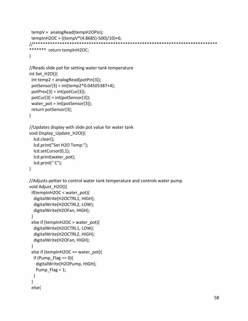
58
tempV = analogRead(tempH2OPin); tempInH2OC = ((tempV*(4.8685)-500)/10)+6; //*********************************************************************************** return tempInH2OC; } //Reads slide pot for setting water tank temperature int Set_H2O(){ int temp2 = analogRead(potPin[3]); potSensor[3] = int(temp2*0.04505387+4); potPrev[3] = int(potCur[3]); potCur[3] = int(potSensor[3]); water_pot = int(potSensor[3]); return potSensor[3]; } //Updates display with slide pot value for water tank void Display_Update_H2O(){ lcd.clear(); lcd.print("Set H2O Temp:"); lcd.setCursor(0,1); lcd.print(water_pot); lcd.print(" C"); } //Adjusts peltier to control water tank temperature and controls water pump void Adjust_H2O(){ if(tempInH2OC < water_pot){ digitalWrite(H2OCTRL1, HIGH); digitalWrite(H2OCTRL2, LOW); digitalWrite(H2OFan, HIGH); } else if (tempInH2OC > water_pot){ digitalWrite(H2OCTRL1, LOW); digitalWrite(H2OCTRL2, HIGH); digitalWrite(H2OFan, HIGH); } else if (tempInH2OC == water_pot){ if (Pump_Flag == 0){ digitalWrite(H2OPump, HIGH); Pump_Flag = 1; } } else{

59
digitalWrite(H2OCTRL1, LOW); digitalWrite(H2OCTRL2, LOW); digitalWrite(H2OFan, LOW); digitalWrite(H2OPump, LOW); } } //**************************** Humidity Functions ******************************// // Function for reading from humidity sensors int i2cRead2bytes(int deviceaddress, byte address) { // SET ADDRESS Wire.beginTransmission(deviceaddress); Wire.write(address); // address for sensitivity Wire.endTransmission(); // REQUEST RETURN VALUE Wire.requestFrom(deviceaddress, 2); // COLLECT RETURN VALUE int rv = 0; for (int c = 0; c < 2; c++ ) if (Wire.available()) rv = rv * 256 + Wire.read(); return rv; } //Read Humidity Sensors and Return Average float Get_Hum(){ if(count1 > 5){ digitalWrite(humSel, LOW); delay(200); if (FreqCount.available()) { unsigned long count = FreqCount.read(); RH0 = (offset-count)*sens/4096; } digitalWrite(humSel, HIGH); delay(200); if (FreqCount.available()) { unsigned long count1 = FreqCount.read(); RH1 = (offset-count1)*sens/4096; } RHAVG = ((RH0+RH1)/2)-4; return RHAVG; } } //Reads humidity value from slide pot

60
int Set_Hum(){ int hum = analogRead(potPin[1]); potSensor[1] = hum*0.0785 + 20; potPrev[1] = int(potCur[1]); potCur[1] = int(potSensor[1]); hum_pot = int(potSensor[1]); return potSensor[1]; } //Updates display with humidity value from slide pot void Display_Update_Hum(){ lcd.clear(); lcd.print("Set Humidity:"); lcd.setCursor(0,1); lcd.print(hum_pot); lcd.print("%"); } //Adjusts Humidity by turining on humidifier void Adjust_Hum(){ if(RHAVG < potSensor[1]){ digitalWrite(humCTRL, HIGH); } else {digitalWrite(humCTRL, LOW);} } //***************************** Blower Control *****************************// //Adjusts blower output depending on position of door void Adjust_Blower(){ int ReedVal = digitalRead(ReedSW); if(ReedVal == HIGH){ digitalWrite(blowCTRL, LOW); } else if(ReedVal == LOW){ digitalWrite(blowCTRL, HIGH); } else digitalWrite(blowCTRL, LOW); } //***************************** Display ******************************************// //Displays sensor values void Standard_Display(){ lcd.clear();

61
lcd.print("Temp:"); lcd.print(hoodTemp); lcd.print("C "); lcd.print("Hum:"); lcd.print(RHAVG); lcd.print("%"); lcd.setCursor(0,1); lcd.print("CO2:"); lcd.print(co2percent); lcd.print("%"); lcd.print("H2O:"); lcd.print(tempInH2OC); lcd.print("C"); } //***************************** Functions for MasterMind ********************// //Reads Sensor values and Slide pots void sensor_read(){ Get_Temp(); Get_Hum(); Get_CO2(); Get_H2O(); Set_Temp(); Set_Hum(); Set_CO2(); Set_H2O(); } //Checks if toggles have been flipped void check_toggles(){ int heatOnOff = digitalRead(heatTog); int humOnOff = digitalRead(humTog); int CO2OnOff = digitalRead(CO2Tog); int H2OOnOff = digitalRead(H2OTog); if(heatOnOff == LOW){ digitalWrite(heatLED, HIGH); Heat_Flag = 1; } else if(heatOnOff == HIGH) { digitalWrite(heatLED, LOW); digitalWrite(heaterCTRL, LOW); Heat_Flag = 0;

62
} if(humOnOff == LOW){ digitalWrite(humLED, HIGH); Hum_Flag = 1; } else if(humOnOff == HIGH){ digitalWrite(humLED, LOW); digitalWrite(humCTRL, LOW); Hum_Flag = 0; } if(CO2OnOff == LOW){ digitalWrite(CO2LED, HIGH); CO2_Flag = 1; } else if(CO2OnOff == HIGH){ digitalWrite(CO2LED, LOW); digitalWrite(CO2CTRL, LOW); CO2_Flag = 0; } if(H2OOnOff == LOW){ digitalWrite(H2OLED, HIGH); H2O_Flag = 1; } else if(H2OOnOff == HIGH){ digitalWrite(H2OLED, LOW); digitalWrite(H2OCTRL1, LOW); digitalWrite(H2OCTRL2, LOW); digitalWrite(H2OFan, LOW); digitalWrite(H2OPump, LOW); H2O_Flag = 0; Pump_Flag = 0; } } //Checks if slide pots have changed void check_pots(){ int i; for(i=0; i<4; i++){ if((potCur[i] != potPrev[i])) action[i] = 1; else action[i] = 0; } if(action[0] == 1){ Display_Update_Temp();

63
delay(100); } if(action[1] == 1){ Display_Update_Hum(); delay(100); } if(action[2] == 1){ Display_Update_CO2(); delay(100); } if(action[3] == 1){ Display_Update_H2O(); delay(100); } } //Updates actuators based on slide pot values and sensor values void update_actuators(){ //heater if(Heat_Flag == 1){ Adjust_Temp(); } //Humidity if(Hum_Flag == 1){ Adjust_Hum(); } //CO2 if(CO2_Flag == 1){ Adjust_CO2(); } //Water Pump if(H2O_Flag == 1){ Adjust_H2O(); } //Blower Adjust_Blower(); }