Embed Size (px)
Citation preview

LACE FLIGHT DYNAMICS EXPERIMENT
Shalom Fisher
Naval Research Laboratory
Washington, D. C.
Third NASA/DOD CSI Technology Conference
San Diego, California
January 29 - February 2, 1989
PRECEDING PAGE BLANK NOT FILMED 42"/
https://ntrs.nasa.gov/search.jsp?R=19900011770 2018-07-02T13:52:42+00:00Z

=
ABSTRACT
The Low Power Atmospheric Compensation Experiment (LACE) is scheduled
for launch in late 1989 into a 556 km altitude circular orbit of 430 inclination. The
LACE flight dynamics experiment, described in this report, is an experiment
secondary to the primary LACE mission. The purpose of the experiment is to provide
on-orbit systems identification of the LACE spacecraft. The structure of the LACE
spacecraft is of special interest to the CSI community. It incorporates 3
deployable/retractable booms of maximum length 45.72 m (150 ft) mounted on a
rectangular parallelepiped bus of mass 1,200 kg. The zenith directed gravity gradient
boom is mounted on the top of the bus; the retrore-fiect0rboom is mounted forward
and deployed along the velocity vector; the balance boom is mounted and pointed aft.
Attitude stabilization is accomplished by means of gravity gradient torques and by a
momentum wheel. The LACE flight dynamics experiment is designed to measure
modal frequencies, damping ratios, and oscillation amplitudes of the LACE
spacecraft, as well as the vibration intensity generated by boom deployments and
retractions. It is anticipated that this experiment will provide an opportunity for
improvements in the accuracy of computer simulations of flexible structures and
multibody dynamics.

DESIGN OF LACE FLIGHT DYNAMICS EXPERIMENT
The Low Power Atmospheric Compensation Experiment (LACE) is scheduled for
launch in late 1989 into a 556 km altitude circular orbit of 430 inclination, as illustrated in
figure 1. The LACE flight dynamics experiment, described in this report, is an experiment
secondary to the primary LACE mission. The purpose of the experiment is to provide on-orbit
systems identification of the LACE spacecraft. The structural configuration of the LACE
spacecraft is indicated in figure 1. Three deployable/retractable booms of maximum length
45.72 m (150 ft) are mounted on a rectangular parallelpiped bus of mass 1,200 kg. The
zenith directed gravity gradient boom has a tip mass of 90.7 kg and includes a magnetic
damper; the retroreflector boom and balance boom each have a tip mass of 15.9 kg. Attitude
stabilization is accomplished by the gravity gradient torques and by a momentum wheel.
The flight dynamics experiment hardware consists of 2 germanium corner cubes: one
proposed to be on the bus and the other on the balance boom. The FIREPOND laser radar
at the MIT Lincoln Laboratory will illuminate the cubes to measure the relative motion of the
boom with respect to the bus. Absolute bus rotation rates will be measured by means of the
on-board UltraViolet Plume Instrument (UVPI). Measurements will be made of vibration
frequencies, damping ratios, and oscillation amplitudes.
GRAVITY GRADIENT BOOM RETRO-REFLECTOR
& MAGNETIC DAMPER BOOM
BALANCE BOOM
LEADING RETRO-REFLECTOR
/i1 GERMANIUM
CORNER _
REFLECTOR 10.6 u., 800 WATTS REFERENCE LACE ORBIT
- 556km MAXIMUM ALTITUDE
- CIRCULAR
- INCLINATION 43 °
.w J
FIREPOND
BLOSSO.PO,NT
GROONDSrATIONLACE FLIGHT _
DYNAMICS EXPERIMENT "___ =
Figure 1 429

ISSUES ADDRESSED BY THE DYNAMICS EXPERIMENT
Structural modelling, environmental interactions, and boom deployment dynamics are
areas where the LACE flight dynamics experiment can provide useful data. At the present
time estimates of the vibration frequencies are based on static ground tests of the boom
structure. The flexural rigidity value obtained thereby ranges from 1.26 * 10 4 N_m2 (4.4 * 106
Ib-in 2 ) to 1.6 * 10 4 N_m 2 (5.5 "106 Ib-in2), giving an uncertainty in the vibration frequencies
of about 20%. Further uncertainties in the vibration frequencies, as well as in the gravity
gradient libration frequencies, aregenerated by twisting from differential day/night heating.
The amountof vibration damping is not well known. For example, in the SAFE experiment of
1984" a flexible,deployable "wing" of polymerfilm was attached to a boom similar
to the LACE booms. Damping rates were observed to be nonlinear (reference 1)with
most of the damping induced by the attached wing. In the case of LACE, with no boom
attachments, the experiment will measure the damping intri_nsic to the boom structures.
Furthermore, the flight dynamics experiment will provide a mechanism for evaluating
the influence of magnetic torques, gravity-gradient torques, and atmospheric drag on the
LACE structure. Also, vibrations generated by boom deployments and retractions such as
were observed in the SAFE experiment Wili be measurable by means of this experiment.
(Fig. 2.)
*Lockheed Missiles & Space Company, "Solar Array Flight Experiment: Final Report, "
LMSC-F087173, National Aeronautics and Space Administration, Marshall
Space Flight Center, Alabama, April 1986.
430

ISSUES ADDRESSED BY THE DYNAMICS EXPERIMENT
Accuracy of mathematical models and computer simulations
• Structural Models
Damping rates of vibration oscillations:
Oscillation frequencies:
Thermoelastic changes:
estimates .2 % to .5%
uncertainties of 20%
day/night changes in frequency
twisting from differential heating
Environmental interactions: atmospheric drag
gravity gradient torques
magnetic damping
Oscillations generated by boom deployments/retractions
Figure 2
431
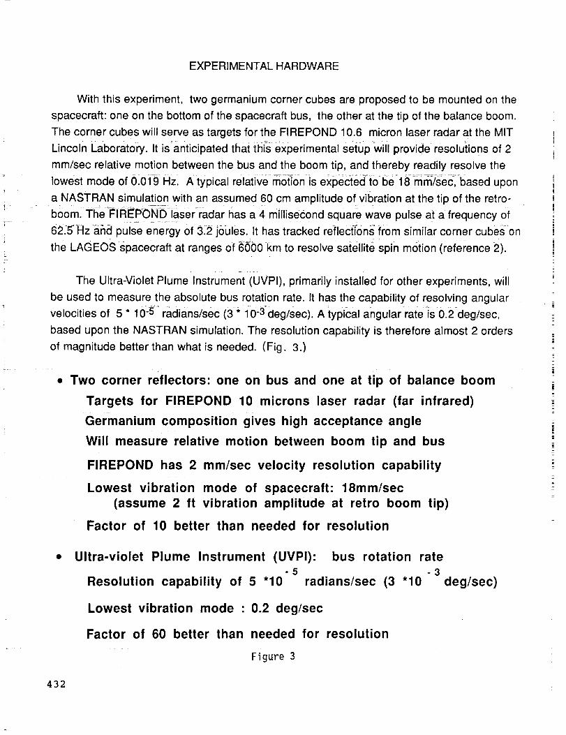
EXPERIMENTAL HARDWARE
With this experiment, two germanium corner cubes are proposed to be mounted on the
spacecraft: one on the bottom of the spacecraft bus, the other at the tip of the balance boom.
The corner cubes will serve as targets for the FIREPOND 10.6 micron laser radar at the MIT
Lincoln Laboratory. It is anticipated that this experimental setup will provide resoluiions of 2
mm/sec relative motion between the bus and the boom tip, and thereby readily resolve the
lowest mode of 01019 Hz, A typical relative m0t_on is expected _to be=l_mrn-/sec, based upon
a NASTRAN simulation with an assumed 60 cm amplitude of vibration at the tip of the retro-
boom. The_iR_POND laser_radar has a 4 millisecond square wave pulse at a frequency of
6215 Hz and pulse energy of 3.2 joules. It has tracked reflections from similar corner cubes on
the LAGEOS spacecraft at ranges of 6600 km to resolve satellite spin motion (reference 2).
The Ultra-Violet Plume Instrument (UVP1), primarily installed for other experiments, will
be used to measure the absolute bus rotation rate. It has the capability of resolving angular
velocities of 5* 10-5 _radians/sec (3* i0-3deg/sec). A typical angular rate_s0.2deg/sec,
based upon the NASTRAN simulation. The resolution capability is therefore almost 2 orders
of magnitude better than what is needed. (Fig. 3.)
Two corner reflectors: one on bus and one at tip of balance boom
Targets for FIREPOND 10 microns laser radar (far infrared)
Germanium composition gives high acceptance angle
Will measure relative motion between boom tip and bus
FIREPOND has 2 mm/sec velocity resolution capability
Lowest vibration mode of spacecraft: 18mm/sec
(assume 2 ft vibration amplitude at retro boom tip)
Factor of 10 better than needed for resolution
Ultra-violet Plume Instrument (UVPI)" bus rotation rate-5 -3
Resolution capability of 5 "10 radians/sec (3 "10 deg/sec)
Lowest vibration mode • 0.2 deg/sec
Factor of 60 better than needed for resolution
Figure 3
432
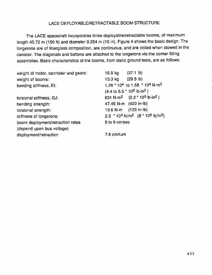
LACE DEPLOYABLE/RETRACTABLE BOOM STRUCTURE
The LACE spacecraft incorporates three deployable/retractable booms, of maximum
length 45.72 m (150 ft) and diameter 0.254 m (10 in). Figure 4 shows the basic design. The
longerons are of fiberglass composition, are continuous, and are coiled when stowed in the
canister. The diagonals and battens are attached to the Iongerons via the corner fitting
assemblies. Basic characteristics of the booms, from static ground tests, are as follows:
weight of motor, cannister and gears:
weight of booms:
bending stiffness, El:
torsional stiffness, GJ:
bending strength:
torsional strength:
stiffness of Iongerons:
boom deployment/retraction rates
(depend upon bus voltage)
deployment/retraction
16.8 kg (37.1 Ib)
13.3 kg (29.5 Ib)
1.26"104 tol.58 "104N-m 2
(4.4 to 5.5 * 106 Ib-in 2 )
631 N-m 2 (2.2 * 105 Ib-in 2 )
47.45 N-m (420 in-lb)
13.6 N-m (120 in-lb)
2.3 * 104 N/m 2 (8 * 106 Ib,/in2)
6 to 9 cm/sec
7.6 cm/turn
433

BASIC DESIGN
I 10-inch-DiameterSingle-laced Diagonal
Canister-nut Deployer(Mast diagonals not shown for clarity)
Elevating -.,,------nut region
Mast
storage
region
Turntable
region
'_ Ti_) Plate Assembly
Deployable Mast ComDonents
Batten
_ Diagonals (6 per bay)
Roller on pivot fitting
Longeron (3)
Deolo_ver ComDonents
Deployment guides
Deployer elevating nut
Deployment gear
Cylindrical canister
Turnlable ring
Base plate
Mechanical stops
Figure 4
434

COORDINATE SYSTEM OF LACE ANALYSIS
Figure 5 shows the spacecraft oriented coordinate system used for the structural
analysis and environmental modelling of the LACE experiment. The yaw or "z" axis is
directed toward the zenith, with the pitch or "x" axis directed toward the negative orbit
normal, and the roll or "y" axis is perpendicular to the other two to form a right-handed
coordinate system. With LACE in a circular orbit, the roll axis is along the velocity vector.
Z
ORBITAL
ANGULARRATE
/
x
SPACECRAFTVELOCITY
E,'_RTH
Figure 5
435
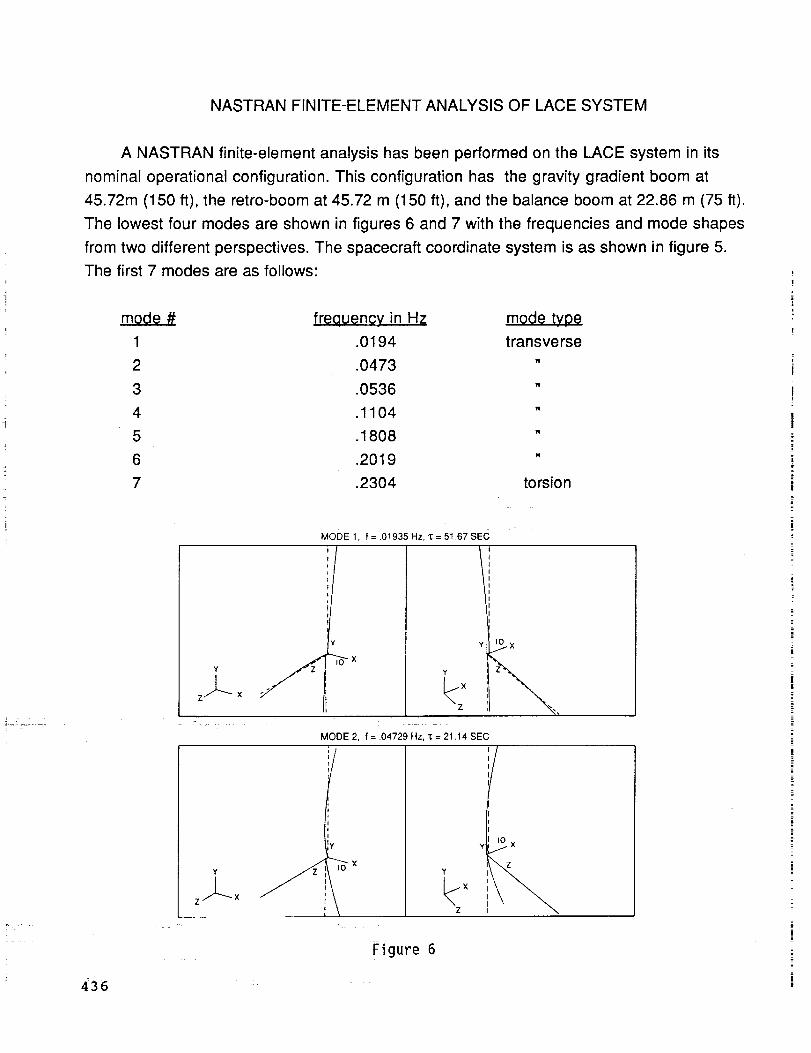
NASTRAN FINITE-ELEMENT ANALYSIS OF LACE SYSTEM
A NASTRAN finite-element analysis has been performed on the LACE system in its
nominal operational configuration. This configuration has the gravity gradient boom at
45.72m (150 ft), the retro-boom at 45.72 m (150 ft), and the balance boom at 22.86 m (75 ft).
The lowest four modes are shown in figures 6 and 7 with the frequencies and mode shapes
from two different perspectives. The spacecraft coordinate system is as shown in figure 5.
The first 7 modes are as follows:
mode # freauenoy in Hz mode ty0e
1 .0194 transverse
2 .0473 "
3 .0536 "
4 .1104 "
5 .1808 "
6 .2019 "
7 .2304 torsion
z...L- x
=
MODE 1, f = .01935 Hz, "_= 51_67 SEC
Y_.x
I •
MODE 2, f = .04729 Hz, '_= 21.14 SEC
/
I0 ×Y /
× :z I
Figure 6
436
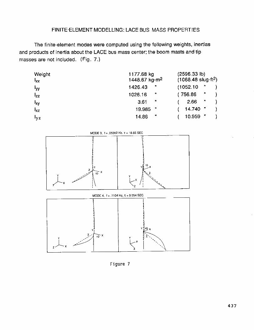
FINITE-ELEMENT MODELLING: LACE BUS MASS PROPERTIES
The finite-element modes were computed using the following weights, inertias
and products of inertia about the LACE bus mass center; the boom masts and tip
masses are not included. (Fig. 7.)
Weight
Ixx
lyy
Izz
Ixy
Ixz
lyz
1177.68 kg1448.67 kg-m2
1426.43 " (1052.10 " )
1026.16 " ( 756.86 " )
3.61 " ( 2.66 " )
19.985 " ( 14.740 " )
14.86 " ( 10.959 " )
(2596.33 Ib)
(1068.48 slug-ft 2)
Y
J--xZ
MODE 3, f = .05362 Hz, "_ = t8.65 SE(
Y
\xi
I0 X/
MODE 4, f = .1104 Hz, "_ = 9.054 SEC
Y
Z
Figure 7
437
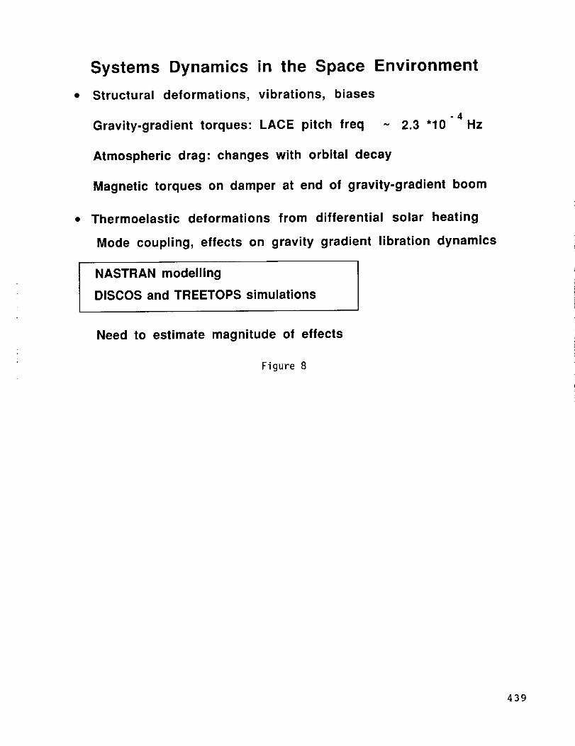
FLEXIBLE SYSTEM DYNAMICS IN THE SPACE ENVIRONMENT
The flexibility of the LACE spacecraft complicates the dynamical interaction of the
system with the space environment even though the system modal frequencies, with the
lowest mode of .019 Hz, are widely separated from the gravity gradient pitch libration
frequency of 2.3 * 10 -4 Hz. One complication, for example, is that elastic deformations from
environmental stresses can generate 2nd order changes in the system inertial properties
and thereby modify the biases in roll, pitch and yaw that apply to rigid-body spacecraft.
Another complication is mode coupling generated by thermoelastic deformations. The
environmental stresses include components that are time dependent functions of orbital
motion and spacecraft orientation, as well as components that are more steady-state such as
atmospheric drag.
The estimation of the magnitude of these effects is part of the LACE flight dynamics
experiment. Thestudy is proceeding by means of the DISCOS and TREETOPS simulation
programs (reference 3"*), using system vibration modal data obtained from a NASTRAN
finite-element program. A 3 -D model of the boom structure has been developed with
NASTRAN, to estimate the thermoelastic distortions generated by solar heating. : (Fig. 8.)
**TREETOPS is a simulation program written by R.P. Singh and R. J_ Vandervoort of
Dynacs Engineering Co., Inc., Clearwater, Florida, under contract to Marshall Space
Flight Center, Huntsville, Aiabama.
438
Systems Dynamics in the Space Environment
• Structural deformations, vibrations, biases
-4HzGravity-gradient torques: LACE pitch freq ~ 2.3 "10
Atmospheric drag: changes with orbital decay
Magnetic torques on damper at end of gravity-gradient boom
• Thermoelastic deformations from differential solar heating
Mode coupling, effects on gravity gradient libration dynamics
NASTRAN modelling
DISCOS and TREETOPS simulations
Need to estimate magnitude of effects
Figure 8
439

EXPERIMENT DESIGN OVERVIEW
The experiment includes the modelling of the LACE SYstem with NASTRAN and the
multi-body simulation programs DISCOS and TREETOPS, together with environmental
models of the atmospheric drag (reference 4), magnetic damping, and solar heating. An
analysis of the on-orbit measurements requires a good estimate of system outputs through
numerical simulation. Feedback between the measurements and predicted values enables
upgrades of structural parameter estimations and environmental assumptions to improve the
computer modeliing. (Fig. 9.)
boom dynamics models--- NASTRAN
multibody systems dynamics -- DISCOS, TREETOPS
environmental models -- atm model, solar, magnetic
boom deployment/retraction dynamics
! LACE spacecraft modelling I
Ion-orbit experiment and measurements
v
,LTime and frequency domain analysis
Predicted performance from
I Differences between
1 Upgrade system models I
models
models and measurements
Figure 9
440
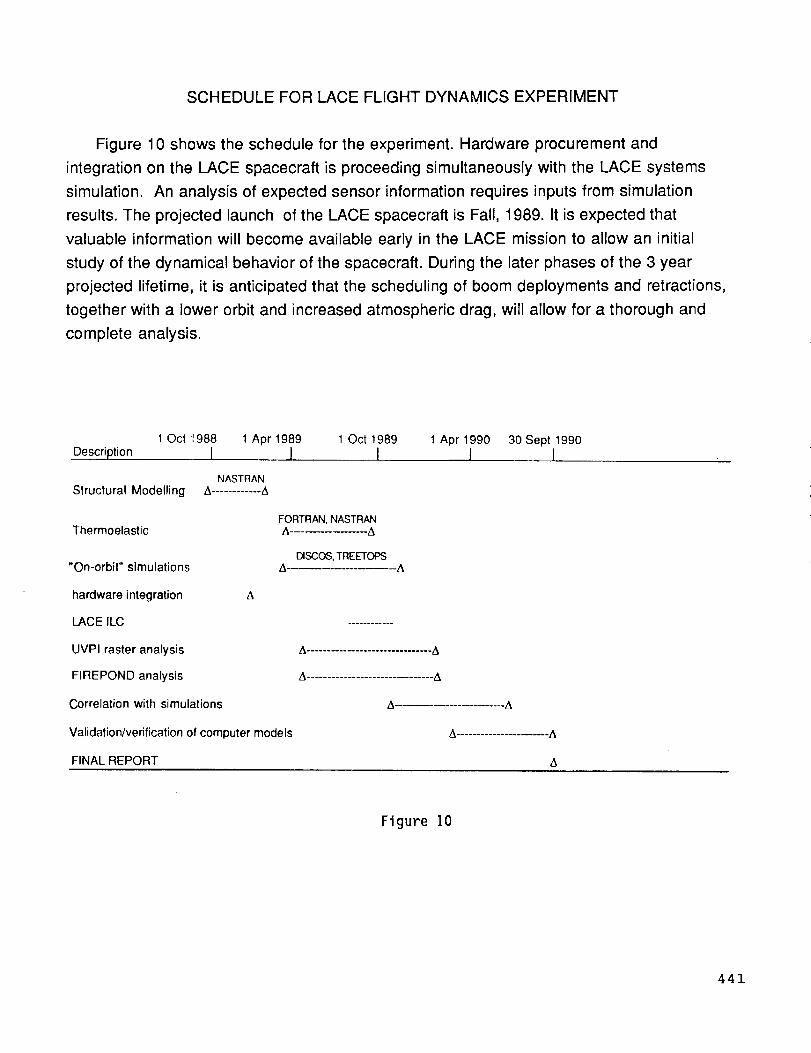
SCHEDULE FOR LACE FLIGHT DYNAMICS EXPERIMENT
Figure 10 shows the schedule for the experiment. Hardware procurement and
integration on the LACE spacecraft is proceeding simultaneously with the LACE systems
simulation. An analysis of expected sensor information requires inputs from simulation
results. The projected launch of the LACE spacecraft is Fall, 1989. It is expected that
valuable information will become available early in the LACE mission to allow an initial
study of the dynamical behavior of the spacecraft. During the later phases of the 3 year
projected lifetime, it is anticipated that the scheduling of boom deployments and retractions,
together with a lower orbit and increased atmospheric drag, will allow for a thorough and
complete analysis.
1 Oct _ 988 1 Apr t 989 1 Oct 1989 1 Apr 1990 30 Sept 1990
Description { { { { {
NASTRANStructural Modelling A ............ A
FORTRAN, NASTRANThermoelastic A ................ A
DISCOS,TREETOPS"On-orbit" simulations A.................... A
hardware integration A
LACE ILC ...........
UVPI raster analysis A............................... A
FIREPOND analysis A.............................. A
Correlation with simulations A ................... A
Validation/verification of computer models A .................... A
FINAL REPORT A
Figure 10
441

ACKNOWLEDGEMENTS
The author would like to thank J. Schaub and W. Adkins of the Spacecraft Engineering
Department, NRL, for their assistance and cooperation in implementing the last-minute
engineering modifications to LACE required by this experiment. D. Penn and D. Horan of
the LACE spacecraft team have also been very helpful. He would also like to thank R.
McClelland, an NRL contractor, for his assistance in design of the engineering modifications,
and R. J. Dornsife of the US Army Corps of Engineers for assistance in the NASTRAN
analysis. The autl_or's supervisor, M. Brownl has been very supportive during the many
phases of the development of this experiment. The experimental design was worked out by
a committee composed of W. Keith Belvin of NASA, Langley, R. Sasiela of MIT Lincoln
Laboratory, W.G. Stevenson and J. I. Perkins of Science Applications International
Corporation, and Dr. G.K. Man of JPL. Useful discussions on the application of the
FIREPOND lasar radar have been held with L. Sullivan and R.E. Knowlden of MIT Lincoln
Laboratory.
442

REFERENCES
° Leighton E. Young & Homer C. Pack, Jr.,"Solar Array Flight Experiment/Dynamic
Augmentation Experiment," NASA Technical Paper 2690, National Aeronautics and
Space Administration, Marshall Space Flight Center, Alabama, February 1987.
2. Steven C. Cohen and David E. Smith, "LAGEOS Scientific Results: Introduction," Journal
of Geophysical Research, Vot. 90, No. B11, pages 9217-9220, September 30, 1985.
, Bodley, C.S., Devers, A.D., Park, A.C., Frisch, H.P., "A Digital Computer Program for the
Dynamic Interaction Simulation of Controls and Structure (DISCOS)," NASA Technical
Paper # 1219, National Aeronautics and Space Administration, Goddard Space Flight
Center, Greenbelt, Maryland, May, 1978.
. Jacchia, L. G., "New Static Models of the Thermosphere and Exosphere with Empirical
Temperature Profiles," SAO Special Report # 313, Smithsonian Institution, Astrophysical
Observatory, Cambridge, Massachusetts, May, 1970.
Jacchia, L.G., "Static Diffusion Models of the Upper Atmosphere with Empirical
Temperature Profiles, " Smithsonian Contr. Astrophys., Vol. 8, No. 9, pp 215-257, 1965.
443

Ii
iI
q
i
1_
|
Zn
|
m
!=
z
i|.m