Embed Size (px)
Citation preview
LLaabbVVIIEEWW VVII LLiibbrraarryy ffoorr tthhee
CCoommppuummoottoorr 66KK MMoottiioonn CCoonnttrroolllleerr
VIEWPOINT SYSTEMS, INC. 800 West Metro Park, Rochester, NY 14623
November 2002 Edition Part Number VS-6K02

Important Information
Viewpoint Systems, Inc. does not warrant that the Program will meet Customer's requirements or will operate in the combinations which may be selected by the Customer or that the operation of the Program will be uninterrupted or error free or that all Program defects will be corrected.
VIEWPOINT SYSTEMS, INC. DOES NOT AND CANNOT WARRANT THE PERFORMANCE OR RESULTS THAT MAY BE OBTAINED BY USING THIS SOFTWARE. ACCORDINGLY, THE SOFTWARE AND ITS DOCUMENTATION ARE SOLD "AS IS" WITHOUT WARRANTY AS TO THEIR PERFORMANCE, MERCHANTABILITY, OR FITNESS FOR ANY PARTICULAR PURPOSE. THE ENTIRE RISK AS TO THE RESULTS AND PERFORMANCE OF THE PROGRAM IS ASSUMED BY YOU.
NEITHER VIEWPOINT SYSTEMS, INC. NOR ANYONE ELSE WHO HAS BEEN INVOLVED IN THE CREATION, PRODUCTION, OR DELIVERY OF THIS SOFTWARE SHALL BE LIABLE FOR ANY DIRECT, INCIDENTAL, OR CONSEQUENTIAL DAMAGES, SUCH AS, BUT NOT LIMITED TO, LOSS OF ANTICIPATED PROFITS OR BENEFITS, RESULTING FROM THE USE OF THE PROGRAM OR ARISING OUT OF ANY BREACH OF ANY WARRANTY. SOME STATES DO NOT ALLOW THE EXCLUSION OR LIMITATION OF DIRECT INCIDENTAL OR CONSEQUENTIAL DAMAGES, FOR THE ABOVE MAY NOT APPLY TO YOU.
LabVIEW is a registered trademark of National Instruments Corporation
Compumotor and 6K are registered trademarks of Parker-Compumotor, Inc.
All other brand and product names are trademarks or registered trademarks of their respective companies.
Copyright © 2002, Viewpoint Systems, Inc.
All Rights Reserved.
Reproduction or adaptation of any part of this documentation beyond that permitted by Section 117 of the 1976 United States Copyright Act without permission of the Copyright owner is unlawful.
Printed in the U.S.A.

Contents
1 Introduction................................................................................................................. 1 2 System Requirements.................................................................................................. 1 3 Contents of the Viewpoint 6K VI Motion Library ..................................................... 2 4 Recommendations for Using the 6K VI Motion Library............................................ 3
4.1 Communication Methods .................................................................................... 3 4.2 Programming Strategy ........................................................................................ 3
5 Requirements for Using the 6K VI Motion Library ................................................... 4 5.1 Motion Planner Communication......................................................................... 4 5.2 Motion Planner Program File.............................................................................. 4 5.3 Motion Planner Control ...................................................................................... 4
6 6K VI Motion Library Software Installation .............................................................. 5 7 Communication Setup ................................................................................................. 5
7.1 Hardware Setup ................................................................................................... 6 7.2 NTFEN1 vs. NTFEN2 ........................................................................................ 6 7.3 The ARP –S Static Mapping Procedure.............................................................. 7 7.4 Enable Ethernet Communication........................................................................ 9 7.5 If Ethernet is not Connected................................................................................ 9
8 Automating the ARP Command ................................................................................. 9 8.1 Creating an ARP.BAT File ................................................................................. 9 8.2 DHCP Ethernet Connections ............................................................................ 10 8.3 Multiple 6K Controllers and ARP.BAT ........................................................... 10
9 Creating an INI File .................................................................................................. 11 9.1 INI File Parameters ........................................................................................... 11 9.2 Using the INI File ............................................................................................. 12 9.3 Running the Examples ...................................................................................... 13
10 Using the 6K Library ............................................................................................ 15 10.1 Calling a 6K Program from LabVIEW ............................................................. 15 10.2 Motion Scaling in the 6K vs. LabVIEW........................................................... 16
11 Viewpoint 6K VI Motion Library RS-232 VIs ..................................................... 17 12 LabVIEW 6K VI Reference.................................................................................. 18
12.1 Interface Engine VI Reference.......................................................................... 18 12.2 Function VI Reference ...................................................................................... 30
13 How To Contact Us …………………………………………………………….56

1
1 Introduction The Viewpoint 6K VI Motion Library is a set of LabVIEW VIs that provide an interface to Compumotor’s 6K line of motion controllers. A complete motion application can be implemented in LabVIEW by using the Viewpoint 6K VI Motion Library and Motion Planner, a software program provided with the Compumotor 6K product. For more information about Motion Planner and the Compumotor 6K product, refer to the following Compumotor publications shipped with your 6K controller:
• 6K Series Command Language Reference Manual • 6K Series Hardware Installation Guide • 6K Series Programmer’s Guide
These documents are also available in portable document format on the Compumotor website.
2 System Requirements The following items are required in order to use the Viewpoint 6K VI Motion Library:
• IBM-compatible computer running Windows XP, 2000, NT, or 98/95 with 64 MB RAM minimum and 12 MB available hard drive space
• LabVIEW 6.02 or greater installed on your computer • Motion Planner 4.1 or greater installed on your computer • A 6K program (.prg) file, built using Motion Planner, that configures the 6K
communication and motion parameters that are specific to your system • Either an RS-232 cable and working RS-232 communications with your 6K
controller or • Ethernet LAN card installed and properly configured in your computer and an
Ethernet crossover cable or hub connected from the computer to the 6K controller
Part 1 – Essential Information
2
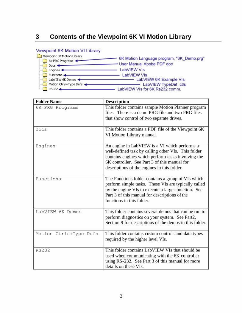
3 Contents of the Viewpoint 6K VI Motion Library
Folder Name Description 6K PRG Programs This folder contains sample Motion Planner program
files. There is a demo PRG file and two PRG files that show control of two separate drives.
Docs This folder contains a PDF file of the Viewpoint 6K VI Motion Library manual.
Engines An engine in LabVIEW is a VI which performs a well-defined task by calling other VIs. This folder contains engines which perform tasks involving the 6K controller. See Part 3 of this manual for descriptions of the engines in this folder.
Functions The Functions folder contains a group of VIs which perform simple tasks. These VIs are typically called by the engine VIs to execute a larger function. See Part 3 of this manual for descriptions of the functions in this folder.
LabVIEW 6K Demos This folder contains several demos that can be run to perform diagnostics on your system. See Part2, Section 9 for descriptions of the demos in this folder.
Motion Ctrls+Type Defs This folder contains custom controls and data types required by the higher level VIs.
RS232 This folder contains LabVIEW VIs that should be used when communicating with the 6K controller using RS-232. See Part 3 of this manual for more details on these VIs.

3
4 Recommendations for Using the 6K VI Motion Library
4.1 Communication Methods The Viewpoint 6K VI Motion Library is built upon Compumotor’s Active X executable Com6srvr.exe, which is installed with Compumotor’s Motion Planner. The Com6srvr.exe is an automation server and contains three Active X objects: Com6srvr.INet for ethernet, Com6srvr.IRs232 for RS232 and Com6srvr.Igemini for Gemini GGV drivers. Note that the Viewpoint 6K VI Motion Library does not support the Com6srvr.Igemini object. The VIs included with the Viewpoint 6K VI Motion Library have been designed to use the Com6srvr.INet ActiveX server for ethernet communications. Some low level VIs that can utilize the Com6srvr.IRs232 ActiveX server, which has very limited methods and properties, have also been included. Viewpoint strongly recommends an ethernet connection for communication between the computer and the 6K controller to take full advantage of the Viewpoint Systems 6K VI Motion Library.
4.2 Programming Strategy To make the best use of the 6K controller with LabVIEW, we recommend a strategy of writing motion programs with the 6K motion language, and allowing LabVIEW to interact with these programs. This strategy allows you to compartmentalize motion, tooling control, tooling protection and safety in the 6K motion language while LabVIEW performs data acquisition, supervisory control, man machine interface, etc. LabVIEW can also control motion in the 6K controller, but this is not recommended.

4
5 Requirements for Using the 6K VI Motion Library Note: If you do not succeed with the tasks described in this section, do NOT expect to be successful using LabVIEW to integrate the 6K Motion Controller into your LabVIEW application.
5.1 Motion Planner Communication To be successful with LabVIEW programming for the 6K controller, you must first be able to communicate with your 6K controller using Motion Planner via RS-232 or ethernet. Your LabVIEW VIs will not work if you cannot communicate with your 6K controller using Motion Planner. Refer to Part 2 of this manual for instructions on setting up communication with your 6K controller.
5.2 Motion Planner Program File You must build and save (using Motion Planner) a Compumotor 6K programming language .prg file that properly configures your specific motion control system. The 6K .prg file is where you define parameters such as:
• The number of axes in your system • Which axes are servo motors and which are stepper motors • The resolution of your encoders or steps per revolution • Pulses or steps per measurement unit (i.e . revolutions, millimeters, inches,
etc.) • I/O configuration
Note: Viewpoint has included a 6K example .prg file named 6K_Demo.prg that is located in Program Files\Viewpoint 6K Motion Library\6K PRG Programs. There are also many 6K example programs available at Compumotor’s website.
5.3 Motion Planner Control You must be able to control and exercise your motion hardware using Motion Planner. You should be able to debug and test your system using Motion Planner to verify that you can move your motors, check velocities, accelerations, decelerations, homing, over travel limits, inputs and outputs. In summary, you need to verify that your system works correctly using Motion Planner before you begin writing code for your application in LabVIEW.
5
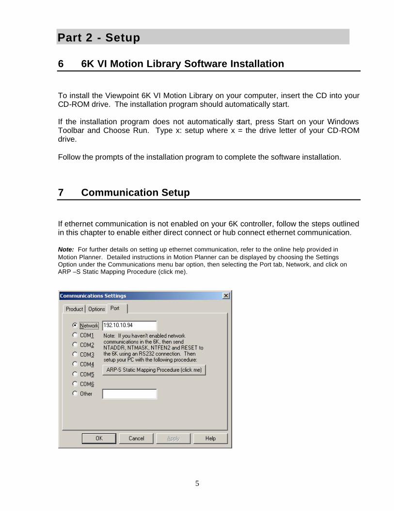
6 6K VI Motion Library Software Installation To install the Viewpoint 6K VI Motion Library on your computer, insert the CD into your CD-ROM drive. The installation program should automatically start. If the installation program does not automatically start, press Start on your Windows Toolbar and Choose Run. Type x: setup where x = the drive letter of your CD-ROM drive. Follow the prompts of the installation program to complete the software installation.
7 Communication Setup If ethernet communication is not enabled on your 6K controller, follow the steps outlined in this chapter to enable either direct connect or hub connect ethernet communication. Note: For further details on setting up ethernet communication, refer to the online help provided in Motion Planner. Detailed instructions in Motion Planner can be displayed by choosing the Settings Option under the Communications menu bar option, then selecting the Port tab, Network, and click on ARP –S Static Mapping Procedure (click me).
Part 2 - Setup

6
7.1 Hardware Setup To set up ethernet communication with your 6K controller, you will need ethernet cable(s) appropriate for your type of communication. If you are connecting the 6K controller directly to the computer, you need to use an ethernet cross-over cable. If your 6K controller is connected to a network and/or a hub, you need to use standard ethernet patch cables to connect the 6K controller and computer to the network/hub. If you are connecting your 6K controller to a network that is accessible to others in your office, you will need to work with your I.T. department or System Administrator to have an IP address assigned to your 6K controller. Refer to the help section in Motion Planner for details on how to change the IP address of the 6K controller. To properly configure ethernet communication, RS-232 communication must first be established. Connect a RS-232 cable between the RS-232 interface on the 6K controller and one of the serial ports on your computer. In Motion Planner, select Communications - Settings – Port and then select the COM port you used to connect to the 6K controller. Select OK. If serial communication is properly set up, typing TNT in the Terminal Window will display status information. If no information is seen, check your RS-232 cable and connections.
7.2 NTFEN1 vs. NTFEN2 To enable or disable ethernet communication, a NTFEN command needs to be specified in the Terminal Window of Motion Planner. This command is also used in the .PRG file which configures your system. NTFEN0 : Use NTFEN0 to disable ethernet communication. NTFEN1 : NTFEN1 is useful if you are using Windows 95/98 with no file sharing and a closed network. NTFEN2 : NTFEN2 is recommended as the standard ethernet communication mode, even if you are using a closed network and no file sharing. NTFEN2 is especially useful if you are using Windows NT, 2000, XP (or /2000/XP) or Windows 95/98 with file sharing and/or an open network. Note: When using NTFEN2, you must also follow the ARP -S Static Mapping procedure. This is described in the next section. Note: When using COM1, you can communicate to the 6K over either the ethernet port or the COM1 port at one time. In other words, you cannot communicate via ethernet and RS -232 using

7
COM1 at the same time. All other COM ports can communicate simultaneously with the ethernet port. If you have not already done so, type NETFENZ in the Terminal Window. In summary, if you must expose your 6K to a corporate network, use NTFEN2 with ARPing. If you are going to connect your 6K(s) to just one computer, then use NTFEN1 without ARPing.
7.3 The ARP –S Static Mapping Procedure
Type TNT in the Motion Planner Terminal Window. Several pieces of information are displayed, including
• The 6K IP Address • The 6K ethernet address in hex (known as the MAC address)
Obtaining the Computer’s IP Address Now, go to a MS-DOS prompt by using the Start-Programs menu. Depending on your operating system, the MS-DOS prompt is either in the list of programs or under Accessories. MS-DOS prompt may also be referred to as Command Prompt. For users of Windows 98/NT/2000/XP, type IPCONFIG. The IP address of the computer is displayed.
8
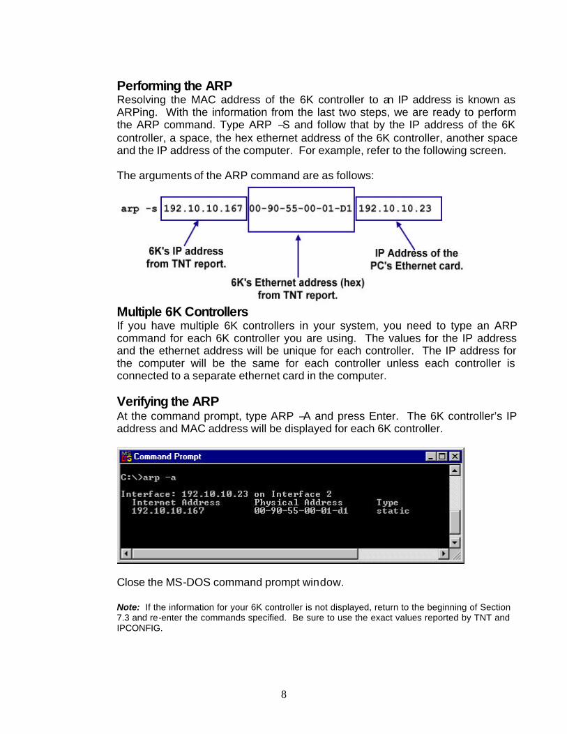
Performing the ARP Resolving the MAC address of the 6K controller to an IP address is known as ARPing. With the information from the last two steps, we are ready to perform the ARP command. Type ARP –S and follow that by the IP address of the 6K controller, a space, the hex ethernet address of the 6K controller, another space and the IP address of the computer. For example, refer to the following screen.
The arguments of the ARP command are as follows:
Multiple 6K Controllers If you have multiple 6K controllers in your system, you need to type an ARP command for each 6K controller you are using. The values for the IP address and the ethernet address will be unique for each controller. The IP address for the computer will be the same for each controller unless each controller is connected to a separate ethernet card in the computer. Verifying the ARP At the command prompt, type ARP –A and press Enter. The 6K controller’s IP address and MAC address will be displayed for each 6K controller.
Close the MS-DOS command prompt window. Note: If the information for your 6K controller is not displayed, return to the beginning of Section 7.3 and re-enter the commands specified. Be sure to use the exact values reported by TNT and IPCONFIG.

9
7.4 Enable Ethernet Communication
From the terminal window in Motion Planner, choose Communications – Settings from the menu. Select the Port tab and click on Network. In the space following Network, enter the IP address of your 6K controller and Select OK. From the Terminal window, type TNT and press Enter. The status displayed should indicate that ethernet is connected.
7.5 If Ethernet is not Connected If TNT does not report “Ethernet Connected”, power down your 6K controller, re-power the 6K controller, and repeat the instructions in Sections 7.2, 7.3 and 7.4.
8 Automating the ARP Command
8.1 Creating an ARP.BAT File
Creating an ARP.BAT file allows your computer to automatically resolve the 6K controller’s MAC address with an IP address when it is booted. Otherwise, you will have to manually perform this procedure every time you boot your computer. If you use NTFEN2 you will need to use an ARP.BAT file to statically map the IP address of the computer to the 6K controller. You will need the MAC address of the 6K controller to use an ARP.BAT file. Using NTFEN2 with a statically mapped ARP will provide some level of security on a network to prevent others on the network from connecting to your 6K controller(s). If you use NTFEN1, you only need to know the IP address of the 6K controller. It is not necessary to create an ARP.BAT file or know the MAC address of the 6K controller. For a Windows 95/98 computer, add the ARP -S command to the autoexec.bat file. For a Windows NT/2000/XP computer, create a batch file that contains the ARP –s command. Save the file as “6KARP.BAT” to the root directory of the C drive. The following is a sample 6K ARP.BAT file:

10
Using Windows Explorer, create a shortcut to this file and then cut and paste the shortcut into the Startup folder. Alternatively, you can run it programmatically from LabVIEW during the connection phase of startup to the 6K controller. Note: After setting the IP address settings and creating the 6K ARP.BAT file, power down the 6K controller and power it up again, then run the 6Karp.bat for all of the new settings to take effect.
8.2 DHCP Ethernet Connections
If your computer connects to the network using DHCP, where the Server automatically assigns an IP address to your computer, do not include the IP address for your computer in the ARP.BAT file. Thus, your ARP command should have the following format:
8.3 Multiple 6K Controllers and ARP.BAT
If you have multiple 6K controllers, each controller needs to have a separate line in the ARP.BAT file as described in Section 7.3. The following is an example of a multiple 6K ARP.BAT file for a statically mapped system:
The following is an example of a multiple 6K ARP.BAT file for DHCP system.

11
9 Creating an INI File
Viewpoint’s 6K VI Motion Library uses an INI file to pass information about the system configuration to the LabVIEW VIs. The 6Kx Comm Launcher.vi uses the INI file specified to set up communications, set parameters, and initialize the hardware to a known state.
9.1 INI File Parameters The INI File contains information for several parameters needed to execute 6K VIs. The parameters specified in the INI File are as follows: INI Parameter Description 6K_Program1= This parameter specifies the path and filename of the 6K .prg
file that is downloaded to and runs on the 6K controller. This program is created in Compumotor’s Motion Planner by the user or for the user. The 1 refers to the first 6K controller on the network. A second 6K controller would use the parameter 6K_Program2 and so on.
6K_Setup1= This parameter specifies the name of the 6K program label that is used to configure, setup or initialize the motion system. The 1 refers to the first 6K controller on the network. A second 6K controller would use the parameter 6K_Setup2 and so on.
6K_Addr1= This parameter specifies three settings that are separated by commas. The three parameters are as follows:
• IP address of the 6K ethernet connection • Number of axes on this 6K controller • Fast Status update rate in milliseconds.
The 1 refers to the first 6K controller on the network. A second 6K controller would use the parameter 6K – Addr2 = and so on.
Note: The fastest Fast Status update rate that can be set is 10 milliseconds.

12
6K_ARP= This parameter sets the path and filename of the ARP batch
file.
6K_Boxes= This parameter specifies the number of 6K controllers that are connected via ethernet in your system.
9.2 Using the INI File
An INI file called 6Kx.Config.INI is provided. This file is located with the demos in the LabVIEW 6K Demos Folder. For the demos to run properly, the 6Kx.Config.INI file needs to reside in the same folder as the demo VIs. In general, the INI file can be located wherever it is convenient, but the LabVIEW VIs will need to reflect the path of the file. A sample single 6K controller INI file follows:
[6K_Motion] 6K_Program1="/C/ Viewpoint 6K Motion Library/6K PRG Programs/6K_Demo.prg" 6K_Setup1=SETUP 6K_Addr1=192.10.10.65,4,20 6K_ARP="/C/ Viewpoint 6K Motion Library/ LabVIEW 6K Demos/6K_arp.bat" 6K_Boxes=1 The INI file can support multiple 6K controllers connected to a LAN. A sample multiple 6K controller INI file follows: [6K_Motion] 6K_Program1="/C/ Viewpoint 6K Motion Library/6K PRG Programs/6K_Multi1.prg" 6K_Addr1=192.10.10.65,4,10 6K_Setup1=SETUP 6K_Program2=”/C/Viewpoint 6K Motion Library/6K PRG Programs/6K_Multi2.prg” 6K_Addr2=192.10.10.62,4,10 6K_Setup2=SETUP 6K_ARP="/C/ Viewpoint 6K Motion Library/ LabVIEW 6K Demos/6KMulti_arp.bat" 6K_Boxes=2 To see how to interface to the INI file in LabVIEW, refer to the following LabVIEW code:

13
9.3 Running the Examples
The following flow chart shows how to proceed in order to run the supplied examples:
Please open, examine and run some of the LabVIEW 6K demo-example VIs.\\Viewpoint 6K Motion Library\LabVIEW 6K Demos\
Configure your 6K systemcommunications and
motion parameters usingMotion Planner.
Create your 6K .prg file.
Exercise your 6K motionsystem and verify allworks properly using
Motion Planner.
START HEREMotion systemworks properly
?
NO
YES
6K Direct Commands Example.viThis is the simplest of the examples. This VI
formats 6K command strings and transmits them tothe 6K.
6K Test Functions Example.viThis VI demonstrates some of the VIs that are used
to write commands, read & to write variables andget status.
6K Simple Move Example.viThis VI demonstrates how to use some of the VIs
that are used to specify and command motion.
6K Read-Write to any Variable Example.viThis VI demonstrates how to use some of the VIs
that perform reads & writes to 6K variables.
6K Diagnostic Example.viThis is the highest level or most complex of the
example VIs. This example is used to demonstratemost of the functionality of the Viewpoint 6K Motion
VI library.

14
Special considerations for 6K Extended I/O EVM 32 SIMMS: If you are using Compumotor 6K extended I/O you will want to run our demo example VI named “6K Test Extended I/O Example.vi”. There are sub VIs that perform the read and write functions for both extended digital and analog I/O. Note: Our example is configured for extended I/O that is plugged into an EVM32 in the following configuration: SIMM slot #1, channels 1-8 = 8 digital inputs. SIMM slot #2, channels 9-16 = 8 digital outputs. SIMM slot #3, channels 17-24 = 8 analog inputs. SIMM slot #4, channels 25-32 = 8 analog outputs. Your configuration and addressing will probably be different.

15
10 Using the 6K Library
10.1 Calling a 6K Program from LabVIEW The VIs included in the Viewpoint 6K VI Motion Library provide connectivity and the most commonly used functions for the Compumotor 6K motion controller. This includes:
• Set distance • Set acceleration • Set velocity • Read and write program variables • Perform move • Perform homing • Control I/O • Monitor limits and I/O • Monitor positions
To make the best use of the 6K controller with LabVIEW, we recommend a strategy of writing motion programs with the 6K motion language, and allowing LabVIEW to interact with these programs. This strategy allows you to compartmentalize motion, tooling control, tooling protection and safety in the 6K controller while the computer and LabVIEW perform data acquisition, supervisory control, man machine interface, etc. An example 6K language demo program called “6K_Demo.prg” is included in the following folder: \Viewpoint 6K Motion Library\6K PRG Programs\ In the upper right of this demo screen, there are three 6K motion program labels that you can call. This demonstrates how to call 6K labels from LabVIEW. Selecting any of the three function rows (Custom Homing, Set Recipe Variables, or Move 1 Then Move 2) and clicking on [Execute] will cause a binary bit (VARBZ bit 1, 2, or 3) to turn on for two seconds. These three function calls execute the 6K program labels CHOMEG, WRRECP and ONETWO, respectively. See this example in LabVIEW for more details on accessing the 6K program from LabVIEW.
Part 3 – Programming

16
10.2 Motion Scaling in the 6K vs. LabVIEW
Typically, motion scaling is specified in the 6K motion program. The 6K controller has motion language commands for configuring motion scaling such as: SCLD – Distance Scaling SCLV – Velocity Scaling SCLA – Acceleration Scaling SCALE – Scaling enable/disable Motion Scaling can also be done in LabVIEW. For example, assume a 4 axis system that has 4 servo motors with encoder feedback of 1000 counts/revolution pre-quadrature and 4000 counts/revolution post-quadrature. Axes 1,2 and 3 are linear axis stages with a pitch of 10 millimeters/revolution. Axis 4 is a rotary axis that rotates 300 millimeters/revolution (roller has a 300 mm circumference). To specify distance in millimeters, we need to know that
4000 counts rev 10 mm/rev for axes 1, 2, and 3 and
4000 counts/rev 300 mm/rev
for axis 4. To scale in LabVIEW, set up the following in Motion Planner: SCALE1 ;Enable Scaling SFB1,1,1,1 ;Select Servo Feedback source as encoders for all 4 axes. ERES 4000,4000,4000,4000 ;Encoder resolution in counts/rev. SCLD 4000,4000,4000,4000 ;Distance scale factor in counts/rev. SCLV 4000,4000,4000,4000 ;Velocity scale factor in revs/sec. SCLA 4000,4000,4000,4000 ;Acceleration scale factor revs/sec². Axes 1,2 and 3 are linear axis stages with a pitch of 10 millimeters/revolution. Axis 4 is a rotary axis that rotates 300 millimeters/revolution (roller has a 300mm circumference). Scale the distance desired by 400 counts/mm for axes 1,2 and 3 and by 13.333 counts/mm for axis 4 before writing the distance value to the 6K controller.
= 400 counts/mm
= 13.3333 counts/mm

17
To scale in Motion Planner, use the following code: SCALE1 ;Enable Scaling SFB1,1,1,1 ;Select Servo Feedback source as encoders for all 4 axes. ERES 400,400,400,4000 ;Encoder resolution in counts/rev. SCLD 400,400,400,4000 ;Distance scale factor in counts/rev. SCLV 400,400,400,4000 ;Velocity scale factor in revs/sec. SCLA 400,400,400,4000 ;Acceleration scale factor revs/sec². By changing the linear stage values from 4000 to 400 for axes 1, 2 and 3, one count of commanded motion will be equal to 1 mm. Scaling has been performed in Motion Planner and no scaling needs to be done in LabVIEW before sending motion commands to the 6K controller. In the case of axis #4, which is the rotary axis, the ERES, SCLD, SCLV, and SCLA commands have integer arguments. Thus, we cannot set up the parameters for axis 4 when 1 count is equal to 1 millimeter. Scaling for this axis can be performed from LabVIEW.
11 Viewpoint 6K VI Motion Library RS-232 VIs We have included the following VIs with the library for communicating with the 6K controller using RS-232:
• 6K RS-232 Comm Eng.vi • 6K RS-232 Demo 1.vi • RS-232 Wait for response.vi • RS-232 Write wait for response.vi
Start with the 6K RS-232 Demo 1.vi to see how to implement these VIs. We recommend the use of the ethernet VIs to utilize the full functionality of LabVIEW and the 6K controller via ethernet.

18
12 LabVIEW 6K VI Reference
12.1 Interface Engine VI Reference
This section contains descriptions of the Interface Engine VIs included with the 6K Motion Control Interface Library. The following arguments are common with all interface engine VIs:
Error in (no error) - The error in cluster can accept error
information wired from VIs previously called. Use this information to decide if any functionality should be bypassed in the event of errors from other VIs.
Error out - The error out cluster passes error or warning information out of a VI to be used by other VIs.
6K Status Global Engine.vi
This VI provides motion status information to other VIs in an application by acting like a global variable. It needs to be updated by Fast Status in order to be queried by other VIs that may require status information. A typical use would be to update this VI in a motion status polling loop, then query it as needed throughout the application.
Actions – Selects one of the following actions:
Initialize – Initializes the status information. Update - Updates the status information stored in this VI. Query – Returns the status information stored in this VI.
Ext.Fast status – The Fast Status data structure. See the
Com6SRVR Programming Notes in the COM6SRVR Corrections & Enhancements Section contained in the 6K User Guide Addendum for description of the Fast Status data structure.

19
Axes Status Out - 8 Axes of custom motion status clusters that contain the most commonly used motion status bits and position variables.
Ext.Fast Status Out – The current values of the Fast Status data structure contained by the 6k status Global Engine VI. See the Com6SRVR Programming Notes in the COM6SRVR Corrections & Enhancements Section contained in the 6K User Guide Addendum for a description of the Fast Status data structure.
6Kx Comm Engine.vi
This VI sets up ethernet communication with up to 8 6K controllers.
Actions – Selects one of the following actions:
Initialize – Sets the number of 6K controllers to one and clears the error cluster. Connect - Connects one or more 6K controllers via ethernet utilizing the Com6srvr.INet ActiveX executable. Map IP Address - Executes a system call to run the ARP.bat file to statically map the IP address of the 6K controller to the computer running the LabVIEW application. Disconnect - Disables Fast Status with the 6K and closes the Active X connection to Com6srvr.INet. Set Fast Status - Sets the Fast Status update rate as specified in the 6Kx_Config.ini file and enables 6K Fast Status updates (polling) as opposed to requests for Fast Status updates. Ethernet Watchdog - Performs a query to see if the Com6srvr.INet 6K ethernet watchdog has timed out. Set Watchdog - Sets the value for Comm Timeout in seconds and number of Comm Retires properties in Com6srvr.INet for the ethernet watchdog. Flush - Clears the Read buffer. Query - Passes the Com6srvr.INet handle(s) to the caller.
6K # - The number of the current 6K controller.

20
Com6srvr.INet In - Connection to the Active X Executable "Com6srvr.INET". To use Com6srvr.Inet, you must first install Motion Planner from Parker-Compumotor.
6K IP & Axes - 2D Array that contains the IP address, number of axes and the fast status polling rate (must be >10 mSec) for the 6K controller. In a multiple 6K controller system, the parameters for each 6K controller will be saved in individual rows.
ARP Batch File - This is the path and filename of the 6K Arp batch file that statically maps the IP address of the 6K controller to the computer.
Com6srvr.INet Out - Handle to the Com6srvr.INet ActiveX EXE. This argument is passed out to allow other VIs to query the 6Kx Comm Engine.
6K IP& Axes Out – 2D Array that contains the IP address, number of axes and the fast status polling rate (must be >10 mSec) for the 6K controller. In a multiple 6K controller system, the parameters for each 6K controller will be saved in individual rows.
WatchdogTime Out - Returns the ethernet watchdog timeout status bit.
Com6srvr handles – An array of connection handles to the Com6srvr.INet Active X executable from Parker-Compumotor for multiple 6K controllers on an ethernet LAN.
6Kx Configuration Engine.vi
This VI stores the 6K motion system configuration so that other VIs in the application may query it for information about a 6K controller in the system. Parameters returned include the IP address, the number of axes on a given 6K controller, and the number of 6K controllers in the system.
Actions – Selects one of the following actions:

21
Initialize – Stores all 6K controller information provided in the 6K IPB axes data structure. Query – Returns information on the 6K controller specified by the 6K #.
6K # - The number of the 6K controller in the system that you wish to query.
6K IP & Axes – Two-dimensional table of 6K communication parameters for IP address, number of axes and Fast Status update rate in milliseconds for each 6K controller in the sys tem.
6K Setup-Init program labels - An array of 6K .PRG program labels that call setup or configuration programs in the 6K controller. To run the 6K programs, use the 6K controller’s Run Program command.
#of 6Ks – The total number of 6K controllers in the system. # of 6K’s in the System – Returns the total number of 6K controller specified by 6K #.
IP Address – A string array of the IP addresses of all 6K controllers in the system.
# of Axes – An array containing the number of axes for each 6K controller in the system.
# of Axes for this 6K – Returns the number of axes for the 6K controller specified in 6K#.
6K6 – 6K8 – Boolean value that is true if the current 6K controller is a 6-axis or 8-axis controller.
Setup-Int Program Label – The 6K controller .PRG program label associated with the 6K controller specified by 6K#.
6K IP & Axes – Two dimensional table of 6K communication parameters for IP address, number of axes, and Fast Status update rate in milliseconds for each 6K controller in the system.
22
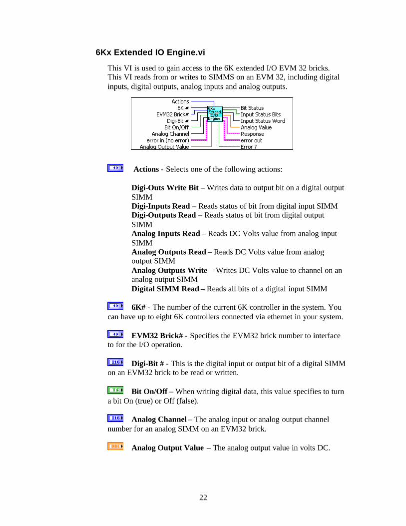
6Kx Extended IO Engine.vi
This VI is used to gain access to the 6K extended I/O EVM 32 bricks. This VI reads from or writes to SIMMS on an EVM 32, including digital inputs, digital outputs, analog inputs and analog outputs.
Actions - Selects one of the following actions:
Digi-Outs Write Bit – Writes data to output bit on a digital output SIMM Digi-Inputs Read – Reads status of bit from digital input SIMM Digi-Outputs Read – Reads status of bit from digital output SIMM Analog Inputs Read – Reads DC Volts value from analog input SIMM Analog Outputs Read – Reads DC Volts value from analog output SIMM Analog Outputs Write – Writes DC Volts value to channel on an analog output SIMM Digital SIMM Read – Reads all bits of a digital input SIMM
6K# - The number of the current 6K controller in the system. You
can have up to eight 6K controllers connected via ethernet in your system.
EVM32 Brick# - Specifies the EVM32 brick number to interface to for the I/O operation.
Digi-Bit # - This is the digital input or output bit of a digital SIMM on an EVM32 brick to be read or written.
Bit On/Off – When writing digital data, this value specifies to turn a bit On (true) or Off (false).
Analog Channel – The analog input or analog output channel number for an analog SIMM on an EVM32 brick.
Analog Output Value – The analog output value in volts DC.
23
Bit Status – Indicates whether the digital bit read is On (true) or Off (false).
Input Status Bits – A boolean array that represents a 32-bit value for an entire EVM32 brick. For example, if one EVM32 brick has 4 digital input SIMM modules a 32 bit array is returned.
Input Status Word - This represents the unsigned 32-bit value for an EVM32 brick’s digital input simm modules.
Analog Value – The analog input value in volts DC.
Response – The string that is returned by the 6K controller after a write or read command.
Error ? – Indicates if an error occurs while trying to read or write to the 6K during EVM32 extended I/O commands.
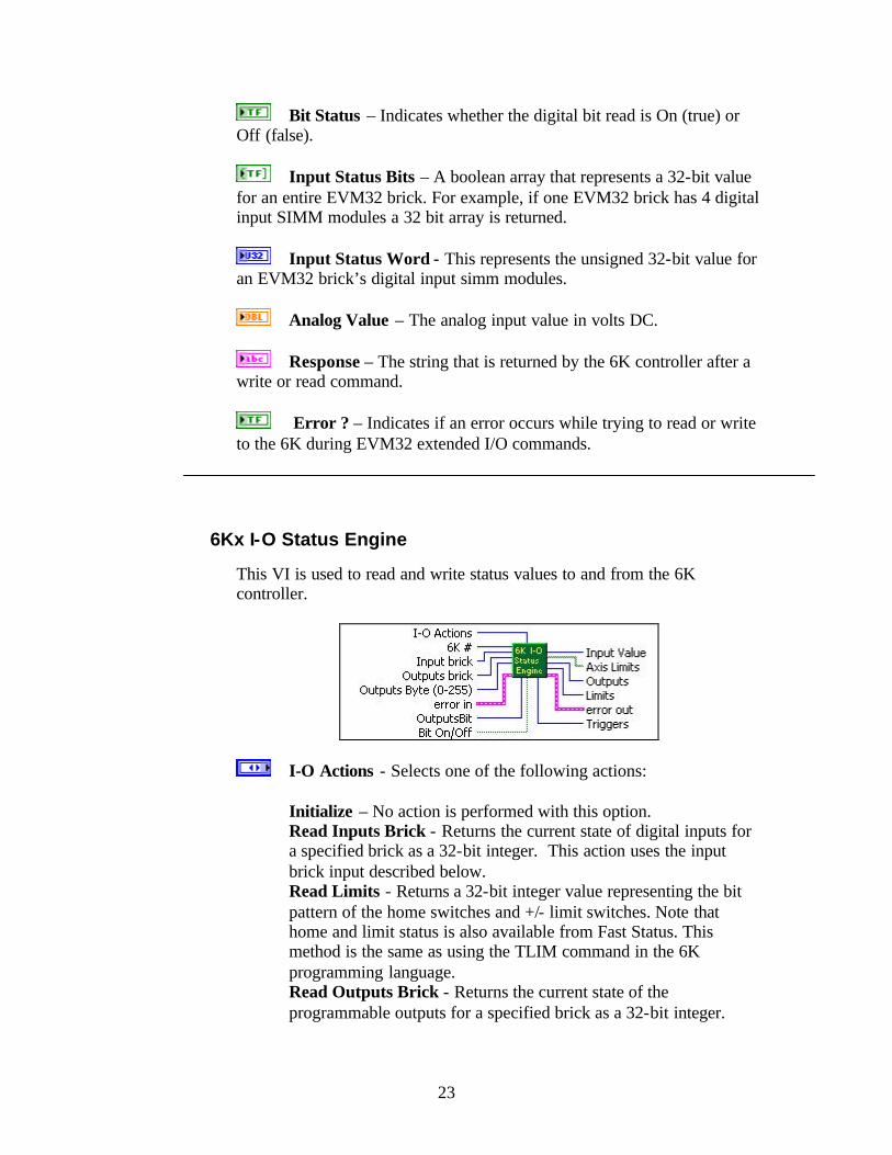
6Kx I-O Status Engine
This VI is used to read and write status values to and from the 6K controller.
I-O Actions - Selects one of the following actions: Initialize – No action is performed with this option. Read Inputs Brick - Returns the current state of digital inputs for a specified brick as a 32-bit integer. This action uses the input brick input described below. Read Limits - Returns a 32-bit integer value representing the bit pattern of the home switches and +/- limit switches. Note that home and limit status is also available from Fast Status. This method is the same as using the TLIM command in the 6K programming language. Read Outputs Brick - Returns the current state of the programmable outputs for a specified brick as a 32-bit integer.

24
Read Trigger Inputs - Returns the trigger interrupt status as a 32-bit integer. This requires Fast Status to be enabled (which is default for the 6Kx Comm Engine VI). This method is the same as using TTRIG in the 6K programming language. Write Outputs Byte - Writes an unsigned 8-bit integer (0-255) pattern to the specified outputs brick. Write Output Bit - Writes a boolean T/F to the specified bit on a specified outputs brick.
6K # - The number of the current 6K controller. You can have up
to eight 6K controllers connected via ethernet in your system.
Input brick - The number of the 6K Digital EVM32 Extended I/O Input Brick or onboard I/O. Onboard inputs are represented by a value of 0. Extended inputs, or EVM32 Input SIMMS, are represented by values of 1 and above. This value is used by the Read Inputs Brick action.
Outputs brick - The number of the 6K Digital EVM32 Extended I/O Output Brick or onboard I/O. Onboard Outputs are represented by a value of 0. Extended outputs, or EVM32 Output SIMMS are represented by values of 1 and above. This value is used by the Read Outputs Brick, Write Outputs Byte and Write Outputs Bit actions.
Outputs Byte (0-255) - Bit pattern (0-255) that will be written to an output port or output brick on the 6K controller.
Outputs Bit - Bit to be written on a 6K controller's onboard outputs or EVM32 outputs brick.
Bit On/Off – Sets the state of the output bit to be written to either on or off.
Input Value - Value returned by the Read Inputs Brick action. Onboard inputs are represented by a value of 0. Extended inputs, or EVM32 Input SIMMS, are represented by values of 1 or above.
Axis Limits - Boolean array representation of the 32-bit integer that represents the Home/Limits status. Returned by Read Limits action.
Outputs - Output port or brick pattern returned by Read Outputs Brick.
Limits – A 32- integer status word representing TLIM home and limits status returned by the Read Limits action.

25
Triggers - Value returned by the Read Trigger Inputs action that represents the trigger interrupt status. Reference the TTRIG command in the “6K Series Command Reference” manual for more information.
6Kx Read-Write Engine.vi
This VI is used to write commands, read or write variables, and send or read program files to and from the 6K controller.
SendVariableStructure – A cluster containing arrays of VARIS, VARS, and VARBS to send to the 6K controller. Values for a mask and reserved variables are also included in the cluster.
Action - Selects one of the following actions:
Initialize – No action is performed with this option. Write Command – The Write Command transmits 6K language commands to the 6K controller. This action takes as an input a 6K language formatted command string, appends a CR/LF to the string and then performs a Write with Blocking Method to the Com6srvr.INet with a two second timeout. Send File - Takes as an input a string control "6K Filename" with the Path and Filename of a 6K Language .PRG file and sends the file to the 6K controller. Run Program Label - Transmits to the 6Kcontroller a program label name that exists in the 6K Language .PRG file, causing the 6K controller to run the specified motion algorithm. Get File - Reads the current file residing in the 6K controller memory and opens a Windows dialog box with a select list of the motion algorithms in the 6K controller. You may highlight program labels that you wish to save and then click on save. You will then be prompted with a Windows file dialog box to save the file and where to save the .prg file.

26
Read - Reads the input buffer from the 6K controller and returns the data in string format. Send Variable Packet - Sends the contents of a LabVIEW cluster named “Send Variable Structure to the 6K.ctl” to the 6K controller. User Status Register - Performs a read of the 6K User Status and returns a 32-bit integer result. Read Binary Variable - Returns the value of the specified binary variable as a 32-bit integer. Note: This will only read VARB1 through VARB8. To read VARB's above VARB8 use the "Read any VARx with Response.vi". Read Long Int VARI1-10 - Returns the value of the specified integer variable as a 32-bit integer. Note: This will only read VARI1 through. VARI10. To read VARI's above VARI10 use the "Read any VARx with Response.vi". Read Float VARs 1-12 - Returns the value of the specified floating point variable as a double. Note: This will only read VAR1 though. VAR12. To read VAR's above VAR12 use the "Read any VARx with Response.vi".
Variable Bin - Value of the 6K boolean variable VARB to be written to the 6K controller. This variable can only be used with VARB1-8. To use VARBs beyond 1-8, use the VI named Write any VARx with Response.vi.
6K # - The number of the current 6K controller in the system. You can have up to eight 6K controllers connected via ethernet in your system.
cmd stg - Formatted 6K Motion Language command string.
6K Filename - Path and filename of the 6K Motion Language .prg file to be downloaded to the 6K controller.
Program Label - 6K Motion Language program label to be run, such as a motion algorithm that exists in the 6K program memory that can be run by calling its label.
Variable to Read - The number of the 6K variable to be read. This is used to read VAR1-12, VARB1-8 and VARI1-10. Specify only the number of the variable to read. Thus, to read binary variable 7, input a 7 for this argument. To read any variables beyond these use the VI named Read any VARx with Response.vi.
Var.Type - Used for writing variables to the 6K controller. Specifies the variable type: Binary, Float or Integer. This is used to write to VAR1-12, VARB1-8 and VARI1-To write to variables beyond these use the VI named Write any VARx with Response.vi.

27
Var.# 1-12,1-8 -. Specifies the variable number to write to the 6K
controller. This is used with methods that can write only to VAR1-12, VARB1-8 and VARI1-12. To write to variables beyond these use the VI named Write any VARx with Response.vi.
Variable Dbl – Float variable to be written to the 6K controller. This variable can only be used with VAR1-12. To use VARs beyond 1-12, use the VI named Write any VARx with Response.vi.
Variable Int - Integer variable to be written to the 6K controller. This variable can only be used with VARI1-12. To use VARIs beyond 1-12, use the VI named Write any VARx with Response.vi.
Read Response – Response from the 6K controller after performing the read.
Read Stg Returned - String that is read from the 6K controller input buffer.
UserStatus - Returns the value of the user status register in the 6K controller.
Vari - Integer variable read from the 6K controller. Applies only to VARI's 1-10. To read VARI's beyond 1-10 use the VI named Read any VARx with Response.vi.
VarB - Boolean variable read from the 6K controller. Applies only to VARB's 1-8. To read VARB's beyond 1-8 use the VI named Read any VARx with Response.vi.
Float Var - Float variable read from the 6K controller. Applies only to VAR's 1-12. To read VAR's beyond 1-12 use the VI named Read any VAR with Response.vi.
6Kx System Status Engine.vi
This VI is used to request and read various status registers or status structures in the 6K controller.

28
Action – Selects one of the following actions:
Initialize – Performs no action. This is the default action. Request Fast Status Update - Allows the Com6srvr.INet to request a Fast Status update as needed without having to enable the fast status "streaming mode" (FSEnabled) or set up an update interval (FSUPDateRate). Alarm Status - The Alarm Status property returns the state of the 6k controller's alarm status. See the INTHW command in the 6K command reference for more information. Specifying a bit value of zero will return the entire 32 bit alarm status as a32-bit integer. Otherwise if a bit other than zero is specified, that bit will be returned. The state of the controller’s alarm status can also be obtained by the Fast Status structure. Command Count - Returns the number of 6K commands that have been executed (outside of defined programs) since the controller was powered up. This count can also be obtained by the Fast Status structure System Time Counter - Returns the current time frame counter value. The time frame counter is a free running counter in the 6K controller. The counter is updated at the 6K system update rate which defaults to 2 milliseconds. This requires Fast Status to be enabled. The time frame counter can also be obtained by Fast Status structure. Error Status - The error status property returns the current error status of 6K task 0 only (TER). It requires that Fast Status be enabled. See the TER command in the 6K Command Reference for more information. The error status of task 0 can also be obtained by the Fast Status structure. Fast Status - Returns the entire Fast Status data structure. This property allows for faster, more efficient retrieval of the Fast Status structure. See the 6K User Guide Addendum for more information. System Status - Returns the system status for task 0 only in the 6K (TSS). See the TSS command in the 6K Command Reference for more information. The system status can also be obtained by the Fast Status structure.

29
Timer Status - Returns the current timer value (TTIM) for task 0 only. See the TTIM command in the 6K Command Reference for more information. The timer status can also be obtained by the Fast Status structure.
6K # - The number of the current 6K controller in the system. You can have up to eight 6K controllers connected via ethernet in your system.
Alarm Status Bit – This value specifies the bit(s) to query the alarm status. Specifying a bit value of zero will return the entire 32-bit alarm status as a 32-bit integer. Otherwise, if a bit other than zero is specified, that bit will be returned. See the INTHW command in the 6K Command Reference for details.
Alarm Status – The alarm status property returns the state of the 6K controller’s alarm status. See the INTHW command in the 6K Command Reference for more information. The state of the controller’s alarm status is also returned in the Fast Status structure.
Alarm Bit - Returns the specified alarm status bit value.
System Status - Returns the system status for task 0 only in the 6K controller (TSS). See TSS in the 6K command reference for details. This can also be obtained by Fast Status Structure.
Timer - Returns the current timer value (TTIM) for task 0 only. See TTIM in the 6K Command Reference for more information. The timer value is also returned by the Fast Status structure.
Fast Status - Returns the entire Fast Status data structure. This property allows for faster, more efficient retrieval of the Fast Status structure. See the 6K User Guide Addendum for more information. The following parameters are returned by Fast Status (with the exception of VAR ((F612)) and Ext.Fast Status:
UpdateID As Integer ‘ Reserved for internal use Counter As Integer ‘ time frame counter (2ms per count) MotorPos(1 To 8) As Long ‘ commanded position (counts) EncoderPos(1 To 8) As Long ‘ actual position (counts) MotorVel(1 To 8) As Long ‘ commanded velocity (counts/sec) AxisStatus(1 To 8) As Long ‘ axis status (TAS) SysStatus As Long ‘ system status (TSS) ErrorStatus As Long ‘ error status (TER) UserStatus As Long ‘ user status (TUS) Timer As Long ‘ timer value (TIM - milliseconds) Limits As Long ‘ limit status (TLIM) ProgIn(0 To 3) As Long ‘ programmable input status (TIN)

30
ProgOut(0 To 3) As Long ‘ programmable output status (TOUT) Triggers As Long ‘ trigger interrupt status (TTRIG) Analog(1 To 2) As Integer ‘ lo-res analog input voltage (TANV) VarB(1 To 10) As Long ‘ VARB1 - VARB10 VarI(1 To 10) As Long ‘ VARI1 - VARI10 Reserved As Long ‘ Reserved for internal use CmdCount As Long ‘ Command Count (from comm port) Var(1 To 12) As Double ‘ real variables VAR1..VAR12
TSS-Transfer SYS Status - Returns the system status for task 0 only in the 6K (TSS). See the TSS in the 6K Command Reference for more information. The system status is also returned by the Fast Status structure. This cluster contains the same information as the system status output status but brings out each status value for a boolean value.
Command Count - Returns how many 6K commands have been executed (outside of defined programs) since the controller was powered up. This count is also return by the Fast Status structure.
Sys.Time Frame Counter - Returns the current time frame counter value. The time frame counter is a free running counter in the 6K controller. The counter is updated at the 6K system update rate with the default to 2 milliseconds. This requires Fast Status to be enabled. The time frame counter can also be obtained by the Fast Status structure.
12.2 Function VI Reference
4 Axis Accel Select.vi
This VI sets the acceleration parameter in a 6K controller for a single axis in the range of 1-4. This VI could easily be modified or adapted to set the acceleration parameters for an 8-axis controller.
Select Axis - 4 axis numeric selector used to pick a single axis 1 through 4 to set acceleration in the 6K controller.
Acceleration – Acceleration parameter for a single axis in units/sec 2. Units are determined by how the user configured the 6K .prg program’s motion scaling SCLA, SCLV, SCLD.

31
Set Accelerations Type – This parameter returns a cluster of booleans indicating which axis is selected, and a cluster of accelerations for each axis.
4 Axis Decel Select.vi
This VI sets the deceleration parameter in a 6K controller for a single axis within the range of axes 1-4. This VI could easily be modified or adapted to set the acceleration parameters for an 8-axis controller.
Select Axis - 4 axis numeric selector used to pick a single axis 1
through 4 to set the deceleration parameters in the 6K controller.
Deceleration – Deceleration parameter for a single axis in units/sec 2. Units are determined by how the user configured the 6K .prg program’s motion scaling SCLA, SCLV, and SCLD.
Set Decelerations Type – This parameter returns a cluster of booleans indicating which axis is selected, and a cluster of deceleration for each axis.
4 Axis Velocity Select.vi
This VI is used to set the velocity parameter in a 6K controller for a single axis within the range of axes 1-4. This VI could easily be modified or adapted to set the acceleration parameters for an 8-axis controller.
Select Axis - 4 axis numeric selector used to pick axis 1 through 4 to set the velocity in the 6K controller.
Velocity -Velocity parameter for a single axis in units/sec. Units are determined by how the user configured the 6K .prg program's motion scaling SCLA, SCLV, and SCLD.
Set Velocity Type - This parameter returns a cluster of booleans indicating which axis is selected, and a cluster of velocities for each axis.

32
6K arpBat.vi
This VI executes a DOS command to run the 6K ARP batch file.
Command to execute - This argument contains the path and filename for the 6K ARP batch file.
Error – This is the system dependent exit code that the command returns.
6Kx Axes Status Parser.vi
This VI extracts the most commonly used motion status bits and position for up to 8 axes from the Fast Status data structure.
Actions – These are the actions performed using this VI.
Initialize – Sets the 6K controller axis status parser to scale raw motion counts to engineering units in inches or millimeters, depending upon how the 6K motion .prg file is written and how the SCLD command is used. Status - Parses the Ext.Fast Status structure to the most commonly used motion status bits and position for 8 axes. The parsed values are then combined into a cluster and returned in the Axes Status structure.
Fast Status – The incoming Ext.Fast Status structure to be parsed.
Axes Status - Custom motion status cluster that contain the most
commonly used motion status bits and position variables for up to 8 axes.
6Kx Comm Launcher.vi
This VI reads the 6Kx_Config.ini file, runs the ARP batch file to statically map the IP address of the 6K controller, calls the connect method in the 6K Comm Engine, sets the ethernet watchdog parameters, sets Fast Status parameters and enables Fast Status, then it runs a kill and erases a VI to kill the 6K controller and erase its program memory. This VI can send the

33
6K .prg files and run 6K program labels to perform setups or configurations at launch time.
Map IP Addresses - If True, the 6K ARP batch file is executed.
Send Main Prog.Files - If True, the .PRG file specified by 6K Path & Filenames is downloaded to the 6K controller.
Run Program Labels - If True, setup or 6K configuration program algorithms in the 6K controller are executed.
Kill & Erase 6Kx's - If True, the 6K controller execution is killed and its program memory is erased.
6K program labels - Array of 6K .PRG program labels that call setup or configuration programs in the 6K controller.
6Kx Path & Filenames – The path and filename specifying the location of the .PRG file to download to the 6K controller.
IP Address & Axes – Two-dimensional table of 6K communication parameters for IP address, number of axes and Fast Status update rate in milliseconds for each 6K controller in the system.
6Kx Error Handler.vi
This VI loads the LabVIEW Error cluster with Com6srvr.Inet errors.
6K Com6srvr Error Codes: -1 Bad ethernet connection due to socket error -2 Ethernet connection was shut down -3 Connection attempt failed -4 Maximum number of ethernet connections exceeded -5 Ethernet or RS-232 connection not ye t established -6 No file name specified
34
-7 Unable to locate specified file -8 Unable to open specified file -9 Unable to ping ethernet connection -10 Unable to create ethernet socket -11 Invalid parameter passed to function -12 Unable to create or connect ethernet watchdog socket -13 Unable to create or connect ethernet fast status socket -14 Unable to create or connect ethernet alarm socket -15 Unable to create or connect ethernet command socket -16 Unable to create client ring buffer for ethernet command socket -17 SetWatchdog returns this error when Windows runs out of timers -18 Ethernet watchdog timeout error detected by 6Kx Comm Engine.vi
6Kx Run Program Label.vi
This VI makes calls to the 6K controller(s) to run 6K setup or configuration programs in the 6Kx Comm Launcher VI.
6K Program Labels - The 6K program labels control is an array of strings that should have a 1:1 relationship with each 6K controller in the system. For example,
Array element zero = 6K controller #1's setup or configuration program label; Array element one = 6Kcontroller #2's setup or configuration program label, etc.
6Kx Send File.vi
This VI sends a 6K motion language .prg file to the 6K motion controller.
6Kx Filenames – The 6k filenames control is an array of path and filenames of 6K motion language .prg files that should have a 1:1 relationship with each 6K controller in the system. For example,
Array element zero = .prg file associated with the first 6K controller in the system; Array element one = .prg file associated with the second 6K controller in the system, etc.

35
6Kx Wait for Read Response.vi
This VI is most often called by other VIs. For example, Read any VARx with Response.vi, and Write any VARx with Response.vi each call this VI. This VI's purpose is to assist with reading from or writing to any 6K variables. This VI verifies that the 6K controller produced the correct response, with a terminating character, after the caller VI performed a read or write operation to the 6K controller. This VI protects itself from hanging with a timeout, and records the elapsed time taken to perform the wait for response operation.
Com6srvr.Inet - Com6srvr.INet Active X object handle.
Stg. to Wait for - This is the correct response string that should be returned from the 6K controller when a read operation is performed. If this string is not received from the 6K controller before the timeout is executed, a timeout error occurs.
Dwell (10) (msec) - Dwell time specifies when this VI queries the 6K controller for read responses. The default dwell time is 10 msec.
Timeout (5sec) - Timeout is the amount of time in seconds given for the 6K controller to respond correctly to the read or write operation. If this timeout value is exceeded, the VI stops waiting for the correct response and completes execution with a timeout error. The default timeout is 5 seconds.
Read or Write – Boolean value that sets the type of operation. Read = False, Write = True
Com6srvr.Inet Out - Com6srvr.INet Active X object handle.
Read Response - Read response characters returned from the 6K controller.
Elapsed Time - The elapsed time in milliseconds for the 6K controller to respond to the read or write operation.
Timeout - If True, a timeout error occurs because the 6K controller did not respond correctly to the read or write operation.

36
Binary Variables Parser.vi
This VI takes as its input the Ext.Fast Status cluster from the 6Kx System Status Engine.vi-Fast Status case, which returns the entire Fast Status data structure. The VarB array is indexed and parsed to output boolean arrays that represent VARB1 through VARB8.
Fast status – The incoming Ext.Fast status structure to be parsed.
VARB1..8 – These eight arrays are filed with data currently in the 6K controllers VARB1..8 memory locations.
Check 6K number selected.vi
This VI verifies that the number of the 6K controller that the user wants to address is actually in the system. This VI queries the 6Kx configuration engine for valid 6K controllers identified in the system. For example, if there are two 6K controllers in the system (as defined in the 6K configuration INI file) and the user selects 6K number 3 which does not exist, this VI will flag an error letting the user know that an incorrect 6K controller has been selected.
6K # - The number of the 6K controller that has been selected.
# of 6K's in the System - The number of 6K controllers that have been identified in the system.
6K # Out - The correct 6K controller number or a default of the highest number 6K controller in the system if an invalid 6K controller is specified.
Convert 6K Bool to Binary.vi
This VI is used as a sub VI in Read any VARx with Response.vi to convert the VARB string returned from the controller to an unsigned 32-

37
bit value (U32). For example, if the VARB string returned from the 6K controller is 1111_1110_1100_1000_0001_0011_0111_1111 its binary format is as follows: 11111110110010000001001101111111 which converts to an unsigned 32-bit value (U32) of 4274525055
6K Varb Boolean Pattern - VARB string obtained from the 6K controller.
VARBx Out - The unsigned 32-bit representation of VARB.
Convert Axis select slider to GO string.vi
This VI creates a 6K language formatted GO command string 4 axis selector slider control. This VI can easily be revised to work on an 8 axes selector control.
Axis – Control for selecting a single axis 1 through. 4. This can be changed to manage 8 axes.
6K Go Command String - 6K Language GO command string that is sent to the axis specified.
Convert Exended fast status.vi
This VI takes as an input a variant type returned by the Com6srvr.INet Active X object and parses it to the extended Fast Status structure type and elements in the extended Fast Status cluster. This VI is used as a sub VI in the 6Kx System Status Engine.vi. This VI is used as a sub VI in the 6Kx System Status Engine.vi.
raw fast status - Variant type returned by the Com6srvr.INet Active X object.
Ext.Fast status - The Fast Status data structure. See the Com6SRVR Programming Notes in the COM6SRVR Corrections &

38
Enhancements Section contained in the 6K User Guide Addendum for description of the Fast Status data structure.
Convert ExtFastStatus variant to DBLs.vi
This VI parses the Extended Fast Status variant to extract the 6K controller float variables VAR1-12. This VI is a sub VI of the Convert Extended Fast Status.vi.
Extended Fast Status Variant In – This is the raw Fast Status variant passed in from the extended Fast Status property from the Com6srvr.exe.
Index Offset - The index or pointer in the variant array where VARs#1-12 are located.
VARs 1-12 – Values of float variables 1-12 in the 6K controller’s memory.
Convert fast status.vi
This VI is used as a sub VI in the 6Kx System Status Engine.vi. This VI takes as an input a variant type returned by the Com6srvr.INet Active X object and parses it to the Fast Status structure type and elements in the Fast Status cluster.
raw fast status - Variant type returned by the Com6srvr.INet Active X object.
Fast Status - Entire Fast Status data structure. See the Com6SRVR Programming Notes in the COM6SRVR Corrections & Enhancements Section contained in the 6K User Guide Addendum for description of the Fast Status data structure.
Convert send variable structure.vi
This VI is used in the Send Variable Packet case of the 6Kx Read-Write Engine.vi. This VI formats arrays of I32s for VARIs #1-12, I32's for

39
VARBs 1-8 and DBLs for VARs #1-12 to a variant data type that the Com6srvr.exe's Send Variable Packet requires.
SendVariableStructure - This cluster contains arrays of I32s for VARs #1-12, I32s for VARBs 1-8 and DBLs for VARs #1-12 as well as other reserved variables that are required.
Raw SendVariableStructure - Variant out that is formatted to the structure that the 6K Com6srvr.exe requires.
Convert TIN status string to numeric.vi
This VI converts a string returned by the 6K controller when LabVIEW requests a transfer input status command (TIN) to a numeric and boolean array.
TIN String – Transfer input status string read from the 6K controller by another LabVIEW VI.
6K TIN Input Status word out – The value of the data portion of the input TIN string represented as an unsigned 32-bit integer.
6K TIN Input Status – The value of the data portion of the input TIN string represented as a boolean array.
6K Varb String Out – Modified string from the TIN string input before being converted to U32 and boolean arrays. This string can be examined to verify proper formatting of the converted string.
Create GO command.vi
This VI forms a 6K motion language GO command based upon the switch configuration in the Set Axis to Move cluster, then writes the command to the 6K controller to start the motion.

40
6K # - The number of the 6K controller in the system on which to
execute motion.
Set Axis to Move - Selects the appropriate switches for the axes that you do or do not want to move. A boolean array of switches which allows the user to select the axis or axes on which motion is to be executed.
Deadband check 6K VARs.vi
When downloading variables from the computer to the 6K controller for motion recipes, you may need to check that what the computer sent to the 6K controller has been received by the 6K controller. This is referred to as a recipe variables confirmation. This deadband checker inputs the recipe variables confirmation and filters the decimal portion of the value to the precision requested. For example, if the computer sends the 6K controller VAR99 = 1.2345 and the 6K controller returns 1.23450002, the recipe confirmation will fail unless the value is filtered after four decimal places.
Scalar or Array, Array=T – If true, the array inputs are used to perform the filtering. If false, the scalar inputs are used to perform filtering.
Written to 6K - The scalar value that was written to the 6K controller.
Read from 6K - The scalar value that was read back from the 6K controller in order to perform a confirmation.
What was written to 6K - Array that was sent to the 6K controller.
What was read back from 6K - Array that was read back from the 6K controller in order to perform a confirmation.
Deadband precision - The number of decimal places to confirm.
Confirmation Failures - Array of status bits that indicates which variables failed the confirmation.
41
Failure – Boolean that indicates if the scalar value failed the
confirmation.
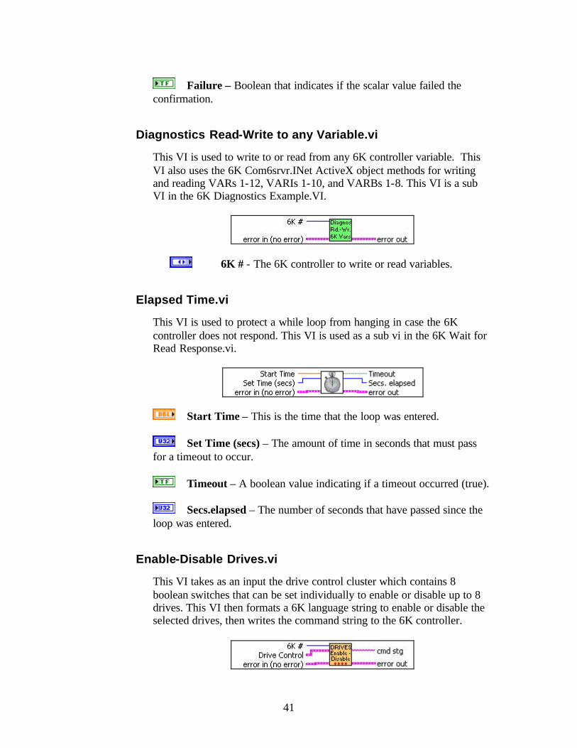
Diagnostics Read-Write to any Variable.vi
This VI is used to write to or read from any 6K controller variable. This VI also uses the 6K Com6srvr.INet ActiveX object methods for writing and reading VARs 1-12, VARIs 1-10, and VARBs 1-8. This VI is a sub VI in the 6K Diagnostics Example.VI.
6K # - The 6K controller to write or read variables.
Elapsed Time.vi
This VI is used to protect a while loop from hanging in case the 6K controller does not respond. This VI is used as a sub vi in the 6K Wait for Read Response.vi.
Start Time – This is the time that the loop was entered.
Set Time (secs) – The amount of time in seconds that must pass for a timeout to occur.
Timeout – A boolean value indicating if a timeout occurred (true).
Secs.elapsed – The number of seconds that have passed since the loop was entered.
Enable-Disable Drives.vi
This VI takes as an input the drive control cluster which contains 8 boolean switches that can be set individually to enable or disable up to 8 drives. This VI then formats a 6K language string to enable or disable the selected drives, then writes the command string to the 6K controller.
42
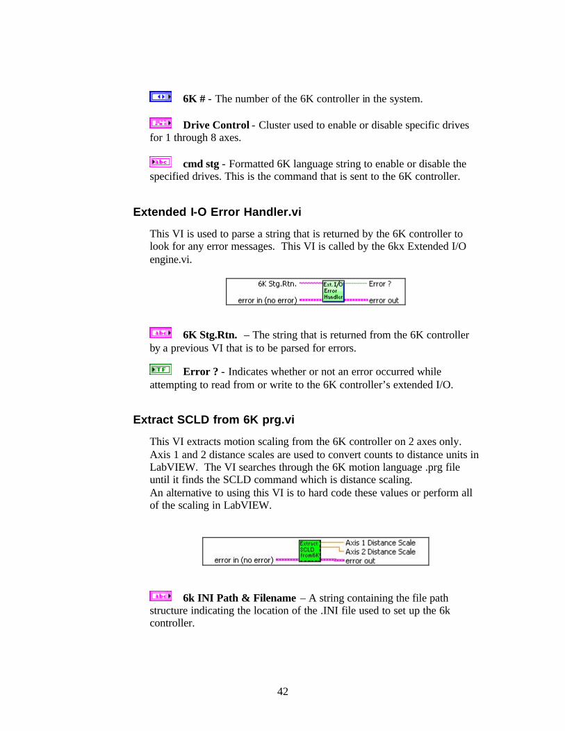
6K # - The number of the 6K controller in the system.
Drive Control - Cluster used to enable or disable specific drives for 1 through 8 axes.
cmd stg - Formatted 6K language string to enable or disable the specified drives. This is the command that is sent to the 6K controller.
Extended I-O Error Handler.vi
This VI is used to parse a string that is returned by the 6K controller to look for any error messages. This VI is called by the 6kx Extended I/O engine.vi.
6K Stg.Rtn. – The string that is returned from the 6K controller by a previous VI that is to be parsed for errors.
Error ? - Indicates whether or not an error occurred while attempting to read from or write to the 6K controller’s extended I/O.
Extract SCLD from 6K prg.vi
This VI extracts motion scaling from the 6K controller on 2 axes only. Axis 1 and 2 distance scales are used to convert counts to distance units in LabVIEW. The VI searches through the 6K motion language .prg file until it finds the SCLD command which is distance scaling. An alternative to using this VI is to hard code these values or perform all of the scaling in LabVIEW.
6k INI Path & Filename – A string containing the file path structure indicating the location of the .INI file used to set up the 6k controller.

43
Axis 1 Distance Scale – This value contains the distance units for axis 1. This can be pulses per inch, millimeters or revolutions, depending upon the application and how you set up your scaling in the 6K .prg.
Axis 2 Distance Scale - This value contains the distance units for axis 2. This could also be pulses per inch, or millimeters or revolutions. It depends upon your application and how you set up your scaling in the 6K .prg.
Kill & Erase.vi
This VI is used as a sub VI in the 6Kx Comm Launcher.vi. Its purpose is to send a kill command to the 6K controller to terminate all 6K tasks, and erase the 6K controller's program memory.
6K # - The number of the current 6K controller in the system. You can have up to eight 6K controllers connected via ethernet in your system.
KILL Motion.vi
This VI sends a kill immediate command to the 6Kcontroller to kill all motion and tasks. Important: This VI should be placed in a separate loop, apart from a loop that is managed by other user interface actions or front panel objects, so that the kill will actually be serviced.
6K # - The number of the 6K controller in the system that you want to kill all motion operations.
Minimize Path.vi
This VI takes a path with an .llb or .exe filename extension and returns the path without the extension.
Inpath – Full pathname used to access an .llb or .exe filename.

44
Outpath – Returns the path with any .exe and .llb extensions stripped from the path.
Move Axis.vi
This VI is used to select one of four axes, set its distance and direction, and then send the 6K controller a formatted 6K language string to execute the move.
6K # - Number of the 6K controller in the system that you want to move.
Move to Position - Position to move to in distance units. NOTE: This is dependent upon how you set up the system's motion scaling; for example, raw counts, inches, millimeters or revolutions.
Direction – True indicates counter clockwise motion and false indicates clockwise motion.
Axis – A 4 axis slider control that is used to select the axis on which to specify distance, direction and then move.
Parse Setup Params.vi
This VI is used to parse strings read from the 6Kx_Config.ini file to a 2D array of strings. This is a sub VI in the Read 6kx INI File.vi.
Actions – An option to parse (0) strings to a 2D array of strings or query (1) the array of strings.
6Kx Info In - Array of strings read from 6K_Addr Ini file key. Each array element corresponds to a 6k controller configuration string.
IP addr & Axes Out - Formatted dimension array of strings containing IP addresses, the number of axes per 6K controller and Fast Status update rate (milliseconds).
45
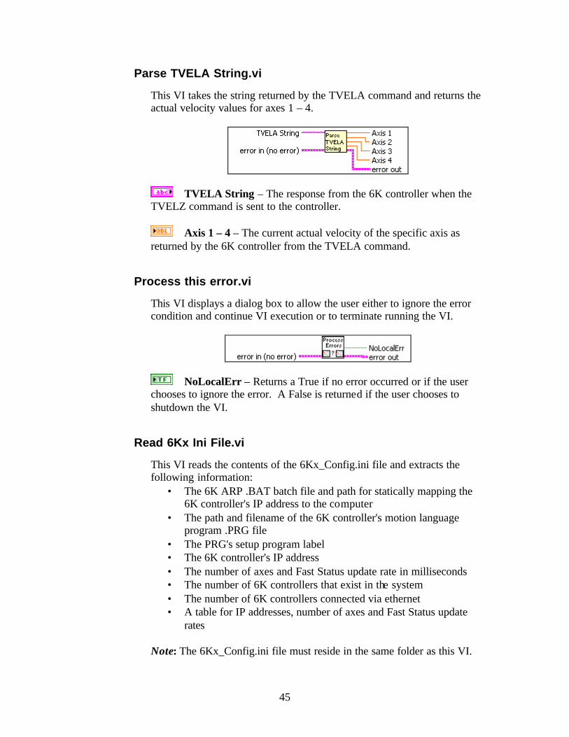
Parse TVELA String.vi
This VI takes the string returned by the TVELA command and returns the actual velocity values for axes 1 – 4.
TVELA String – The response from the 6K controller when the TVELZ command is sent to the controller.
Axis 1 – 4 – The current actual velocity of the specific axis as returned by the 6K controller from the TVELA command.
Process this error.vi
This VI displays a dialog box to allow the user either to ignore the error condition and continue VI execution or to terminate running the VI.
NoLocalErr – Returns a True if no error occurred or if the user chooses to ignore the error. A False is returned if the user chooses to shutdown the VI.
Read 6Kx Ini File.vi
This VI reads the contents of the 6Kx_Config.ini file and extracts the following information:
• The 6K ARP .BAT batch file and path for statically mapping the 6K controller's IP address to the computer
• The path and filename of the 6K controller's motion language program .PRG file
• The PRG's setup program label • The 6K controller's IP address • The number of axes and Fast Status update rate in milliseconds • The number of 6K controllers that exist in the system • The number of 6K controllers connected via ethernet • A table for IP addresses, number of axes and Fast Status update
rates Note: The 6Kx_Config.ini file must reside in the same folder as this VI.

46
Configuration file path – The filename and path of the INI file from which to extract information.
# of 6Ks – Returns the number of 6K controllers in the system as specified in the INI file.
6K_ARP – The 6K controller's ARP batch filename and path.
6K Program Path+File - An array of 6K program names, filenames, and paths.
6K IP addr & Axes Out – 2-dimensional table of 6K communication parameters for IP address, number of axes and Fast Status update rate in milliseconds for each 6K controller in the system.
Setup Label Name - An array of 6K PRG program labels that will run 6K controller setups or configurations inside the 6K controller.
Address Config - An array of 6K controller communication parameters for IP address, number of axes and Fast Status update rate in milliseconds for each 6K controller in the system.
6K IP addr & Axes Out - 2D table of 6K communication parameters for IP address, number of axes and Fast Status update rate in milliseconds for each 6K controller in the system.
Read any VARx with Response.vi
This VI is used to read any 6K variable in the 6K Com6srvr.INet Active X object. This allows LabVIEW to access beyond the first 12 floats, first 12 integers and first 8 boolean variables in the 6K controller.

47
Type of Variable - Selects the type of variable to read, VAR floats, VARI integers, and VARB booleans.
6K # - Selects the number of the 6K controller in the system to read variables from.
VARx# to Read - The number of the variable that you wish to read from the 6K controller.
Dwell (mSec) - Dwell time controls when this VI queries the 6K controller for read responses. This allows the user to read a variable at a specific time.
Timeout(Sec) - Timeout is the set time of the error timer to break this VI out of the wait for response loop and detect that the 6K controller did not respond correctly to the read operation.
Float - VAR float variable read from the 6K controller.
Integer - VARI integer variable read from the 6K controller.
VARBx Out - VARB boolean variable read from the 6K controller.
Timeout! – A boolean that is True if a timeout occurred.
Elapsed time (mSec) - The elapsed time in milliseconds it took for the 6K controller to respond to the read operation.
Read Characters From File.vi
This VI reads a specified number of characters from a file.
file path (dialog if empty) – The path and filename to be read.
number of characters (all:-1) – The number of characters to read.
New file path (not a path if cancelled) – The path of the file from which data was read.

48
character string – The data read from the file.
Mark after read (chars.) – The location of the file mark after the read. This points to the character in the file following the last character read.
EOF? – A True is returned if an attempt is made to read past the end of the file.
Read Float VARs 1-12.vi
This VI reads the float VARs 1-12 from the 6K controller. This VI is called by the 6Kx Read-Write Engine.vi.
6K # - 6K controller in the system that you wish to read float variables from.
VAR1-12 - Float VARs 1-12 read from the 6K controller.
Returned strings handler.vi
This VI parses the input string to determine if the 6K controller has returned a warning or error message. This VI is called by Write 6K command with Error checking.vi, and Write any VARx with Response.vi.
6K Returned String – The 6K return string to be parsed.
Select 6K Prg Label and execute.vi
This VI, used as a sub VI in the 6K Diagnostics demo example, provides an example of how to select a 6K language .prg program label, format a string in the 6K language, and then write it to the 6K controller.

49
6K # - The number of the 6K controller to be addressed.
6K .prg Motion Functions – A list of select functions which correspond to 6K components that are written to the 6K controller.
Set Accel.vi
This VI formats a 6K language command string to set the acceleration parameters on axes 1 through 8. The Set Accel cluster contains boolean switches to select the axes on which to set acceleration. The switches can also be set to not write the acceleration parameter to specific axes.
6K # - Number of the 6K controller in the system on which to set acceleration parameters.
Set Accel – Cluster which sets the axes and specifies the acceleration parameters to be written. The applied acceleration depends on how Motion Scaling is defined in the 6K controller. Units may be in revolutions/sec2, inches/sec2, millimeters/sec2 or raw counts/sec2.
Cmd Stg – Returns the formatted 6K language command string that was used to set the acceleration parameters in the 6K controller. This may be useful during troubleshooting.
Set Decel.vi
This VI formats a 6K language command string to set the deceleration parameters on axes 1 through 8. The Set Decel cluster contains boolean switches to select the axes on which to set deceleration. The switches can also be set to not write the deceleration parameter to specific axes.
6K # - Number of the 6K controller in the system on which to set deceleration parameters.
Set Decels – Cluster which sets the axes and specifies the deceleration parameters to be written. The applied deceleration depends on how Motion Scaling is defined in the 6K controller. Units may be in revolutions/sec2, inches/sec2, millimeters/sec2 or raw counts/sec2.

50
Cmd Stg – Returns the formatted 6K language command string that was used to set the deceleration parameters in the 6K controller. May be useful during troubleshooting.
Set Distance+Direction.vi
This VI formats a distance/direction command string in the 6K motion language, and writes the result to the 6K controller.
6K # - Number of the 6K controller in the system on which to set distance and direction parameters.
Set Distance – Cluster which sets the axes and specifies the distance and direction parameters to be written. The applied distance depends on how motion scaling is defined using the SCLD command in the 6K controller. Units may be in raw counts, revolutions, inches, or millimeters.
Cmd Stg – Returns the formatted 6K language command string that was used to set the distance parameters in the 6K controller. This may be useful during troubleshooting.
Set Homing+Home.vi
This VI formats a 6K language command string to set the chosen axes to be homed, and to set the home direction. The parameters are then sent to the 6K controller to perform the homing moves.
6K # - Number of the 6K controller in the system on which to perform homing.
Set Homing – Cluster which specifies the axes to be homed, and the homing directions.
Cmd Stg – Returns the formatted 6K language command string that was used to set the homing parameters in the 6K controller. This may be useful during troubleshooting.
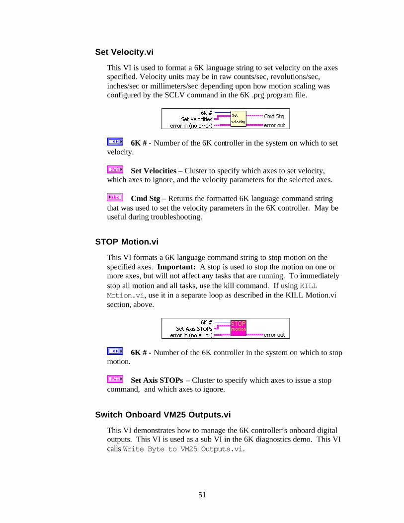
51
Set Velocity.vi
This VI is used to format a 6K language string to set velocity on the axes specified. Velocity units may be in raw counts/sec, revolutions/sec, inches/sec or millimeters/sec depending upon how motion scaling was configured by the SCLV command in the 6K .prg program file.
6K # - Number of the 6K controller in the system on which to set velocity.
Set Velocities – Cluster to specify which axes to set velocity, which axes to ignore, and the velocity parameters for the selected axes.
Cmd Stg – Returns the formatted 6K language command string that was used to set the velocity parameters in the 6K controller. May be useful during troubleshooting.
STOP Motion.vi
This VI formats a 6K language command string to stop motion on the specified axes. Important: A stop is used to stop the motion on one or more axes, but will not affect any tasks that are running. To immediately stop all motion and all tasks, use the kill command. If using KILL Motion.vi, use it in a separate loop as described in the KILL Motion.vi section, above.
6K # - Number of the 6K controller in the system on which to stop motion.
Set Axis STOPs – Cluster to specify which axes to issue a stop command, and which axes to ignore.
Switch Onboard VM25 Outputs.vi
This VI demonstrates how to manage the 6K controller’s onboard digital outputs. This VI is used as a sub VI in the 6K diagnostics demo. This VI calls Write Byte to VM25 Outputs.vi.

52
6K # - Number of the 6K controller in the system to turn on or off the onboard digital outputs.
6K Outputs - Boolean array that represents the output pattern to be written to the 6K controller’s onboard digital outputs. Note: The 6K2 and the 6K4 have four onboard digital outputs. The 6K6 and the 6K8 have eight onboard digital outputs.
Write 6K command with Error checking.vi
This VI writes commands to the 6K controller, waits for a response, and performs error checking on the string that is returned. In a multiple 6K controller application, this VI’s ability to wait for the response from the addressed controller prevents this VI from being called by other higher level VIs during the command and response. Note: We recommend using this VI for all 6K writes, instead of using Write 6K command.vi.
Com6srvr.Inet – Refnum from ActiveX automation server.
6K Cmd.String - Formatted 6K motion language command string to be transmitted to the 6K controller.
Dwell (10) (msec) - Dwell time controls when this VI queries the 6K controller for responses to the written command.
Timeout (5) (sec) - Timeout is the set time of the error timer to break this VI out of the wait loop and detect that the 6K controller did not respond correctly to the read or write operation.
Read(F) Write(T) - Boolean to set the type of operation, where: False = Read True = Write
Com6srvr.Inet Out – Pass through of the ActiveX automation
server refnum.

53
Read Response - The characters returned from the 6K controller in response to the written command.
Elapsed Time - The elapsed time in milliseconds it took for the 6K controller to respond to the write operation.
Timeout - If True, a timeout error occurred because the 6K controller did not respond correctly to the write operation.
Write any VARx with Response.vi
This VI writes to any 6K controller variable in the Com6srvr.Inet ActiveX object. This allows LabVIEW to write beyond the first 12 floats, first 12 integers, and first 12 boolean variables in the 6K controller.
Type of Variable - Selects the type of variable to write: VAR floats, VARI integers, or VARB booleans.
6K # - Selects the number of the 6K controller in the system to write variables to.
VARx# to Write - The number of the variable to write to in the 6K controller.
VAR - Float value to write to a 6K VAR variable.
VARI - Integer value to write to a 6K VARI variable.
VARB - Boolean value to write to a 6K VARB variable.
Dwell (mSec) - Dwell time controls when this VI queries the 6K controller for responses to the written command.
Timeout(Sec) - Timeout is the set time of the error timer to break this VI out of the wait for response loop and detect that the 6K controller did not respond correctly to the write operation.

54
Timeout ! - If True, a timeout error occurred because the 6K controller did not respond correctly to the write operation.
Elapsed time (mSec) - The elapsed time in milliseconds it took for the 6K controller to respond to the write operation.
Write Byte to VM25 Outputs.vi
This VI takes an unsigned 8-bit value to be written, formats a 6K language command string and writes it to the 6K controller to turn on the desired output bits. Note: The 6K2 and the 6K4 have 4 onboard digital outputs. The 6K6 and the 6K8 have 8 onboard digital outputs. See the 6K Series Hardware Installation Guide for instructions on connecting the 6K controller's outputs.
6K # - Number of the 6K controller in the system to turn on or off the onboard digital outputs.
Outputs Byte (0-255) - 8 bit value to be written to the 6K controller's onboard digital outputs. Note: The 6K2 and the 6K4 have 4 onboard digital outputs. The 6K6 and the 6K8 have 8 onboard digital outputs.
Write VARB1 or VARB2.vi
This VI demonstrates how to manage writing to VARB1 and VARB2 using boolean array controls in LabVIEW. This VI uses the send boolean variable method of the Com6srvr.Inet ActiveX object to write to the first two VARBs.
6K # - The 6K controller number in the system to write VARB1 and VARB2.
VARB1 - Boolean pattern to be written to VARB1 in the 6K controller.
VARB2 – Boolean pattern to be written to VARB2 in the 6K controller.

55
Write VARBs1-8.vi
This VI writes an array of 32-bit integers to the 6K controller boolean variables VARB1-VARB8 using the send variable method of the Com6srvr.Inet ActiveX object.
6K # - The number of the 6K controller in the system that is to receive the array of VARBs.
Wrt. VARI 1-8 - Array of 32-bit integers to write to the 6K controller’s VARB1 through VARB8.
Write VARIs 1-12.vi
This VI writes an array of 32-bit integers to the 6K controller integer variables VARI1-VARI12 using the send variable method of the Com6srvr.Inet ActiveX object.
6K # - The number of the 6K controller in the system that is to receive the array of VARI's.
VARI 1-12 - Array of 32-bit integers to write to the 6K controller’s VARI1 through VARI12.
Write VARs 1-12.vi
This VI writes an array of floats to the 6K controller float variables VAR1-VAR12 using the send variable method of the Com6srvr.Inet ActiveX object.
6K # - The number of the 6K controller in the system that is to receive the array of float VARs.
VAR1-12 - Array of floats to write to the 6K controller’s VAR1 through VAR12.

56
Viewpoint Systems, Inc. 800 West Metro Park Rochester, New York 14623 Voice: 585-475-9555 Fax: 585-475-9645 Email: [email protected] Technical support is available any business day from 9:00 am to 5:00 pm Eastern time. Of course, you may fax or e-mail questions at any time.
How to Contact Us