Embed Size (px)
Citation preview

Volume 1 Project Planning and Description
Labrador-Island Transmission LinkEnvironmental Impact Statement

This report has been printed on recycled Forest Stewardship Council‐certified paper.

Labrador‐Island Transmission Link Environmental Impact Statement Preface
April 2012 Page i
PREFACE
Nalcor Energy (Nalcor) is proposing to construct and operate the Labrador – Island Transmission Link (Project), a high voltage direct current (HVdc) transmission system extending from the lower Churchill River in Central Labrador to Soldiers Pond on the Island of Newfoundland’s (Island) Avalon Peninsula.
The Project is subject to environmental assessment (EA) review under the Newfoundland and Labrador Environmental Protection Act (NLEPA) and the Canadian Environmental Assessment Act (CEAA). This Environment Impact Statement (EIS) is being submitted by Nalcor, as proponent, in accordance with the requirements of the provincial and federal EA processes and the associated Environmental Impact Statement Guidelines and Scoping Document issued by the provincial and federal governments in May 2011 (Government of Newfoundland and Labrador and Government of Canada 2011).
The proposed Project will extend over a distance of approximately 1,100 km, and includes the following key components:
an alternating current to direct current (ac to dc) converter station at Muskrat Falls near the lower Churchill River in Central Labrador;
an overhead transmission line from Muskrat Falls to the Strait of Belle Isle (approximately 400 km);
marine cable crossings of the Strait of Belle Isle with associated infrastructure;
an overhead transmission line from the Strait of Belle Isle to Soldiers Pond on the Island’s Avalon Peninsula (approximately 700 km);
a dc to ac converter station at Soldiers Pond, with some associated Island system upgrades; and
electrodes, or high capacity grounding systems, in the Strait of Belle Isle (Labrador) and Conception Bay (Newfoundland), connected to their respective converter station by a small overhead transmission line.
Nalcor has prepared this EIS to determine the environmental effects of the Project, and to propose effects management measures that would reduce adverse environmental effects and enhance positive environmental effects. This EIS is available for public review and comment. The EIS is presented in an Executive Summary and volumes 1, 2A, 2B, 3 and 4. Fourteen component studies have also been submitted prior to the submission of this EIS.
The Executive Summary presents key findings of the EIS, focusing on an overview of the Project, its interactions with and effects on the environment, and mitigative measures to eliminate, reduce or control adverse effects, and enhance positive effects. Volume 1 describes the Project, including its need and purpose, components and assessment methodology, and the detailed public and Aboriginal consultation program that Nalcor has carried out, and will continue to conduct, for the Project. Volume 2A describes the existing biophysical environment, and Volume 2B presents the biophysical effects assessment, which includes the atmospheric, terrestrial, freshwater and marine environments. Volume 3 includes a description of the socioeconomic existing environment, and the socioeconomic effects assessment, as well as an overall summary of Nalcor’s commitments, the promotion of sustainable development during Project planning and the conclusions of the EIS. Volume 4 includes supplementary environmental studies for the existing environment.
Nalcor has also written a Plain Language Summary to provide a short description of the Project and to describe how the Project will affect the environment. It also explains what Nalcor plans to do if it receives approval from the Government of Newfoundland and Labrador and the Government of Canada to build the Project. The summary is available in: English, French, Innu‐aimun (Labrador and Quebec dialects), Naskapi and Inuktitut.
April 2012
NALCOR ENERGY
LABRADOR ‐ ISLAND TRANSMISSION LINK
ENVIRONMENTAL IMPACT STATEMENT
Study Team

Labrador‐Island Transmission Link Environmental Impact Statement Study Team
April 2012 Page 1
AUTHENTICATION
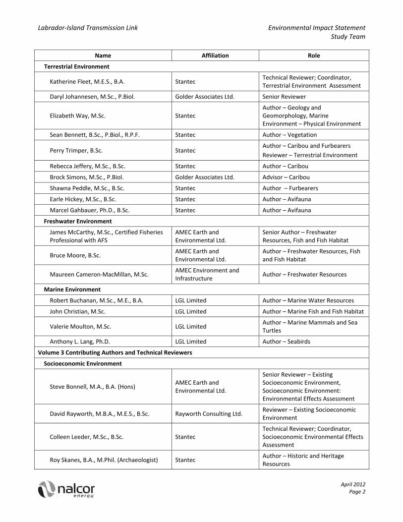
The Environmental Impact Statement (EIS) document was prepared by a team of environmental consultants working with personnel from Nalcor Energy.
Name Affiliation Role
Nalcor Energy Executive
Edmund J. Martin, M.B.A., B. Comm. Nalcor Energy President and Chief Executive Officer
Gilbert Bennett, P.Eng. Nalcor Energy Vice President Lower Churchill Project
Paul Harrington Nalcor Energy Project Director
The technical team responsible for completing the EIS included:
Name Affiliation Role
Nalcor Energy EIS Management Team
Stephen Pellerin, M.Eng., B.Sc. Nalcor Energy Environment and Aboriginal Affairs Manager
Jacquelyn Wells, M.Sc., B.Sc. (Hons), B.Ed. Nalcor Energy Labrador ‐ Island Transmission Link EIS Supervisor
Leah Fudge, B.Sc., Adv. Dip. Nalcor Energy EA Support (Lower Churchill Project ‐ Transmission)
Daryl Johannesen, M.Sc., P.Biol. Golder Associates Ltd. EIS Management Lead
Kim McFarlane, B.Sc., M.E.Des., P.Biol. Golder Associates Ltd. EIS Management Project Manager
Susanna Lin, B.Mgt. Golder Associates Ltd. EIS Management Project Coordinator
Volume 1 Contributing Authors and Technical Reviewers
Steve Bonnell, M.A., B.A. (Hons) Nalcor Energy
Author – Introduction, Project Rationale and Planning, Environmental Setting and Context, EA Approach and Methodology
Jacinta McNairn, M.Sc., P.Eng. Golder Associates Ltd.
Author – Project Description, Effects of the Environment on the Project, Accidents and Malfunctions, (Executive Summary, Plain Language Summary)
Kyle Tucker, M.Eng., P.Eng. Nalcor Energy Area Manager ‐ Overland Transmission, Technical Contributor and Reviewer
Gale Warren, M.A. Nalcor Energy Technical Contributor and Reviewer
Volume 2A and B Contributing Authors and Technical Reviewers
Atmospheric Environment
Michael C. Murphy, Ph.D., P.Eng. Stantec Author – Atmospheric Environment
John Walker, Ph.D. Stantec Author – Atmospheric Environment
Karen M. Gillam, M.Sc., B.A. Stantec Author – Atmospheric Environment
Labrador‐Island Transmission Link Environmental Impact Statement Study Team
April 2012 Page 2
Name Affiliation Role
Terrestrial Environment
Katherine Fleet, M.E.S., B.A. Stantec Technical Reviewer; Coordinator, Terrestrial Environment Assessment
Daryl Johannesen, M.Sc., P.Biol. Golder Associates Ltd. Senior Reviewer
Elizabeth Way, M.Sc. Stantec Author – Geology and Geomorphology, Marine Environment – Physical Environment
Sean Bennett, B.Sc., P.Biol., R.P.F. Stantec Author – Vegetation
Perry Trimper, B.Sc. Stantec Author – Caribou and Furbearers
Reviewer – Terrestrial Environment
Rebecca Jeffery, M.Sc., B.Sc. Stantec Author – Caribou
Brock Simons, M.Sc., P.Biol. Golder Associates Ltd. Advisor – Caribou
Shawna Peddle, M.Sc., B.Sc. Stantec Author – Furbearers
Earle Hickey, M.Sc., B.Sc. Stantec Author – Avifauna
Marcel Gahbauer, Ph.D., B.Sc. Stantec Author – Avifauna
Freshwater Environment
James McCarthy, M.Sc., Certified Fisheries Professional with AFS
AMEC Earth and Environmental Ltd.
Senior Author – Freshwater Resources, Fish and Fish Habitat
Bruce Moore, B.Sc. AMEC Earth and Environmental Ltd.
Author – Freshwater Resources, Fish and Fish Habitat
Maureen Cameron‐MacMillan, M.Sc. AMEC Environment and Infrastructure
Author – Freshwater Resources
Marine Environment
Robert Buchanan, M.Sc., M.E., B.A. LGL Limited Author – Marine Water Resources
John Christian, M.Sc. LGL Limited Author – Marine Fish and Fish Habitat
Valerie Moulton, M.Sc. LGL Limited Author – Marine Mammals and Sea Turtles
Anthony L. Lang, Ph.D. LGL Limited Author – Seabirds
Volume 3 Contributing Authors and Technical Reviewers
Socioeconomic Environment
Steve Bonnell, M.A., B.A. (Hons) AMEC Earth and Environmental Ltd.
Senior Reviewer – Existing Socioeconomic Environment, Socioeconomic Environment: Environmental Effects Assessment
David Rayworth, M.B.A., M.E.S., B.Sc. Rayworth Consulting Ltd. Reviewer – Existing Socioeconomic Environment
Colleen Leeder, M.Sc., B.Sc. Stantec Technical Reviewer; Coordinator, Socioeconomic Environmental Effects Assessment
Roy Skanes, B.A., M.Phil. (Archaeologist) Stantec Author – Historic and Heritage Resources

Labrador‐Island Transmission Link Environmental Impact Statement Study Team
April 2012 Page 3
Name Affiliation Role
Keith Storey, Ph.D., M.A., B.A. (Hons) Stantec Author – Communities; Economy, Employment and Business
Mark Shrimpton, M.A., B.A. (Hons) Stantec Author – Communities ; Economy, Employment and Business
Nancy Griffiths, B.DEP. AMEC Earth and Environmental Ltd.
Author – Land and Resource Use; Tourism
Strat Canning, B.Sc.F., D.T.R.P. Canning and Pitt Co‐Author – Marine Fisheries
Robert Pitt, M.A., B.Sc., B.A. Canning and Pitt Co‐Author – Marine Fisheries
Susan Sherk, B.A. AMEC Earth and Environmental Ltd.
Author – Tourism
Jim Floyd, L.Arch. Sikumiut Environmental Management Ltd.
Author – Visual Aesthetics (Existing Environment)
Andrea Rowe, B.A., B.E.D. (Land. Arch.) Sikumiut Environmental Management Ltd.
Author – Visual Aesthetics (Effects Assessment)
Kevin Graham, B.Sc. iSiteVisualization Advisor – Visual Aesthetics
Peter Thiede, Dipl. Ing. Golder Associates Ltd. Advisor – Visual Aesthetics
Nalcor Energy extends thanks to the technical team as well as the geomatics, word processing and editorial teams who worked on the EIS.
Nalcor Energy
April 2012

April 2012
NALCOR ENERGY
LABRADOR‐ISLAND TRANSMISSION LINK
ENVIRONMENTAL IMPACT STATEMENT
Chapter 1
Introduction
Labrador‐Island Transmission Link Environmental Impact Statement Chapter 1 Introduction
April 2012 Page i
TABLE OF CONTENTS
SECTION PAGE
1 INTRODUCTION.............................................................................................................................................. 1‐1 1.1 Nature and Overview of the Project ...................................................................................................... 1‐1 1.2 Identification of the Proponent ............................................................................................................. 1‐3 5 1.3 Environmental Assessment Processes and Requirements .................................................................... 1‐8 1.4 Previous and Other Environmental Assessments .................................................................................. 1‐9 1.5 Purpose and Organization of the EIS ................................................................................................... 1‐11 1.6 References ........................................................................................................................................... 1‐14
10
LIST OF FIGURES
Figure 1.1‐1 Labrador‐Island Transmission Link ...................................................................................... 1‐2 Figure 1.2‐1 Nalcor Energy Organizational Structure .............................................................................. 1‐5 Figure 1.2‐2 Existing Newfoundland and Labrador Generation and Transmission System .................... 1‐7 15

Labrador‐Island Transmission Link Environmental Impact Statement Chapter 1 Introduction
April 2012 Page ii
LIST OF ACRONYMS
Acronym Description
ac alternating current
CEA Agency Canadian Environmental Assessment Agency
CEAA Canadian Environmental Assessment Act
dc direct current
EA Environmental Assessment
EIS Environmental Impact Statement
GIS Geographic Information System
GNL Government of Newfoundland and Labrador
HVdc High Voltage direct current
Island Newfoundland
km kilometre
MW megawatt
NLEPA Newfoundland and Labrador Environmental Protection Act
NLH Newfoundland and Labrador Hydro
Project Labrador‐Island Transmission Link
SI System International
US United States
VEC Valued Environmental Component

Labrador‐Island Transmission Link Environmental Impact Statement Chapter 1 Introduction
April 2012 Page 1‐1
1 INTRODUCTION
Nalcor Energy (Nalcor) is proposing to develop the Labrador‐Island Transmission Link (Project), a High Voltage direct current (HVdc) transmission system extending from the lower Churchill River in Central Labrador to Soldiers Pond on the Island of Newfoundland’s (Island) Avalon Peninsula.
The Project is subject to environmental assessment (EA) review under the Newfoundland and Labrador 5 Environmental Protection Act (NLEPA) and the Canadian Environmental Assessment Act (CEAA). This Environmental Impact Statement (EIS) is being submitted by Nalcor, as Proponent, in accordance with the requirements of the provincial and federal EA processes and the associated Environmental Impact Statement Guidelines and Scoping Document issued by the provincial and federal governments in May 2011 (Government of Newfoundland and Labrador and Government of Canada 2011). 10
As an introduction to the EIS, this chapter provides a general overview of the proposed Project, identifies the Proponent, outlines the regulatory and policy contexts for the Project, and describes the purpose of the EIS and the overall organization of the document.
1.1 Nature and Overview of the Project
The proposed Project will involve the Construction, and Operations and Maintenance of transmission 15 infrastructure within and between Labrador and the Island of Newfoundland. The development of this Project is an important aspect of the Energy Plan that was released by the Government of Newfoundland and Labrador (GNL) in September 2007 (GNL 2007).
The proposed Project will extend over a distance of approximately 1,100 kilometres (km), and include the following key components (Figure 1.1‐1): 20
an alternating current to direct current (ac to dc) converter station at Muskrat Falls near the lower Churchill River in Central Labrador;
an overhead transmission line from Muskrat Falls to the Strait of Belle Isle (approximately 400 km);
marine cable crossings of the Strait of Belle Isle with associated infrastructure;
an overhead transmission line from the Strait of Belle Isle to Soldiers Pond on the Island’s Avalon Peninsula 25 (approximately 700 km);
a dc to ac converter station at Soldiers Pond, with some associated Island system upgrades; and
electrodes, or high capacity grounding systems, in the Strait of Belle Isle (Labrador) and Conception Bay (Newfoundland), connected to their respective converter stations by small overhead transmission lines.
Commencing in 2011 with detailed engineering and conditional on release from environmental assessment in 30 2012, the current schedule would see construction, including procurement activities, begin in 2012 and conclude in 2016, followed by Project commissioning and operations.
The Project is being proposed and designed based on the concept and principles of sustainable development ‐ which has guided and formed the basis of the Project’s overall purpose and rationale, as well as its ongoing planning, as outlined below and throughout this EIS. 35
The Project is an important part of ongoing efforts towards securing an adequate, reliable and clean electricity supply to address the province’s current and future energy needs. It will facilitate the transmission of electricity from the proposed Lower Churchill Hydroelectric Generation Project in Central Labrador to the Island, that will then be distributed through the existing Island grid throughout Newfoundland. This will allow the displacement of existing generation from the Holyrood Thermal Generating Station in eastern 40 Newfoundland, to address the air quality issues currently associated with that facility’s emissions, as well as providing additional energy to address projected future requirements and facilitate further economic development.

!
!
!
!
!
!
!
!
!
!
!
!
!
!
!!
!
!
!
"S
"S
G u l fo f
S t . L a w r e n c e
L a b r a d o r S e a
A t l a n t i c O c e a nSt r a
i t of B
e l l e I s l e
Red Bay
Forteau
Marystown
Deer Lake
Cartwright
Clarenville
Mary's Harbour
North West River
Port Hope Simpson
Happy Valley-Goose Bay
Channel-Port aux Basques
Nain
St. John's
Corner Brook
Churchill Falls
St. Anthony
GanderGrand Falls-Windsor
Labrador City / Wabush
0 100 200
Kilometres
FIGURE 1.1-1
Labrador - Island Transmission Link
FIGURE ID: HVDC_ST_486
±
"S Converter Station
Transmission Corridor
Submarine Cable Crossing Corridor
Muskrat Falls
C A N A D A
SoldiersPond

Labrador‐Island Transmission Link Environmental Impact Statement Chapter 1 Introduction
April 2012 Page 1‐3
The transmission of clean, renewable hydroelectricity from Labrador to the Island through the Project is the most environmentally, technically and economically preferred option for meeting the Island’s current and future energy needs. This is discussed further in Chapter 2 of this EIS.
Nalcor is encouraged by the environmental and socioeconomic benefits that will be realized through this Project, and is confident that any environmental issues that may be associated with the Project can be 5 addressed through sound Project planning and implementation. As illustrated throughout this EIS, the EA process, including its associated governmental, Aboriginal and stakeholder consultation, has been and will continue to be a key aspect of Project planning and design.
A full discussion of the purpose of and rationale for the Project – including its environmental and socioeconomic benefits and overall relationship to the principles of sustainable development – is provided in 10 Chapter 2 and a detailed Project description is included in Chapter 3.
1.2 Identification of the Proponent
Newfoundland and Labrador has an immense and diverse energy warehouse. Guided by a long‐term Energy Plan (GNL 2007) to manage these energy resources, in 2008 the Government of Newfoundland and Labrador created Nalcor Energy, a new provincial Crown corporation. Nalcor is the proponent for the Labrador‐Island 15 Transmission Link.
Name of Corporate Body: Nalcor Energy
Address: Hydro Place, 500 Columbus Drive P.O. Box 12800 St. John’s, Newfoundland and Labrador Canada A1B 4K7
Tel. (709) 737‐1833, Toll Free 1‐888‐576‐5454 (within Canada) Fax. (709) 737‐1985 Email. [email protected]
President and Chief Executive Officer: Edmund J. Martin
Principal Contact Persons for the Purposes of Environmental Assessment:
Stephen Pellerin Manager, Environmental and Aboriginal Affairs Tel. (709) 737‐4218, Toll Free 1‐888‐576‐5454 (within Canada) Email. [email protected]
Gilbert Bennett Vice President, Lower Churchill Project Tel. (709) 737‐1836, Toll Free 1‐888‐576‐5454 (within Canada) Email. [email protected]
Nalcor’s foundation is built on its core business – the generation and transmission of electrical power – and the corporation has a strong commitment to providing safe, reliable and dependable electricity to its utility, industrial, residential and retail customers. Beyond that core business, the corporation’s focus has expanded 20 into the broader energy sector, including oil and gas, wind energy, and research and development.

Labrador‐Island Transmission Link Environmental Impact Statement Chapter 1 Introduction
April 2012 Page 1‐4
The Newfoundland and Labrador Energy Corporation Act authorizes Nalcor to invest in, engage in and carry out activities in the energy sector within Newfoundland and Labrador (and, with approval, outside the province), including:
the development, generation, production, transmission, distribution, delivery, supply, sale, export, purchase and use of energy from wind, water, steam, gas, coal, oil, hydrogen or other products used in 5 power production;
exploration for development, production, refining, marketing and transportation of hydrocarbons and products made from hydrocarbons;
manufacturing, production, distribution and sale of energy‐related products and services; and
research and development. 10
Nalcor’s vision is to build a strong economic future for successive generations of Newfoundlanders and Labradorians. As a proud, diverse energy company, its people are committed to a bright future for the province, united by the following goals and core values:
Goals
Safety: To be a world class safety leader 15
Environment: To be an environmental leader
Business Excellence: Through operational excellence to provide exceptional value to all consumers of our energy
People: To ensure a highly‐skilled and motivated team of employees who are strongly committed to our success and future direction 20
Community: To be a valued corporate citizen in Newfoundland and Labrador
Core Values
Open Communication: Fostering an environment where information moves freely in a timely manner
Accountability: Holding ourselves responsible for our actions and performance
Safety: Relentless commitment to protecting ourselves, our colleagues and our community 25
Honesty and Trust: Being sincere in everything we say and do
Teamwork: Sharing our ideas in an open and supportive manner to achieve excellence
Respect and Dignity: Appreciating the individuality of others by our words and actions
Leadership: Empowering individuals to help guide and inspire others
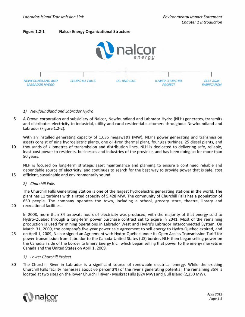
Nalcor is leading the development of the province’s energy resources, and is focused on environmentally 30 responsible and sustainable growth. The corporation currently has five lines of business (Figure 1.2‐1):
Labrador‐Island Transmission Link Environmental Impact Statement Chapter 1 Introduction
April 2012 Page 1‐5
Figure 1.2‐1 Nalcor Energy Organizational Structure
1) Newfoundland and Labrador Hydro
A Crown corporation and subsidiary of Nalcor, Newfoundland and Labrador Hydro (NLH) generates, transmits 5 and distributes electricity to industrial, utility and rural residential customers throughout Newfoundland and Labrador (Figure 1.2‐2).
With an installed generating capacity of 1,635 megawatts (MW), NLH’s power generating and transmission assets consist of nine hydroelectric plants, one oil‐fired thermal plant, four gas turbines, 25 diesel plants, and thousands of kilometres of transmission and distribution lines. NLH is dedicated to delivering safe, reliable, 10 least‐cost power to residents, businesses and industries of the province, and has been doing so for more than 50 years.
NLH is focused on long‐term strategic asset maintenance and planning to ensure a continued reliable and dependable source of electricity, and continues to search for the best way to provide power that is safe, cost efficient, sustainable and environmentally sound. 15
2) Churchill Falls
The Churchill Falls Generating Station is one of the largest hydroelectric generating stations in the world. The plant has 11 turbines with a rated capacity of 5,428 MW. The community of Churchill Falls has a population of 650 people. The company operates the town, including a school, grocery store, theatre, library and recreational facilities. 20
In 2008, more than 34 terawatt hours of electricity was produced, with the majority of that energy sold to Hydro‐Québec through a long‐term power purchase contract set to expire in 2041. Most of the remaining production is used for mining operations in Labrador West and Hydro's Labrador Interconnected System. On March 31, 2009, the company's five‐year power sale agreement to sell energy to Hydro‐Québec expired, and on April 1, 2009, Nalcor signed an Agreement with Hydro‐Québec under its Open Access Transmission Tariff for 25 power transmission from Labrador to the Canada‐United States (US) border. NLH then began selling power on the Canadian side of the border to Emera Energy Inc., which began selling that power to the energy markets in Canada and the United States on April 1, 2009.
3) Lower Churchill Project
The Churchill River in Labrador is a significant source of renewable electrical energy. While the existing 30 Churchill Falls facility harnesses about 65 percent(%) of the river’s generating potential, the remaining 35% is located at two sites on the lower Churchill River ‐ Muskrat Falls (824 MW) and Gull Island (2,250 MW).

Labrador‐Island Transmission Link Environmental Impact Statement Chapter 1 Introduction
April 2012 Page 1‐6
The proposed Lower Churchill Project is one of the best undeveloped hydro resources in North America. It is one of the key elements in the province's energy warehouse, and provides an opportunity for Newfoundland and Labrador to meet its own energy needs in an environmentally‐sustainable way, with enough power remaining to export to other jurisdictions where the demand for clean energy is growing. Nalcor is actively working towards the development of the Lower Churchill Project. 5
This business unit of Nalcor also has overall responsibility for the planning and development of the Labrador‐Island Transmission Link.
4) Oil and Gas
Nalcor Energy – Oil and Gas holds and manages oil and gas interests in Newfoundland and Labrador onshore and offshore. The company is currently a partner in three offshore developments ‐ the Hebron Oil Field, the 10 White Rose Growth Project and the Hibernia Southern Extension.
Nalcor Energy ‐ Oil and Gas continues to assess growth opportunities for the province's oil and gas resources. Committed to marketing these opportunities around the world, Nalcor Energy – Oil and Gas will maximize benefits from these resources to help attract continued investment that will strengthen the economy in Newfoundland and Labrador. 15
5) Bull Arm Fabrication
The Bull Arm facility is Atlantic Canada's largest industrial fabrication site, and is strategically located in Newfoundland and Labrador near St. John's, close to international shipping lanes and centrally positioned to service major developments worldwide. The facility has fully integrated and comprehensive infrastructure to support fabrication and assembly of three key project functions, simultaneously, in three separate theatres: 20 Topsides Fabrication and Assembly; Drydock Fabrication and Construction; and a Deepwater Site. This world‐class facility is located close to the communities of Sunnyside, Arnold's Cove and Come By Chance and has provided employment and economic spin‐off benefits, as well as broader benefits to the province through new infrastructure, technical knowledge and expertise, technology transfer and an experienced labour force.
The Bull Arm facility is an important asset in the development and advancement of the province’s oil and gas 25 industry and fabrication capacity, and the transfer of the site to be operated as a subsidiary of Nalcor ensures it is utilized to maximize the benefits to the province from the number of large‐scale construction and fabrication projects on the horizon ‐ locally and around the world.
Additional information on Nalcor, including its overall organization, values, priorities and activities, can be found at: www.nalcorenergy.com. 30
As reflected in its above‐listed corporate goals and values, Nalcor strives to be a leader in environmental protection and sustainability, and is committed to maintaining a high standard of environmental responsibility and performance. Through its NLH and Churchill Falls subsidiaries, Nalcor has constructed and currently operates an extensive electricity transmission system throughout Newfoundland and Labrador. This includes interconnected electrical power systems on the Island and in Labrador, as well as isolated distribution systems 35 throughout rural areas of the province.
Environmental protection planning is an integral part of Nalcor’s planning, Construction, and Operations and Maintenance programs. The corporation has state‐of‐the‐art and proven policies and procedures related to environmental protection and management which will be implemented throughout this Project. Nalcor has an outstanding record of environmental protection and stewardship, and this objective and experience will be 40 applied to the planning and development of this Project to avoid or reduce potential environmental effects during its Construction, and Operations and Maintenance phases.
A detailed overview of Nalcor’s policies, plans, management systems and other initiatives that are relevant to the Project, and in particular, to addressing environmental issues and associated consultation, is provided throughout the EIS. 45

Labrador‐Island Transmission Link Environmental Impact Statement Chapter 1 Introduction
April 2012 Page 1‐7
Figure 1.2‐2 Existing Newfoundland and Labrador Generation and Transmission System

Labrador‐Island Transmission Link Environmental Impact Statement Chapter 1 Introduction
April 2012 Page 1‐8
1.3 Environmental Assessment Processes and Requirements
Environmental Assessment (EA) is a regulatory review process that is often applied to proposed developments to proactively identify and seek to address potential environmental effects in project planning and decision‐making. Through EA review, environmental issues are identified (often through consultation), likely environmental effects are assessed and evaluated, and measures to avoid or reduce adverse effects and 5 optimize benefits are identified and proposed. The results of an EA are considered in project design, and ultimately, in eventual government (regulatory) decisions regarding whether and how the Project can proceed.
In Newfoundland and Labrador, proposed development projects may be subject to provincial and / or federal EA requirements.
The NLEPA requires anyone who plans a project that could have a significant effect on the natural, social or 10 economic environment (an “Undertaking”) to present it for examination through the provincial EA process. Under the NLEPA, this Project is considered an Undertaking subject to Part X, and pursuant to Section 34(2) of the associated Environmental Assessment Regulations:
34. (2) An undertaking that will be engaged in the construction of new electric power transmission lines or the relocation or realignment of existing lines where a portion of a new line 15 will be located more than 500 metres from an existing right of way shall be registered.
The federal EA process under the CEAA and its associated regulations applies to projects that involve the federal government ‐ as proponent, regulator, and / or as a source of funding or land. A number of federal departments and agencies have potential decision‐making responsibilities in relation to this Project, which have triggered the requirement for a federal EA as outlined below. 20
On January 29, 2009, Nalcor submitted the Labrador‐Island Transmission Link Environmental Assessment Registration and Project Description (Nalcor 2009a) to the provincial and federal governments, to formally initiate the provincial and federal EA processes for the Project.
Following governmental and public review of that EA Registration, on March 23, 2009, the provincial Minister of Environment and Conservation announced that an EIS was required for the Project. 25
On April 2, 2009, an EA Committee comprised of representatives of various applicable provincial and federal government departments was appointed.
On September 15, 2009, Nalcor submitted a revision and update to the initial (January 2009) EA Registration and Project Description to the provincial and federal governments (Nalcor 2009b). That submission specified that the previously included transmission corridor option within Gros Morne National Park in western 30 Newfoundland was no longer being considered, and that the Long Range Mountains crossing alternative was now the proposed transmission corridor for the Project and its EA (Chapter 3).
On November 26, 2009 (subsequently updated on July 19, 2010), the Canadian Environmental Assessment Agency (CEA Agency) issued a “Notice of Commencement” for the federal EA for the Project, indicating that several federal departments were required to ensure that a Comprehensive Study was conducted in relation 35 to the development proposal. Specifically, under Section 5 of the CEAA, an EA is required because, for the purpose of enabling the Project to be carried out in whole or in part:
Environment Canada may take action in relation to Subsection 127(1) of the Canadian Environmental Protection Act;
Fisheries and Oceans Canada may take action in relation to Subsection 35(2) of the Fisheries Act; and 40
Transport Canada may take action in relation to Section 5 of the Navigable Waters Protection Act.

Labrador‐Island Transmission Link Environmental Impact Statement Chapter 1 Introduction
April 2012 Page 1‐9
The CEA Agency has been identified as the Federal EA Coordinator for the CEAA assessment. The Project has been identified as a major natural resource project, and therefore falls under the federal Major Projects Management Office's process to track and monitor the progress of such projects through the federal regulatory system.
On November 15, 2010, Nalcor submitted a Project description update to the provincial and federal 5 governments, which indicated that it was no longer proposing to place sea electrodes in Lake Melville or Holyrood Bay ‐ as was reflected in the initial EA Registration and Project Description (Nalcor 2009a, b) ‐ nor to develop the associated wood‐pole line connections to these sites. Rather, the Project concept would see the use of shore electrodes at locations in the Strait of Belle Isle area (Labrador side) and Conception Bay South (Newfoundland). Through that submission, Nalcor also advised that it would also be assessing the option of 10 locating the Project's Labrador converter station at or near the Muskrat Falls site on the lower Churchill River and an associated transmission line corridor from that location.
On February 7, 2011, following earlier review by Aboriginal communities and organizations, the provincial and federal governments issued Draft EIS Guidelines and Scoping Document for public review and comment.
On April 14, 2011, Nalcor submitted a further update to the Project description under the EA process, which 15 indicated that in addition to the originally identified cable landing sites and two marine cable corridors in the Strait of Belle Isle, it would also be assessing a potential option that would see a single cable corridor between Forteau Point (Labrador) and Shoal Cove (Newfoundland).
On May 3, 2011, the Final EIS Guidelines and Scoping Document were approved by the Ministers and issued to Nalcor to guide its preparation of this EIS. 20
From May 2011, to the present, Nalcor Energy has submitted various Environmental Component Studies under the EA process for review and comment by government departments and agencies, Aboriginal and stakeholder groups and the public.
In addition to approvals under the provincial and federal EA processes, the Project will require various other provincial, federal and municipal authorizations. There are a number of other policies, legislation and 25 regulations which apply to the Project and its environmental management and planning that have been considered and incorporated directly and integrally into Project planning and design, and are identified and discussed in detail later in the EIS (Chapters 2, 3 and 6). A discussion of Aboriginal communities and organizations and any associated land claims or other agreements which are relevant to the Project and its EA is provided in Chapters 6, 7, 15 and 16. 30
1.4 Previous and Other Environmental Assessments
The current planning, engineering and environmental work for the Project is building on previous studies related to the transmission of electricity between Labrador and the Island that began over 30 years ago. Although the current Project proposal has been defined and initiated under the direction of the Energy Plan released by the Government of Newfoundland and Labrador in September 2007, the concept of such a 35 transmission link has been the subject of consideration and analysis over several decades, including a number of previous development attempts and EAs.
In the mid‐1970s, in advance of the formal establishment of federal and provincial EA processes, a federal‐provincial Review Panel was appointed to coordinate an EA review. That process eventually involved the completion and submission of separate EA Reports for the Transmission Link and for the Lower Churchill 40 Hydroelectric Generation Facilities at Gull Island and Muskrat Falls, followed by public hearings and an eventual Panel Report and associated government decisions.

Labrador‐Island Transmission Link Environmental Impact Statement Chapter 1 Introduction
April 2012 Page 1‐10
With regard to the Project in particular, the following summarizes the key stages of this previous EA review:
NLH completed and submitted a Transmission Line Project Description and Environmental Policy Statement (EIS) to the EA Panel in July 1978.
Following review by the Panel, relevant government agencies and the public, a Deficiency Statement was issued to the Proponent in March 1979. In 1979 and 1980, a series of environmental studies were 5 conducted and submitted in support of a Transmission Line EIS Addendum.
In 1979, a public consultation program was initiated by the proponent which included the establishment of a Liaison Committee in Central Labrador, and public meetings in St. John’s, Grand Falls, Daniel’s Harbour, Flower’s Cove, Forteau, West St. Modeste, Mud Lake, North West River and Happy Valley‐Goose Bay.
In December 1979, a Transmission Line EIS Addendum was submitted to the Panel. In June 1980, the Panel 10 issued the results of the review of the Addendum, which the proponent responded to with further information.
EA Panel Hearings were held in relation to the Transmission Link and the Lower Churchill Hydroelectric Generation Project in September 1980, which included public meetings in St. John’s, Flower’s Cove, Forteau, West St. Modeste, Sheshatshiu, North West River and Happy Valley‐Goose Bay. 15
The proponent subsequently prepared and submitted a Supplemental Brief in September 1980 to address outstanding issues that were raised at the Hearings.
On December 11, 1980, the federal Minister of Environment released and endorsed the report of the EA Panel, which concluded that the Transmission Link and the Lower Churchill Hydroelectric Generation Projects were environmentally acceptable, provided that certain environmental and socioeconomic 20 measures were implemented.
Some initial construction work on the Transmission Link was carried out, particularly in the Strait of Belle Isle area, but the project was not completed for economic reasons.
Subsequently, in November 1990, NLH prepared and submitted an EA Registration for the transmission and generation developments under the then Newfoundland Environmental Assessment Act. The province 25 subsequently determined that an EIS would be required and issued EIS Guidelines in May 1991. The EA process did not progress beyond that point, as failure to reach agreement on access to external markets resulted in suspension of this development effort.
In the late 1990s, the Labrador Hydro Project Office was established to plan and develop the Churchill River Power Project, which for a period included the transmission link project. A number of associated 30 environmental baseline studies were undertaken in 1998.
As a result of these previous EA activities and development efforts, there exists an extensive body of knowledge about the Project, the natural and human environments through which it will extend, and the key questions and issues related to the Project and its potential interactions with the environment. This information and understanding has been, and will continue to be, invaluable in ongoing Project planning and 35 design.
In terms of other ongoing and possible future EAs, as noted above, the proposed Project is intended to transmit a portion of the energy output from the proposed Lower Churchill Hydroelectric Generation Project in Central Labrador to the Island. The EA of that project, including the Muskrat Falls and Gull Island generation facilities and transmission interconnections between them and Churchill Falls, was initiated in December 2006 40 with Joint Review Panel hearings taking place March to April 2011 and a JRP Report released in August 2011.

Labrador‐Island Transmission Link Environmental Impact Statement Chapter 1 Introduction
April 2012 Page 1‐11
A key rationale for the proposed Project is to provide energy and infrastructure for further development and growth in Newfoundland and Labrador’s energy sector and overall economy. This could result in future proposals pertaining to, for example:
new industrial developments (energy consumers) in the province that may utilize the electricity transmitted by the Project; 5
new energy generation facilities within the province that utilize the transmission infrastructure / interconnection provided by the Project; and / or
future transmission infrastructure for energy distribution within the province and / or export, which may be made necessary and viable as a result of the Project and / or the above developments.
Any such future development projects and / or transmission infrastructure which may be associated with such 10 power use, distribution and / or export would be presented for EA review by the relevant proponent(s) of those project(s), once they are determined and defined. In November 2010, Nalcor announced that a term sheet with Emera Inc. of Nova Scotia had been signed. The term sheet contemplates arrangements leading to the construction of a transmission link between the Island and Nova Scotia (the Maritime Link). These arrangements have not been finalized, and the construction of the Project is not dependent on construction of 15 the Maritime Link. With or without the Maritime Link, the Project is the preferred alternative to meet Newfoundland’s electricity needs.
1.5 Purpose and Organization of the EIS
This EIS has been developed and is being submitted by Nalcor, as the Proponent of the Project, in accordance with the provisions and requirements of the provincial and federal EA legislation and regulations, as well as the 20 associated final EIS Guidelines and Scoping Document (Government of Newfoundland and Labrador and the Government of Canada 2011).
The submission of the EIS is an important step in the EA review process for this Project. It provides the required information on the Project and its potential environmental and socioeconomic outcomes, including the: 25
Project purpose, rationale and planning;
Project description (components and Construction, and Operations and Maintenance activities);
existing biophysical and socioeconomic environments;
consultation activities, and the various questions and issues identified;
likely environmental effects of the Project; 30
proposed measures to avoid or reduce adverse effects and enhance benefits; and
plans for environmental monitoring and follow‐up during Project Construction, and Operations and Maintenance.
The EIS will form the basis for further review, consideration and discussion of the Project and these items by governments, Aboriginal and stakeholder groups, the interested public and Nalcor as part of the EA review 35 process. Based on the results of the EA and the associated reviews and input, the provincial and federal Ministers will decide whether the Project can proceed, and if so, under what terms and conditions.
The EIS has been prepared and structured to provide the results of the EA and other required information in a clear, concise and well‐organized manner, in keeping with current EA practice and with a view to overall readability and utility for all of its likely readers. This includes relevant government departments and agencies, 40 Aboriginal and stakeholder organizations and the general public.

Labrador‐Island Transmission Link Environmental Impact Statement Chapter 1 Introduction
April 2012 Page 1‐12
The EIS document is structured as follows:
Chapter 1 (this Introduction): Provides a general overview of the Project, identifies the Proponent, outlines the regulatory and policy contexts for the Project, and describes the purpose of the EIS and the overall organization of the document.
Chapter 2 (Project Rationale and Planning): Sets the overall context for the Project by discussing the 5 following: overall need, purpose and rationale; alternatives to the Project; previous and ongoing Project planning and design activities, including those that led to the current design concept; alternative means of carrying out the Project, including an overall evaluation of technical and economic feasibility and the identification of those options that are subject to detailed environmental analysis; and a description of future (post‐EA) Project design activities, including detailed route selection the eventual selection of a specific route 10 for the transmission line. It also provides an overview of various policies, plans and other procedures and initiatives that are relevant to the Project, and in particular, to avoiding or managing potential environmental effects.
Chapter 3 (Project Description): Provides an overview and detailed description of the Project, including its location, key components and overall layout, Construction, and Operations and Maintenance activities and 15 events, labour force requirements, Project expenditures and schedule.
Chapter 4 (Effects of the Environment on the Project): Discusses how the existing biophysical and socioeconomic environments have and may affect the Project, including the manner in which environmental conditions and factors have and will influence Project design, and potential associated events and effects which may occur during Project construction and / or operations. 20
Chapter 5 (Accidents and Malfunctions): Discusses accidental events and malfunctions that could potentially occur during all phases of the Project, as well as where and how these are considered and addressed in the EA.
Chapter 6 (Environmental Setting and Context): Gives a general and high‐level overview of the existing natural and human environments, as background and context for the Project and its EA.
Chapter 7 (Aboriginal Consultation and Issues Scoping): Describes Nalcor’s previous and ongoing consultation 25 efforts and initiatives with Aboriginal communities and organizations relevant to the Project and its EA, and identifies the questions, issues and concerns raised regarding the Project and its potential effects, and where and how these are addressed in the EIS.
Chapter 8 (Regulatory, Stakeholder and Public Consultation and Issues Scoping): Describes Nalcor’s previous and ongoing regulatory, stakeholder and public consultation programs and activities relevant to the Project 30 and its EA, and identifies the questions, issues and concerns raised regarding the Project and its potential effects, and where and how these are addressed in the EIS.
Chapter 9 (EA Approach and Methods): Describes the overall approach and methods used to conduct the Project’s EA, including each of its key stages.
Chapter 10 (Existing Biophysical Environment): Provides a description of the existing natural environment that 35 overlaps and may interact with the proposed Project, including its atmospheric, terrestrial, freshwater and marine components (i.e., the baseline).
Chapter 11 (Atmospheric Environment – Environmental Effects Analysis): Provides the detailed results of the environmental effects assessment for the Atmospheric Environment, including each of the selected Valued Environmental Components (VECs), using the EA approach and methods described in Chapter 9. 40
Chapter 12 (Terrestrial Environment – Environmental Effects Analysis): Provides the detailed results of the environmental effects assessment for the Terrestrial Environment, including each of the selected VECs, using the EA approach and methods described in Chapter 9.

Labrador‐Island Transmission Link Environmental Impact Statement Chapter 1 Introduction
April 2012 Page 1‐13
Chapter 13 (Freshwater Environment – Environmental Effects Analysis): Provides the detailed results of the environmental effects assessment for the Freshwater Environment, including each of the selected VECs, using the EA approach and methods described in Chapter 9.
Chapter 14 (Marine Environment – Environmental Effects Analysis): Provides the detailed results of the environmental effects assessment for the Marine Environment, including each of the selected VECs, using the 5 EA approach and methods described in Chapter 9.
Chapter 15 (Existing Socioeconomic Environment): Provides a description of the existing human environment that overlaps and may interact with the proposed Project, including each of its associated and relevant components.
Chapter 16 (Socioeconomic Environment – Environmental Effects Analysis): Provides the detailed results of 10 the environmental effects assessment for the Socioeconomic Environment, including each of the selected VECs, using the EA approach and methods described in Chapter 9.
Chapter 17 (Summary and Conclusions): Provides a summary of the key results and conclusions of the EIS, including: a summary of the Project; the purpose of the Project; a summary of the key environmental, social and economic benefits that will result from the Project; a summary of the commitments Nalcor has made for 15 this Project; a summary of the residual effects of the Project on the VECs and their significance; a description of the “with Project” environment, namely, an overview of the natural and socioeconomic environments with the Project and its effects; a summary of the post‐EIS environmental monitoring and follow‐up programs to be implemented if the Project proceeds; and, the overall conclusion of the EIS.
The figures presented in the EIS use a standard Geographic Information System (GIS) mapping (digital) format 20 with maps geo‐referenced. The GIS and all associated reports and studies use System International (SI) units of measure and terminology throughout.
Labrador‐Island Transmission Link Environmental Impact Statement Chapter 1 Introduction
April 2012 Page 1‐14
1.6 References
GNL (Government of Newfoundland and Labrador). 2007. Focusing Our Energy: Newfoundland and Labrador Energy Plan. Government of Newfoundland and Labrador, September 2007.
Government of Newfoundland and Labrador and Government of Canada. 2011. Environmental Impact Statement Guidelines and Scoping Document, Labrador‐Island Transmission Link. Prepared for Nalcor 5 Energy. St. John’s, NL.
Nalcor (Nalcor Energy). 2009a. Labrador – Island Transmission Link: Environmental Assessment Registration Pursuant to the Newfoundland and Labrador Environmental Protection Act, Project Description Pursuant to the Canadian Environmental Assessment Act. Submitted by Nalcor Energy: January 29, 2009. St. John’s, NL. 10
Nalcor. 2009b. Labrador – Island Transmission Link: Environmental Assessment Registration Pursuant to the Newfoundland and Labrador Environmental Protection Act, Project Description Pursuant to the Canadian Environmental Assessment Act. Revised September 15, 2009. St. John’s, NL.
April 2012
NALCOR ENERGY
LABRADOR‐ISLAND TRANSMISSION LINK
ENVIRONMENTAL IMPACT STATEMENT
Chapter 2
Project Rationale and Planning

Labrador‐Island Transmission Link Environmental Impact Statement Chapter 2 Project Rationale and Planning
April 2012 Page i
TABLE OF CONTENTS
SECTION PAGE
2 PROJECT RATIONALE AND PLANNING ........................................................................................................... 2‐1 2.1 Energy Plan ............................................................................................................................................ 2‐2 2.2 Need, Purpose and Rationale ................................................................................................................ 2‐2 5 2.3 Project Justification in Energy Terms .................................................................................................... 2‐3
2.3.1 Long‐Term Forecasting............................................................................................................... 2‐4 2.3.1.1 Current Environment ........................................................................................................ 2‐4 2.3.1.2 Historical Load Growth ..................................................................................................... 2‐5 2.3.1.3 Forecasting Methodology ................................................................................................. 2‐8 10 2.3.1.4 Key Forecast Assumptions and Drivers ........................................................................... 2‐10 2.3.1.5 2010 Planning Load Forecast Load Growth .................................................................... 2‐13
2.3.2 Generation Planning Criteria.................................................................................................... 2‐14 2.3.3 Transmission Planning Criteria ................................................................................................. 2‐15 2.3.4 System Capability ..................................................................................................................... 2‐16 15
2.3.4.1 Island Grid Generation .................................................................................................... 2‐16 2.3.4.2 Island Grid Transmission ................................................................................................. 2‐19
2.3.5 Transmission Reliability ............................................................................................................ 2‐19 2.3.5.1 Reliability Assessment ..................................................................................................... 2‐19 2.3.5.2 Transmission Reliability Summary .................................................................................. 2‐23 20
2.3.6 Identification of Need for Transmission .................................................................................. 2‐23 2.3.7 System Capability versus Load Forecast .................................................................................. 2‐23 2.3.8 Justification in Energy Terms ‐ Summary ................................................................................. 2‐24
2.4 Economic Analysis of the Project ........................................................................................................ 2‐25 2.4.1 Economic Evaluation Methodology ......................................................................................... 2‐25 25
2.4.1.1 Key Inputs to the Strategist® Cumulative Present Worth Analysis ................................ 2‐26 2.4.2 Thresholds for Economic Viability ............................................................................................ 2‐34
2.5 Alternative Generation Sources .......................................................................................................... 2‐35 2.5.1 Nuclear ..................................................................................................................................... 2‐36 2.5.2 Natural Gas ............................................................................................................................... 2‐37 30 2.5.3 Liquefied Natural Gas ............................................................................................................... 2‐38 2.5.4 Coal........................................................................................................................................... 2‐39 2.5.5 Continued Use of the Holyrood Thermal Generating Station .................................................. 2‐40 2.5.6 Simple Cycle Combustion Turbines .......................................................................................... 2‐42 2.5.7 Combined Cycle Combustion Turbines .................................................................................... 2‐43 35 2.5.8 Wind ......................................................................................................................................... 2‐44 2.5.9 Biomass .................................................................................................................................... 2‐46 2.5.10 Solar Energy ............................................................................................................................. 2‐48 2.5.11 Wave and Tidal Energy ............................................................................................................. 2‐50 2.5.12 Hydroelectric Generation ......................................................................................................... 2‐52 40
2.5.12.1 Island Pond ...................................................................................................................... 2‐54 2.5.12.2 Portland Creek ................................................................................................................ 2‐55 2.5.12.3 Round Pond ..................................................................................................................... 2‐56 2.5.12.4 Other Small Hydro ........................................................................................................... 2‐56
2.5.13 Labrador Hydroelectric Resources ........................................................................................... 2‐58 45 2.5.13.1 Deferred Churchill Falls ................................................................................................... 2‐58

Labrador‐Island Transmission Link Environmental Impact Statement Chapter 2 Project Rationale and Planning
April 2012 Page ii
2.5.13.2 Recall Power from Churchill Falls .................................................................................... 2‐59 2.5.13.3 Gull Island........................................................................................................................ 2‐59 2.5.13.4 Muskrat Falls ................................................................................................................... 2‐61
2.5.14 Regional Imports ...................................................................................................................... 2‐62 2.5.14.1 Price Volatility ................................................................................................................. 2‐63 5 2.5.14.2 Security of Supply ........................................................................................................... 2‐64 2.5.14.3 Potential Market Structural and Transmission Impediments ......................................... 2‐65
2.5.15 Summary of Supply Alternatives .............................................................................................. 2‐65 2.6 Development of Least‐Cost Generation Expansion Plans ................................................................... 2‐66
2.6.1 Isolated Island (No Project) Alternative ................................................................................... 2‐66 10 2.6.1.1 Isolated Island Transmission ........................................................................................... 2‐68 2.6.1.2 Isolated Island Cumulative Present Worth ..................................................................... 2‐69 2.6.1.3 Holyrood Plant Pollution Abatement and Life Extension ............................................... 2‐70
2.6.2 Interconnected Island (Project) Alternative ............................................................................. 2‐72 2.6.2.1 Interconnected Island Transmission ............................................................................... 2‐75 15 2.6.2.2 Interconnected Island Cumulative Present Worth ......................................................... 2‐76 2.6.2.3 Interconnected Island Summary ..................................................................................... 2‐77
2.7 Discussion of Economic Analysis ......................................................................................................... 2‐77 2.7.1 Sensitivity Analysis ................................................................................................................... 2‐78
2.7.1.1 Fuel Costs and Carbon Pricing ......................................................................................... 2‐78 20 2.7.1.2 Capital Costs .................................................................................................................... 2‐79 2.7.1.3 Load Forecasting and Conservation and Demand Management ................................... 2‐79 2.7.1.4 Churchill Falls Deferred Link ........................................................................................... 2‐80 2.7.1.5 Other Cumulative Present Worth Sensitivities ............................................................... 2‐81 2.7.1.6 Sensitivity Analysis Summary .......................................................................................... 2‐81 25
2.8 Financial Benefits ................................................................................................................................. 2‐81 2.8.1 Wholesale Rates ....................................................................................................................... 2‐82 2.8.2 Retail Rates .............................................................................................................................. 2‐85 2.8.3 Summary .................................................................................................................................. 2‐85
2.9 Environmental Benefits of the Project ................................................................................................ 2‐86 30 2.10 Risks and Risk Management ................................................................................................................ 2‐87
2.10.1.1 Risk Management Approach and Methodology ............................................................. 2‐90 2.10.1.2 Risk Management Philosophy ......................................................................................... 2‐90 2.10.1.3 Gateway Process ............................................................................................................. 2‐90 2.10.1.4 Project Specific Risks ....................................................................................................... 2‐91 35 2.10.1.5 Summary of Risk Management for the Project .............................................................. 2‐94
2.11 Project Planning ................................................................................................................................... 2‐94 2.11.1 Transmission Study Area Selection .......................................................................................... 2‐95 2.11.2 Transmission Corridor Selection .............................................................................................. 2‐96
2.12 Alternatives Means of Carrying Out the Project ................................................................................. 2‐97 40 2.12.1 HVdc versus HVac Transmission System .................................................................................. 2‐98 2.12.2 Converter Stations and Their Locations ................................................................................... 2‐99 2.12.3 Strait of Belle Isle Cables: Crossing Approaches ...................................................................... 2‐99 2.12.4 Strait of Belle Isle Cables: Potential Landing Sites and Cable Corridor(s) .............................. 2‐100 2.12.5 Electrodes ............................................................................................................................... 2‐101 45 2.12.6 Overland Transmission Corridor ............................................................................................ 2‐102 2.12.7 Project Construction and Maintenance: Approaches, Sequencing and Infrastructure ......... 2‐108
2.13 Eventual Transmission Line Routing and Detailed Project Design .................................................... 2‐110

Labrador‐Island Transmission Link Environmental Impact Statement Chapter 2 Project Rationale and Planning
April 2012 Page iii
2.14 Project Management Systems and Policies ....................................................................................... 2‐110 2.14.1 Environmental Management System ..................................................................................... 2‐110 2.14.2 Environmental Protection and Mitigation ............................................................................. 2‐112
2.14.2.1 Environmental Protection Plan(s) ................................................................................. 2‐112 2.14.3 Safety, Health and Environmental Emergency Response Plan .............................................. 2‐112 5 2.14.4 Project Benefits Strategy ........................................................................................................ 2‐113
2.15 References ......................................................................................................................................... 2‐116
LIST OF TABLES 10
Table 2.3.1‐1 Provincial Saturation of Electric Appliance Equipment (% of all households) .................... 2‐7 Table 2.3.1‐2 Provincial Economic Indicators ‐ 2010 Planning Load Forecast ........................................ 2‐10 Table 2.3.1‐3 Summary Statistics for Island Residential Electric Heat .................................................... 2‐12 Table 2.3.1‐4 Achievable Energy Conservation Estimates ...................................................................... 2‐12 Table 2.3.1‐5 Energy Conservation Targets and Achievements .............................................................. 2‐13 15 Table 2.3.1‐6 2010 Planning Load Forecast Growth Rate Summary ....................................................... 2‐13 Table 2.3.4‐1 Holyrood Plant Thermal Production and Heavy Fuel Oil Consumption ............................ 2‐17 Table 2.3.4‐2 Atmospheric Emissions at the Holyrood Generating Station (tonnes) ............................. 2‐18 Table 2.3.4‐3 Island Grid Generation Capability...................................................................................... 2‐18 Table 2.3.5‐1 Level of Exposure and Unsupplied Energy ........................................................................ 2‐21 20 Table 2.3.7‐1 Capacity and Energy Balance and Deficits for 2010 Planning Load Forecast
(2010‐2029) ....................................................................................................................... 2‐24 Table 2.4.1‐1 Inflation and Escalation Forecast Used in Strategist® Cumulative Present Worth
Analysis .............................................................................................................................. 2‐27 Table 2.4.1‐2 Thermal Fuel Oil Price Forecast Used in Strategist® Cumulative Present Worth 25
Analysis .............................................................................................................................. 2‐28 Table 2.4.1‐3 Portfolio of Utility Projects Used in Strategist® Cumulative Present Worth
Analysis .............................................................................................................................. 2‐29 Table 2.4.1‐4 Power Purchase Agreements Used in Strategist® Cumulative Present Worth
Analysis .............................................................................................................................. 2‐30 30 Table 2.4.1‐5 Asset Service Life Assumptions Used in Strategist® Cumulative Present Worth
Analysis .............................................................................................................................. 2‐32 Table 2.4.1‐6 Operating and Maintenance Assumptions Used in Strategist® Cumulative
Present Worth Analysis ..................................................................................................... 2‐32 Table 2.4.1‐7 Heat Rates Used in Strategist® Cumulative Present Worth Analysis ................................ 2‐33 35 Table 2.4.1‐8 Existing and Future Generating Capacity Used in Strategist® Cumulative Present
Worth Analysis ................................................................................................................... 2‐33 Table 2.4.1‐9 Asset Maintenance Scheduling Used in Strategist® Cumulative Present Worth
Analysis .............................................................................................................................. 2‐34 Table 2.4.1‐10 Forced Outage Rates Used in Strategist® Cumulative Present Worth Analysis ................ 2‐34 40 Table 2.5.15‐1 Summary of Power Generation Supply Options and Initial Screening .............................. 2‐65 Table 2.6.1‐1 Isolated Island Alternative – Installations, Life Extensions and Retirements (In‐
service capital costs; $millions nominal) ........................................................................... 2‐67 Table 2.6.1‐2 Isolated Island Alternative: Generation Expansion Cumulative Present Worth
(2010$, millions) ................................................................................................................ 2‐69 45 Table 2.6.1‐3 Holyrood Pollution Abatement Capital Costs .................................................................... 2‐71 Table 2.6.1‐4 Holyrood Plant Life Extension Capital ............................................................................... 2‐72
Labrador‐Island Transmission Link Environmental Impact Statement Chapter 2 Project Rationale and Planning
April 2012 Page iv
Table 2.6.2‐1 Interconnected Island ‐ Installations, Life Extensions and Retirements (In‐service capital costs; $millions nominal) ....................................................................................... 2‐73
Table 2.6.2‐2 Interconnected Island Alternative: Generation Expansion Plan Cumulative Present Worth (2010$, millions) ....................................................................................... 2‐76
Table 2.7‐1 Comparison of Generation Expansion Alternatives: Cumulative Present Worth 5 by Cost Component (Present Value 2010$, millions) ........................................................ 2‐78
Table 2.7.1‐1 Fuel Price Sensitivity Analysis (Cumulative Present Worth 2010$, millions) .................... 2‐79 Table 2.7.1‐2 Capital Cost Sensitivity Analysis (Cumulative Present Worth 2010$, millions) ................. 2‐79 Table 2.7.1‐3 Summary of Cumulative Present Worth Sensitivity Analysis for Load Forecasting
and Conservation and Demand Management with Respect to Reference Case 10 and Preference (Present Value 2010$, millions) ............................................................... 2‐79
Table 2.7.1‐4 Summary of Cumulative Present Worth Sensitivity Analysis for a Deferred Link from Churchill Falls with Respect to Reference Case and Preference (Present Value 2010 $, millions) ...................................................................................................... 2‐80
Table 2.7.1‐5 Summary of Other Cumulative Present Worth Sensitivity Analysis with Respect 15 to Reference Case and Preference (Present Value 2010$, millions) ................................. 2‐81
Table 2.8.1‐1 Summary of Annual Revenue Requirement and Overall Wholesale Unit Cost Rate Trends for Isolated Island and Interconnected Island Electricity Supply Alternatives........................................................................................................................ 2‐84
Table 2.8.2‐1 Projected Impact on Average Consumer Rate for the Island Grid .................................... 2‐85 20 Table 2.9‐1 GHG Emissions for Newfoundland and Labrador Hydro’s Generation Planning
Alternatives (’000s tonnes)................................................................................................ 2‐86 Table 2.9‐2 Fuel Consumption for Newfoundland and Labrador Hydro’s Generation Planning
Alternatives (’000s barrels) ............................................................................................... 2‐87 Table 2.12.6‐1 Identified Alternative Transmission Line Corridor Segments .......................................... 2‐104 25
LIST OF FIGURES
Figure 2.3.1‐1 Total Island Load (1970‐2010) ............................................................................................. 2‐6 Figure 2.3.1‐2 Residential Electric Heat Penetration and Market Share .................................................... 2‐7 30 Figure 2.3.1‐3 Load Forecast Cycle ............................................................................................................. 2‐9 Figure 2.3.1‐4 Provincial Population and Island Interconnected Domestic Customers ........................... 2‐11 Figure 2.3.1‐5 Total Island Load (1989‐2029) ........................................................................................... 2‐14 Figure 2.4.1‐1 Load Shape Used in Strategist® Cumulative Present Worth Analysis ............................... 2‐26 Figure 2.5.1‐1 Components of a Typical Nuclear Reactor ........................................................................ 2‐36 35 Figure 2.5.3‐1 Liquefied Natural Gas Chain .............................................................................................. 2‐38 Figure 2.5.4‐1 Components of a Typical Coal‐Fired Generator ................................................................ 2‐40 Figure 2.5.5‐1 Thermal Generating Station Schematic ............................................................................. 2‐41 Figure 2.5.6‐1 Components of a Typical Simple‐Cycle Combustion Turbine ............................................ 2‐42 Figure 2.5.7‐1 Typical Components of a Combined Cycle Combustion Turbine ...................................... 2‐43 40 Figure 2.5.8‐1 Components of a Typical Wind Turbine ............................................................................ 2‐45 Figure 2.5.9‐1 Typical Biomass Technology .............................................................................................. 2‐46 Figure 2.5.9‐2 Electricity Production from Wood and Spent Pulping Liquor versus Forestry
Harvest by Province ........................................................................................................... 2‐47 Figure 2.5.10‐1 Solar Cell Array .................................................................................................................. 2‐49 45 Figure 2.5.10‐2 Photovoltaic Potential in Canada ...................................................................................... 2‐50 Figure 2.5.11‐1 Example of a Wave Generator .......................................................................................... 2‐51
Labrador‐Island Transmission Link Environmental Impact Statement Chapter 2 Project Rationale and Planning
April 2012 Page v
Figure 2.5.11‐2 Example of a Tidal Generator ............................................................................................ 2‐52 Figure 2.5.12‐1 Diagram of Hydroelectric Dam .......................................................................................... 2‐53 Figure 2.5.12‐2 Conceptual Sketch of the Island Pond Development ........................................................ 2‐55 Figure 2.5.12‐3 Conceptual Sketch of the Portland Creek Hydroelectric Development ............................ 2‐56 Figure 2.5.13‐1 Island‐Labrador Electricity Supply Balance with Gull Island .............................................. 2‐60 5 Figure 2.5.13‐2 Island‐Labrador Electricity Supply Balance with Muskrat Falls ......................................... 2‐62 Figure 2.5.14‐1 Annual Average Electricity Prices and Natural Gas Prices in New York State ................... 2‐63 Figure 2.5.14‐2 All in Cost of Electricity in New England and Natural Gas Prices in New England ............ 2‐64 Figure 2.6.1‐1 Isolated Island Alternative Cumulative Present Worth Breakdown (% of total) ............... 2‐69 Figure 2.6.1‐2 Thermal Production Required – Isolated Island Alternative ............................................. 2‐70 10 Figure 2.6.2‐1 Interconnected Island Alternative Cumulative Present Worth Breakdown
(2010$, millions and % of total) ......................................................................................... 2‐76 Figure 2.6.2‐2 Thermal Production Required – Interconnected Island Alternative ................................. 2‐77 Figure 2.8.1‐1 Newfoundland and Labrador Hydro: Island Regulated Revenue Requirements .............. 2‐84 Figure 2.10‐1 Project Influence Curve ..................................................................................................... 2‐88 15 Figure 2.10‐2 Nalcor’s Application of Westney’s Risk Resolution Methodology .................................... 2‐88 Figure 2.10‐3 Relationships between Risk Exposure and Volatility ......................................................... 2‐89 Figure 2.10.1‐1 Risk‐informed Decision Making Approach ........................................................................ 2‐91 Figure 2.10.1‐2 Project Cost Estimate Components ................................................................................... 2‐93 Figure 2.10.1‐3 Escalation Estimating Process ........................................................................................... 2‐94 20 Figure 2.12.6‐1 Alternative Transmission Corridor Segments ‐ Central and Southeastern
Labrador .......................................................................................................................... 2‐105 Figure 2.12.6‐2 Alternative Transmission Corridor Segments – Northern Peninsula ............................... 2‐106 Figure 2.12.6‐3 Alternative Transmission Corridor Segments – Central and Eastern
Newfoundland and Avalon Peninsula ............................................................................. 2‐107 25

Labrador‐Island Transmission Link Environmental Impact Statement Chapter 2 Project Rationale and Planning
April 2012 Page i
LIST OF ACRONYMS
Acronym Description
AFUDC allowance for funds used during construction
AMEC AMEC Earth & Environmental
CCCT combined cycle combustion turbine
CCS carbon capture and storage
CDM Conservation and Demand Management
CO2 carbon dioxide
COS cost of service
CPI Consumer Price Index
CPW Cumulative Present Worth
CT combustion turbine (simple cycle)
EA Environmental Assessment
EIS Environmental Impact Statement
EMS Environmental Management System
EPCM Engineering, Procurement and Construction Management
EPP Environmental Protection Plan
ESP electrostatic precipitators
FGD flue gas desulphurization
GDP Gross Domestic Product
GHG greenhouse gas
GNL Government of Newfoundland and Labrador
GNP Great Northern Peninsula
GWh gigawatt hour
HDD horizontal directional drill
HRSG heat recovery steam generator
HVdc High Voltage direct current
IDC Interest During Construction
IRR Internal Rate of Return
ISO International Organization for Standardization
kV kilovolt
kW kilowatt
kWh kilowatt hour
LFO light fuel oil
LNG Liquefied Natural Gas
LOLH Loss of Load Hours
MBTU Millions of British Thermal Units
MMscf/d million standard cubic feet per day
MWh megawatt hours
Labrador‐Island Transmission Link Environmental Impact Statement Chapter 2 Project Rationale and Planning
April 2012 Page ii
Acronym Description
NERC North American Electric Reliability Corporation
NL Newfoundland and Labrador
NLH Newfoundland and Labrador Hydro
NOx nitrous oxide
NUG Non‐utility Generator
°C degrees Celsius
PIRA PIRA Energy Group
PLF Planning Load Forecast
PM particulate matter
PPA power purchase agreement
PUB Public Utilities Board
PV Photovoltaic
QMI Quality Management Institute
the Regie the Regie de l’energie
RFP Request for Proposals
ROW right‐of‐way
RRM Revenue Requirement Model
SHERP Safety, Health and Environmental Emergency Response Plans
SO2 sulphur dioxide
TL Transmission Line (when referring to specific line number)
TLH Trans‐Labrador Highway
TLH2 Trans‐Labrador Highway Phase 2
TLH3 Trans‐Labrador Highway Phase 3
TWh Terawatt hours
US FERC US Federal Energy Regulatory Commission
WACC weighted average cost of capital
Westney Westney Consulting Group Inc.

Labrador‐Island Transmission Link Environmental Impact Statement Chapter 2 Project Rationale and Planning
April 2012 Page 2‐1
2 PROJECT RATIONALE AND PLANNING
The Labrador‐Island Transmission Link (the Project) is proposed by Nalcor Energy (Nalcor) as the least‐cost domestic electricity supply alternative to address the long term energy requirements of residents and industry on the Island of Newfoundland (the Island).
The Project will address the growing demand for electricity by transmitting clean, sustainable source of energy, 5 and with the Project’s completion and full in‐service, oil ‐fired generation at the Holyrood Thermal Generating Station (the Holyrood plant) will cease.
The Project has been planned in accordance with the principle of sustainable development. The Environmental Impact Statement Guidelines and Scoping Document issued by the provincial and federal governments in May 2011 (Government of Newfoundland and Labrador and Government of Canada 2011) provides an 10 overview of the nature and objectives of the sustainability concept in relation to the Project and its environmental assessment (EA), including the following (Section 2.4, p. 10):
Sustainable development seeks to meet the needs of present generations without compromising the ability of future generations to meet their own needs.
The objectives of sustainable development are: 15
the preservation of ecosystem integrity, including the capability of natural systems to maintain their structures and functions and to support biological diversity;
the respect for the right of future generations to the sustainable use of renewable and non‐renewable resources; and
the attainment of durable and equitable social and economic benefits. 20
In addition to describing and illustrating how the concept of sustainable development has been considered with respect to the Project’s overall need, purpose and rationale, as well as how it has guided the ongoing planning and design activities, this chapter of the Environmental Impact Statement (EIS) also provides information on:
the Government of Newfoundland and Labrador’s (GNL) policy directives as articulated in the Energy Plan 25 (GNL 2007);
the need for, purpose of and rationale for the Project;
the justification for the Project in energy, economic and environmental terms;
alternatives to the Project that have been identified and evaluated, including criteria used to compare alternatives and a comparative analysis of alternatives; 30
previous and ongoing Project planning and design activities, including those that led to the current design concept;
alternative means of carrying out the Project, including an evaluation of their technical and economic feasibility and the identification of those potential options that are subject to further environmental analysis; 35
an overview of future (post‐EA) Project design activities, including the eventual selection of a specific route (right‐of‐way (ROW)) for the proposed transmission line; and
various policies, plans and other strategies relevant to the Project, and in particular, those for avoiding or managing potential environmental effects and optimizing potential socioeconomic benefits.

Labrador‐Island Transmission Link Environmental Impact Statement Chapter 2 Project Rationale and Planning
April 2012 Page 2‐2
This chapter references the publically available report titled Nalcor’s Submission to the Board of Commissioners of Public Utilities with respect to the Reference from Lieutenant‐Governor in Council on the Muskrat Falls Project (Nalcor 2011a) and associated exhibits and responses to requests for information filed with the Newfoundland and Labrador Board of Commissioners of Public Utilities (the Board) by Nalcor. All sources are publically available on the Board’s website, and are referenced as such. 5
2.1 Energy Plan
The Newfoundland and Labrador Energy Plan (Energy Plan) (GNL 2007) is a comprehensive energy policy for Newfoundland and Labrador (NL). It was released in September 2007 following an extensive public consultation process by the GNL. The Energy Plan (GNL 2007) envisions a future where:
“our energy resources contribute to a vibrant and sustainable Newfoundland and Labrador where 10 people are proud to live and work, the standard of living is high, and the environment is protected now and into the future; and to ensure that the people of Newfoundland and Labrador take pride and ownership in our energy resources and strategically develop them in such a way that returns maximum benefits to the Province for generations to come”.
Two core objectives of the Energy Plan, environmental sustainability and economic self‐reliance for the best 15 long‐term interests of the people and the province, summarize the need, purpose and rationale for development of the Project. The Energy Plan makes meeting NL’s current and future electricity needs with environmentally friendly, stable and competitively priced energy a priority, and endorses the development of the Project as a cornerstone public policy action to fulfill this obligation.
The Energy Plan (GNL 2007) further states, “the best interests of Newfoundland and Labrador are served by 20 converting the value of our non‐renewable energy resources into renewable, environmentally‐friendly sources of energy that address our current social and economic priorities and provide a legacy for future generations.”
The Energy Plan also outlines some of the Project’s important environmental and socioeconomic benefits. These include:
direct, indirect and induced employment and business opportunities and economic benefits to the people 25 of Labrador and the Island during Project construction and operation;
the provision of a sustainable energy supply for NL, which will enable the province to meet almost all of its electricity requirements with clean and renewable electricity;
the displacement of existing generation from the Holyrood plant, to address air quality issues that are currently associated with that facility’s emissions, as well as reduce the dependence on imported oil for 30 power generation;
achievement of long‐term electricity rate stability and certainty in the province, both for local consumers as well as to help attract new industry to the province; and
facilitating the development of other energy projects in NL for local use and export.
2.2 Need, Purpose and Rationale 35
The need for the Project is to meet the long term demand for electricity on the Island in a least‐cost manner. This will be accomplished by connecting the Island electricity system to the North American grid. The Island Interconnected system refers to the interconnected electricity grid on the Island of Newfoundland, which serves all Island customers except for those remote communities served by isolated diesel generation. This terminology should not be confused with the Interconnected Island Alternative (discussed in Section 2.6.2) 40 which refers to the generation planning alternative that involves building the Labrador‐Island Transmission Link and providing power to the Island of Newfoundland from Muskrat Falls. The purpose of the Project is to establish the necessary transmission infrastructure that will allow for the least‐cost provision of electricity to

Labrador-Island Transmission Link Environmental Impact Statement Chapter 2 Project Rationale and Planning
April 2012 Page 2-3
electricity consumers in NL. The development of the least-cost domestic electricity supply alternative is consistent with the Energy Plan and provincial legislation (Section 3 (b) (iii) of the Electrical Power Control Act, 1994).
By constructing the Project, Nalcor will develop a long-term asset to meet this requirement for least-cost energy. The rationale for the Project is that its construction enables the transmission of energy from Muskrat 5 Falls in Labrador: the least-cost option to meet long-term supply of power to the Island.
In addition to the review undertaken in this EA, the GNL has asked the Board of Commissioners of Public Utilities (the Board) to confirm Nalcor’s analysis that the Project, with energy supplied by the proposed Muskrat Falls hydroelectric generating facility, is Newfoundland’s least-cost electricity supply alternative.
Analysis of Project alternatives involved developing a least-cost generation expansion solution for two 10 scenarios: 1) the Isolated Island (no Project) alternative is a continuation of the status quo that relies on the continued operation of the Holyrood Thermal Generating Station, and optimizes the use of proven technologies and supply options, and 2) the Interconnected Island (which includes the Project) alternative is an optimization of generation alternatives primarily driven by the Muskrat Falls hydroelectric generating facility and the proposed Labrador-Island Transmission Link. 15
In June 2011 the Lieutenant-Governor in Council of Newfoundland and Labrador referred to the Board a Reference Question requesting the Board review and report to Government on whether Nalcor’s proposed Muskrat Falls Generating Station and the Project comprise the least cost option for the supply of power and energy to the Island of Newfoundland as compared to the Isolated Island Option.
The Reference Question stated: 20
“The Board shall review and report to Government on whether the Projects represent the least-cost option for the supply of power to Island Interconnected Customers over the period of 2011-2067, as compared to the Isolated Island Option, this being the 'Reference Question’.”
As part of the review process, Manitoba Hydro International (MHI) was retained by the Board. Analysis by MHI validated Nalcor's conclusion that the Project and the Interconnected Island alternative are the least cost 25 supply option for the Island of Newfoundland (MHI 2012).
As presented in Section 1.2, Newfoundland and Labrador Hydro (NLH) is a subsidiary of Nalcor. NLH’s mandate is to provide the least-cost supply of power to meet the electricity needs of the province. Therefore, much of the information presented in this chapter reflects analysis conducted by NLH.
2.3 Project Justification in Energy Terms 30
Nalcor’s justification for the Project in energy terms is based on the requirement to meet the forecasted electricity requirements of residents and businesses in NL. NLH is responsible for developing a long-term electricity capacity and energy forecast for the NL electrical system, and has undertaken this activity for more than 40 years.
The planning process includes three basic functions: 35
1) The development of a long-term energy and capacity forecast.
2) An evaluation of whether existing supplies are adequate to meet forecasted requirements.
3) The development of expansion plans to meet the forecast.
The first two functions establish the justification for the Project in energy terms, and the third establishes its economic justification. All three functions are discussed in further detail in the following sections. 40

Labrador‐Island Transmission Link Environmental Impact Statement Chapter 2 Project Rationale and Planning
April 2012 Page 2‐4
2.3.1 Long‐Term Forecasting
Preparing a long‐term load forecast is the first step in the planning process as it establishes the anticipated electricity requirement for the province’s consumers. Information concerning the province’s future annual energy and peak demand requirements is required to determine the timing and ‘plan design’ of future generation sources. Electricity demand changes over time, reflecting the overall growth or decline in a region’s 5 economic activity. In addition, market factors relating to available fuel choices and pricing have an effect on electricity demand, as well as changes in technology and energy efficiency. The purpose of load forecasting at NLH is to project electricity demand and energy requirements through future periods to ensure sufficient generation resources are available to reliably meet consumers’ requirements. The long‐term load forecast aims to minimize the operational risks between inadequate capacity and the financial risks of excessive 10 electricity resource capability, and the economic burdens placed on all consumers in either circumstance.
Long lead times are often required following a decision to add new generation capability to the system because sufficient time is needed to design, obtain approvals and permits, and construct the new facilities. The long‐term load forecast aims to minimize the economic burdens placed on all consumers due to supply interruption risks caused by inadequate capacity and the financial risks of excessive electricity resource 15 capability.
The majority of the province’s generation capability is owned and operated by NLH. The NLH monitors the long‐term demand and supply balance and schedules production and transmission for its own assets as well as accounting for those generation assets owned and operated by Newfoundland Power and Non‐utility Generators (NUGs). NLH undertakes, within defined reliability criteria approved by the Board, to have 20 resources in place to serve whatever requirement households, businesses and industries may simultaneously demand. As electricity cannot be withdrawn or rationed (except in emergency situations), producer supply is needed to meet simultaneous customer demand.
2.3.1.1 Current Environment
Provincial Economic Overview 25
Nalcor’s long‐term forecast used for planning purposes was generated in 2010, and therefore economic inputs from 2010 were used in Nalcor’s feasibility analysis. These will be updated prior to Project sanction with the most recently available information. The Province of Newfoundland and Labrador is experiencing significant economic growth with strong gains in Gross Domestic Product (GDP), personal income and employment. According to the Canadian Mortgage Housing & Corporation, indicators of growth for 2011 include strong 30 employment gains and solid growth in consumer spending activity. Economic growth has also come from the province’s considerable infrastructure spending program (Canada Mortgage and Housing Corporation 2011, internet site).
In 2010, NL led the country in terms of employment growth. According to the provincial Department of Advanced Education and Skills, employment grew by 3.3 percent (%) from 2009 to 2010 ‐ the highest level 35 recorded for the province in the past 35 years. Comparatively, in Canada, employment grew by 1.4% between 2009 and 2010 (GNL 2011). The strong growth in employment led to a decline in the unemployment rate in 2010. The unemployment rate is expected to continue to trend downward and high levels of consumer confidence will continue to support consumer spending.
The province’s Economic Review 2010 (published by the Department of Finance, November 2010) stated the 40 continued strength of the provincial economy is contributing to net in‐migration and an increase in the province’s overall population. According to the Department of Finance, 2010 marked the second consecutive year of population growth after 16 years of decline. As of July 1, 2010, NL’s population stood at 509,739, an increase of 0.3% compared to July 1, 2009 (GNL 2010). While the growth in GDP will vary due to the timelines of major projects and the production profile for oil, other economic indicators such as employment and 45 income are expected to continue to increase because of broadly based economic activity in the province.

Labrador‐Island Transmission Link Environmental Impact Statement Chapter 2 Project Rationale and Planning
April 2012 Page 2‐5
Employment incomes have been steadily rising throughout NL. Between 2002 and 2010, the average weekly wage rate for NL increased by 4.2% per year on a compound annual growth rate basis. This compares to the average annual inflation rate for the province of 2.0% for the same period, meaning people have more income to spend (GNL 2011).
Economic growth has continued through 2012. This growth has been largely driven by major project 5 development, including construction on Vale Newfoundland and Labrador Ltd.’s (Vale) nickel processing facility. In addition, developments related to the province’s offshore oil resources including the Hebron development, the White Rose expansion fields, and ongoing exploration activity are also contributing factors to the province’s economic growth.
Operating Environment 10
There are recognized challenges and unique characteristics in planning the generation and transmission of electricity in NL. These include low customer density, population migration to the Avalon Peninsula, varying electricity demand by season, topography and the isolation of the Island electricity grid.
For many utilities, the ability to access surplus power from neighbouring producers enables them to postpone investment decisions and rely on neighbouring jurisdictions for back‐up generation capability in case of 15 emergencies. For the Island system, NLH does not have the operating flexibility and investment advantages that are enjoyed by interconnected utilities. As a result, generation investment alternatives tend to be more limited and influenced by the lead time to construct new generation.
2.3.1.2 Historical Load Growth
The review of historical electrical load growth on the Island presented in this section provides background to 20 the 2010 Planning Load Forecast (PLF). Figure 2.3.1‐1 below shows total Island load from 1970 to 2010, including the breakout of utility and industrial customer load across the same time period. Utility load refers to the domestic and general service class load requirements for the service territories of Newfoundland Power and NLH Rural on the existing Island grid. The domestic class is primarily households, with the general service class comprised of commercial and light industrial accounts. Industrial load refers to the requirements for the 25 Island’s larger industrial customers directly served by NLH. It should be noted that although historical patterns are an input to NLH’s load forecasting, they do not represent an absolute baseline for future forecasting.

Labrador‐Island Transmission Link Environmental Impact Statement Chapter 2 Project Rationale and Planning
April 2012 Page 2‐6
Figure 2.3.1‐1 Total Island Load (1970‐2010)
0
2,000
4,000
6,000
8,000
10,000
12,000
1970 1975 1980 1985 1990 1995 2000 2005 2010
Gigaw
att hours
Utility
Industry
Transmission losses
Total Island Load
Source: Exhibit 58 (NLH 2011a, internet site).
NLH, System Planning.
Electricity Use From 1970 to 1990 5
The bulk power supply for the Island, and the Island‐wide high voltage transmission network, was constructed and commissioned beginning around the mid 1960s. The years from 1970 to 1990 represent the period of most intensive load growth on the total Island Interconnected System with the compound average growth rate for the period being 4.4% per year. The breakout of this annual compound growth for total utility load was 7.5% per year, while for industrial it was 0.7% per year. In addition to it being a period of robust customer 10 growth (expansion of the Island grid to include many rural communities also contributed), utility customers began adopting electric space and water heating in the majority of new homes and businesses. This was followed by conversions to electric heat in many existing houses. Development of the Island's electric power sector in the mid‐1960s resulted in access to electric power supplies at competitive prices, which set the stage for electricity gains in a previously untapped market for home heating. This was subsequently accelerated by 15 the “energy crisis" of the early 1970s when there was a sharp increase in the cost of oil. Over the course of a few years the penetration rate for electric heat in new home construction increased from less than 10% of new customers to about 70% and consistently remained in the 60 to 75% range, generally irrespective of short‐term changes in alternative energy prices. Figure 2.3.1‐2 presents the historical penetration rates for electric heat experienced in Newfoundland Power’s domestic customer additions and the resulting market share. 20

Labrador‐Island Transmission Link Environmental Impact Statement Chapter 2 Project Rationale and Planning
April 2012 Page 2‐7
Figure 2.3.1‐2 Residential Electric Heat Penetration and Market Share
Source: Exhibit 58 (NLH 2011a, internet site).
NLH, System Planning.
During the energy crisis periods in the 1970s, there were accelerated conversions of existing customer 5 accounts from non‐electric to electric space heating. Such conversion activity was largely at the expense of home heating fuel oil companies. By the end of 1989, the provincial market shares for electric space heating and hot water, as reported by Statistics Canada, stood at 42% and 82% respectively.
Within the same period, the presence of major residential household appliances such as electric stoves, clothes washers, clothes dryers and freezers, also increased. By the end of 1989, most standard household 10 appliances could be found in the majority of households, with some nearing full market saturation. The automatic dishwasher had the most remaining growth potential as it was reported in less than 20% of households. The provincial saturation levels for electric heating and appliances as reported by Statistic’s Canada are provided in Table 2.3.1‐1.
Table 2.3.1‐1 Provincial Saturation of Electric Appliance Equipment (% of all households) 15
Electric Equipment 1979 1989 1999 2009
Refrigerators 96% 98% 100% 100%
Cooking 71% 95% 98% 99%
Washers 39%(a) 67%(a) 93% 95%
Dryers 46% 69% 84% 93%
Freezers 61% 74% 81% 80%
Dishwasher 9% 20% 33% 49%
Hot Water 62% 82% 86% 89%
Space Heat 30% 42% 49% 63%
Source: Statistics Canada (1979‐2009, internet site); Statistics Canada (1990). (a) Saturation for automatic washers.

Labrador‐Island Transmission Link Environmental Impact Statement Chapter 2 Project Rationale and Planning
April 2012 Page 2‐8
On the Island Interconnected System the 1970‐1990 period started with three major industrial loads and ended the period with four. Across this period, industrial load increased due to the addition of a third newsprint mill on the Island, oil refining and the opening of the gold mine at Hope Brook. Most of this increased industrial load requirement across the period was offset near the end of the period with the closure of the elemental phosphorous plant at Long Harbour. 5
Electricity Use from 1990 to 2010
During this latter 20‐year period, load growth was much less intensive than earlier with the compound annual growth rate for the total Island load at only 0.1% per year for the 20‐year period. While the growth rate reflects the actual change in the total Island’s interconnected load during that time, the particular important changes that occurred with the utility and industrial load components within this annual growth rate provide 10 insight with respect to the specific trends of these two customer groups.
Following the closure of the paper mills in Stephenville and Grand Falls, as well as the paper machine shut‐downs in Corner Brook, industrial load on the Island declined by 45%.
By contrast, the Island’s utility load, which includes all residential, commercial and light industrial electricity use, grew by a compound annual growth rate of 1.1% (1.3% on a normalized weather basis) across the 20‐year 15 period. This represents adjusted utility sales to account for warmer or colder weather conditions for a given year compared to historical normal weather conditions. A noteworthy aspect of utility load in the 1990s was the virtually flat load growth that coincided with the structural changes within the provincial economy due to the fishery moratoria. Utility customer growth declined, and as oil prices had declined in the late 1990s, the penetration rate for electric space heat dropped to near 50%. By 2000, the initial large structural impacts of 20 fishery adjustment were over and utility load growth began to rebound. Combined with an expanding provincial economy and an increase in global oil prices pushed the penetration rate for electric space heat to historically high levels. Utility growth in the 2000‐2010 period was higher than in the previous decade and recorded a 1.5% annual compound growth rate (1.6% on a normalized weather basis). The market share for electric space heating now stands at more than double the share in 1979, reaching 63% in 2009. 25
2.3.1.3 Forecasting Methodology
NLH normally completes one long‐term load forecast analysis annually beginning in the last quarter of each year. The annual development of long‐term load forecasts ensures, to the extent possible, that the constantly shifting set of inputs and parameters affecting the province’s electricity demand are incorporated into current utility operating plans and investment intentions. 30
The load forecasting model utilized by NLH is an econometric based model used to project the Island’s energy and peak demand requirements 20 years into the future. Across the historical period, typically from the late 1960s, the relationships between changes in electricity use and various economic measures are quantified using econometric techniques. This information forms the basis of expected demand levels in future periods, given a certain set of economic conditions. The statistical effort behind the load forecast is primarily directed 35 at long‐term forecasting for the utility component of the Island’s total requirements, which is the load forecast for the combined service territories of Newfoundland Power and NLH Rural. Data sets and econometric equations, along with all other modeling parameters, are reviewed and updated annually. Once updated, the load forecast model builds up to a forecast of utility load by aggregating forecasts of domestic and general service retail rate classes. 40
Change in general service load is linked to change in provincial GDP and investment levels in commercial building stock, while domestic load changes are linked to average electricity consumption and customer levels. Domestic customer levels are primarily driven by housing starts while average consumption levels are predicated on the basis of changes to personal income, electric heat market share and price. Annual efficiency improvement is also a feature of the load forecast model and includes the energy conservation and 45 technological changes to utility loads as measured from the historical data. Figure 2.3.1‐3 details the work flow

Labrador‐Island Transmission Link Environmental Impact Statement Chapter 2 Project Rationale and Planning
April 2012 Page 2‐9
and processes involved in completing a long‐term load forecast cycle within NLH. Given the prevailing economic and industrial load outlook, this process leads to the demand, capital, operating cost and rate analysis.
Figure 2.3.1‐3 Load Forecast Cycle
5 Source: Exhibit 27 (NLH 2010a, internet site).
To drive the electricity forecast model, a 20‐year macroeconomic forecast for the provincial economy is received from the province’s Department of Finance. The Department of Finance regularly prepares a five‐year provincial macroeconomic forecast for their own purposes, using their own econometric model of the provincial economy. For NLH, the initial five‐year period of the provincial macroeconomic forecast is aligned 10 with the provincial government’s own five‐year economic forecast with an additional 15 years of macroeconomic data provided to meet NLH’s requirements. The key load forecast inputs from the Department of Finance include projections of GDP, personal income levels, new housing units and population. Twenty‐year projections for petroleum prices are prepared internally using information received from the PIRA Energy Group (PRIA), a consultancy from New York specializing in international energy pricing matters. These 15 internally prepared petroleum prices provide inputs for NLH thermal generation production costing, and retail pricing in Island energy markets that form part of the economic inputs to the load forecast model.
For the large industrial customers directly served by NLH, direct input from those customers forms the basis for NLH’s forecast of total industrial electric power requirements. Given the small industrial customer base, it would not be appropriate for NLH to forecast industrial requirements independent of the input provided by 20 the industrial customers themselves.
Once updated, the load forecast model combines the residential and commercial components of utility load with direct industrial loads to derive the total Island Interconnected load, the level at which NLH undertakes system reliability, and the resource requirement analysis.
For the Muskrat Falls and Labrador‐Island Transmission Link expansion analysis it was necessary to extend the 25 standard 20‐year long‐term load forecast for an additional 38 years to coincide with the service life of the transmission link. Given the extended forecast period involved, it was considered prudent not to simply extend

Labrador‐Island Transmission Link Environmental Impact Statement Chapter 2 Project Rationale and Planning
April 2012 Page 2‐10
the forecast by applying a fixed growth rate year over year to the 2029 Island load as this would result in compounding effects on load across the 38‐year extended period. It was also recognized that the saturation of electric heat within the residential customer class would be reached, at an expected target of about 80%. Once the electric heat market was saturated, continued load growth would reflect an expected conservative level of continued economic growth within the provincial economy. 5
For the 2010 PLF, the Island load forecast was extended beyond the 20‐year econometric forecast period, based initially on the average gigawatt hour (GWh) growth in energy for the last five years in the forecast. This is the period from 2024 to 2029. The annual GWh growth in energy was subsequently reduced in five to 10 year intervals to reflect the growing yet maturing market saturation for electricity in heating markets, while maintaining an annual load increment to reflect basic underlying provincial economic growth. The impacts of 10 material reductions in future load expectations are addressed through discrete load sensitivity cases. Sensitivity analyses are discussed in Section 2.7.1.
2.3.1.4 Key Forecast Assumptions and Drivers
Table 2.3.1‐2 presents the 2010 PLF growth rates for the primary drivers of residential, commercial and light industrial electricity sales for the Island Interconnected System. Some of the main factors that play a role in the 15 economic forecast that underscore the long‐term load forecast for the Island are:
Oil production from Hebron begins in 2017 and is still producing in 2030 with oil production from existing projects declining over the forecast period.
Improvements to ground fish stocks allowing increased landings over the forecast period but lower landings from existing levels of other species. 20
Continued newsprint production at Corner Brook over the forecast period.
The Vale nickel processing facility is constructed, with production of finished nickel from the facility beginning in 2013.
The Come‐by‐Chance refinery continues to operate at current capacity over the forecast period.
No provision for further large, unforeseen industrial load locating on the Island’s power system in the 25 forecast period has been included.
Table 2.3.1‐2 Provincial Economic Indicators ‐ 2010 Planning Load Forecast
Indicator Historical Forecast
1989‐2009 2009‐2014 2009‐2019 2009‐2029
Adjusted Real GDP at Market Prices(a)
(% Change Per Year) 1.4% 1.5% 1.0% 0.9%
Real Disposable Income
(% Change Per Year) 1.2% 1.5% 1.0% 0.9%
Average Housing Starts
(Number Per Year) 2,333 2,575 2,400 2,135
End of Period Population (‘000s) 509 515 510 507
Source: GNL, Department of Finance (a) Adjusted GDP excludes income that will be earned by the non‐resident owners of provincial resource developments to better
reflect growth in economic activity that generates income for local residents. 30
Sustained by the province’s oil and nickel processing developments, economic growth to 2014 is forecast to be greater than in the previous 20‐year period, contributing to growing utility sales. Economic growth is expected

Labrador‐Island Transmission Link Environmental Impact Statement Chapter 2 Project Rationale and Planning
April 2012 Page 2‐11
to moderate once the current resource projects are in place with long‐term growth at a somewhat lower growth rate than in the previous 20 years.
Table 2.3.1‐2 indicates that population is forecast to increase in the near term and slowly decline out to the end of 2029. While this population trend appears to conflict with the province’s outlook for continued housing starts, a closer look at historical provincial population data helps explain, to a large degree, why the provincial 5 housing stock and associated domestic customer base continues to expand.
Figure 2.3.1‐4 presents the historical provincial population and Island Interconnected domestic customer growth.
Figure 2.3.1‐4 Provincial Population and Island Interconnected Domestic Customers
Source: GNL, Department of Finance. 10 Newfoundland Power, year‐end customer data.
NLH (2011b).
As depicted in Figure 2.3.1‐4, the number of domestic customers has continued to grow despite the province’s declining population. This has occurred because household and customer formation are naturally more related to the subset of population that is 25 years and older. This is the age subset which predominantly forms 15 households and drives the demand for housing. Changes in real personal income have also been historically linked to customer growth.
Table 2.3.1‐3 presents the two key statistics that summarize the effects to the Island’s electric heating market as forecast in the 2010 PLF.
The preference for electric space heating across residential and commercial customers continues to be an 20 important source of load growth for the utility sector on the Island.

Labrador‐Island Transmission Link Environmental Impact Statement Chapter 2 Project Rationale and Planning
April 2012 Page 2‐12
Table 2.3.1‐3 Summary Statistics for Island Residential Electric Heat
Historical Forecast
1989‐2009 2009‐2014 2009‐2019 2009‐2029
Average Penetration Rate of Electric Heat in New Domestic Customers (% Per Year)
75% 86% 84% 86%
End of Period Electric Heat
Market Share (%) 61.3% 63.1% 64.7% 68.2%
Source: Newfoundland Power, direct contact and year‐end customer data.
Note: For Newfoundland Power Service Territory.
Conservation and Efficiency in Newfoundland and Labrador
Electricity conservation and efficiency programming in NL is delivered by the utilities through a joint utility 5 effort. In 2007, NLH and Newfoundland Power commissioned Marbek Resource Consultants Limited (Marbek) to complete a Conservation and Demand Management (CDM) potential study (Marbek Resource Consultants Limited (Marbek) 2008) that provided analysis and information to assess the potential contribution of specific technologies and efficiency measures, identify ranges for achievable potential, and assist in identifying cost‐effective conservation programs. The key CDM achievable estimates from the Marbek study are provided 10 in Table 2.3.1‐4.
Table 2.3.1‐4 Achievable Energy Conservation Estimates
Upper Achievable Estimate (GWh)
Lower Achievable Estimate (GWh)
Savings as a % of Base Year Consumption
Upper Lower
Residential 439 236 14% 7%
Commercial 387 261 21% 14%
Industrial 125 59 9% 4%
Total 951 556 15% 9%
Source: Marbek (2008).
takeCHARGE is the joint utility energy efficiency marketing program developed and administered by NLH and Newfoundland Power through which CDM information and programs are delivered. The utilities plan and 15 develop a common portfolio of rebate programs for residential and commercial customers, with each utility delivering the resulting programs to their own customers. In 2008, NLH and Newfoundland Power jointly filed a Five‐Year Energy Conservation Plan: 2008 – 2013 (NLH and Newfoundland Power 2008) with the Board, which outlined proposed energy conservation initiatives to be implemented including technologies, programs, support elements and cost estimates that promote a long‐term goal of establishing a conservation and 20 efficiency culture. The joint plan presented a target of 79 GWh per year in savings by the plan’s final year in 2013. In addition to this effort, NLH has also launched its Industrial Energy Efficiency Program, providing customized approaches for energy savings for NLH’s large direct industrial customers. Table 2.3.1‐5 provides the conservation targets and savings achieved thus far.
25

Labrador‐Island Transmission Link Environmental Impact Statement Chapter 2 Project Rationale and Planning
April 2012 Page 2‐13
Table 2.3.1‐5 Energy Conservation Targets and Achievements
Sector 2009 Savings (GWh/year) 2010 Savings (GWh/year)
5 Year Plan Target Actuals 5 Year Plan Target Actuals
Residential 3.1 2.5 6.6 4.6
Commercial 0.7 0.2 1.7 0.7
Industrial — — — —
Total 3.8 2.7 8.3 5.3
Source: NLH (2011b).
To date, the response to CDM programs and initiatives has been modest and lagging targets. NLH has not explicitly incorporated these utility sponsored program savings targets into its PLF due to the uncertainty of achieving dependable firm outcomes. The annual efficiency gains measured in the load forecast models are 5 forecast to continue to the end of the forecast period. NLH will re‐assess what are reasonable assumptions to include regarding sponsored CDM savings over the longer term with each load forecast cycle. For the Isolated Island alternative, sensitivity analyses addressing the economic impact on generation planning of achieving an aggressive CDM target, at 750 GWh per year by 2031, along with a more moderate savings profile of 350 GWh have been included in Section 2.7.1.3. Nalcor has not directly considered a sensitivity case to gauge the impact 10 of CDM on the Cumulative Present Worth (CPW) for the Interconnected Island alternative because, in such an instance, NLH would have opportunities to monetize any conserved energy through short term sales into regional export markets.
As a stand‐alone option, CDM is not a reliable alternative and cannot meet the long term electricity demands for electricity consumers in NL. As indicated in Section 2.7.1, even an aggressive CDM target does not change 15 the CPW preference for the Interconnected Island Alternative enabled by construction of the Project.
2.3.1.5 2010 Planning Load Forecast Load Growth
Across the 20‐year forecast horizon, the results of the 2010 long‐term PLF projects a period of overall load growth for the Island Interconnected system. The compound annual growth rate between 2009 and 2029 is 1.3%. 20
The growth rates in Table 2.3.1‐6 indicate that growth in utility load, as forecast in the 2010 PLF, will be lower in the next 20 years than experienced in the previous 20‐year period with decelerating growth post 2014. Forecast Island industrial load growth is solely related to the construction and operation of the Vale nickel processing facility and offsets much of the decline in industrial load experienced in the 1999 to 2009 period when the paper mills at Stephenville and Grand Falls‐Windsor closed. The Island system growth rates reflect 25 the combination of both utility and industrial loads. Figure 2.3.1‐5 illustrates the forecast growth in electricity demand for the Island Interconnected System from 1990 to present and for the forecast period out to 2029.
Table 2.3.1‐6 2010 Planning Load Forecast Growth Rate Summary
Load Growth(a) Historical Forecast
1999‐2009 2009‐2014 2009‐2019 2009‐2029
Island Utility 2.0% 1.8% 1.2% 1.2%
Island Industrial ‐7.0% 7.1% 3.8% 1.9%
Island System ‐0.4% 2.7% 1.7% 1.3%
Source: Exhibit 27 (NLH 2010a, internet site). (a) Compound annual growth rates based on actual, non‐weather normalized energy consumption. 30

Labrador‐Island Transmission Link Environmental Impact Statement Chapter 2 Project Rationale and Planning
April 2012 Page 2‐14
Figure 2.3.1‐5 Total Island Load (1989‐2029)
Source: NLH (2010a, internet site).
The long‐term load forecast was prepared on the basis of a set of underlying assumptions that NLH considers to be conservative. The provincial economic forecast provided by the province’s Department of Finance has 5 moderate growth expectations for the 20‐year forecast period and assumptions with respect to petroleum pricing are based on price projections provided by PIRA.
While the Island’s electricity requirements have declined recently due to structural changes within international pulp and paper markets, by 2015 continued growth of the Island’s utility demand, combined with the electricity requirements for Vale’s nickel processing facility, will offset the decline experienced in Island 10 load.
Due to the uncertainty of achieving dependable firm outcomes, NLH has not explicitly accounted for the energy efficiency savings targets associated with the takeCHARGE program. However, CDM will continue to be an important initiative for NLH and Newfoundland Power.
The long‐term Interconnected Island energy and demand requirements stemming from the 2010 PLF are 15 subsequently used in the next step of the system planning process employed by NLH, that being the assessment of the adequacy of existing generation capacity. Sensitivity analyses that address different Island load growth futures are discussed in Section 2.7.1.3.
2.3.2 Generation Planning Criteria
NLH has established criteria related to the appropriate reliability at the generation level for the Island’s 20 electricity system which sets the timing of generation source additions. These criteria establish the minimum level of capacity and energy installed in the system to ensure an adequate supply to meet consumer firm requirements at the designated level of reliability, as indicated below. As a decision rule for NLH’s planning activities the following generation planning criteria have been adopted:
Capacity: The Island Interconnected System should have sufficient generating capacity to satisfy a Loss of 25 Load Hours (LOLH) expectation target of not more than 2.8 hours per year.

Labrador‐Island Transmission Link Environmental Impact Statement Chapter 2 Project Rationale and Planning
April 2012 Page 2‐15
Energy: The Island Interconnected System should have sufficient generating capability to supply all of its firm energy requirements with firm system capability.
NLH calculates its capacity using LOLH. LOLH is a probabilistic assessment of the risk that the electricity system will not be capable of serving the system’s firm load for all hours of the year. For NLH, an LOLH expectation target of not more than 2.8 hours per year represents the inability to serve firm load for no more than 2.8 5 hours in a given year.
Firm capability for the hydroelectric resources is the firm energy capability of those resources under the most adverse three‐year sequence of reservoir inflows occurring within the historical record. Firm capability for the thermal resources (Holyrood plant) is based on energy capability adjusted for maintenance and forced outages. 10
NLH determines the need for additional capacity on the power system to ensure reliability of supply in case of an unplanned failure to generating units or other generation related system assets. Adequate reserve means that if such failures occur, additional generation is available on the system to ensure that NLH can continue to deliver the power consumers require, at the designated level of reliability.
The process for determining reserve capacity is a common approach used in the utility industry and has been 15 reviewed and accepted by the Public Utilities Board (PUB) (Quetta Inc. and Associates 1999).
Most utilities connected to the North American grid are members of a Regional Reliability Organization. All Regional Reliability Organizations in North America are under the jurisdiction of the North American Electric Reliability Corporation (NERC). NERC planning standards require each Regional Reliability Organization to conduct assessments of its resource and transmission adequacy. Consequently, many Regional Reliability 20 Organizations have adopted an industry planning standard for generation reserve margins based on a loss of load duration, on a probabilistic basis, of one day every 10 years. This typically results in capacity reserve margins in the range of 15‐20%, depending on the region. Canadian utilities / system operators that have interconnections with US counterparts are members of Regional Reliability Organizations, and as such, must follow the region’s generation adequacy criteria as a minimum. The Regional Reliability Organization criterion 25 of one day in 10 years is more stringent than NLH’s LOLH of 2.8 hours per year which equates to about one day in every five years.
Most utilities in North America have interconnections to the North American grid over which they can share generation reserve with their neighbours. The isolated Island grid cannot depend on support from other utilities in times of emergency and therefore must supply all of its reserve. For NLH to apply an accepted 30 reliability criteria of LOLH equivalent of one day in 10 years, additional generating capacity would have to be maintained, the cost of which would be included in NLH’s rate base. For this reason a “one day in five year” criterion was adopted instead of the “one day in 10 years”.
2.3.3 Transmission Planning Criteria
The development of least‐cost technically viable transmission expansion plans to support the generation 35 supply futures while adhering to a transmission planning criteria is an integral part of the electric power system planning process. The technical analysis required to develop viable transmission expansion plans utilizes the industry accepted standard for transmission planning software, PSS®E by Siemens PTI. PSS®E enables the transmission planner to perform steady state, short circuit and stability analyses on the transmission system to determine when established transmission planning criteria are violated and to test 40 potential solutions to ensure the criteria are met in the future.

Labrador‐Island Transmission Link Environmental Impact Statement Chapter 2 Project Rationale and Planning
April 2012 Page 2‐16
NLH follows traditional transmission planning practices similar to those found in the transmission planning standards for NERC. NLH’s existing transmission planning criteria are summarized as follows:
NLH’s bulk transmission system is planned to be capable of sustaining the single contingency loss of any transmission element without loss of system stability. In the event a transmission element is out of service, power flow in all other elements of the power system should be at or below normal rating. 5
The NLH system is planned to be able to sustain a successful single pole reclose for a line to ground fault based on the premise that all system generation is available.
Transformer additions at all major terminal stations (i.e., two or more transformers per voltage class) are planned on the basis of being able to withstand the loss of the largest unit.
For single transformer stations there is a back‐up plan in place which utilizes NLH’s and / or Newfoundland 10 Power’s mobile equipment to restore service.
For normal operations, the system is planned on the basis that all voltages be maintained between 95% and 105%.
For contingency or emergency situations voltages between 90% and 110% are considered acceptable.
The established NLH transmission planning criteria includes the requirement that for loss of a transmission line 15 or power transformer that there be no loss of load. Given the Island Interconnected Transmission System is electrically isolated from the North American grid, NLH transmission planning standards permit under frequency load shedding for loss of a generator. The provision of sufficient spinning reserve and increased system inertia for a loss of generation would be difficult to achieve and cost prohibitive for the Island’s relatively small rate base. 20
While the loss of a generator results in temporary loss of load through the under frequency load shedding scheme, the transmission planning process for the Island grid considers the fact that the generator outage may be long‐term, requiring the start‐up of standby generation including the combustion turbines added by the generation planning process to meet the LOLH target. With the permanent generator outage and start‐up of stand by generation, the transmission planning process must ensure there is sufficient transmission capacity to 25 supply all load, including the load temporarily shed during the initial generator contingency.
2.3.4 System Capability
NLH operates an interconnected generation and transmission system, or grid, on the Island portion of the province. The Island grid is isolated from the interconnected North American grid and, as a result, must be self‐sufficient with respect to generation supply and transmission capability. 30
2.3.4.1 Island Grid Generation
NLH operates six hydroelectric generating stations, three mini‐hydroelectric generating stations, one oil fired thermal generating station, three combustion turbines and two diesel plants on the Island interconnected electricity grid. At 592 MW of installed capacity, the Bay d’Espoir Generating Station is the largest hydroelectric plant on the Island. Combined with hydroelectric plants upstream at Upper Salmon and Granite Canal, the Bay 35 d’Espoir reservoir system has an installed capacity of 717 MW and a firm energy capability of 2,955 GWh annually. Hydroelectric plants at Cat Arm, Hinds Lake and Paradise River, along with mini‐hydro plants at Roddickton, Snook’s Arm and Venom’s Bight bring NLH’s hydroelectric generating capacity on the Island to 927.3 MW with a firm energy capability to 3,961 GWh annually. The 466 MW (net) oil fired thermal Holyrood plant located in the municipality of Holyrood has a firm energy capability of 2,996 GWh annually. The Holyrood 40 plant plays an essential role in the Island’s power system in providing critical firm supply as it represents approximately one third of NLH’s existing generating capability. The plant is required to supply the Island system peak load requirements from October to May with the number of units operating varying with the amount of customer demand in each month. All three units normally operate during the highest demand
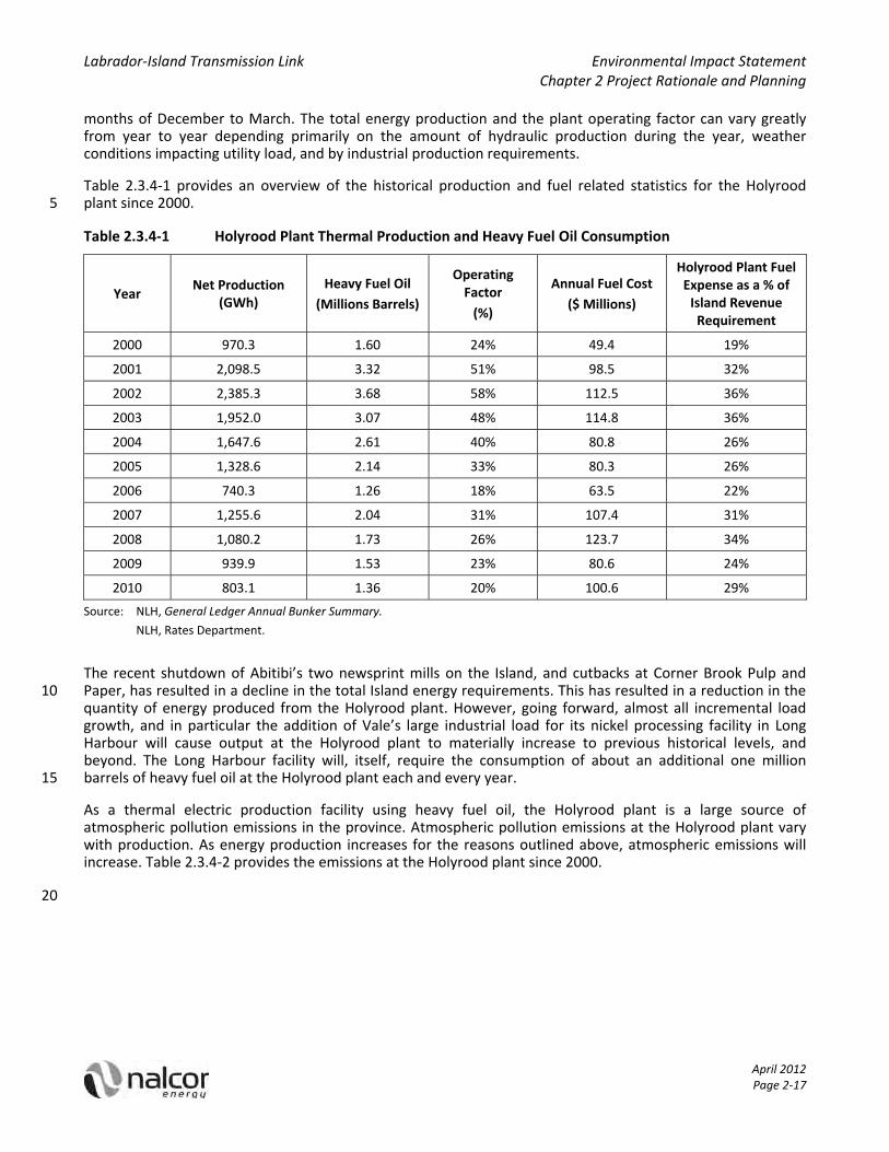
Labrador‐Island Transmission Link Environmental Impact Statement Chapter 2 Project Rationale and Planning
April 2012 Page 2‐17
months of December to March. The total energy production and the plant operating factor can vary greatly from year to year depending primarily on the amount of hydraulic production during the year, weather conditions impacting utility load, and by industrial production requirements.
Table 2.3.4‐1 provides an overview of the historical production and fuel related statistics for the Holyrood plant since 2000. 5
Table 2.3.4‐1 Holyrood Plant Thermal Production and Heavy Fuel Oil Consumption
Year Net Production
(GWh)
Heavy Fuel Oil
(Millions Barrels)
Operating Factor
(%)
Annual Fuel Cost
($ Millions)
Holyrood Plant Fuel Expense as a % of Island Revenue Requirement
2000 970.3 1.60 24% 49.4 19%
2001 2,098.5 3.32 51% 98.5 32%
2002 2,385.3 3.68 58% 112.5 36%
2003 1,952.0 3.07 48% 114.8 36%
2004 1,647.6 2.61 40% 80.8 26%
2005 1,328.6 2.14 33% 80.3 26%
2006 740.3 1.26 18% 63.5 22%
2007 1,255.6 2.04 31% 107.4 31%
2008 1,080.2 1.73 26% 123.7 34%
2009 939.9 1.53 23% 80.6 24%
2010 803.1 1.36 20% 100.6 29%
Source: NLH, General Ledger Annual Bunker Summary.
NLH, Rates Department.
The recent shutdown of Abitibi’s two newsprint mills on the Island, and cutbacks at Corner Brook Pulp and Paper, has resulted in a decline in the total Island energy requirements. This has resulted in a reduction in the 10 quantity of energy produced from the Holyrood plant. However, going forward, almost all incremental load growth, and in particular the addition of Vale’s large industrial load for its nickel processing facility in Long Harbour will cause output at the Holyrood plant to materially increase to previous historical levels, and beyond. The Long Harbour facility will, itself, require the consumption of about an additional one million barrels of heavy fuel oil at the Holyrood plant each and every year. 15
As a thermal electric production facility using heavy fuel oil, the Holyrood plant is a large source of atmospheric pollution emissions in the province. Atmospheric pollution emissions at the Holyrood plant vary with production. As energy production increases for the reasons outlined above, atmospheric emissions will increase. Table 2.3.4‐2 provides the emissions at the Holyrood plant since 2000.
20

Labrador‐Island Transmission Link Environmental Impact Statement Chapter 2 Project Rationale and Planning
April 2012 Page 2‐18
Table 2.3.4‐2 Atmospheric Emissions at the Holyrood Generating Station (tonnes)
Year Carbon Dioxide (CO2) Sulphur Dioxide
(SO2) Nitrous Oxide (NOx)
Particulate Matter (PM)
2000 799,546 10,268 1,733 988
2001 1,636,930 20,784 3,893 2,059
2002 1,817,499 23,235 4,553 2,294
2003 1,518,955 19,551 3,805 1,918
2004 1,290,828 16,819 3,239 780
2005 1,062,231 13,648 2,792 1,374
2006 625,084 5,370 1,710 564
2007 1,012,280 6,234 2,489 551
2008 861,891 4,880 2,077 345
2009 769,209 3,937 1,819 211
2010 677,729 2,994 1,648 216
Source: NLH, Annual Air Emissions Report.
Note: Since 2006 lower emissions have been related to the use of lower sulphur fuel oil in addition to reduced output.
In addition to its own generating capability, NLH has power purchase agreements (PPAs) with a number of NUGs including two 27 MW wind farms. The combined capability of these PPAs is 178.8 MW with a firm energy 5 capability of 879 GWh annually.
Both Newfoundland Power and Corner Brook Pulp and Paper have generating facilities on the Isolated Island System which total 261.5 MW with a firm energy capability of 1,117 GWh annually.
Island Grid Generation Capability
The total interconnected generation capability from all sources on the existing Isolated Island System is 1,958 10 MW with a firm and average energy capability of 8,953 GWh and 9,843, respectively. Table 2.3.4‐3 provides a listing of the Island’s generation capability.
Table 2.3.4‐3 Island Grid Generation Capability
Existing Island Grid Net Capacity (MW) Firm Energy (GWh) Average Energy (GWh)
NLH Hydroelectric 927 3,961 4,510
NLH Thermal 590 2,996 2,996
Newfoundland Power 140 324 428
Corner Brook Pulp and Paper 121 793 879
Star Lake ‐ Exploits 106 634 761
Non Utility Generators 73 245 269
Total Existing 1,958 8,953 9,843
Source: Exhibit 16 (NLH 2010b, internet site).
Labrador‐Island Transmission Link Environmental Impact Statement Chapter 2 Project Rationale and Planning
April 2012 Page 2‐19
2.3.4.2 Island Grid Transmission
NLH has a total of 54 high voltage terminal stations and 3,473 km of high voltage transmission lines operating at voltage levels of 230 kilovolts (kV), 138 kV, and 66/69 kV connecting generating stations to NLH customers including Newfoundland Power, industrial customers and NLH’s own rural distribution customers.
NLH’s largest bulk transmission system on the Island grid consists of 1,608 km of 230 kV transmission line 5 stretching from Stephenville in the west to St. John’s in the east, connecting generating stations with major load centres. Below the 230 kV system, NLH operates a 138 kV transmission loop between Deer Lake and Stony Brook (near Grand Falls‐Windsor) and delivers power and energy to Newfoundland Power at Stony Brook, Sunnyside, Western Avalon and Holyrood for its Stony Brook to Sunnyside and Western Avalon to Holyrood 138 kV loops. These 138 kV loops, connected between two points on the 230 kV bulk system, provide power to 10 geographic regions where the total load of the connected communities fall in the 75 MW to 225 MW range.
Beyond the 138 kV loops, NLH operates a number of radial transmission lines at 138 kV and 66/69 kV voltage levels to supply more rural and smaller industrial loads that are remote for the 230 kV bulk system, such as customers on the Great Northern Peninsula, the Connaigre Peninsula, White Bay and the Duck Pond Mine. Generally, the loads on the NLH radial systems are in the five MW to 35 MW range. 15
At the NLH customer level, Newfoundland Power operates a number of 138 kV and 66 kV transmission lines within the Island grid. Newfoundland Power lines are generally used to connect NLH bulk delivery points to Newfoundland Power customers and generating stations.
Corner Brook Pulp and Paper operates a 66 kV transmission system between its hydroelectric facilities at Deer Lake and Watson’s Brook and the mill in Corner Brook. 20
2.3.5 Transmission Reliability
Having identified the least‐cost generation expansion plans for both the Isolated Island alternative and the Interconnected Island alternative, and completed the CPW analysis to determine the least‐cost generation expansion alternative for the Island system, an analysis of the potential effect the preferred 900 MW High Voltage direct current (HVdc) interconnection between Labrador and the Island will have on transmission 25 system reliability is warranted. This section assesses transmission system reliability for the Isolated Island alternative, the Interconnected Island alternative and the Interconnected Island alternative with the Maritime Link in terms of level of exposure, measured as availability of energy supply, and level of unsupplied energy for a significant transmission system outage.
2.3.5.1 Reliability Assessment 30
System reliability issues are discussed in Technical Note: Labrador‐Island HVdc Link and Island Interconnected System Reliability (NLH 2011c, internet site), NLH’s Transmission Planning Manual (NLH 2009) and Island Transmission System Outlook Report (NLH 2010c, internet site). The following paragraphs provide a synopsis of these documents.
Both the Isolated Island and Interconnection Island alternatives were tested for compliance against NLH’s 35 accepted generation planning and transmission planning criteria. These planning criteria adhere to industry accepted practice and compliance with them assures a level of reliability that is at least consistent with historical experience.
Within any electrical system there are always low probability, high consequence events that could result in violation of criteria and the subsequent inability to fully supply customer load. Because of the low probability 40 of occurrence, and the often high cost of mitigating the occurrence, utilities accept the risk and develop response plans to react should the low probability event occur. In the NLH system there are low probability events in the existing system, in the future Isolated Island Expansion Plan, and in the Interconnected Island Expansion Plan that, should they occur, fall into this category. Analysis has been completed to assess the

Labrador‐Island Transmission Link Environmental Impact Statement Chapter 2 Project Rationale and Planning
April 2012 Page 2‐20
current day level of risk and exposure in comparison to the risks and exposures associated with future Island Isolated and Island Interconnected expansion plans as a basis to determine whether further mitigation is required.
For the current Island System, the loss of the 230 kV Transmission Line (TL) 202/206 transmission corridor between Bay d’Espoir and Sunnyside is an accepted risk that could, if it happened at certain times of the year, 5 result in an inability to supply full load. Nalcor’s analysis indicates that for the system in 2012, the probability of this loss occurring at a time that will result in load curtailment is approximately 2%. The expected level of load curtailment during the event would be between 0 and 80,000 megawatt hours (MWh) depending on what time of year the outage occurs (based on assumptions in the Technical Note). This is representative of the level of risk and exposure that has been present on the Island System for many years. The Technical Note also 10 indicates that for the Isolated Island future, both the probability of occurrence and the maximum exposure associated with this event improve, particularly as more generating capacity is added to the Avalon Peninsula (simple cycle combustion turbine (CT) power plant and combined cycle combustion turbine (CCCT) power plant) and the 230 kV transmission line between Bay d’Espoir and Western Avalon is constructed.
The addition of a 900 MW HVdc transmission line between Muskrat Falls in Labrador and Soldiers Pond on the 15 Island portion of the province has raised questions regarding the effect that such a change will have on the reliability of the Interconnected Island System. The Technical Note also presents a detailed assessment of the reliability implications for the link and determines that a bipole transmission failure resulting in the loss of 900 MW of supply results in risk and exposure numbers at least comparable to those for the TL 202/206 loss in the existing system. While the probability of an occurrence resulting in curtailment of customer load is lower 20 (0.15% to 0.65%) when compared to 2% in the current case, the level of load curtailment could be between 0 and 94,000 MWh by 2036 and declining thereafter.
The Technical Note also discusses the proposed Maritime Link between the Island of Newfoundland and Nova Scotia and the effect this addition would have on system reliability. The analysis demonstrates that the Maritime Link improves the Island Interconnected System reliability. For the case of the loss of the 900 MW 25 supply from Labrador, the probability that this event would result in curtailment of load is reduced to less than 0.1%, and the level of curtailment to between 0 and 16,000 MWh.
Table 2.3.5‐1 summarizes the exposure levels and unsupplied energy for the Isolated Island, Interconnected and Interconnected with Maritime Link Scenarios.
The probability of a transmission line failure that results in the inability to supply all customer load is 30 dependent, in part, on the mechanical design of the transmission line itself. Transmission line design methods today consider the meteorological loadings (wind and ice) along the transmission line route, the return periods of weather events, the transmission line materials (wood, steel), and utilize reliability based methods to provide a coordinated transmission line design with known failure rates and modes for expected meteorological conditions. At a high level, a 1:50 year return period for a weather event means that one can 35 expect the design load to occur at least once in 50 years. The probability of the 1:50 year storm occurring in any one year is 2%. Based on NLH’s experience with weather related damage to existing 230 kV transmission lines on the Avalon Peninsula, analysis was conducted to determine the return periods of the various storms. The results of the analysis, Reliability Study of Transmission Lines on the Avalon and Connaigre Peninsulas (NLH 1996, internet site) filed as Exhibit 85 provides details on the subject. Basic outcomes from this study include 40 the identification of the 1:50 year return period load levels, the design return periods for existing 230 kV transmission lines, and NLH’s decision to use the 1:50 year return period loads for all new 230 kV transmission line construction on the Avalon Peninsula.

Labrador‐Island Transmission Link Environmental Impact Statement Chapter 2 Project Rationale and Planning
April 2012 Page 2‐21
Table 2.3.5‐1 Level of Exposure and Unsupplied Energy
Year
Load Forecast Island Standby
Generation (MW)
Level of Exposure Load Exceeds Generation Availability
(%)
Unsupplied Energy Worst 2 Week Window
MW GWh Annual Hours
Annual %
MWh % of Annual
Isolated Island – TL 202/206 Outage
2012 1,571 7,850 635.1 4,318 49.29 98.02 79,969 1.02
2017 1,704 8,666 965.2(a) 865 9.87 99.605 13,435 0.16
2021 1,757 8,967 965.2 1,206 13.67 99.449 19,838 0.22
2022 1,776 9,065 1,085.2(b) 200 2.28 99.909 2,622 0.029
2027 1,856 9,464 1,185.2(c) 50 0.57 99.977 553 0.006
2032 1,934 9,860 1,235.2(d) 0 0 100.0 0 0
2037 2,006 10,228 1,277.7(e) 58 0.66 99.974 649 0.006
Island Interconnected – Bipole Outage
2017 1,704 8,666 1,468.5 637 7.27 99.854 14,384 0.16
2022 1,776 9,065 1,418.5(f) 1,431 16.34 99.673 37,019 0.40
2027 1,856 9,464 1,368.5(g) 2,279 26.02 99.480 66,883 0.70
2032 1,934 9,860 1,368.5 2,691 30.72 99.386 85,888 0.87
2036 1,992 10,157 1,391.5(h) 2,831 32.32 99.354 93,744 0.92
2037 2,006 10,228 1,561.5(i) 1,683 19.21 99.616 50,900 0.498
Island Interconnected – Bipole Outage – Maritime Link In Service
2017 1,704 8,666 1,768.5 0 0 100.0 0 0
2022 1,776 9,065 1,718.5(f) 19 0.22 99.996 389 0.004
2027 1,856 9,464 1,668.5(g) 281 3.20 99.936 6,019 0.064
2032 1,934 9,860 1,668.5 626 7.14 99.986 15,765 0.160
2037 2,006 10,228 1,861.5(h)(i) 118 1.34 99.973 2,342 0.022
Source: Exhibit 106 (NLH 2011c, internet site). (a) 230 kV transmission line Bay d’Espoir to Western Avalon is built prior to 2017 increasing transfer to east coast for loss of
TL 202 and TL 206. (b) 170 MW CCCT in 2022 at Holyrood and Hardwoods 50 MW CT retired in 2022. 5 (c) 50 MW CT in 2024 and 50 MW CT in 2027 both assumed on Avalon Peninsula. (d) 50 MW CT in 2030. (e) Holyrood units replaced with 170 MW CCCT (1&2 in 2033 + 3 in 2036). (f) Hardwoods 50 MW CT retired in 2022. (g) Stephenville 50 MW CT retired in 2024. 10 (h) 23 MW Portland Creek in 2036. (i) 170 MW CCCT in 2037.
Given reliability‐based designs ranging from a 1:10 year return period for existing wood pole lines, to a 1:25 year return period for rebuilt steel lines on the Avalon and a 1:50 year return period for the proposed Bay

Labrador‐Island Transmission Link Environmental Impact Statement Chapter 2 Project Rationale and Planning
April 2012 Page 2‐22
d’Espoir to Western Avalon 230 kV transmission line, NLH adopted the 1:50 year return period as the basis of design for the HVdc transmission line between Labrador and the Island portion of the province.
In the context of the analysis completed in the Technical Note on reliability, increasing the return period of the HVdc transmission line design from 1:50 years to, say 1:150 years, would reduce the probability of the occurrence of the event resulting in inability to supply all customer load. For the Interconnected Island 5 alternative with a 1:50 year return period design for the HVdc line the probability of occurrence is 0.15% to 0.65% (availability 99.35% to 99.85%). If the HVdc line return period were increased to 1:150 years, the probability of occurrence of the event resulting in inability to supply all customer load would be 0.04% to 0.22% (availability 99.78% to 99.95%). However, the level of load curtailment (i.e., quantity of unsupplied energy during the two‐week anticipated repair interval after an event), should the event occur, would not 10 change with the change in design return period. In other words, increasing the return period of the line design reduces the probability of a failure for a given storm, but when the line failure happens the same number of customers will be without electricity. In essence, increasing the return period of the line design alone solves only one aspect of the exposure to Island customers for loss of the Labrador–Island Transmission Link.
A comparison of the exposure levels and unsupplied energy between the Interconnected Island alternative and 15 the Interconnected Island with Maritime Link alternative, as shown in Table 2.3.5‐1, highlights the reductions in unsupplied energy that can be attributed to the additional 300 MW of capacity available via the Maritime Link following the outage to the Labrador‐Island Transmission Link. Although the Maritime Link is nominally rated at 500 MW, import capacity from New Brunswick into Nova Scotia is currently limited to 300 MW. In both the Interconnected Island and the Interconnected Island with Maritime Link alternatives, the Labrador‐20 Island Transmission Link is built to a 1:50 year return period. The availability of a 300 MW import to the Island via the Maritime Link reduces the level of curtailment from 0 – 94,000 MWh to 0 – 16,000 MWh. In other words, the fact that the Maritime Link provides an alternate path for capacity and energy following and outage to the Labrador–Island Transmission Link, the probability of unsupplied energy is reduced and the expected level of unsupplied energy is reduced to less than 20% of what would otherwise be expected without the 25 Maritime Link. This translates to fewer customers being without electricity for a shorter period of time during the outage.
The analysis provided in the Technical Note demonstrates the effect that adding 50 MW CTs in the Interconnected Island alternative has on the exposure levels (the probability of an outage) and unsupplied energy (the amount of energy that will not be supplied as a result of the outage). This section of the Technical 30 Note on reliability provides a useful tool in assessing system additions to meet a predefined target. For example, if one were to assume a desired reliability level based upon an availability value of 99.5% and an unsupplied energy not to exceed 35,000 MWh for a two week outage window, one can determine the number and timing of 50 MW CTs required to maintain the criteria. As an example (not meant to be taken as a recommendation) the number and timing of 50 MW CTs could be as per Table 6 in Exhibit 106: 35
2022: 1 x 50 MW CT for availability of 99.76% and unsupplied energy of 27,000 MWh;
2027: 2 x 50 MW CT for availability of 99.82% and unsupplied energy of 31,000 MWh; and
2032: availability of 99.71% and unsupplied energy of 35,000 MWh – new CT in 2033.
The analysis indicates that reduction in unsupplied energy due to loss of the HVdc transmission line in the Interconnected Island alternative is better managed through the addition of 50 MW CTs as required to meet 40 the curtailment target, rather than through investments in increasing the HVdc line design return period beyond the existing 1:50 years carried in the basis of design.
Continued operation of the HVdc converter station at Soldiers Pond requires that the underlying 230 kV ac transmission system on the Island remains relatively intact. Analysis has been conducted using PSS®E to ensure successful operation following loss of a single 230 kV transmission line. Given that the 230 kV transmission 45 system has been designed with equivalent return periods on the order of 1:10 years for wood pole lines, 1:25 years for rebuilt steel lines and 1:50 years for new 230 kV transmission lines, building the HVdc line to a
Labrador‐Island Transmission Link Environmental Impact Statement Chapter 2 Project Rationale and Planning
April 2012 Page 2‐23
design load beyond 1:50 years is viewed as ineffective. Assuming a major storm with a return period in excess of 1:50 years, one can expect damage to most, if not all, 230 kV transmission lines. Building the HVdc line to withstand the 1:100 year storm, for example, would mean that the only transmission line remaining in service would be the HVdc line. Without the support of the underlying 230 kV ac transmission system the HVdc converter station would not be able to function, nor deliver energy to customers. 5
Based upon the reliability analysis, NLH sees no compelling reason to move away from a 1:50 year return period for the HVdc line design. In the absence of the Maritime Link, the addition of 50 MW CTs is the most effective means to limit exposure and unsupplied energy / load curtailment for the low probability, high consequence event. With alignment on the limit of exposure, 50 MW CT additions can be added to the Island Interconnected System expansion plan to satisfy the criteria. 10
2.3.5.2 Transmission Reliability Summary
In conclusion, the reliability analysis demonstrates that the Interconnected Island alternative with the Labrador–Island Transmission Link designed for a 1:50 year return period will have a reliability level similar to that of the existing Isolated Island System on measures of probability of exposure and unsupplied energy during the outage. Further, the addition of the Maritime Link or 50 MW CTs to the Interconnected Island 15 alternative are effective in reducing both the probability of exposure to an outage and the level of unsupplied energy during the outage.
Based on the results of the transmission reliability analysis Nalcor is recommending that the Labrador–Island Transmission Link overhead line design be based on a 1:50 year return period. This level of line design provides for an Interconnected Island alternative having a probability of exposure to an outage and a level of 20 unsupplied energy during an outage similar to that of the Isolated Island system today. Therefore, Nalcor sees no justification in increased capital expenditures on additional CTs and is therefore recommending no additional CTs at this time.
2.3.6 Identification of Need for Transmission
As part of the regular system planning process, NLH completes a review of the transmission system to assess 25 its adequacy. The Island Transmission System Outlook Report (NLH 2010c, internet site) provides an overview of the transmission system requirements in the five to 10 year time frame. Given the identified need for new generation supply in the near term, the report offers the following important transmission issues that must be considered when new generation sources are added to the Island system:
the 230 kV transmission system east of Bay d’Espoir is both thermally and voltage constrained with respect 30 to increasing power deliveries to the Avalon Peninsula load centre;
new generation sites off the Avalon Peninsula will require additional 230 kV transmission line reinforcement along the Bay d’Espoir to St John’s corridor; and
the 230 kV transmission system west of Bay d’Espoir experiences high voltage levels during the year, which may affect generator ratings for new generation sources in this part of the system. 35
Following development of generation expansion plans through the generation planning process, the transmission system effects of the proposed generation sites can be more fully assessed and transmission system additions more fully defined.
2.3.7 System Capability versus Load Forecast
Table 2.3.7‐1 provides a summary of the 2010 PLF electric power and energy requirements for the system 40 period 2010 to 2029 compared against supply capacity and firm capability to determine the timing and need for new generation resources. For the Isolated Island System, capacity deficits commence in 2015, with firm energy deficits commencing in 2021 (both of which are illustrated by the shaded cells in Table 2.3.7‐1). Capacity deficits trigger the need for the next generation source by 2015.
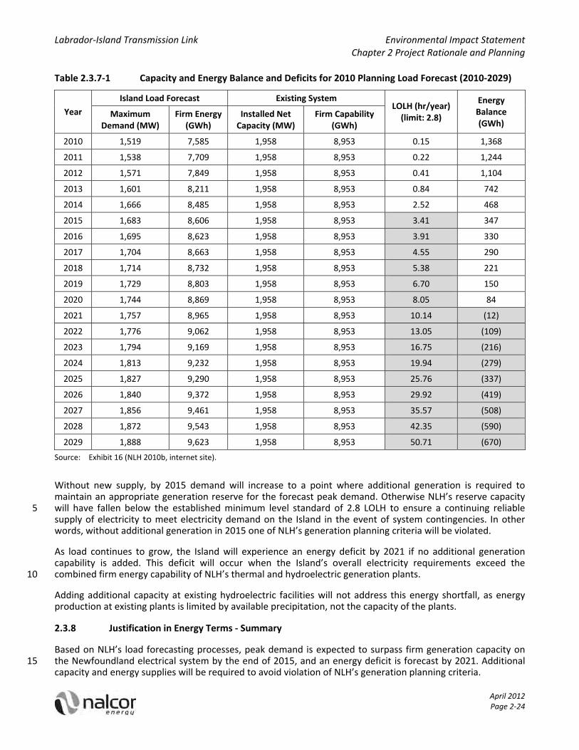
Labrador‐Island Transmission Link Environmental Impact Statement Chapter 2 Project Rationale and Planning
April 2012 Page 2‐24
Table 2.3.7‐1 Capacity and Energy Balance and Deficits for 2010 Planning Load Forecast (2010‐2029)
Year
Island Load Forecast Existing System LOLH (hr/year) (limit: 2.8)
Energy Balance (GWh)
Maximum Demand (MW)
Firm Energy (GWh)
Installed Net Capacity (MW)
Firm Capability (GWh)
2010 1,519 7,585 1,958 8,953 0.15 1,368
2011 1,538 7,709 1,958 8,953 0.22 1,244
2012 1,571 7,849 1,958 8,953 0.41 1,104
2013 1,601 8,211 1,958 8,953 0.84 742
2014 1,666 8,485 1,958 8,953 2.52 468
2015 1,683 8,606 1,958 8,953 3.41 347
2016 1,695 8,623 1,958 8,953 3.91 330
2017 1,704 8,663 1,958 8,953 4.55 290
2018 1,714 8,732 1,958 8,953 5.38 221
2019 1,729 8,803 1,958 8,953 6.70 150
2020 1,744 8,869 1,958 8,953 8.05 84
2021 1,757 8,965 1,958 8,953 10.14 (12)
2022 1,776 9,062 1,958 8,953 13.05 (109)
2023 1,794 9,169 1,958 8,953 16.75 (216)
2024 1,813 9,232 1,958 8,953 19.94 (279)
2025 1,827 9,290 1,958 8,953 25.76 (337)
2026 1,840 9,372 1,958 8,953 29.92 (419)
2027 1,856 9,461 1,958 8,953 35.57 (508)
2028 1,872 9,543 1,958 8,953 42.35 (590)
2029 1,888 9,623 1,958 8,953 50.71 (670)
Source: Exhibit 16 (NLH 2010b, internet site).
Without new supply, by 2015 demand will increase to a point where additional generation is required to maintain an appropriate generation reserve for the forecast peak demand. Otherwise NLH’s reserve capacity will have fallen below the established minimum level standard of 2.8 LOLH to ensure a continuing reliable 5 supply of electricity to meet electricity demand on the Island in the event of system contingencies. In other words, without additional generation in 2015 one of NLH’s generation planning criteria will be violated.
As load continues to grow, the Island will experience an energy deficit by 2021 if no additional generation capability is added. This deficit will occur when the Island’s overall electricity requirements exceed the combined firm energy capability of NLH’s thermal and hydroelectric generation plants. 10
Adding additional capacity at existing hydroelectric facilities will not address this energy shortfall, as energy production at existing plants is limited by available precipitation, not the capacity of the plants.
2.3.8 Justification in Energy Terms ‐ Summary
Based on NLH’s load forecasting processes, peak demand is expected to surpass firm generation capacity on the Newfoundland electrical system by the end of 2015, and an energy deficit is forecast by 2021. Additional 15 capacity and energy supplies will be required to avoid violation of NLH’s generation planning criteria.
Labrador‐Island Transmission Link Environmental Impact Statement Chapter 2 Project Rationale and Planning
April 2012 Page 2‐25
Following a review of generation and transmission planning criteria, the Strategist® modelling framework, and the existing Island grid’s generation capability, a need for new generation supply has been identified for capacity and energy in 2015 and 2021, respectively. Given the need for generation additions, the Island Transmission System Outlook Report identifies potential areas of concern that must be addressed under the transmission planning criteria once the generation expansion plans are developed. 5
A decision was made in 2010 as to what new generation source would be selected to allow sufficient time to bring generation and related infrastructure on line in time (see Section 2.10).
2.4 Economic Analysis of the Project
Having established an energy and capacity shortfall, the next step in the planning process is to develop the least‐cost generation expansion plan to meet the forecast requirements. In order to establish the economic 10 justification for the Project, Nalcor developed the optimum expansion plan without the Project using a portfolio of renewable and thermal alternatives and the optimum expansion with the Project and also energy supplied from Labrador developments.
This section also explains the methodology used to evaluate the two generation expansion plans from an economic perspective. It includes a discussion of the thresholds for economic viability and presents the results 15 of the analysis, including a sensitivity analysis which demonstrates how changes in the underlying assumptions affect the results.
2.4.1 Economic Evaluation Methodology
Having determined a need for new sources of electricity, the next step in NLH’s system planning process involves the determination of the least‐cost option for the supply of electricity to its customers. An important 20 tool in this analysis is a software tool called Ventyx Strategist®. It is an integrated, strategic planning computer model that performs, amongst other functions, generation system reliability analysis, projection of costs simulation and generation expansion planning analysis. Strategist® is used by many utilities throughout the industry and has broad acceptance by regulatory bodies.
The software can analyze and plan the generation requirements of the system for a given load forecast and for 25 specific parameters as identified by the utility that can include resource limitations, fuel prices, capital costs and operating and maintenance costs. Strategist® evaluates all of the various combinations of resources and produces a number of generation expansion plans, including the least‐cost plan, to supply the load forecast within the context of the power system reliability criteria and other technical limitations as set by the utility.
Generation expansion planning and analysis provides the incremental production costing for all the 30 operational and capital expenses necessary for NLH to reliably supply electricity to meet the forecasted requirements for power and energy over time. For each year of the planning period, the Strategist® software calculates NLH’s production expenses given the configuration of thermal and renewable alternative resources in economic order at its disposal, power purchases from third parties, annual capital related expenses as new plants come on line, and Operating and Maintenance costs, including fuel costs. 35
Strategist® calculates annual production‐ and capital‐related costs estimates in nominal Canadian dollars for each year of the long‐term planning period. To convert all future costs to a common present day period, a planning metric called CPW is calculated. CPW is the present value of all incremental utility capital and operating costs incurred to reliably meet a specified load forecast given a prescribed set of reliability criteria. An alternative long‐term supply future that has a lower CPW than another supply alternative will be the 40 preferred investment strategy for the utility where all other constraints, such as access to capital, are satisfied. The selection of an alternative investment path with a lower CPW is consistent with the objective of providing least‐cost power because an alternative with a lower CPW results in an overall lower regulated revenue requirement from the customers served. Consistent with a discounted cash flow analysis, the CPW analysis likewise requires the selection of a discount rate to account for the time value of money. The discount rate has 45

Labrador‐Island Transmission Link Environmental Impact Statement Chapter 2 Project Rationale and Planning
April 2012 Page 2‐26
been set to match NLH’s regulated average long run weighted cost of capital which, for the 2010 generation expansion analysis being reported herein, was 8%.
To facilitate analysis, Strategist® was used to develop least‐cost Isolated Island (without the Project) and Interconnected Island (with the Project) generation expansion plans. A comparison of the two expansion plans will be provided, and the plan with the lowest CPW is the preferred expansion plan. 5
2.4.1.1 Key Inputs to the Strategist® Cumulative Present Worth Analysis
In preparing to carry out a generation expansion analysis using Strategist®, the inputs into the planning model are reviewed and updated as required. Key inputs and parameters are discussed in the following subsections:
Planning Load Forecast
This review utilizes the 2010 PLF as prepared by the NLH System Planning Department and has been presented 10 in detail in Section 2.3.1.
Time Period of Study
The time period that the study will cover must be defined and all other inputs must be developed to cover this period. The time period for the 2010 expansion analysis is 50 years after in service of the Project in order to cover its service life. Thus the full period of analysis is from 2010 to 2067. 15
Load Shape
Hourly load shapes for each month of the year are required. NLH uses a representative week to model each month, with inputs based on hourly system load readings for the Island grid. The applicable load shape illustrated for the week of the first month of each quarter is provided in Figure 2.4.1‐1.
Figure 2.4.1‐1 Load Shape Used in Strategist® Cumulative Present Worth Analysis 20
Source: Exhibit 2 (NLH 2011d, internet site).

Labrador‐Island Transmission Link Environmental Impact Statement Chapter 2 Project Rationale and Planning
April 2012 Page 2‐27
Escalation Series
Escalation rates for capital, and Operating and Maintenance costs are developed annually based on external projections received from the Conference Board of Canada and Global Insight. In addition to forecasts for general inflation and related Operating and Maintenance costs, escalation cost indices are developed for NLH primary construction projects in generation, transmission and distribution. These composite indices represent 5 a weighting by input construction cost item. Forecasts for Producer Price Indices (PPIs) regularly prepared by Global Insight are used to forecast each composite index. Separate construction project escalation indices have been developed for Muskrat Falls and the Project (Nalcor 2011b, internet site). The escalation rates used in the present analysis are provided in Table 2.4.1‐1.
Table 2.4.1‐1 Inflation and Escalation Forecast Used in Strategist® Cumulative Present Worth Analysis 10
Year
General Inflation
2009 = 1.000
Electric Utility Construction Price Escalation 2009 = 1.000
Project 2010 = 1.000
Operating and Maintenance 2009 = 1.000
GDP Im
plicit Price
Deflator
Can
adian CPI
CT Plant
CCCT Plant
Hydraulic Plant
Tran
smission Line
Tran
sform
er
Station
Distribution Line
Muskrat Falls
Labrador‐Island
Tran
smission Link
More M
aterial
Less Lab
our
Same M
aterial
Same Lab
our
More Lab
our
Less M
aterial
Labour Only
2000 0.825 0.835 0.776 0.763 0.765 0.829 0.873 0.846
2001 0.834 0.856 0.784 0.773 0.785 0.836 0.894 0.851
2002 0.843 0.875 0.804 0.792 0.798 0.849 0.911 0.857
2003 0.871 0.899 0.813 0.798 0.807 0.845 0.884 0.858
2004 0.899 0.915 0.827 0.812 0.842 0.875 0.894 0.861
2005 0.930 0.935 0.858 0.850 0.863 0.885 0.910 0.877
2006 0.953 0.954 0.894 0.884 0.891 0.923 0.935 0.936
2007 0.983 0.975 0.922 0.913 0.913 0.941 0.949 0.957
2008 1.021 0.997 0.973 0.967 0.971 1.003 0.981 0.991
2009 1.000 1.000 1.000 1.000 1.000 1.000 1.000 1.000 1.000 1.000 1.000 1.000
2010 1.024 1.022 0.982 0.984 0.991 0.993 0.988 0.993 1.000 1.000 1.022 1.025 1.028 1.030
2011 1.048 1.046 0.998 1.000 1.008 1.015 0.993 1.009 1.020 1.020 1.044 1.051 1.057 1.061
2012 1.071 1.069 1.020 1.020 1.028 1.042 1.003 1.029 1.050 1.040 1.067 1.077 1.087 1.093
2013 1.095 1.093 1.046 1.043 1.051 1.072 1.022 1.054 1.110 1.080 1.090 1.104 1.117 1.126
2014 1.118 1.116 1.081 1.074 1.080 1.111 1.051 1.079 1.160 1.120 1.114 1.132 1.148 1.160
2015 1.140 1.138 1.105 1.098 1.103 1.139 1.075 1.102 1.200 1.160 1.139 1.160 1.180 1.195
2016 1.163 1.161 1.108 1.103 1.106 1.141 1.086 1.120 1.230 1.200 1.164 1.189 1.213 1.231
2017 1.186 1.184 1.121 1.116 1.117 1.155 1.096 1.136 1.260 1.240 1.190 1.219 1.247 1.268
2018 1.210 1.208 1.140 1.135 1.134 1.176 1.110 1.154 1.300 1.290 1.216 1.249 1.282 1.306
2019 1.234 1.232 1.162 1.155 1.152 1.198 1.127 1.175 1.243 1.280 1.318 1.345
Post 2019 Annual % Change
2.0% 2.0% 2.0% 2.0% 2.0% 2.0% 2.0% 2.0% n/a n/a 2.2% 2.5% 2.8% 3.0%
Source: Exhibit 3 (Nalcor 2011c, internet site).
Note: CPI = Consumer Price Index.

Labrador‐Island Transmission Link Environmental Impact Statement Chapter 2 Project Rationale and Planning
April 2012 Page 2‐28
Heavy Fuel Oil and Distillate Market Prices
The PIRA of New York, an international supplier of energy market analysis and forecasts, and oil market intelligence in particular, independently supplies the fuel oil price forecasts that are used for costing thermal fuel expenses for the provincial power system. These forecasts are updated for the most current long‐term projections at the beginning of each generation planning expansion analysis. These market based fuel oil price 5 forecasts are used in production costing for the existing Holyrood plant and CT thermal plants, plus for any new CCCTs or CTs that would be constructed in future periods. The prices used in the 2010 CPW analysis are presented in Table 2.4.1‐2, along with a long‐term price update as of May 2011 that was included in the CPW sensitivity analysis in Section 2.7.1.1.
Table 2.4.1‐2 Thermal Fuel Oil Price Forecast Used in Strategist® Cumulative Present Worth Analysis 10
Year
Reference Forecast at Jan 2010 Reference Forecast at May 2011
#6 0.7%s
($Cdn/barrel)
#6 2.2%s
($Cdn/barrel)
Diesel
($Cdn/l)
#6 0.7%s
($Cdn/barrel)
#6 2.2%s
($Cdn/barrel)
Diesel
($Cdn/l)
2010 81.30 79.60 0.674
2011 83.20 80.50 0.700 102.90 95.70 0.908
2012 90.90 88.00 0.760 118.40 113.70 0.990
2013 98.80 95.50 0.815 122.50 119.20 1.025
2014 102.60 99.00 0.850 126.90 123.40 1.060
2015 106.80 103.00 0.905 130.80 127.10 1.100
2016 111.10 107.00 0.945 135.60 131.60 1.140
2017 116.30 111.50 0.990 140.70 136.00 1.180
2018 121.10 115.60 1.030 144.30 139.00 1.210
2019 124.90 118.60 1.065 147.90 141.80 1.240
2020 129.20 120.30 1.100 151.50 142.80 1.275
2021 132.80 123.10 1.155 153.60 144.20 1.315
2022 136.00 125.80 1.195 155.50 145.80 1.350
2023 139.10 128.50 1.235 157.80 147.70 1.385
2024 142.10 131.10 1.275 160.70 150.20 1.425
2025 145.00 133.70 1.315 162.80 152.00 1.460
Source: Exhibit 4 (Nalcor and NLH 2010, internet site).
Nalcor response to MHI‐Nalcor‐126 (Nalcor 2011d, internet site).
Note: $Cdn = Canadian dollars
Product prices reflect landed values on Avalon Peninsula.
Diesel represents No. 2 distillate gas turbine fuel for Holyrood. 15 Post 2025 pricing is forecast at annual inflation of 2%.
Weighted Average Cost of Capital / Discount Rate
The generation expansion analysis for 2010 used a weighted average cost of capital (WACC) for new capital assets of 8.0% consistent with NLH regulated utility WACC assumptions prepared as of January 2010. The WACC reflects a targeted debt equity ratio of 75% for NLH regulated operations, comprised of a forecasted 20 long‐term cost of debt at 7.3% and a long‐term cost of equity at 10%. All monetary costs were modelled in current (as spent) Canadian dollars and present valued to 2010$ at the defined discount rate of 8.0%.

Labrador‐Island Transmission Link Environmental Impact Statement Chapter 2 Project Rationale and Planning
April 2012 Page 2‐29
Capital Cost Estimates
Capital costs estimates for the portfolio of alternative generation assets are based on formal feasibility studies and estimates as developed by consultants and NLH’s Project Execution and Technical Services Division. The portfolio of utility projects used in the 2010 generation expansion analysis is provided in Table 2.4.1‐3.
Table 2.4.1‐3 Portfolio of Utility Projects Used in Strategist® Cumulative Present Worth Analysis 5
Facility 2010$, Millions In‐Service Capital Cost Including Escalation and AFUDC/IDC(a)
for Isolated and Interconnected Alternatives
Island Pond $166 $199 million in 2015
Portland Creek $90 $111 million in 2018, $156 million in 2036
Round Pond $142 $185 million in 2029
Wind 2 X 27 (new) $125 $189 to $281 million, various in‐service years
Wind 1 x 25 (new) $58 $98 to $146 million, various in‐service dates
Greenfield CCCT #1 $274 $465 to $882 million, various in‐service years
Greenfield CCCT #2 $206 $346 to $644 million, various in‐service dates
CTs New $65 $75 to $209 million, various in‐service years
Holyrood FGD and ESP $458(b) $582 million in 2015
Labrador‐Island Transmission Link $1,616 $2,553 million. 75:25 debt equity financing assumption
Source: Exhibit 5H (Aces International Limited 2001, internet site);
Exhibit CE‐46 (Hatch Ltd. 2008, internet site);
Exhibits 5F, 5E and 5 (Nalcor 2010a, b, c, d, internet site);
Nalcor response to MHI‐Nalcor‐1 (Nalcor 2011d, internet site) (see detail in Exhibit 99);
Nalcor response to MHI‐Nalcor‐49.3 (AFUDC and escalation) (Nalcor 2011d, internet site); 10 Exhibit CE‐51 (Nalcor 2011e, internet site);
NLH (2010d, internet site);
NLH (2011e, f, internet site);.
SGE Acres limited (2004, internet site);
SNC‐Lavalin Inc. (1989, 2006, 2007, 2008, 2011, internet site). 15 Stantec Consulting Ltd.(2008, internet site). (a) AFUDC = allowance for funds used during construction; IDC = Interest During Construction; CCCT = combined cycle
combustion turbine; FGD = flue gas desulphurization; ESP = electrostatic precipitators. (b) 2009$.
Power Purchase Agreements 20
The annual power purchase expense incurred by NLH under existing PPAs and future PPAs are projected for input to Strategist® and are summarized in Table 2.4.1‐4.

Labrador‐Island Transmission Link Environmental Impact Statement Chapter 2 Project Rationale and Planning
April 2012 Page 2‐30
Table 2.4.1‐4 Power Purchase Agreements Used in Strategist® Cumulative Present Worth Analysis
PPA GWh per Year End Date Comment
Fermeuse Wind 84 2028 Re‐investment by NLH assumed if Isolated alternative pursued.
St. Lawrence Wind 105 2028 Re‐investment by NLH assumed if Isolated alternative pursued.
3rd Wind Farm 88 2034 Isolated Alternative only. NLH re‐investment assumed.
Corner Brook Co‐Gen 65 2023
Rattle Brook (hydro) 14 Continuous
Star Lake (hydro) 144 Continuous
Exploits Partnership (hydro)
137 Continuous
Exploits Generation (hydro)
480 Continuous
Muskrat Falls Max 4.9TWh Continuous See commentary below on pricing.
Source: Exhibit 6 (Nalcor 2011f, internet site).
Nalcor response to MHI‐Nalcor‐49.2 (Nalcor 2011d, internet site).
Muskrat Falls Power Purchase Expense
The price that NLH pays for power and energy from Muskrat Falls on behalf of Island ratepayers is a 5 cornerstone for the Lower Churchill Project. Nalcor, in consultation with its financial advisors, has approached the issue of electricity pricing for the Muskrat Falls hydroelectric facility in a manner structured to achieve certain ratepayer benefits while still facilitating Project development.
Under a regulated Cost of Service (COS) price setting environment, the annual revenue requirement for a utility asset would be comprised of: 10
COS = Operating and Maintenance Costs + Power Purchases+ Fuel + Depreciation + Return on Rate Base
Where Return on Rate Base would be comprised of a cost component for lenders (cost of debt) and a profit component for shareholders (return on equity) for a prescribed debt‐equity capital structure. This annual COS would then be divided by the output produced and sold from the asset in question to derive an average selling 15 price or rate (such as cents per kilowatt hour (kWh), or equivalent dollars per megawatt hour (MWh). An important feature of this pricing methodology is that under COS price setting, the unit rate revenue paid by ratepayers for a given asset is highest in the first year. This is because as a new regulated asset goes into rate base, the undepreciated cost of the asset is at its maximum and return on rate base is driven by undepreciated net book value. Another feature of this pricing framework is that as the equity investor earns its regulated 20 return each year, the return in dollars is also highest in the first and initial years. This is not necessarily prudent for the Muskrat Falls development in that the Island ratepayer energy requirements at the time of plant commissioning is projected to be only about 40%, or 2 terawatt hours (TWh), of the plant’s average annual production of 4.9 TWh. While the Island’s energy requirements increase over time in line with economic growth, the early‐year COS rate for Muskrat Falls power would be a significant burden for ratepayers in those 25 years. The required COS revenue for Muskrat Falls would be at its maximum and the power required by ratepayers at a minimum. In an effort to address this issue, an alternative approach to Muskrat Falls power pricing was developed that affords a number of advantages for ratepayers.
Labrador‐Island Transmission Link Environmental Impact Statement Chapter 2 Project Rationale and Planning
April 2012 Page 2‐31
To derive an appropriate price for NLH’s power purchase requirements for the Island, Nalcor undertook a supply pricing analysis for Muskrat Falls initially assuming that the total firm annual plant production was available for sale. The objective of this analysis was to determine the economic price for the project, in this instance expressed as an “escalating supply price”. It is perhaps more common in economic analysis to express economic supply prices as Levelized Unit Energy Costs. In either circumstance, the annual price, when 5 multiplied by output and discounted, equals the present value of the project’s costs given the capital and operating costs, other incurred expenses, and the cost and terms of obtaining capital. The escalating supply price is the price per MWh that recovers all costs associated with the Muskrat Falls hydroelectric development – operating and other incurred costs over time, debt service costs for the debt portion of the capital investment (as applicable) and a hurdle return on the equity portion of the capital investment. This escalating 10 supply price is lower than would be indicated initially by the COS framework. Though it escalates evenly over time, the burden on ratepayers in the critical early years is minimized. This is accomplished essentially through the equity investor’s flexibility on the timing of its equity return in the early years, relative to that in later years. Nalcor has calculated this escalating supply price for Muskrat Falls power based on the project’s cost estimates at the time of Decision Gate 2 (see Section 2.10), coupled with an Internal Rate of Return (IRR) of 15 11%, to be approximately $76/MWh in 2010$, escalating at 2% annually. The IRR was on firm power, with a 12% IRR on average power taken as an analytical benchmark for analysis purposes.
For the next step in the Muskrat Falls pricing analysis, this $76/MWh escalating supply price was then used to calculate the revenues, cash flows and shareholder returns assuming that the only market for Muskrat Falls output was the Island market. The reduction in the volume of sales assuming only the Island market, as 20 outlined above, as opposed to full annual production quantities at start up, reduced the Muskrat Falls project IRR from 11% to 8.4%. Nalcor deemed this IRR to be acceptable for a case in which only Island sales are available to Muskrat Falls, and adopted this escalating supply price framework for the present analysis. This return on equity is consistent with the present day return on equity for Newfoundland Power, and is only slightly below the long‐run projected average for NL electrical utilities. Nalcor considers this acceptable 25 because Muskrat Falls may have opportunities for additional revenues over and above those from the Island market, notably for the earlier part of the operational period before Island demand fully subscribes Muskrat Falls output.
In addition to lower prices for ratepayers for Muskrat Falls power in the early years, a further advantage to this pricing approach rests with fixing the real dollar level for the Muskrat Falls supply price across time. 30 Hydroelectric assets are very long life assets and where a power purchase price for its output is fixed in 2010$ constant real dollars, this helps to address intergenerational equity issues associated with large public investments in durable assets in the power sector – particularly as the full output of Muskrat Falls is not required by ratepayers in the early years of the project.
Service Life / Retirements 35
The service life and retirement dates for existing and new generation assets must be defined for the Strategist® expansion analysis as thermal plant replacement is an important component of generation planning and costing. The service life assumptions used in the present analysis are provided in Table 2.4.1‐5.
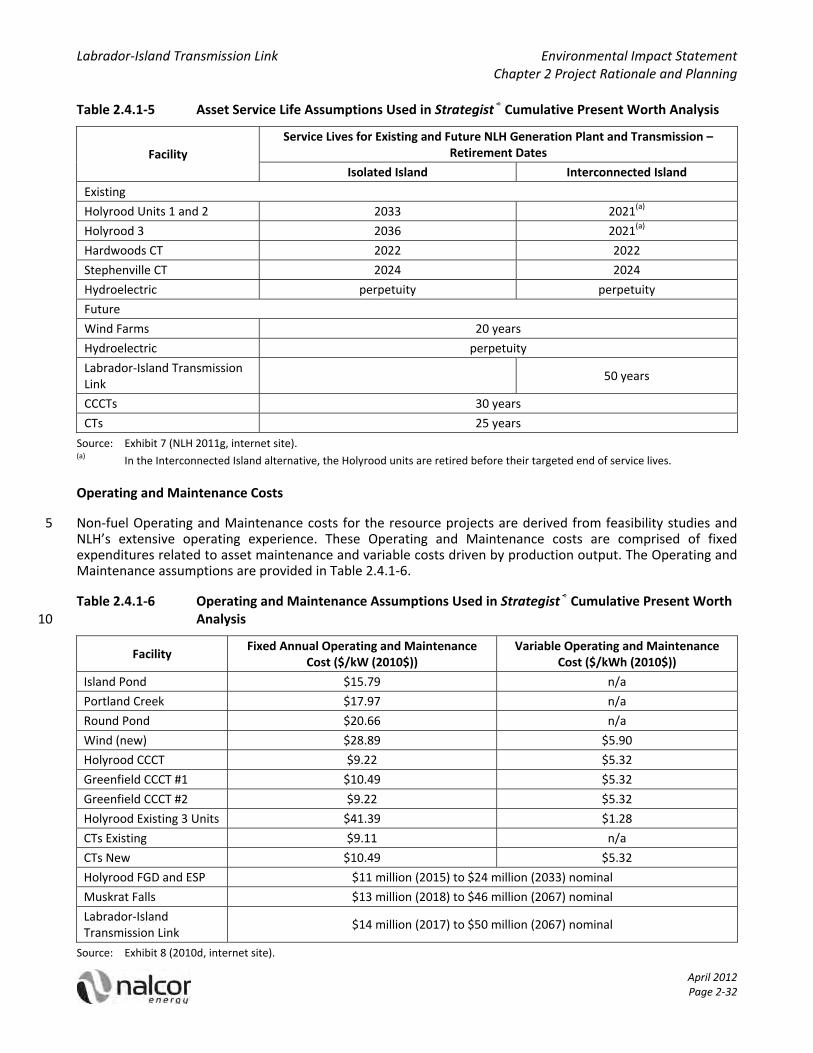
Labrador‐Island Transmission Link Environmental Impact Statement Chapter 2 Project Rationale and Planning
April 2012 Page 2‐32
Table 2.4.1‐5 Asset Service Life Assumptions Used in Strategist® Cumulative Present Worth Analysis
Facility
Service Lives for Existing and Future NLH Generation Plant and Transmission – Retirement Dates
Isolated Island Interconnected Island
Existing
Holyrood Units 1 and 2 2033 2021(a)
Holyrood 3 2036 2021(a)
Hardwoods CT 2022 2022
Stephenville CT 2024 2024
Hydroelectric perpetuity perpetuity
Future
Wind Farms 20 years
Hydroelectric perpetuity
Labrador‐Island Transmission Link
50 years
CCCTs 30 years
CTs 25 years
Source: Exhibit 7 (NLH 2011g, internet site). (a) In the Interconnected Island alternative, the Holyrood units are retired before their targeted end of service lives.
Operating and Maintenance Costs
Non‐fuel Operating and Maintenance costs for the resource projects are derived from feasibility studies and 5 NLH’s extensive operating experience. These Operating and Maintenance costs are comprised of fixed expenditures related to asset maintenance and variable costs driven by production output. The Operating and Maintenance assumptions are provided in Table 2.4.1‐6.
Table 2.4.1‐6 Operating and Maintenance Assumptions Used in Strategist® Cumulative Present Worth Analysis 10
Facility Fixed Annual Operating and Maintenance
Cost ($/kW (2010$)) Variable Operating and Maintenance
Cost ($/kWh (2010$))
Island Pond $15.79 n/a
Portland Creek $17.97 n/a
Round Pond $20.66 n/a
Wind (new) $28.89 $5.90
Holyrood CCCT $9.22 $5.32
Greenfield CCCT #1 $10.49 $5.32
Greenfield CCCT #2 $9.22 $5.32
Holyrood Existing 3 Units $41.39 $1.28
CTs Existing $9.11 n/a
CTs New $10.49 $5.32
Holyrood FGD and ESP $11 million (2015) to $24 million (2033) nominal
Muskrat Falls $13 million (2018) to $46 million (2067) nominal
Labrador‐Island Transmission Link
$14 million (2017) to $50 million (2067) nominal
Source: Exhibit 8 (2010d, internet site).

Labrador‐Island Transmission Link Environmental Impact Statement Chapter 2 Project Rationale and Planning
April 2012 Page 2‐33
Thermal Heat Rates
Per unit fuel consumption of existing and future thermal generation sources are important inputs in production costing. The heat rates utilized in Strategist® reflect a combination of NLH’s operating experience, plus external studies and estimates. The heat rates are listed in Table 2.4.1‐7.
Table 2.4.1‐7 Heat Rates Used in Strategist® Cumulative Present Worth Analysis 5
Facility Fuel Source Maximum MBTU per MWh Minimum MBTU per MWh
Existing Holyrood Units No. 6 9.78 10.39
Existing CTs No. 2 12.26 12.26
Existing Diesel Units No. 2 10.97 10.97
Future CCCTs No. 2 7.64 8.63
Future CTs No. 2 9.43 9.43
Source: Exhibit 9 Rev. 1 (NLH 2011h, internet site).
MBTU = Millions of British Thermal Units.
Generation Capacity and Energy Capability ‐ Existing and Future Resources
The monthly and annual average and firm energy production forecasts for all of the existing hydroelectric plants and wind farms are updated to incorporate the latest historical data and operational factors. Production 10 forecasts from new thermal and renewable plants are based on engineering studies estimates. Existing and future generating capacity used in Strategist® CPW Analysis is presented in Table 2.4.1‐8.
Table 2.4.1‐8 Existing and Future Generating Capacity Used in Strategist® Cumulative Present Worth Analysis
Source Net Capacity (MW) Firm Energy (GWh) Average Energy (GWh)
Existing Island Grid
NLH Hydroelectric 927 3,961 4,510
NLH Thermal 590 2,996 2,996
Customer Owned 262 1,117 1,307
Non Utility Generators 179 879 1,030
Total Existing 1,958 8,953 9,843
Future Resources
Island Pond 36 172 186
Portland Creek 23 99 142
Round Pond 18 108 139
Wind Farm 25 70 to 110
CCCT 170 1,340 n/a
CT 50 394 n/a
Muskrat Falls 824 4,540 4,910
Labrador‐Island Transmission Link
900 NA NA
Source: Exhibit 16 (NLH 2010b, internet site). 15 Muskrat Falls firm and average as per Lower Churchill Project for modeling use.

Labrador‐Island Transmission Link Environmental Impact Statement Chapter 2 Project Rationale and Planning
April 2012 Page 2‐34
Asset Maintenance Scheduling
Specific outage schedules to accommodate annual maintenance for each existing and future thermal generation asset must be included in the Strategist® analysis. Such maintenance scheduling is largely based on NLH’s operational experience and asset management planning processes and is presented in Table 2.4.1‐9.
Table 2.4.1‐9 Asset Maintenance Scheduling Used in Strategist® Cumulative Present Worth Analysis 5
Facility Weeks for Asset Maintenance Period
Holyrood Units (3) 8 weeks each staggered across off–peak months
May / June, July / August, September / October
All Other Thermal 2 weeks each April through November
All Hydroelectric Maintenance assumed to be undertaken in off–peak months (April to November)
Labrador‐Island Transmission Link Maintenance assumed to be undertaken in off–peak months (April to November)
Source: Exhibit 11 (NLH 2011i, internet site).
Forced Outage Rates
All generation production units have an associated involuntary forced outage rate leading to the unavailability of a generating unit. The forced outage rates used in this analysis are based on NLH’s operating experience and / or industry norms as tabulated by the Canadian Electricity Association. 10
Table 2.4.1‐10 Forced Outage Rates Used in Strategist® Cumulative Present Worth Analysis
NLH Facility Forced Outage Rate (%)
Combustion Turbine 10.62
Holyrood Thermal 9.64
Combined Cycle Thermal 5.00
Diesel 1.18
Existing and New Hydroelectric 0.90
Labrador‐Island Transmission Link (per pole) 0.89
Source: Exhibit 12 (NLH 2011j, internet site).
Environmental Externalities
No environmental externality cost of carbon for carbon dioxide (CO2) atmospheric emissions associated with thermal electric production has been included in production costing for thermal plants. It was also not 15 included in subsequent CPW analysis, owing to prevailing uncertainties regarding the timing, scope, and design associated with future regulatory initiatives in this regard.
2.4.2 Thresholds for Economic Viability
Two components of economic viability are relevant for this analysis. The first relates to the rate of return required for the Project. The second component of economic viability relates to the legislated requirement 20 that NLH provide least‐cost power to its customers. For both the regulated and non‐regulated Project components, the WACC is 8%. The cost of this capital is included in the CPW analysis for each alternative and forms part of the comparative analysis of the Isolated Island alternative and the Interconnected Island

Labrador‐Island Transmission Link Environmental Impact Statement Chapter 2 Project Rationale and Planning
April 2012 Page 2‐35
alternative. In the case of selecting which alternative with which to proceed, the threshold of economic viability is the alternative with the lowest CPW.
2.5 Alternative Generation Sources
This section presents a summary of the power generation supply options for both the Isolated Island and Interconnected Island alternatives. It represents a portfolio of electricity supply options that could be 5 theoretically considered to meet future generation expansion requirements for the Island. These individual supply options represent a range of choices / alternatives from local indigenous resources, to importing energy fuels from world energy markets, to interconnecting with regional North American electricity markets.
Specific supply options are initially considered and screened based on initial screening principles that align with Nalcor’s / NLH’s mandate. The initial screening (later referred to as Phase 1) is important as it enables NLH to 10 concentrate further consideration on only the technologies and alternatives that offer the highest potential to ensure effective expenditures of ratepayers’ money. In addition, prudent pricing assumptions are essential for fuel based generation alternatives. Those options that remain following the high‐level screening are input into the generation planning software models (Nalcor’s Phase 2 process) for further analysis and ultimately for the recommendation of the preferred generation expansion plan. 15
The screening principles used by Nalcor in its evaluation of alternatives are discussed in the following subsections:
Security of Supply and Reliability
Security of supply and reliability are the two most important criteria for evaluating the supply investment decision. 20
NLH is mandated to provide reliable least‐cost electrical supply to the people of the province. As part of its mandate, NLH must maintain a long‐term plan that demonstrates its ability to continue to supply the expected requirements. A realistic plan is particularly important for the Island portion of the province as it is isolated from the rest of the North American electrical grid and cannot rely on support from neighbouring jurisdictions should there be problems because of the application of unreliable technologies. 25
Because of the importance of having a realistic plan, NLH has developed an Isolated Island expansion plan that is a least‐cost optimization utilizing only proven technologies to ensure they can meet the required expectations from security of supply, reliability and operational perspectives. There must be a high level of certainty that all elements of the Isolated Island alternative plan can be permitted, constructed and integrated successfully with existing operations. Generation technologies that do not meet these rigorous requirements 30 are excluded from further consideration.
Cost to Ratepayers
NLH’s mandate, as defined in Section 3(b) of the Electrical Power Control Act, 1994 (GNL 1994), is to ensure that all sources and facilities for the production, transmission and distribution of power in the province should be managed and operated in the most efficient manner such that power delivered to consumers in the 35 province is at the lowest possible cost consistent with reliable service. Least‐cost for ratepayers is a key objective of the company and guides its business decisions, expansion plans and overall strategic direction.
Environmental Considerations
Environmental stewardship is one of Nalcor’s guiding principles. This principle is also embodied in Focusing Our Energy: Newfoundland and Labrador Energy Plan (the Energy Plan) (GNL 2007) and provides guidance to 40 Nalcor in making investment decisions. The company must meet any current environmental regulations laid out in both provincial and federal legislation and also must consider potential new environmental legislation

Labrador‐Island Transmission Link Environmental Impact Statement Chapter 2 Project Rationale and Planning
April 2012 Page 2‐36
due to the longer term nature of its generation expansion decisions. The company must also adhere to any provincial policy provided in this regard.
Risk and Uncertainty
Given the magnitude of the decisions being undertaken for generation expansion and the expenditures proposed, risk and uncertainty are key decision criteria. Nalcor considered this in its decision‐making. 5
Financial Viability of Non‐Regulated Elements
Consideration of financial viability is important to ensure that the shareholder makes an adequate rate of return and any project investment can obtain debt financing and meet debt repayment obligations.
The following subsections provide a summary of Nalcor’s screening decisions on electrical generation alternatives that could potentially be used to meet Newfoundland’s needs. 10
2.5.1 Nuclear
A nuclear reactor uses controlled nuclear reactions to produce heat energy. The heat energy is then used to produce steam. The steam is used to turn a steam turbine, which turns an electric generator to produce electricity (Figure 2.5.1‐1).
A nuclear power generation plant would not integrate well into the Isolated Island System due to the fact that 15 the nuclear plant must operate at a base load with very little output change. Nuclear plants do not ramp up or down very well, or quickly. Therefore, a nuclear generator would function well in the Isolated Island System where daily load changes are on the order of 400 MW. Furthermore, as most new designs are in the 1,000 MW range, they are sized far greater than the Isolated Island System’s minimum load of approximately 400 MW. With an inability to follow the Isolated Island System load pattern, a nuclear generator would be forced off for 20 large portions of the year.
Figure 2.5.1‐1 Components of a Typical Nuclear Reactor
Source: United States Nuclear Regulatory Commission (2011, internet site).
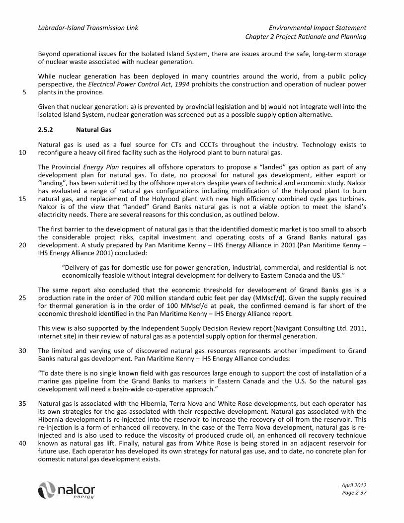
Labrador‐Island Transmission Link Environmental Impact Statement Chapter 2 Project Rationale and Planning
April 2012 Page 2‐37
Beyond operational issues for the Isolated Island System, there are issues around the safe, long‐term storage of nuclear waste associated with nuclear generation.
While nuclear generation has been deployed in many countries around the world, from a public policy perspective, the Electrical Power Control Act, 1994 prohibits the construction and operation of nuclear power plants in the province. 5
Given that nuclear generation: a) is prevented by provincial legislation and b) would not integrate well into the Isolated Island System, nuclear generation was screened out as a possible supply option alternative.
2.5.2 Natural Gas
Natural gas is used as a fuel source for CTs and CCCTs throughout the industry. Technology exists to reconfigure a heavy oil fired facility such as the Holyrood plant to burn natural gas. 10
The Provincial Energy Plan requires all offshore operators to propose a “landed” gas option as part of any development plan for natural gas. To date, no proposal for natural gas development, either export or “landing”, has been submitted by the offshore operators despite years of technical and economic study. Nalcor has evaluated a range of natural gas configurations including modification of the Holyrood plant to burn natural gas, and replacement of the Holyrood plant with new high efficiency combined cycle gas turbines. 15 Nalcor is of the view that “landed” Grand Banks natural gas is not a viable option to meet the Island’s electricity needs. There are several reasons for this conclusion, as outlined below.
The first barrier to the development of natural gas is that the identified domestic market is too small to absorb the considerable project risks, capital investment and operating costs of a Grand Banks natural gas development. A study prepared by Pan Maritime Kenny – IHS Energy Alliance in 2001 (Pan Maritime Kenny – 20 IHS Energy Alliance 2001) concluded:
“Delivery of gas for domestic use for power generation, industrial, commercial, and residential is not economically feasible without integral development for delivery to Eastern Canada and the US.”
The same report also concluded that the economic threshold for development of Grand Banks gas is a production rate in the order of 700 million standard cubic feet per day (MMscf/d). Given the supply required 25 for thermal generation is in the order of 100 MMscf/d at peak, the confirmed demand is far short of the economic threshold identified in the Pan Maritime Kenny – IHS Energy Alliance report.
This view is also supported by the Independent Supply Decision Review report (Navigant Consulting Ltd. 2011, internet site) in their review of natural gas as a potential supply option for thermal generation.
The limited and varying use of discovered natural gas resources represents another impediment to Grand 30 Banks natural gas development. Pan Maritime Kenny – IHS Energy Alliance concludes:
“To date there is no single known field with gas resources large enough to support the cost of installation of a marine gas pipeline from the Grand Banks to markets in Eastern Canada and the U.S. So the natural gas development will need a basin‐wide co‐operative approach.”
Natural gas is associated with the Hibernia, Terra Nova and White Rose developments, but each operator has 35 its own strategies for the gas associated with their respective development. Natural gas associated with the Hibernia development is re‐injected into the reservoir to increase the recovery of oil from the reservoir. This re‐injection is a form of enhanced oil recovery. In the case of the Terra Nova development, natural gas is re‐injected and is also used to reduce the viscosity of produced crude oil, an enhanced oil recovery technique known as natural gas lift. Finally, natural gas from White Rose is being stored in an adjacent reservoir for 40 future use. Each operator has developed its own strategy for natural gas use, and to date, no concrete plan for domestic natural gas development exists.

Labrador‐Island Transmission Link Environmental Impact Statement Chapter 2 Project Rationale and Planning
April 2012 Page 2‐38
Given the lack of a confirmed development plan for Grand Banks natural gas, the small domestic requirement in comparison to the economic threshold for development, as well as the varying uses by operators, Nalcor has screened out domestic natural gas as a supply option.
2.5.3 Liquefied Natural Gas
Liquefied Natural Gas (LNG) is natural gas that has been cooled to about minus 163 degrees Celsius (°C) for 5 shipment and / or storage as a liquid. The volume of the gas in its liquid state is about 600 times less than in its gaseous form. In this compact form, natural gas can be shipped in special tankers to receiving terminals. At these terminals, the LNG is returned to a gaseous form and transported by pipeline to distribution companies, industrial consumers and power plants.
When in the reservoir, natural gas is found in three states: non‐associated, where there is no oil contact; gas 10 cap, where it is overlying an oil reserve; and associated gas, which is dissolved in the oil. The composition of the natural gas defines how it will be processed for transport. Whether staying in its gaseous state or being transformed into a liquid, natural gas from the well must undergo separation processes to remove water, acid gases and heavy hydrocarbons from the recovered natural gas.
The next step in processing is determined by what type of transport the gas will undergo, and specifications 15 are met according to the transportation system. For LNG, additional processing is required before the condensation of the gas to remove the threat of crystallization in the heat exchangers in the liquefaction plant. When chemical conversion is used to liquefy natural gas, the conversion process determines which preliminary process must be used. Additionally, fractionation between methane and heavier hydrocarbons is performed during liquefaction. This way, after regasification the fuel can be loaded directing into the distribution network 20 of pipelines.
LNG is then introduced into specially insulated tankers and transported to market. LNG is kept in its liquid form via auto refrigeration.
Figure 2.5.3‐1 Liquefied Natural Gas Chain
25 Source: natgas.info (2011, internet site).

Labrador‐Island Transmission Link Environmental Impact Statement Chapter 2 Project Rationale and Planning
April 2012 Page 2‐39
Once it has reached its destination, the LNG is offloaded from the tanker and either stored or regasified. The LNG is dehydrated into a gaseous state again through a process that involves passing the LNG through a series of vaporizers that reheat the fuel above the ‐160°C temperature mark. The fuel is then sent via established transportation methods, such as pipelines, to the end users.
An LNG receiving terminal would require a jetty, offloading equipment, LNG storage tanks, regasification plant, 5 and a pipeline to power a generation station. The power generation plant would use a CCCT.
A key challenge to any scenario for natural gas‐fired power generation in Newfoundland is the small market. Natural gas markets are subdivided into industrial, municipal, and utility generation. Currently, NL has no industrial base for use of natural gas. Neither is there a large readily available residential market for distributed natural gas. As a result, the primary and likely only use for natural gas is the electricity sector, but to utilize any 10 amount of LNG, a costly regasification terminal has to be constructed and operated. One advantage of conventional fuels such as diesel fuel or the heavy fuel oil used at the Holyrood plant is that the only infrastructure required is an appropriately sized tank farm. The natural gas volumes required to generate the Island’s electricity are very low compared to the scale of cost effective infrastructure being deployed worldwide. To meet the Island’s electricity needs, an import facility and regasification plant capacity in the 15 range of 100 MMscf/d would be the required size. The facility would have to be built to meet winter peak electricity demands for a relatively few days and operate at much lower levels for the rest of the year.
LNG is a commodity that is actively traded on the global market by large scale, multi‐national suppliers and transported globally on specially designed tankers. In order to consider LNG as a viable alternative source of electrical generation, as a utility Nalcor must be able to enter into long‐term supply arrangements with global 20 providers. As the only firm demand for LNG in the Isolated Island alternative would be electricity production, the volume of LNG that would be required would be viewed as small in the global market. Low quantities, combined with the need for long‐term supply contracts, would result in Nalcor paying a premium for LNG, likely comparable to prices that are found in the Asian market. Following the initial contract, Nalcor’s ability to negotiate future prices at a lower or comparable rate may be frustrated because there is a high probability 25 that suppliers will realize that LNG is Nalcor’s only option. For decision making purposes, prudent pricing assumptions which reflect the realities of an existing and established market is essential. In the case of LNG, however, there is currently no certainty around current or future LNG pricing in a market comparable to the Island.
When analyzed from a cost perspective, LNG supplied at Asian prices virtually mirrors the forecasted cost of 30 fuel for the Holyrood plant. This means there is no clear advantage to LNG for rate payers. Nalcor’s extensive analysis of supply alternatives show that the Interconnected Island alternative, specifically Muskrat Falls and the Project, is considerably less expensive than the Isolated Island alternative, which is a predominantly thermal future.
2.5.4 Coal 35
Coal has a long history as a fuel source in North America. It has been used to heat homes, power machinery and transportation, and power electric generators. While most of coal’s uses have been phased out, coal remains a significant fuel‐source for electrical generation. According to the federal government there are 51 coal burning units in Canada (Government of Canada 2010a, internet site), which account for approximately 19% of the electric generating capacity in the country (Government of Canada 2010b, internet site). The coal 40 fired generating capacity produces 13% of Canada’s total greenhouse gas (GHG) emissions (Government of Canada 2010a, internet site). Of the 51 coal fired generating units, 33 are expected to come to the end of their economic lives by 2025 (Government of Canada 2010a, internet site).
Coal‐fired electric generation draws its fuel from vast reserves of non‐renewable, naturally occurring deposits of coal. Coal reserves are mined, processed and transported to the generation site where they are pulverised 45 and fed into a boiler to generate heat energy. The heat energy is used to produce steam. The steam is used to power a turbine which turns an electric generator. Figure 2.5.4‐1 represents a typical coal‐fired generator.

Labrador‐Island Transmission Link Environmental Impact Statement Chapter 2 Project Rationale and Planning
April 2012 Page 2‐40
Figure 2.5.4‐1 Components of a Typical Coal‐Fired Generator
Source: Centre for Clean Energy (2011, internet site).
Historically, the benefits of coal‐fired generation have been based on economics. With an abundant supply of coal resources, the relative ease to transport the resource by rail and / or sea, and the relatively high energy 5 content meant that significant energy potential could be harnessed at relatively low unit costs.
Technologies such as electrostatic precipitators (ESPs) and scrubbers greatly reduce the amount of non‐GHG emissions from coal‐fired units. However, pollution abatement technologies come at significantly increased capital and operating costs for new coal‐fired facilities. These cost increases reduce the economic case for coal‐fired generation in the long run. Pollution abatement equipment costs, coupled with the generally 10 expected increased costs related to the stringent regulation of emissions, render the future of coal‐based alternatives questionable.
The future of continued favourable economics for coal‐fired generation is under considerable doubt based on the quantity of GHG emissions from these sources. The trend in several jurisdictions is clearly away from coal. Both the Canadian and American governments are committed to limiting the amount of emissions derived 15 from the electricity industry (Government of Canada 2010a, internet site; Government of the United States 2011a, internet site). The pending, and now gazetted, Canadian regulations require new generation facilities to have maximum CO2 emissions comparable with those of highly efficient natural gas fired CCCTs (375 tonnes per GWh).
Because of uncertainty in costs and feasibility associated with meeting gazetted federal regulations, there is 20 significant risk in pursuing coal‐fired generation as a resource option. Carbon capture and storage (CCS) technology would be required for a coal‐fired facility to achieve the proposed federal target. This unproven technology is still at the research and development phase and has not been deployed on a commercial scale. Saskatchewan has recently approved a $1.2 billion project to implement a CCS demonstration project on the 110 MW Unit 3 of SaskPower’s Boundary Dam thermal facility (Government of Saskatchewan 2011, internet 25 site).
Given the potential for GHG regulation and the uncertainty and cost associated with CCS, coal‐fired generation was screened out as an alternative source for the Isolated Island alternative.
2.5.5 Continued Use of the Holyrood Thermal Generating Station
The Holyrood plant is a three unit heavy oil fired, steam cycle generating plant located in the municipality of 30 Holyrood. The plant was constructed in two stages. In 1969, Stage I, consisting of two generating units (Units 1 and 2) each capable of producing 150 MW, was started and placed in service in April 1971. In December 1979, Stage II, consisting of one generating unit (Unit 3) capable of producing 150 MW, was completed. The Unit 3

Labrador‐Island Transmission Link Environmental Impact Statement Chapter 2 Project Rationale and Planning
April 2012 Page 2‐41
generator is capable of synchronous condenser operation to assist in grid voltage control during the off peak season. In 1988 and 1989, Units I and 2 were modified to increase their output to 175 MW, respectively. Today, the Holyrood plant has a net rated capacity of 465.5 MW after allowance for station service loads and a firm energy capability of 2,996 GWh per year. At peak production, the plant burns approximately 18,000 barrels of oil per day. Figure 2.5.5‐1 presents a schematic of the Holyrood plant. 5
Figure 2.5.5‐1 Thermal Generating Station Schematic
Source: Nalcor (2011a, internet site).
The life expectancy of a base‐loaded thermal generating station is generally accepted to be 30 years where the plant operates continuously and downtime is scheduled only to perform routine repairs and maintenance. 10 However, the 30‐year life expectancy can vary depending on the operating hours, the cycling between low / no load and peak load, and how well it has been maintained over its life. When a thermal plant has reached or exceeded its life expectancy, life extension work is required to continue safe, reliable and least‐cost operation.
Stage I of the Holyrood plant is over 40 years old and Stage II has surpassed the 30‐year mark. At this point in the life of the Holyrood plant, condition assessment is required to determine the life extension program 15 necessary for the plant to continue to operate for the next 30 years (i.e., to the end of 2041). To this end, NLH applied to the Board to begin Phase 1 of a condition assessment and life extension program for the Holyrood plant. The Board granted partial approval to proceed and the engineering consulting firm AMEC Earth & Environmental (AMEC) completed the Phase 1 work in March of 2011. The project was limited in scope and considered required Holyrood plant operation to the end of 2016 and maintenance in a standby power mode 20 from 2017 to 2020. Beyond 2020, the project scope limited plant operation to synchronous condenser mode only. Phase 2 of the existing condition assessment and life extension program will enable NLH to identify

Labrador‐Island Transmission Link Environmental Impact Statement Chapter 2 Project Rationale and Planning
April 2012 Page 2‐42
equipment and systems that require immediate attention to operate the Holyrood plant to the year 2016. In the context of long‐term, continued oil fired operating at the Holyrood plant, additional condition assessment and life extension analysis must be performed. NLH engineering and operating experience and expertise, along with information from the AMEC Phase 1 report, were used to formulate an upgrade program for the Holyrood plant through to the 2041 timeframe. While these cost provisions are based on operating and capital 5 experience it does offer an initial provision of costs where need is known but the full scope for life extension capital is unknown in the expansion plans. The total capital cost for Holyrood plant life extension is estimated at $233 million (in service cost). Additional details are provided in Section 2.7.1.3.
Beyond the life extension issues associated with the wear and tear on the physical equipment, the Holyrood plant is a large source of atmospheric pollution in the province. Particulate, SO2 and GHGs including CO2 are of 10 primary concern. At present the Holyrood plant does not have any environmental equipment for controlling particulate emissions or SO2. To date NLH has managed SO2 emissions through the burning of lower sulphur content heavy oil. To meet the provincial commitments of the province’s Energy Plan, NLH has identified ESPs and wet limestone flue gas desulphurization (FGD) systems to control particulate and SO2 emissions from the plant in the absence of the Lower Churchill Project. The costs associated with these precipitators, scrubbers 15 and low NOX burners are estimated at $602 million (in service cost). Additional details are provided in Section 2.7.1.3. The cost for pollution abatement has been included in the Isolated Island alternative.
With respect to GHG emissions, federal regulatory action against emitting facilities is increasingly likely. Depending on the federal benchmark for GHG emission intensity levels, there is risk that an oil fired facility such as the Holyrood plant may not be able to legally operate in the long‐term. 20
Continued oil‐fired generation at the Holyrood plant is viewed as a viable alternative in both the short‐ to medium‐term. Consequently, the continued operation of the Holyrood plant with the appropriate pollution abatement technology was included in the generation expansion alternatives.
2.5.6 Simple Cycle Combustion Turbines
A CT consists of an air compressor, combustion chamber, turbine and generator. CTs can be operated using 25 either natural gas or light fuel oil (LFO). CT operation begins with air being drawn into the front of the unit, compressed in a compressor, and mixed with natural gas or LFO in the combustion chamber. Next, the mixture of compressed air and natural gas or LFO is ignited producing hot gases that rapidly expand. The expanding hot gas is passed through a turbine which turns an electric generator to produce electricity. Figure 2.5.6‐1 shows a diagram of a typical CT. 30
Figure 2.5.6‐1 Components of a Typical Simple‐Cycle Combustion Turbine
Source: Tennessee Valley Authority (2011).

Labrador‐Island Transmission Link Environmental Impact Statement Chapter 2 Project Rationale and Planning
April 2012 Page 2‐43
Simple cycle CTs are capable of producing large amounts of useful power for a relatively small size and weight. Since motion of all its major components involve pure rotation (i.e., no reciprocating motion as in a piston engine), its mechanical life is long and the corresponding maintenance cost is relatively low. A CT must be started using some external means such as an electric motor, air compressor or another CT. A CT can be started, connected to the power system and loaded to its rated output in minutes. 5
Combustion turbine installations on the Island System would have a nominal rating of 50 MW (net) per unit and would be located either adjacent to existing NLH thermal operations or at greenfield sites near existing transmission system infrastructure. While CTs have a relatively low capital cost, fuel costs are high. As a result, CTs on the Island System are generally used for only short periods of time. Due to their low simple cycle efficiency, CTs are primarily deployed on the Island System for system reliability and capacity support for peak 10 demand. If required, CTs can be utilized to provide firm energy to the system.
Combustion turbine technology is an integral part of the resource mix on the Isolated Island System today. CTs are an applicable and necessary supply resource for both the Isolated Island alternative and the Interconnected Island alternative. Consequently, the CT technology was included in the generation expansion alternatives. 15
2.5.7 Combined Cycle Combustion Turbines
A CCCT consists of a simple cycle combustion turbine as described in Section 2.5.6, a heat recovery steam generator (HRSG), and a steam turbine generator. CCCT technology is widely used in North America as a flexible and efficient generating alternative.
The exhaust of the CT is passed through a HRSG to produce steam. Steam from the HRSG powers the steam 20 turbine generator. The condensed steam is then recycled back into the HRSG. The CT provides about two‐thirds of the generated power and the steam turbine about one‐third. The heat recovery from the CT provides a large efficiency improvement over a stand‐alone CT (Tennessee Valley Authority 2011). Figure 2.5.7‐1 depicts one form of a CCCT.
Figure 2.5.7‐1 Typical Components of a Combined Cycle Combustion Turbine 25
Source: Tennessee Valley Authority (2011).

Labrador‐Island Transmission Link Environmental Impact Statement Chapter 2 Project Rationale and Planning
April 2012 Page 2‐44
One of the primary benefits of a CCCT plant is that it can be used for base load power generation. A CCCT generator is more efficient than either a stand‐alone CT or steam turbine. A CCCT plant is essentially an electrical power plant in which CT and steam turbine technologies are used in combination to achieve greater efficiency than would be possible independently. This high fuel efficiency makes it possible for CCCTs to be competitive for intermediate or base load applications at relatively high price fuels. 5
CCCT plants are subject to the cost variations associated with various fuel markets. This can have an adverse effect on electricity production costs, and in turn, could cause uncertainty around long‐term electricity rates if the price of fuel rises over time.
To incorporate CCCT technology into the Island’s resource mix, NLH would use LFO rather than natural gas, as natural gas infrastructure is not available locally at this time. As a result, a new CCCT generating facility using 10 LFO would need to be located close to a suitable seaport to reduce bulk fuel shipping costs and to provide plant cooling water.
The applicable power rating for a CCCT connected to the Island System is a 170 MW unit size based on the size of the largest unit on the Island System today and the system’s ability to withstand the loss of a large generator. This technology could be used as a replacement for the Holyrood plant or as additional generation 15 to meet load growth. The annual firm energy capability is 1,340 GWh for the 170 MW option (NLH 2010b, internet site).
Combined cycle combustion turbines are an applicable supply resource for both the Isolated Island alternative and the Interconnected Island alternative. Consequently, the CCCT technology was included in the generation expansion alternatives. 20
2.5.8 Wind
Wind energy (or wind power) refers to the process by which wind turbines convert the movement of wind into electricity. Winds are caused by the uneven heating of the atmosphere by the sun, the irregularities of the earth's surface, and rotation of the earth. Wind energy is harnessed through the use of wind turbines. Wind turbines have three aerodynamically designed blades which spin on a shaft which connects to a generator that 25 produces electricity. Wind passes over the blades, creating lift (just like an aircraft wing) which causes the rotor to turn (The European Wind Energy Association 2011, internet site). Stronger winds will produce more energy. Wind turbines can operate across a wide range of wind speeds ‐ generally from 10 up to 90 km/h (Global Wind Energy Council 2011, internet site). Wind turbines are mounted on a tower to capture the most energy. At 30 metres (m) or more above ground, they can take advantage of faster and less turbulent wind. 30 Figure 2.5.8‐1 below shows a typical wind turbine.
The majority of current turbine models make best use of the constant variations in the wind by changing the angle of the blades through “pitch control”, by turning or “yawing” the entire rotor as wind direction shifts and by operating at variable speed. Operation at variable speed enables the turbine to adapt to varying wind speeds. Sophisticated control systems enable fine tuning of the turbine’s performance and electricity output. 35 Modern wind technology is able to operate effectively at a wide range of sites – with low and high wind speeds, in the desert and in freezing arctic climates (Global Wind Energy Council 2011, internet site).
In a wind farm, individual turbines are interconnected with a power collection system and a communications network. The power is then transferred to the electricity grid.
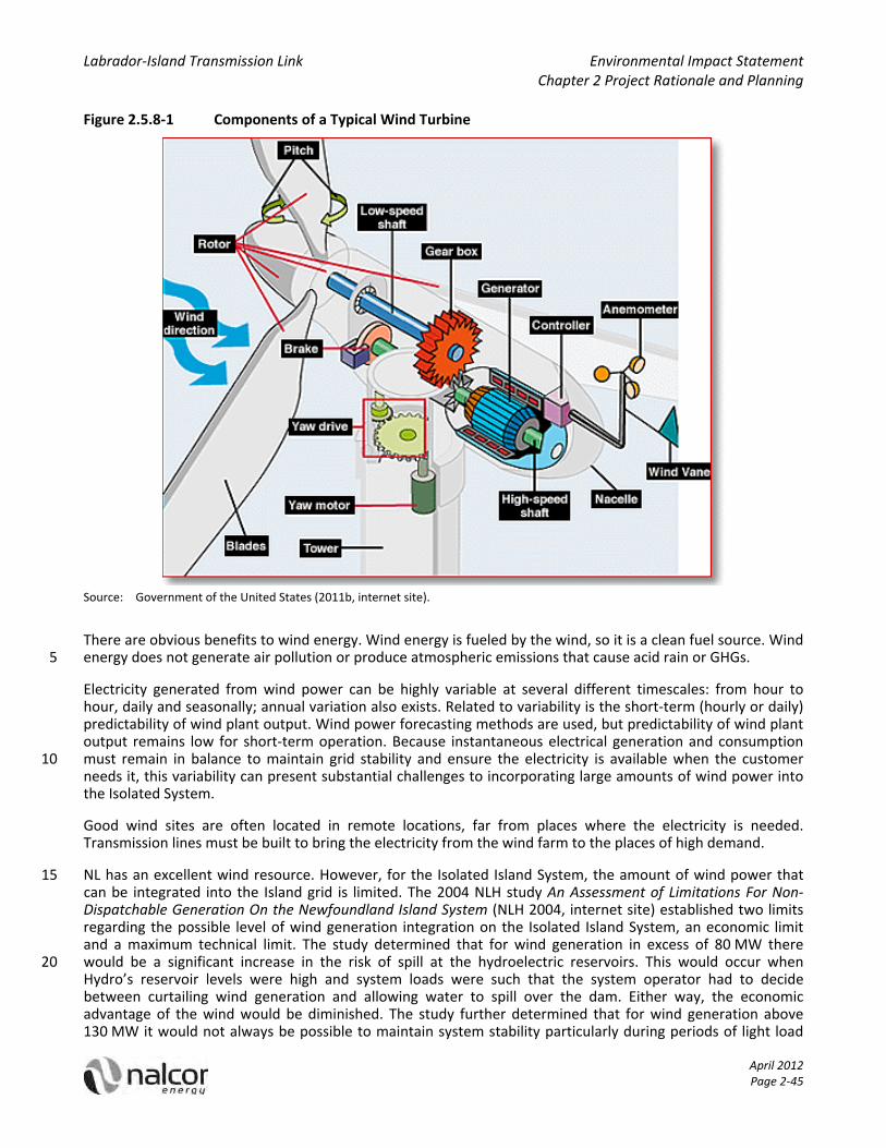
Labrador‐Island Transmission Link Environmental Impact Statement Chapter 2 Project Rationale and Planning
April 2012 Page 2‐45
Figure 2.5.8‐1 Components of a Typical Wind Turbine
Source: Government of the United States (2011b, internet site).
There are obvious benefits to wind energy. Wind energy is fueled by the wind, so it is a clean fuel source. Wind energy does not generate air pollution or produce atmospheric emissions that cause acid rain or GHGs. 5
Electricity generated from wind power can be highly variable at several different timescales: from hour to hour, daily and seasonally; annual variation also exists. Related to variability is the short‐term (hourly or daily) predictability of wind plant output. Wind power forecasting methods are used, but predictability of wind plant output remains low for short‐term operation. Because instantaneous electrical generation and consumption must remain in balance to maintain grid stability and ensure the electricity is available when the customer 10 needs it, this variability can present substantial challenges to incorporating large amounts of wind power into the Isolated System.
Good wind sites are often located in remote locations, far from places where the electricity is needed. Transmission lines must be built to bring the electricity from the wind farm to the places of high demand.
NL has an excellent wind resource. However, for the Isolated Island System, the amount of wind power that 15 can be integrated into the Island grid is limited. The 2004 NLH study An Assessment of Limitations For Non‐Dispatchable Generation On the Newfoundland Island System (NLH 2004, internet site) established two limits regarding the possible level of wind generation integration on the Isolated Island System, an economic limit and a maximum technical limit. The study determined that for wind generation in excess of 80 MW there would be a significant increase in the risk of spill at the hydroelectric reservoirs. This would occur when 20 Hydro’s reservoir levels were high and system loads were such that the system operator had to decide between curtailing wind generation and allowing water to spill over the dam. Either way, the economic advantage of the wind would be diminished. The study further determined that for wind generation above 130 MW it would not always be possible to maintain system stability particularly during periods of light load

Labrador‐Island Transmission Link Environmental Impact Statement Chapter 2 Project Rationale and Planning
April 2012 Page 2‐46
and during these periods wind generation would have to be curtailed, again, reducing the economic benefit of the additional wind generation.
The limits identified in the 2004 study are still applicable today. However, as load grows, the Isolated Island System should be able to accommodate additional wind generation. It has been suggested that the system should be able to accommodate an additional 100 MW of wind in the 2025 timeframe and a further 100 MW 5 around 2035 (Navigant Consulting Ltd. 2011, internet site). NLH will study this prior to Decision Gate 3 (see Section 2.10). As well, as a result of system constraints, and recognizing the inherently intermittent nature of the wind resource, the use of a large‐scale wind farm to replace the firm continuous supply capability of the Holyrood plant is not operationally feasible and therefore was not considered in the generation expansion analysis.
NLH has not completed an analysis to establish the level of wind generation that could be sustained in the 10 Muskrat Falls and Labrador‐Island Transmission Link option. However, given that this option will include at least one interconnection to the North American electrical grid, and that there will be considerable hydroelectric capacity both in Labrador and on the Island to provide backup, it would be reasonable to consider the addition of up to 400 MW of wind generation on the system.
Onshore wind power typically costs 8 to 12 ¢/kWh, depending largely on how windy the site is and how far it is 15 from existing power transmission lines (The Pembina Institute. n.d). Good wind sites on the Island are at the lower end of this cost range. The estimated average cost incorporates the cost of construction of the turbine and transmission facilities, borrowed funds, return to investors (including cost of risk), estimated annual production, and other components, averaged over the projected service life of the equipment, which is typically around twenty years. Costs associated with any bulk system transmission upgrades that may be required because of the 20 size and / or location of the wind farm are not included in the estimated generation costs.
Wind power has a place in the electricity generation mix on the Island and, due to its low environmental footprint, it will be incorporated whenever economically viable. However, technical and operational considerations limit the amount of wind generation that can be operated on the system.
2.5.9 Biomass 25
Biomass energy is derived from many different types of recently living organic matter (feedstock). However, in the context of producing large‐scale energy, it is likely that the focus would be on harvesting forestry products as fuel for the biomass generator. Biomass works similar to many other thermally‐based generators in that wood or other biomass products are harvested, treated and then transported to the generation plant to be used in place of other solid fuels such as coal to generate heat. The heat is then used to produce steam. The 30 steam is in turn fed into a turbine that turns a generator to produce electricity.
Figure 2.5.9‐1 shows how one type of biomass technology could be deployed.
Figure 2.5.9‐1 Typical Biomass Technology
Source: Government of the United States (2011c, internet site). 35

Labrador‐Island Transmission Link Environmental Impact Statement Chapter 2 Project Rationale and Planning
April 2012 Page 2‐47
One of the best advantages of biomass is the low GHG production net of the harvesting and transportation operations. Furthermore, biomass is a renewable energy source if forests are properly managed. Biomass could also provide increased markets for the province’s forestry industry as any new plants would require significant feedstock.
Biomass plants, which typically operate more efficiently at base load values can load‐follow within certain 5 ramp rates. Assuming economics, and that readily available feedstock was not a concern, a biomass plant could reasonably be integrated into the Isolated Island System.
Biomass generation requires significant and steady supplies of feedstock to support generation operations. The security of supply is critical to maintain stable generation. The National Forestry Registry has placed the province’s annual forestry harvest seventh of Canadian provinces at some 2 million cubic metres (Government 10 of Canada 2009, internet site). Therefore, significant development of this industry would be required to facilitate the addition of a biomass generator.
Generally speaking, electricity production from biomass leverages the infrastructure used to harvest forestry products for other purposes (such as lumber and pulp and paper production). The strong relationship between forestry harvest and biomass electricity production is shown in Figure 2.5.9‐2 in which electricity produced 15 from wood and spent pulping liquor (vertical axis) is plotted against annual forestry harvest (horizontal axis) for nine provinces.
Figure 2.5.9‐2 Electricity Production from Wood and Spent Pulping Liquor versus Forestry Harvest by Province
20 Source: Government of Canada (2009, internet site); Statistics Canada (2009).
As shown, British Columbia has both the highest forestry harvest and the highest volume of electricity produced from wood and spent pulping liquor. Not all of the provinces fall on the line shown in the figure, but there is clearly a relationship between electricity produced from wood, and spent pulping liquor and forestry harvest. 25
Based on this relationship and NL’s annual forestry harvest, it is estimated that the province may have capacity for electricity produced from wood and spent pulping liquor in the range of perhaps 100 GWh by leveraging

Labrador‐Island Transmission Link Environmental Impact Statement Chapter 2 Project Rationale and Planning
April 2012 Page 2‐48
the existing infrastructure. This estimate is not the upper limit of electricity production; the province certainly has large areas of forest, but the infrastructure (access roads, vehicles and skilled labour) to harvest sufficient biomass to produce more than the estimated 100 GWh does not likely exist. As a result, higher levels of production are likely to require higher levels of infrastructure investment that ultimately result in higher biomass (and electricity) costs. 5
Due to the requirement to harvest a large and steady supply of forestry products, manage and maintain the sustainability of the forest harvest, and transportation costs in getting the harvested material to the generation site, the unit costs for energy from biomass plants is usually much higher than other forms of energy.
Navigant Consulting Ltd. has worked with several recent biomass projects and has determined that the capital 10 cost of a new biomass facility is about $3,500 per kilowatt (kW) and the variable fuel cost would be on the order of $50‐$100 per MWh giving a unit cost of about $150‐$200 per MWh in the province (Navigant Consulting Ltd. 2011, internet site).
While biomass and other co‐generation alternatives, when economically feasible, will be considered as future supply alternatives, they are not considered to be appropriate replacements for large‐scale generation 15 requirements due to the significant costs and risks around securing an adequate supply of feedstock. On this basis, biomass was screened out as an Isolated Island supply alternative.
2.5.10 Solar Energy
Solar power is the conversion of sunlight into electricity. This is carried out by two main methods:
1. Using sunlight indirectly, Concentrating Solar Power systems use lenses or mirrors and tracking systems to 20 focus a large area of sunlight into a small beam to boil water which is then used to provide power.
2. Using sunlight directly, a solar cell, or photovoltaic (PV) cell, is a device that converts light into electric current using the photoelectric effect. Currently in Canada, solar power is focused primarily on PVs.
Photovoltaic (SunEdison 2011, internet site) literally means “light” and “electric.” PV technologies are used to generate solar electricity by using solar cells packaged in PV modules. 25
The most important components of a PV cell are the two layers of semiconductor material. When sunlight strikes the PV cell, the solar energy excites electrons that generate an electric voltage and current. Extremely thin wires running along the top layer of the PV cell carry these electrons to an electrical circuit.
A PV module is made of an assembly of PV cells wired in series to produce a desired voltage and current. The PV cells are encapsulated within glass and / or plastic to provide protection from the weather. PV modules are 30 connected together to form an array. The array is connected to an inverter which converts the direct current (dc) of the PV modules to alternating current (ac). A typical solar cell array is illustrated in Figure 2.5.10‐1.

Labrador‐Island Transmission Link Environmental Impact Statement Chapter 2 Project Rationale and Planning
April 2012 Page 2‐49
Figure 2.5.10‐1 Solar Cell Array
Source: Stock Photo.
There are a number of issues with using solar power as a generation source on the Island System:
1. Solar power is non‐dispatchable; when the sun shines, the system has to take the power generated and 5 when the sun is not shining, during the night, or during cloudy periods, other forms of generation have to be available for backup. The issues with non‐dispatchability have been / will be discussed in the sections on “Wind” and “Other Small Hydro”.
2. NLH’s peak demand period typically occurs in the winter during the supper hour. At that time, output from solar power will be nil. Thus, solar power will not provide any capacity at the time of peak demand. 10
3. NL has one of the lowest rates of solar insolation in Canada, which would result in a low capacity factor and higher unit costs. Even in areas where solar insolation is highest, unit costs for commercial solar energy production are amongst the highest of all generation sources.
According to Natural Resources Canada’s (NRCan 2011, internet site), their PV potential and insolation maps indicate that Newfoundland has the second lowest PV potential (kWh/kW) in Canada, as compared to all other 15 provinces.
Figure 2.5.10‐2 shows NL’s PV potential in relation to the rest of Canada.
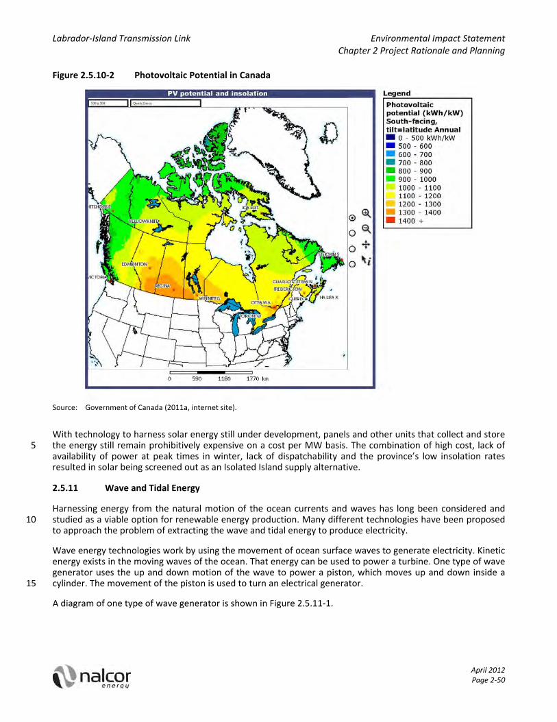
Labrador‐Island Transmission Link Environmental Impact Statement Chapter 2 Project Rationale and Planning
April 2012 Page 2‐50
Figure 2.5.10‐2 Photovoltaic Potential in Canada
Source: Government of Canada (2011a, internet site).
With technology to harness solar energy still under development, panels and other units that collect and store the energy still remain prohibitively expensive on a cost per MW basis. The combination of high cost, lack of 5 availability of power at peak times in winter, lack of dispatchability and the province’s low insolation rates resulted in solar being screened out as an Isolated Island supply alternative.
2.5.11 Wave and Tidal Energy
Harnessing energy from the natural motion of the ocean currents and waves has long been considered and studied as a viable option for renewable energy production. Many different technologies have been proposed 10 to approach the problem of extracting the wave and tidal energy to produce electricity.
Wave energy technologies work by using the movement of ocean surface waves to generate electricity. Kinetic energy exists in the moving waves of the ocean. That energy can be used to power a turbine. One type of wave generator uses the up and down motion of the wave to power a piston, which moves up and down inside a cylinder. The movement of the piston is used to turn an electrical generator. 15
A diagram of one type of wave generator is shown in Figure 2.5.11‐1.

Labrador‐Island Transmission Link Environmental Impact Statement Chapter 2 Project Rationale and Planning
April 2012 Page 2‐51
Figure 2.5.11‐1 Example of a Wave Generator
Source: University of Bath (2011, internet site).
Tidal power is based on extracting energy from tidal movements and the water currents that accompany the rise and fall of the tide. When the tide rises, the water can be trapped in a reservoir behind a dam. Then when 5 the tide falls, the water behind the dam can be released through a turbine similar to a regular hydroelectric power plant.
Figure 2.5.11‐2 depicts one type of tidal generator. The system uses sluice gates and a barrage to trap the ocean water when it reaches its high tide level. The water is released when the tide falls, and the movement of the water is used to turn a turbine and generator to produce electricity. 10
Reinforced concrete Capture Chamber set into the excavated rock face.
The Wells Turbines rotate in the same direction regardless of the direction of the air flow. Thus generating irrespective of upward or downward movement of the water column.
Air is compressed and decompressed by the Oscillating Water Column (OWC). This causes air to be forced through the Wells Turbine and is then drawn back through the Wells Turbine.

Labrador‐Island Transmission Link Environmental Impact Statement Chapter 2 Project Rationale and Planning
April 2012 Page 2‐52
Figure 2.5.11‐2 Example of a Tidal Generator
Source: Encyclopedia Britannica (2011, internet site).
Wave and tidal energy provide a number of benefits. First, both are a clean energy source and do not emit any GHGs while generating electricity. Ocean tides are predictable and occur on a regular basis. Also, wave energy 5 is less intermittent than wind or solar power (Electric Light & Power 2009).
However, wave and tidal energy installations face some limitations. The primary limitation is the fact that the ocean environment can be harsh on the equipment used in wave and tidal installations. As a result, the equipment used must be built robustly to contend with waves and salt water. Consequently, wave and tidal generators can cost approximately three to four times more than wind turbines per megawatt (Electric Light & 10 Power 2009). Another limitation is the fact that in order for a tidal generator to work well, a large variation in tidal levels is required. This limits the locations where tidal generation can be installed to produce large amounts of electricity in an efficient manner (Ocean Energy Council 2011, internet site).
Despite some limited successes, neither tidal nor wave power has become a commercial mainstream source of renewable energy. Consequently, NLH screened out the use of wave and tidal power as an alternative supply 15 option for the Isolated Island supply alternative.
2.5.12 Hydroelectric Generation
Hydroelectric stations generate electricity using the kinetic energy of falling water. Some plants are constructed at natural drops in rivers, while others employ dams to raise the upstream water above downstream levels. Figure 2.5.12‐1 presents a diagram of a hydroelectric dam. 20
Labrador‐Island Transmission Link Environmental Impact Statement Chapter 2 Project Rationale and Planning
April 2012 Page 2‐53
Figure 2.5.12‐1 Diagram of Hydroelectric Dam
Source: Government of Canada (2011b, internet site).
Typically, a hydroelectric station generates electricity as follows:
water from a reservoir or river flows through the intake, an underwater opening into a pipe or tube called 5 the penstock;
water flows down through the penstock under increasing pressure;
at the end of the penstock, a turbine is mounted, inside a powerhouse;
as the water pushes its blades, the turbine rotates;
this turns an internal shaft connected to a generator, and electricity is produced; and 10
as the water exits the turbine, it is conducted back to the river by a channel or pipe called a tailrace.
Station capacity can be large or small and is determined by the flow rate of the water and the vertical distance between the level of the source water and the outflow – or head.
Hydroelectric generation has a number of benefits. Since hydroelectric generation converts kinetic energy from the natural water cycle into electricity, it is a renewable source that does not create smog‐ or acid rain‐15 causing atmospheric pollutants in its typical operations, or generate waste. Minimal GHGs result from normal biological processes occurring at hydro reservoirs, but life‐cycle GHG emissions are similar to those of wind power, and much lower than those of thermal combustion plants.

Labrador‐Island Transmission Link Environmental Impact Statement Chapter 2 Project Rationale and Planning
April 2012 Page 2‐54
On the economic side, although the upfront costs for constructing hydro generating stations can vary considerably and are generally high, Operations and Maintenance costs are generally low, and the lifetime of hydro plants is very long (e.g., the Petty Harbour Hydro‐Electric Generating Station near St. John’s has been generating electricity since 1900). As well, the cost of operating a hydroelectric plant is nearly immune to increases in the cost of fossil fuels such as oil, natural gas or coal, and no imports are required. 5
In addition, hydro is a very reliable and predictable source of power. As a result of the longevity, reliability and flexibility of hydroelectric stations in Canada, hydro is one of the cheapest sources of electricity. According to the National Energy Board, Canada’s reliance on hydroelectric generation is largely responsible for the country having some of the lowest electricity prices in the world (National Energy Board 2011, internet site).
NLH carries three hydro developments on the Island in its generation portfolio for potential development. 10 These projects have been screened and evaluated to be both economically viable and environmentally acceptable. Therefore, NLH has undertaken feasibility studies for the following three hydroelectric sites in its portfolio (SNC‐Lavalin Inc. 1988, 1989, 2006, 2007), all of which are applicable in both generation expansion alternatives and progressed to phase 2 screening.
2.5.12.1 Island Pond 15
Island Pond is a proposed 36 MW hydroelectric project located on the North Salmon River, within the watershed of the existing Bay d’Espoir development. The project would utilize approximately 25 m of net head between the existing Meelpaeg Reservoir and Crooked Lake to produce an annual firm and average energy capability of 172 GWh and 186 GWh, respectively.
The development would include the construction of a three kilometre (km) diversion canal between Meelpaeg 20 Reservoir and Island Pond, which would raise the water level in Island Pond to that of the Meelpaeg Reservoir. Also, approximately 3.4 km of channel improvements would be constructed in the area. At the south end of Island Pond, a 750 m long forebay would pass water to the 23 m high earth dam, and then onto the intake and powerhouse finally discharging it into Crooked Lake via a 550 m long tailrace. The electricity would be produced by one 36 MW Kaplan turbine and generator assembly. 25
The facility would be connected to TL 263, a nearby 230 kV transmission line connecting the Granite Canal Generating Station with the Upper Salmon Generating Station.
A final feasibility‐level study and estimate, Studies for Island Pond Hydroelectric Project (SNC‐Lavalin Inc. 2006, internet site), was completed for NLH by an independent consultant. The report prepared a construction ready update report including an updated capital cost estimate and construction schedule projecting approximately 30 42 months from the project release date to the in‐service date. Figure 2.5.12‐2 illustrates the conceptual sketch of the Island Pond development.
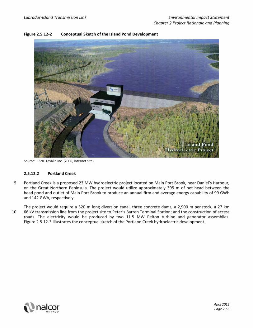
Labrador‐Island Transmission Link Environmental Impact Statement Chapter 2 Project Rationale and Planning
April 2012 Page 2‐55
Figure 2.5.12‐2 Conceptual Sketch of the Island Pond Development
Source: SNC‐Lavalin Inc. (2006, internet site).
2.5.12.2 Portland Creek
Portland Creek is a proposed 23 MW hydroelectric project located on Main Port Brook, near Daniel’s Harbour, 5 on the Great Northern Peninsula. The project would utilize approximately 395 m of net head between the head pond and outlet of Main Port Brook to produce an annual firm and average energy capability of 99 GWh and 142 GWh, respectively.
The project would require a 320 m long diversion canal, three concrete dams, a 2,900 m penstock, a 27 km 66 kV transmission line from the project site to Peter’s Barren Terminal Station; and the construction of access 10 roads. The electricity would be produced by two 11.5 MW Pelton turbine and generator assemblies. Figure 2.5.12‐3 illustrates the conceptual sketch of the Portland Creek hydroelectric development.

Labrador‐Island Transmission Link Environmental Impact Statement Chapter 2 Project Rationale and Planning
April 2012 Page 2‐56
Figure 2.5.12‐3 Conceptual Sketch of the Portland Creek Hydroelectric Development
Source: Nalcor (2011a, internet site).
The current schedule and capital cost estimate for Portland Creek is based on a January 2007 feasibility study, Feasibility Study for: Portland Creek Hydroelectric Project (SNC‐Lavalin Inc. 2007, internet site), prepared for 5 NLH by an independent consultant. The proposed construction schedule indicates a construction period of 32 months from the project release date to the in‐service date.
2.5.12.3 Round Pond
Round Pond is a proposed 18 MW hydroelectric project located within the watershed of the existing Bay d’Espoir development. The project would utilize the available net head between the existing Godaleich Pond 10 and Long Pond Reservoir to produce an annual firm and average energy capability of 108 GWh and 139 GWh, respectively.
The current schedule and capital cost estimate for Round Pond is based on the 1988 feasibility study, Round Pond Hydroelectric Development (SNC‐Lavalin Inc. 1988, 1989, internet site), prepared for NLH by an independent consultant, and the associated 1989 Summary Report based on the same. In the absence of any 15 further work beyond what was identified in this study, the overall program for the Round Pond development is estimated to be completed in 33 months, including detailed engineering design.
2.5.12.4 Other Small Hydro
There are numerous undeveloped small hydroelectric sites on the Island. An inventory of these sites was developed in a 1986 study undertaken for NLH by Shawmont Newfoundland. The extent to which a significant 20
Labrador‐Island Transmission Link Environmental Impact Statement Chapter 2 Project Rationale and Planning
April 2012 Page 2‐57
quantity of small hydro development can be accommodated is limited because the Newfoundland electricity system is currently isolated from the North American grid. The lack of interconnection to other systems introduces technical and operational system constraints which are generally related to the ability to provide capacity when it is required during peak periods.
Most of the remaining projects do not have storage capability and are referred to as “run of the river” 5 facilities. Run of the river hydroelectric facilities have operating attributes similar to wind generators as they only operate when there is water in the river and there is no certainty that the plants will be available to provide capacity at the time of peak load.
In integrating small hydro and wind energy into the Newfoundland electricity system, planning and operational considerations to ensure reliable electricity supply are paramount. Both wind and run of the river hydro are 10 non‐dispatchable (meaning they only operate when either the wind is blowing or when there is water in the river). As discussed in Section 2.5.8, wind is quite variable, and while a run of the river project may be less variable, the fact that there is minimal or no storage means that there is no guarantee that the capacity will be available at the time of peak when it is really needed. Also, river flows during the peak winter season are often lower than during any other season. Consequently, the run of the river project has less capacity and energy 15 available when the system requires it most.
The successful integration of this technology is conditional upon an interconnection to a larger grid where there is sufficient low cost firm reserve capacity to compensate for the variability caused by the non‐dispatchability of resources (i.e., the run of the river technology). In the Isolated Island alternative the required firm reserve would be provided by the Holyrood plant or some other thermal generating source, which 20 diminishes much of the economic advantage of the non‐dispatchable resource. Since no interconnections to other markets exist, opportunities to export surplus energy to other markets or to rely on other markets to support the Island System do not exist.
Despite the concerns, there is a limited capacity for the integration of a small amount of additional non‐dispatchable resource in the Island Isolated alternative. Nalcor considered additional small hydro, but because 25 of an economic preference for wind over small hydro, Nalcor has opted to use wind as the non‐dispatchable generation of choice to be included in the Isolated Island alternative in Phase 2 screening.
Small hydro development on the Island is not without controversy and an appreciable level of public opposition. In 1992, NLH Issued a Request for Proposals (RFP) for the purchase of up to 50 MW of small hydro production from NUGs. The process involved a preliminary screening process and at the final submission stage 30 there were eleven projects submitted for consideration. The majority of these projects were for developments that had been identified in the 1986 Shawmont Newfoundland study. NLH accepted four of the eleven proposals of which two were constructed ‐ Star Lake 15 MW and Rattle Brook 4 MW. The others, Northwest River 12 MW and Southwest River 7 MW, were halted prior to construction due mainly to public opposition. Following this chain of events the GNL imposed a moratorium on further small hydro development in 1998. 35 This moratorium is still in effect today.
Since the 1998 moratorium there has been little activity around small hydro development. NLH has completed an analysis based on the 1992 RFP data that supports the decision to screen out the technology as an alternative for the Isolated Island alternative. The seven unsuccessful projects from the 1992 RFP can be considered to be representative of the most attractive of the remaining undeveloped small hydro on the 40 Island. Based on submission data, these projects had an average bid price of 6.64 cents per kWh (1992$), escalating this price to 2010$ using Nalcor’s/NLH’s “Hydraulic Plant Construction” escalation series, results in a current estimate of 10.4 cents per kWh (2010$). In comparison, NLH is carrying 9.2 cents per kWh (2010$) for the wind PPAs used in current modeling (Nalcor 2011f, internet site). This indicates that NLH would pay a premium of approximately 13% for small hydro. The estimated costs reflect single small scale installations and 45 while this would include basic grid interconnection it does not cover costs associated with major transmission upgrades that may be required for larger or multiple small scale installations.

Labrador‐Island Transmission Link Environmental Impact Statement Chapter 2 Project Rationale and Planning
April 2012 Page 2‐58
Based on these factors small hydro other than Island Pond, Portland Creek and Round Pond have been screened from further evaluation.
2.5.13 Labrador Hydroelectric Resources
2.5.13.1 Deferred Churchill Falls
In Phase 1 screening, consideration was afforded to a supply option that entailed a continuation of the 5 Holyrood plant operations and additional thermal generation as required for another three decades, and then to commission a transmission interconnection between Labrador and the Island to avail of electricity production from the Churchill Falls hydroelectric generating facility in 2041 when the current long‐term supply contract with Hydro Québec terminates. This option did not advance beyond Phase 1 screening for the following reasons (Nalcor response to MHI‐Nalcor‐3 (Nalcor 2011d, internet site)): 10
1. There is inherent uncertainty around guaranteeing the availability of supply from Churchill Falls in 2041 because it is difficult to determine the environmental and policy frameworks that will be in place 30+ years out. There are other issues surrounding the Churchill Falls asset with respect to Hydro Québec, as Nalcor is not the sole shareholder of the Churchill Falls operation.
2. There is also significant risk associated with maintaining reliable supply through continued life extension 15 measures for the Holyrood plant through to 2041. At that time, the first two units at the Holyrood plant will be 70 years old.
3. Deferral of the interconnection would result in significantly higher rates for Island consumers between now and 2041 and does not provide rate stability to Island consumers as rates are tied to highly volatile fossil fuel prices for the first 30+ years of the study period along with escalating maintenance costs for the 20 Holyrood plant and an increasing likelihood that replacement of the plant will be required prior to 2041.
4. Island customers will remain dependent on fossil fuel generation for the first 30+ years of the study resulting in continued and increasing GHG emissions. Given the Government of Canada’s decision to introduce GHG emissions regulation for coal fired generating stations, Nalcor’s ability to refurbish the Holyrood plant without conforming to GHG emissions regulation is doubtful, and replacement of the plant 25 may be required between now and 2041.
5. Each of the screening criteria above has significant risk and uncertainty that are not present in either the Isolated Island or Interconnected Island alternatives.
The prospect of requiring substantial investment to the Holyrood plant to extend its life beyond that contemplated in the Isolated Island alternative, or the real possibility of requiring replacement of the 30 Holyrood plant and then retiring it in 2041, increases the probability that this option will be substantially more expensive than projected.
The deferral of construction of Muskrat Falls and the Project introduces other economic disadvantages:
1. Value is lost by the province through the deferral of monetization of NL’s energy warehouse. The revenue benefits of Muskrat Falls, Gull Island, other wind and small hydro developments throughout the province 35 will be foregone, thus reducing government’s ability to invest in infrastructure and to provide services. Revenue that could have been used to fund long‐term assets and infrastructure will have been used to purchase imported oil.
2. Economic and employment benefits from domestic economic activity associated with domestic energy construction projects will be foregone for decades. 40
In addition, NLH completed a Strategist® analysis for a generation expansion plan that includes the deferred transmission interconnection with Labrador coupled with the supply of energy from Churchill Falls in 2041. While this option did not make it beyond Phase 1 screening, it was run in Strategist® as a sensitivity and the CPW results, which are presented in Section 2.7.1.5, confirm the decision not to pursue this option further.
Labrador‐Island Transmission Link Environmental Impact Statement Chapter 2 Project Rationale and Planning
April 2012 Page 2‐59
2.5.13.2 Recall Power from Churchill Falls
Under the existing power contract between Hydro Québec and Churchill Falls (Labrador) Corporation, there is a provision for a 300 MW block of power which can be recalled for use in Labrador. The 300 MW block is sold to NLH in its entirety. NLH meets the needs of its customers in Labrador first and then sells any surplus energy into export markets. 5
In addition to its domestic and general service customers in Labrador, NLH has contracts with:
the Iron Ore Company of Canada for 62 MW of firm power, 5 MW interruptible and secondary power if available; and
the Department of National Defense in Happy Valley‐Goose Bay for 23 MW of secondary power.
In 2010, approximately 38% of the energy available under the 300 MW recall contract was sold in Labrador, 10 with the unused balance being sold into short‐term export markets. On average in the winter almost 220 MW of power is used to meet demand in Labrador. With only 80 MW of recall power available in the winter, there is insufficient firm capacity and energy available to meet the Island’s electricity needs and to displace the Holyrood plant, which generates almost 500 MW at the time of highest (winter) need for the province. The use of recall power was therefore screened out during Phase 1 as an alternative supply option for the Island. 15
2.5.13.3 Gull Island
Gull Island is a 2,250 MW hydroelectric generation project on the Churchill River with an average annual energy capability of 11.9 TWh. Located 225 km downstream from the existing Churchill Falls power plant, Gull Island has been extensively studied over the years and the engineering work completed has led to a high level of confidence in the planned design and optimization of the facility. 20
Gull Island is the larger of the two Lower Churchill hydroelectric sites. While offering more favourable economies of scale than Muskrat Falls, and therefore a lower unit cost per MWh of production, if all of the output was assumed sold or used, Gull Island requires significantly greater capital investment. The scale of Gull Island output creates a requirement to either negotiate with neighbouring utilities for export contracts, attract investments in energy intensive industries, or to participate directly in regional wholesale markets to attain the 25 full utilization unit cost. If such opportunities do not exist, and Island supply is the only available market, then the total cost for Gull Island has to be spread over a smaller block of utilized energy. This makes the actual unit cost of Gull Island greater than Muskrat Falls.
Figure 2.5.13‐1 shows the forecasted energy requirement for the Island against the annual output for Gull Island. Initially, the Island would require less than 20% of Gull Island’s annual production, growing to about 30 45% by 2065. The development of Gull Island is therefore linked to either the successful negotiation of both power sales agreements and transmission service arrangements for exports, or a significant increase in industrial load in the province, or a combination of both. Because of the magnitude of the investment associated with Gull Island, compared to that of Muskrat Falls, greater certainty is required for these arrangements in advance of sanctioning the project to meet the requirements of potential lenders to the 35 project.

Labrador‐Island Transmission Link Environmental Impact Statement Chapter 2 Project Rationale and Planning
April 2012 Page 2‐60
Figure 2.5.13‐1 Island‐Labrador Electricity Supply Balance with Gull Island
Source: Exhibit 6B (Nalcor 2010e, internet site).
Historically there were no open transmission services available in Canada. Labrador hydroelectric potential was geographically isolated from larger power markets with the exception of Québec. Over the past many years 5 there have been a number of unsuccessful efforts to negotiate power sales arrangements with Hydro Québec and to attract energy intensive industry to the province, especially aluminum smelting.
The unbundling of the electricity industry into its primary services, and introduction of wholesale competition in United States of America electricity markets in the latter 1990s, required the adoption of open non‐discriminatory transmission access to facilitate competition in the industry. The US Federal Energy Regulatory 10 Commission (US FERC), which has jurisdiction over the US wholesale electricity trade, has adopted multiple rules designed to prevent undue discrimination and the exercise of market power to ensure fair and competitive markets. All market participants owning transmission facilities have to conform to these rules and must demonstrate they are providing open non‐discriminatory transmission access to third parties. The adoption of open access transmission tariffs marked a milestone change for the electricity sector. Hydro 15 Québec is now required to provide open transmission access on its transmission grid in return for being able to participate in the wholesale electricity market in the northeast US. While there is no Canadian federal regulator with jurisdiction to ensure open and fair access over all transmission in Canada, the US FERC does have jurisdiction over the US activities of Canadian entities that participate in US competitive wholesale markets. 20
NLH, and subsequently Nalcor, have followed these market developments closely. In 2006, NLH made an application to Hydro Québec for transmission service for output from the Lower Churchill Project to multiple markets in accordance with open access rules. This started a multi‐stage study process that, ultimately would normally have led to a transmission service agreement. NLH was not satisfied that Hydro Québec was adhering to its own open access rules and procedures and filed formal complaints with the Québec Energy Regulator, 25 (the Regie de l’energie (the Regie)). This led to a prolonged regulatory complaint hearing process that culminated in decisions against NLH. In 2010, NLH sought a revision of the Regie’s decisions on grounds that
Labrador‐Island Transmission Link Environmental Impact Statement Chapter 2 Project Rationale and Planning
April 2012 Page 2‐61
they contained fundamental errors. In 2011, this application was denied. NLH subsequently has filed an application for judicial review by the Québec Superior Court of the Regie’s decisions on grounds that the Regie committed fundamental errors in terms of procedure and in the application of Hydro Quebec’s open access rules.
NLH has invested significant time and resources in PPA negotiations and in seeking transmission access in 5 accordance with open access rules on the Hydro Québec transmission system. Nalcor will continue to avail of all appropriate channels to obtain the firm transmission services required to develop an export sales portfolio for the Gull Island project. However, in the absence of the required certainty on being able to access export markets and sell surplus production, it would not be prudent at this time to propose project sanction for the Gull Island project. Similarly, in the absence of substantive commitments from new or existing industrial 10 interests requiring major new power and energy requirements, it is again not prudent for Nalcor to advance Gull Island further at this time.
Because of the large scale of production and investment associated with the Gull Island development, firm transmission access to export markets is required since the internal provincial requirements account for a relatively small percentage of the output for many years. In the absence of such firm transmission service, 15 reasonable financing of Gull Island would be unlikely.
As a result of the high unit cost of energy without external sales or other new use compared to Muskrat Falls, the absence of firm transmission access to export markets at this time and the difficulty of arranging financing in such an environment, Gull Island did not advance past the Phase 1 screening of alternatives.
2.5.13.4 Muskrat Falls 20
The hydroelectric generation site at Muskrat Falls near the Churchill River is an 824 MW facility with an average energy capability of 4.9 TWh per year.
Figure 2.5.13‐2 provides the forecast requirements for the Island Relative to the output of Muskrat Falls across the planning period. The Island can initially use about 40% of Muskrat Falls supply in the early years following commissioning, increasing steadily in line with the Island’s economic growth and so that by the mid 2050s, 25 100% of the Muskrat Falls production would be used within the province.

Labrador‐Island Transmission Link Environmental Impact Statement Chapter 2 Project Rationale and Planning
April 2012 Page 2‐62
Figure 2.5.13‐2 Island‐Labrador Electricity Supply Balance with Muskrat Falls
Source: Exhibit 6B (Nalcor 2010e, internet site).
As noted in the previous Gull Island section, the unit cost of Muskrat Falls, assuming no value for the unutilized energy, is lower than the Gull Island unit cost under the same assumption. Muskrat Falls offers an 5 appropriately sized indigenous and renewable generation project to address the internal energy requirements for the province in the foreseeable future. Surpluses in the initial years can be used for additional local requirements or sold, as possible, into short term export markets. The Muskrat Falls supply option cleared Phase 1 screening for input to further system planning analysis.
2.5.14 Regional Imports 10
As an alternative to the development of indigenous resources and facilities, NLH could construct a transmission interconnection to regional electricity markets and to then import its power and energy requirement to displace thermal production at the Holyrood plant and meet the incremental growth in electricity demand for the province. Two configurations were considered for Phase 1 screening in this regard:
a transmission interconnection from Churchill Falls to the Island; and 15
a transmission interconnection from the Maritimes to the Island.
For purposes of the screening review, energy was assumed to be ultimately sourced from the New York and New England markets as both regions have competitive wholesale generation markets.
Unrestricted access to firm transmission services were assumed to be available across intervening jurisdictions of Québec and New Brunswick / Nova Scotia, respectively. Accordingly, the extent of transmission system 20 reinforcements that may be required, for example, across Nova Scotia and New Brunswick is unknown, and could not be determined for the screening review. The prevailing assumption was that the existing Open Access Transmission Tariffs for Nova Scotia and New Brunswick, or for Québec, would be the only external transmission expenses to apply.

Labrador‐Island Transmission Link Environmental Impact Statement Chapter 2 Project Rationale and Planning
April 2012 Page 2‐63
Each HVdc interconnection configuration would terminate at Soldiers Pond, adjacent to the Avalon load centre, consistent with the Labrador‐Island Transmission Link. As load on the Island grows, increasing firm transmission capacity would be required.
Reliance on electricity imports raised the following considerations in Phase 1 screening:
exposure to price volatility or significant price premiums; 5
security of supply – short‐ and long‐term; and
potential market structural / transmission impediments.
2.5.14.1 Price Volatility
Natural gas‐fired generation is typically the marginal supply source and price setter in both the New York and New England wholesale generation markets, as is evident in Figure 2.5.14‐1 and Figure 2.5.14‐2. 10
Figure 2.5.14‐1 Annual Average Electricity Prices and Natural Gas Prices in New York State
Source: New York Independent System Operator (2011).

Labrador‐Island Transmission Link Environmental Impact Statement Chapter 2 Project Rationale and Planning
April 2012 Page 2‐64
Figure 2.5.14‐2 All in Cost of Electricity in New England and Natural Gas Prices in New England
Source: ISO New England (2011a).
As a result of the strong correlation between electricity market clearing prices and natural gas prices, these wholesale market prices are exposed to gas price volatility. In addition to gas price volatility, many other local 5 variables affect the short‐term clearing prices in these markets, including weather conditions impacting peak demand, unplanned generation or transmission outages and transmission congestion.
2.5.14.2 Security of Supply
Security of supply is continuously assessed by the System Operators in these regions. The latest market reports (ISO New England 2011b, internet site; New York Independent System Operator 2011) indicate that the 10 economic recession has had a significant impact on load in the region, thus providing short term assurance of the adequacy of supply to meet forecast market requirements. However, beyond 2015, both New England and New York are facing potentially significant plant retirements, both because of the age of the generation fleet and because a significant proportion of the baseload generators in the region are carbon fuelled (coal and gas in particular). In New York, 60% of installed generation is pre 1980s generation (New York Independent System 15 Operator 2011) and 53% of capacity is oil‐ or coal‐fired (New York Independent System Operator 2011). The New York Independent System Operator predicts that almost 24,000 MW of generation capacity will be impacted by the more stringent Environmental Protection Agency regulations. As a result of the required expenditures to achieve compliance, certain older facilities may be no longer competitive and forced to close. In New England, coal and oil generation comprise 9,604 MW or 30% of generation capacity. The New England 20 system operator reports estimates for retirements or de‐ratings in the range of 5,800 MW to 8,700 MW resulting from Environmental Protection Agency rules (ISO New England 2011b, internet site).
Plant retirements and / or de‐rating across the region have implications for the availability and price of supply and are risks which are introduced as a result of relying on imports as a long‐term supply source for the province. 25

Labrador‐Island Transmission Link Environmental Impact Statement Chapter 2 Project Rationale and Planning
April 2012 Page 2‐65
2.5.14.3 Potential Market Structural and Transmission Impediments
While reliance on imports reduces control over security of supply, some of this may also be a result of how electricity markets are structured and function. For example in the New England and New York markets there are currently no long‐term physical transmission rights (beyond 1 to 2 years), thereby complicating the process of transmitting energy from a power plant in the market to an external customer. While the System Operators 5 are working on addressing this issue it is currently a consideration.
In summary, as a result of the risks outlined on price volatility, security of long‐term supply, and transmission impediments, the reliance on electricity imports as a long‐term supply option for the Island was not considered further following Phase 1 screening.
2.5.15 Summary of Supply Alternatives 10
Table 2.5.15‐1 summarizes the power supply options considered by NLH in its assessment of long‐term generation expansion alternatives for the future supply of power and energy for the province in general and for the Island in particular.
Table 2.5.15‐1 Summary of Power Generation Supply Options and Initial Screening
Power Generation Option Isolated Island Interconnected Island
Nuclear
Natural Gas
Liquefied Natural Gas
Coal
Combustion Turbines
Combined Cycle Combustion Turbines
Wind
Biomass
Solar
Wave/Tidal
Island Hydroelectric
Labrador Hydroelectric n/a
Electricity Imports n/a
Transmission Interconnection n/a
Source: Nalcor (2011a, internet site). 15
As previously stated, NLH applied a high level of scrutiny to the screening around security of supply and reliability and this level of scrutiny is deemed necessary because NLH has to demonstrate with confidence that it can fulfill its mandate. The generation supply options that passed the initial screening were included in the portfolio of options that the Strategist® utility power system planning software optimized for the least‐cost objective function subject to certain constraints like the presence or absence of resources associated with the 20 Lower Churchill Project.
With the screening process completed, the alternatives that pass the screening process are then optimized into a least‐cost generation expansion for an Interconnected Island (Project) and Isolated Island (no Project) alternative.

Labrador‐Island Transmission Link Environmental Impact Statement Chapter 2 Project Rationale and Planning
April 2012 Page 2‐66
2.6 Development of Least‐Cost Generation Expansion Plans
The next step in the economic evaluation process is to develop least‐cost generation expansion plans under two scenarios – without the Project (Isolated Island alternative) and with the Project (Interconnected Island alternative). Strategist® is used to develop an optimized least‐cost solution in each scenario using the supply options that have advanced through the initial screening process. Applicable generation and transmission 5 planning criteria are adhered to in all cases.
2.6.1 Isolated Island (No Project) Alternative
The Isolated Island alternative is an optimization of proven technologies and supply options that passed through the initial screening and that have been engineered to a level sufficient to ensure they can meet the required expectations from reliability, environmental and operational perspectives. There is a high level of 10 certainty that all elements can be permitted, constructed and integrated successfully with existing operations.
The Isolated Island alternative is a least‐cost optimization of all costs associated with the development of further Island hydroelectric facilities, additional wind supply, and a combination of replacement capital for existing thermal facilities and the construction of new thermal resources utilizing fossil fuels purchased in global oil markets. Important capital and operating components of the Isolated Island alternative rest with 15 pollution abatement technologies for the Holyrood plant as well as the subsequent installation of CCCT technology utilizing light fuel oil for growth as well as for the replacement of the Holyrood plant.
The generation expansion plan for the Isolated Island alternative is a continuation of the status quo that relies on the continued operation of the Holyrood plant. In addition, the generation alternatives available from those not screened are available for inclusion in the expansion plan. These include: 20
a. Small hydroelectric developments, and more specifically, Portland Creek, Island Pond, and Round Pond.
b. Wind generation limited to be within existing economic constraints.
c. CTs.
d. CCCTs.
The Isolated Island alternative represents the No‐Project alternative, as the Island remains isolated from the 25 rest of the North American electricity grid. It also represents the optimum portfolio of available generation sources without the Project.
The Strategist® software was used to develop the least‐cost Isolated Island expansion plan. The system additions are listed in Table 2.6.1‐1 and have been characterized as generation planning criteria‐driven investments versus life extension and replacement capital. 30
The Isolated Island expansion plan includes multiple capital expenditures driven by the planning criteria mostly due to load growth. These include the addition of the 36 MW Island Pond and 18 MW Round Pond which benefit from the reservoir storage available through the existing Bay d’Espoir system. These facilities offer firm capacity which is beneficial for the Isolated Island generation expansion plan. As well, the 23 MW Portland Creek plant on the Northern Peninsula will produce an annual firm and average energy capability of 99 GWh 35 and 142 GWh, respectively. The Isolated Island alternative will also benefit from the continued operation of existing wind farms. The possibility of additional wind capacity in the Isolated Island alternative has been treated as a sensitivity analysis and is discussed further in Section 2.7.1.5. The Isolated Island expansion plan will also require significant investment to meet life extension and environmental upgrade requirements at the Holyrood plant and replacement of the existing wind farms. 40
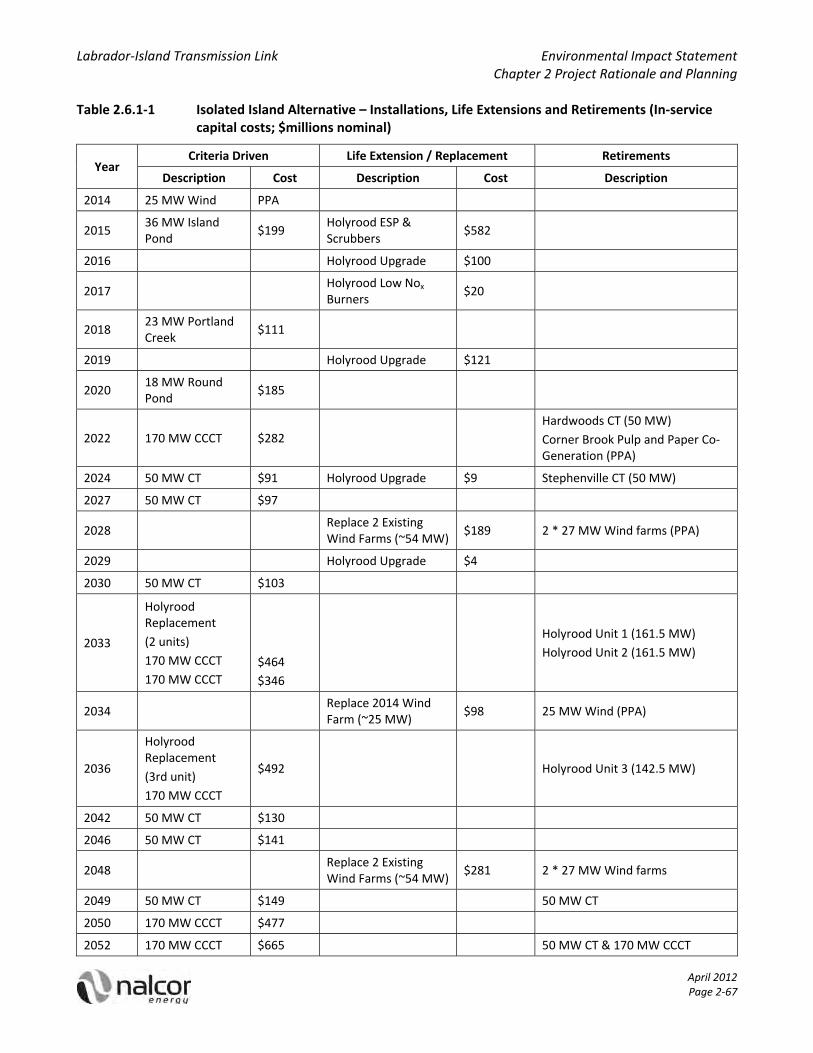
Labrador‐Island Transmission Link Environmental Impact Statement Chapter 2 Project Rationale and Planning
April 2012 Page 2‐67
Table 2.6.1‐1 Isolated Island Alternative – Installations, Life Extensions and Retirements (In‐service capital costs; $millions nominal)
Year Criteria Driven Life Extension / Replacement Retirements
Description Cost Description Cost Description
2014 25 MW Wind PPA
2015 36 MW Island Pond
$199 Holyrood ESP & Scrubbers
$582
2016 Holyrood Upgrade $100
2017 Holyrood Low Nox Burners
$20
2018 23 MW Portland Creek
$111
2019 Holyrood Upgrade $121
2020 18 MW Round Pond
$185
2022 170 MW CCCT $282
Hardwoods CT (50 MW)
Corner Brook Pulp and Paper Co‐Generation (PPA)
2024 50 MW CT $91 Holyrood Upgrade $9 Stephenville CT (50 MW)
2027 50 MW CT $97
2028 Replace 2 Existing Wind Farms (~54 MW)
$189 2 * 27 MW Wind farms (PPA)
2029 Holyrood Upgrade $4
2030 50 MW CT $103
2033
Holyrood Replacement
(2 units)
170 MW CCCT
170 MW CCCT
$464
$346
Holyrood Unit 1 (161.5 MW)
Holyrood Unit 2 (161.5 MW)
2034 Replace 2014 Wind Farm (~25 MW)
$98 25 MW Wind (PPA)
2036
Holyrood Replacement
(3rd unit)
170 MW CCCT
$492 Holyrood Unit 3 (142.5 MW)
2042 50 MW CT $130
2046 50 MW CT $141
2048 Replace 2 Existing Wind Farms (~54 MW)
$281 2 * 27 MW Wind farms
2049 50 MW CT $149 50 MW CT
2050 170 MW CCCT $477
2052 170 MW CCCT $665 50 MW CT & 170 MW CCCT
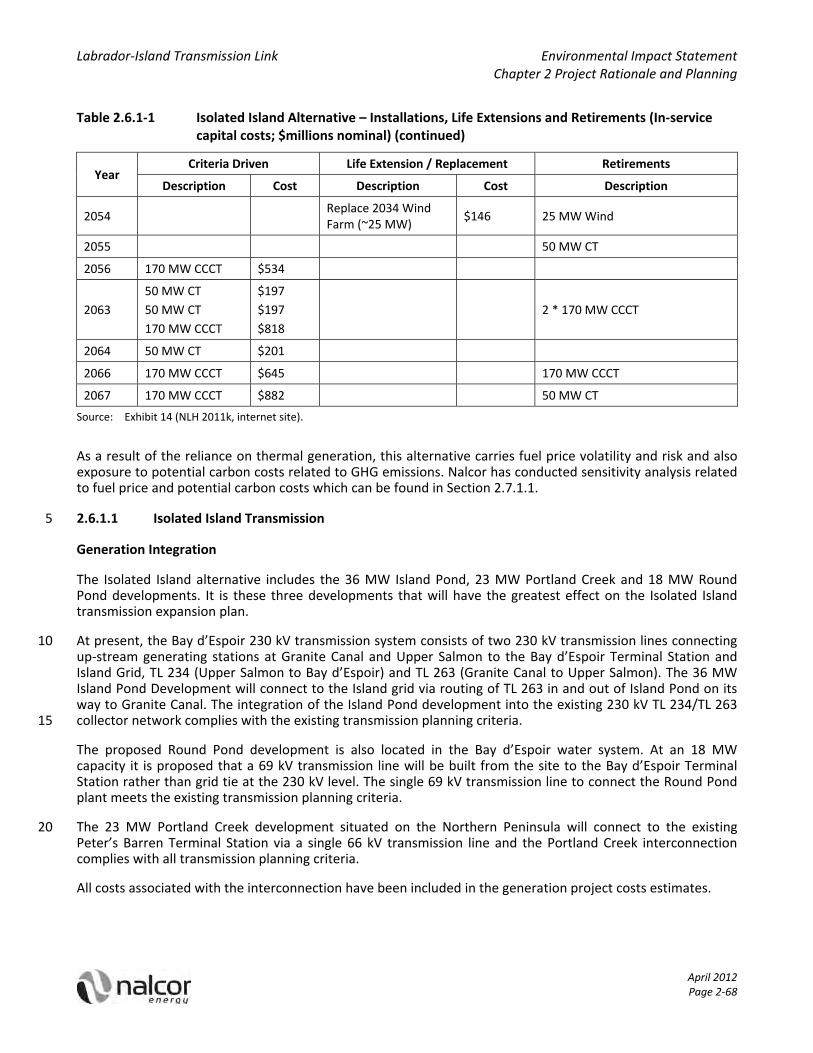
Labrador‐Island Transmission Link Environmental Impact Statement Chapter 2 Project Rationale and Planning
Table 2.6.1‐1 Isolated Island Alternative – Installations, Life Extensions and Retirements (In‐service capital costs; $millions nominal) (continued)
April 2012 Page 2‐68
Year Criteria Driven Life Extension / Replacement Retirements
Description Cost Description Cost Description
2054 Replace 2034 Wind Farm (~25 MW)
$146 25 MW Wind
2055 50 MW CT
2056 170 MW CCCT $534
2063
50 MW CT
50 MW CT
170 MW CCCT
$197
$197
$818
2 * 170 MW CCCT
2064 50 MW CT $201
2066 170 MW CCCT $645 170 MW CCCT
2067 170 MW CCCT $882 50 MW CT
Source: Exhibit 14 (NLH 2011k, internet site).
As a result of the reliance on thermal generation, this alternative carries fuel price volatility and risk and also exposure to potential carbon costs related to GHG emissions. Nalcor has conducted sensitivity analysis related to fuel price and potential carbon costs which can be found in Section 2.7.1.1.
2.6.1.1 Isolated Island Transmission 5
Generation Integration
The Isolated Island alternative includes the 36 MW Island Pond, 23 MW Portland Creek and 18 MW Round Pond developments. It is these three developments that will have the greatest effect on the Isolated Island transmission expansion plan.
At present, the Bay d’Espoir 230 kV transmission system consists of two 230 kV transmission lines connecting 10 up‐stream generating stations at Granite Canal and Upper Salmon to the Bay d’Espoir Terminal Station and Island Grid, TL 234 (Upper Salmon to Bay d’Espoir) and TL 263 (Granite Canal to Upper Salmon). The 36 MW Island Pond Development will connect to the Island grid via routing of TL 263 in and out of Island Pond on its way to Granite Canal. The integration of the Island Pond development into the existing 230 kV TL 234/TL 263 collector network complies with the existing transmission planning criteria. 15
The proposed Round Pond development is also located in the Bay d’Espoir water system. At an 18 MW capacity it is proposed that a 69 kV transmission line will be built from the site to the Bay d’Espoir Terminal Station rather than grid tie at the 230 kV level. The single 69 kV transmission line to connect the Round Pond plant meets the existing transmission planning criteria.
The 23 MW Portland Creek development situated on the Northern Peninsula will connect to the existing 20 Peter’s Barren Terminal Station via a single 66 kV transmission line and the Portland Creek interconnection complies with all transmission planning criteria.
All costs associated with the interconnection have been included in the generation project costs estimates.

Labrador‐Island Transmission Link Environmental Impact Statement Chapter 2 Project Rationale and Planning
April 2012 Page 2‐69
Bulk Transmission System
As indicated in the Island Transmission System Outlook (NLH 2010c, internet site), the 230 kV transmission system between Bay d’Espoir and the St. John’s load centre is both thermally and voltage constrained with respect to increased power transfers onto the Avalon Peninsula. In the context of the Isolated Island alternative with the hydroelectric developments at Portland Creek, Island Pond and Round Pond located in the 5 central and west portion of the Island while the load centre is located on the Avalon Peninsula, the third 230 kV transmission line from Bay d’Espoir to the Avalon Peninsula is required to increase power transfers to the load centre while meeting the transmission planning criteria. The new 230 kV transmission line will provide the necessary voltage support and thermal transfer capacity to deliver the new off‐Avalon Peninsula generation supply to the load centre. The costs associated with the new 230 kV transmission line between Bay 10 d’Espoir and the Avalon Peninsula are common to both the Isolated Island and Interconnected Island alternatives. Therefore these costs are excluded from the Strategist® analysis itself. However, such common costs are included in NLH’s total revenue requirement calculations.
2.6.1.2 Isolated Island Cumulative Present Worth
The CPW for the Isolated Island alternative is $8,810 million (2010$). This CPW value includes all of the 15 incremental operating and capital expenses associated with meeting forecastload to 2067 arising from the utility isolated expansion plan as presented in Section 2.7.1. This CPW can be partitioned according to the cost categories outlined in Table 2.6.1‐2 and Figure 2.6.1‐1.
Table 2.6.1‐2 Isolated Island Alternative: Generation Expansion Cumulative Present Worth (2010$, millions) 20
Operating and Maintenance
Fuel Existing PPAs Depreciation Return on Rate Base
Total
Isolated Island $634 $6,048 $743 $553 $831 $8,810
% of Total CPW 7.2% 68.7% 8.4% 6.3% 9.4% 100%
Source: Nalcor response to MHI‐Nalcor‐1 (Nalcor 2011d, internet site).
Figure 2.6.1‐1 Isolated Island Alternative Cumulative Present Worth Breakdown (% of total)
Source: Nalcor response to MHI‐Nalcor‐1 (Nalcor 2011d, internet site).
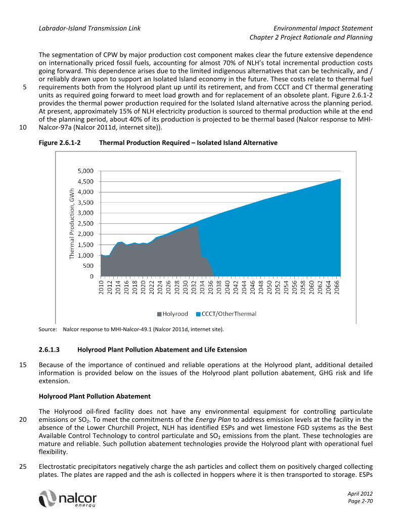
Labrador‐Island Transmission Link Environmental Impact Statement Chapter 2 Project Rationale and Planning
April 2012 Page 2‐70
The segmentation of CPW by major production cost component makes clear the future extensive dependence on internationally priced fossil fuels, accounting for almost 70% of NLH’s total incremental production costs going forward. This dependence arises due to the limited indigenous alternatives that can be technically, and / or reliably drawn upon to support an Isolated Island economy in the future. These costs relate to thermal fuel requirements both from the Holyrood plant up until its retirement, and from CCCT and CT thermal generating 5 units as required going forward to meet load growth and for replacement of an obsolete plant. Figure 2.6.1‐2 provides the thermal power production required for the Isolated Island alternative across the planning period. At present, approximately 15% of NLH electricity production is sourced to thermal production while at the end of the planning period, about 40% of its production is projected to be thermal based (Nalcor response to MHI‐Nalcor‐97a (Nalcor 2011d, internet site)). 10
Figure 2.6.1‐2 Thermal Production Required – Isolated Island Alternative
Source: Nalcor response to MHI‐Nalcor‐49.1 (Nalcor 2011d, internet site).
2.6.1.3 Holyrood Plant Pollution Abatement and Life Extension
Because of the importance of continued and reliable operations at the Holyrood plant, additional detailed 15 information is provided below on the issues of the Holyrood plant pollution abatement, GHG risk and life extension.
Holyrood Plant Pollution Abatement
The Holyrood oil‐fired facility does not have any environmental equipment for controlling particulate emissions or SO2. To meet the commitments of the Energy Plan to address emission levels at the facility in the 20 absence of the Lower Churchill Project, NLH has identified ESPs and wet limestone FGD systems as the Best Available Control Technology to control particulate and SO2 emissions from the plant. These technologies are mature and reliable. Such pollution abatement technologies provide the Holyrood plant with operational fuel flexibility.
Electrostatic precipitators negatively charge the ash particles and collect them on positively charged collecting 25 plates. The plates are rapped and the ash is collected in hoppers where it is then transported to storage. ESPs

Labrador‐Island Transmission Link Environmental Impact Statement Chapter 2 Project Rationale and Planning
April 2012 Page 2‐71
have been in application for over thirty years and are the standard for collecting fly ash from a power station’s flue gas stream. ESPs have typical collection efficiencies of 95%+ for an oil‐fired station.
NOX emissions are a function of the fuel combustion characteristics and boiler operation. The installation of the ESPs and an FGD system at the Holyrood plant would have no impact on NOX emissions at the station. For this reason, NLH has included low NOX burners to complete the scope of achievable environmental abatement 5 for the Holyrood plant.
The addition of FGD and ESP will increase station service power demand at the Holyrood plant and increase Operating and Maintenance costs. In addition, a large waste disposal facility must be developed to contain waste from FGD and ESP and there will be an increase in regional truck traffic and on‐site heavy equipment. The in‐service capital costs for the Holyrood plant’s pollution abatement program are summarized in 10 Table 2.6.1‐3.
Table 2.6.1‐3 Holyrood Pollution Abatement Capital Costs
Item In‐Service Capital Cost ($millions)
Flue Gas Desulphurization and Electrostatic Precipitators $582
Low NOx Burners $20
Total $602
Source: Exhibit 5L[i] (Stantec Consulting Ltd 2008, internet site).
These capital costs, and associated provisions for operating costs, are included in the Isolated Island generation expansion plan. It is important to note that these pollution abatement controls do not reduce GHG 15 emissions. An increase in station service load at the Holyrood plant associated with FGD operations will actually increase overall GHG emissions.
In the absence of pollution abatement and control technology at the Holyrood plant, in 2006 NLH commenced burning 1% sulphur No. 6 fuel oil to reduce emissions. This improved fuel grade reduced SO2 and other non‐GHG emissions by about 50%. In 2009, NLH improved its heavy fuel oil grade to 0.7% sulphur to reduce 20 emissions by a further 30%.
Holyrood Plant Greenhouse Gas Emissions and Production Costing Risk
GHG emissions and their effect on global warming is another prominent environmental issue. Carbon dioxide is the primary GHG of concern and the Holyrood plant emits CO2 in direct proportion to its production of thermal based electricity. The regulation of GHG could have an adverse effect on production costing and future 25 generation planning decisions.
Federal regulatory action against GHG emitting facilities is increasingly likely. There is a risk that a facility such as the Holyrood plant could not legally operate if a natural gas combined cycle benchmark for GHG emission intensity levels is applied to oil fired generation. The Government of Canada has gazetted its proposed GHG regulations for coal fired generating facilities and they tie continued operation of these facilities to meeting 30 the natural gas combined cycle benchmark (Government of Canada 2011c). Under the proposed regulations, coal facilities that are commissioned prior to July 1, 2015 and have reached the end of their 45 year design life, may receive an exemption to continue operation until 2025, provided they incorporate CCS technology to reduce their emissions intensity to that of a natural gas fired generating facility. New facilities (those commissioned on or after July 1, 2015) that incorporate CCS technology can apply for a deferral of application 35 of the standard to 2025.
Since the GHG intensity of heavy fuel oil is 77% of coal and 2.2 times higher than natural gas, NLH expects the Government of Canada will impose limitations on heavy fuel oil fired generating facilities that are similar to those proposed for coal fired generation. NLH has not completed any studies to consider the implementation

Labrador‐Island Transmission Link Environmental Impact Statement Chapter 2 Project Rationale and Planning
April 2012 Page 2‐72
of CCS at the Holyrood plant, but notes that SaskPower has initiated a $1.2 billion project to implement a CCS demonstration project on Unit 3 of SaskPower’s Boundary Dam thermal facility (SaskPower 2011). Based on these considerations, NLH believes there is a risk that the Holyrood plant will not be permitted to operate in its current manner at some point in the next 30 years until 2041.
Holyrood Operations under the Isolated lsland Alternative 5
If the Holyrood plant is required to continue operating as a base loaded thermal generating station after 2016 / 2017, which would be the circumstance in an Isolated Island supply future, extensive and comprehensive investigative work will be required to assess the cost of significantly extending the operating life of the thermal generating systems compared to other alternatives.
For the 2010 generation expansion analysis, an Isolated Island alternative assumed that the Holyrood plant 10 would continue to operate as a generating station until the mid 2030s at which time it would be retired (2033 for Units 1 and 2 and 2036 for Unit 3) and replaced with combined cycle units using LFO. NLH engineering and operating experience and expertise was used to formulate an upgrade program to see the Holyrood plant through to its targeted retirement dates. Under the Isolated Island alternative, capital upgrades included in the Strategist® analysis for the Holyrood plant total $233 million between 2011 and 2029. A breakdown of 15 upgrades required is presented in Table 2.6.1‐4
Table 2.6.1‐4 Holyrood Plant Life Extension Capital
Project In Service Year In Service Cost
($ millions)
Upgrade 1 2016 100.0
Upgrade 2 2019 121.0
Upgrade 3 2024 8.5
Upgrade 4 2029 3.6
Total 233.1
Source: Nalcor response to MHI‐Nalcor‐49.3 (Nalcor 2011d, internet site).
Isolated Island Summary
The preparation of a least‐cost generation and transmission plan for the Isolated Island alternative in Phase 2 20 results in a CPW of $8,810 million ($2010, present value). The development of indigenous renewal resources does not avoid a progressive dependence on thermal energy for the Island. Key risks for the Isolated Island alternative are world oil prices and environmental costs associated with thermal electricity generation, initially with the existing Holyrood plant, and then with CCCT plants using LFO. In the CPW analysis, no costs related to GHG emissions were included. The Holyrood plant has an additional risk regarding the extent of life extension 25 capital required so that this aging facility can reliably sustain operations until its targeted retirement dates in the early 2030s.
2.6.2 Interconnected Island (Project) Alternative
The Interconnected Island alternative is an optimization of generation alternatives primarily driven by the Muskrat Falls hydroelectric generating facility and the Labrador‐Island Transmission Link. As indicated in 30 Section 2.5.13.4, Muskrat Falls will have an installed capacity of 824 MW, and will have an average annual production of 4.9 TWh. Production from Muskrat Falls will be transmitted to the Island over the 900 MW Labrador–Island Transmission Link, which extends from the Muskrat Falls site to Soldiers Pond on the eastern Avalon Peninsula.
35

Labrador‐Island Transmission Link Environmental Impact Statement Chapter 2 Project Rationale and Planning
April 2012 Page 2‐73
With the construction and commissioning of Muskrat Falls and the Labrador–Island Transmission Link, production at the Holyrood plant will be displaced. By 2021, after Muskrat Falls and the transmission link have been successfully integrated into the Island Interconnected system, thermal production at the Holyrood plant will cease. The generators at the Holyrood plant will then operate only as synchronous condensers to provide reactive power for the HVdc converter station at Soldiers Pond and voltage support on the eastern Avalon 5 Peninsula. Post 2021, there will be no generation at the Holyrood plant under the Interconnected Island alternative.
The Interconnected Island alternative and the Muskrat Falls and the Labrador‐Island Transmission Link practically eliminates the dependence on fuel and therefore the effects and risks of fuel in the Isolated Island alternative. The exposure to GHG emissions and carbon cost is also removed. Muskrat Falls and the Labrador‐10 Island Transmission Link, however, are megaprojects and have large capital expenditures associated with them. In this regard, Nalcor has established a dedicated project team for Muskrat Falls and the transmission link, and has established a comprehensive project planning process for their development.
While the expansion plan is dominated by Muskrat Falls and the Labrador‐Island Transmission Link, the generation alternatives available from those not screened out in Section 2.5 are also available for inclusion in 15 the expansion plan. These include:
1. Small hydroelectric developments, and more specifically, Portland Creek, Island Pond and Round Pond.
2. CTs.
3. CCCTs.
It should be noted that generation additions after Muskrat Falls and the Labrador‐Island Transmission Link are 20 driven by capacity shortfalls and not by energy shortfalls.
The Strategist® software was used to develop the least‐cost interconnected expansion plan. The system additions are listed in Table 2.6.2‐1 and have been characterized as generation planning criteria‐driven investments versus life extension and replacement capital.
Table 2.6.2‐1 Interconnected Island ‐ Installations, Life Extensions and Retirements (In‐service capital 25 costs; $millions nominal)
Year Criteria Driven
Description Cost
Life Extension/ Replacement
Description
Cost Retirements
Description
2014 50 MW CT $75
2017
Holyrood Unit 1 & 2 Synchronous Condensers
900 MW Labrador Interconnection
Commencement of Supply from Muskrat Falls
$3
$2,553(a)
PPA
2021
Holyrood Unit 1 (161.5 MW)
Holyrood Unit 2 (161.5 MW)
Holyrood Unit 3 (142.5 MW)
2022
Hardwoods CT (50 MW)
Corner Brook Pulp and Paper Co‐Generation (PPA)
2024 Stephenville CT (50 MW)

Labrador‐Island Transmission Link Environmental Impact Statement Chapter 2 Project Rationale and Planning
Table 2.6.2‐1 Interconnected Island ‐ Installations, Life Extensions and Retirements (In‐service capital costs; $millions nominal) (continued)
April 2012 Page 2‐74
Year Criteria Driven
Description Cost
Life Extension/ Replacement
Description
Cost Retirements
Description
2028 2 * 27 MW Wind farms (PPA)
2036 23 MW Portland Creek $156
2037 170 MW CCCT $373
2039 50 MW CT
2046 50 MW CT $141
2050 50 MW CT $152
2054 50 MW CT $165
2058 50 MW CT $179
2063 50 MW CT $197
2066 50 MW CT $209
2067 170 MW CCCT
Source: Exhibit 14 (NLH 2010d, internet site). (a) $2.553 billion includes total capital cost of $2.073 billion plus $480 million in AFUDC.
For the purposes of balancing energy supply late in the study period, NLH has assumed that energy from Churchill Falls will be delivered to the Island at historical power contract prices. Deliveries are forecast to commence in 2057 and reach an annual delivery of approximately 500 GWh per year at the end of the study 5 period in 2067.
The Interconnected Island alternative provides access to a large energy supply. The average annual production potential at Muskrat Falls, at 4.9 TWh, is greater than the approximately 2 TWh per year forecast to be required on the Island in 2017. For the purposes of this CPW analysis, NLH has assumed that no revenue benefits would be derived from that surplus energy. Notwithstanding, approximately 60% of the production 10 from Muskrat Falls will be initially available for either short‐ term sales into export market sales or for other interconnected requirements in the province, including demands in Labrador.
Muskrat Falls will benefit from the Water Management Agreement (Nalcor and Churchill Falls (Labrador) Corporation 2009) in place between Nalcor and Churchill Falls (Labrador) Corporation. This agreement requires that the operation of Muskrat Falls be coordinated with that of Churchill Falls, and increases the ability of 15 Muskrat Falls to schedule production to meet Island needs than without a water management agreement. If the agreement were not in place, Muskrat Falls production would be limited to that available based on natural inflows and production at Churchill Falls.
Holyrood Plant Operations under the Interconnected Island Alternative
Due to the age of the Holyrood plant, and experience with unplanned unit outages caused by equipment 20 failure in recent years, NLH applied to the Board in the summer of 2009 for approval to begin Phase 1 of a condition assessment and life extension program for the plant. The Board granted partial approval to NLH to proceed and the initial work elements have now been completed with a report finalized in March of 2011.

Labrador‐Island Transmission Link Environmental Impact Statement Chapter 2 Project Rationale and Planning
April 2012 Page 2‐75
The report, prepared by the engineering consulting firm AMEC, titled Holyrood Condition Assessment and Life Extension Study 2010 (AMEC 2011, internet site) was filed with the Board on May 2nd, 2011. In summary, the condition assessment and life extension program for the Holyrood plant was based on the following operational assumptions under an Interconnected Island supply future:
1. The Holyrood plant would be required to operate as a generating station until at least the end of 2016. 5
2. The Holyrood plant would be maintained for standby power mode of operation from 2017 to 2020. To achieve this capability with a high degree of reliability, the power generation systems will be maintained as required.
3. The Holyrood plant would primarily be operated as a synchronous condensing station from 2017 into the future. 10
The scope of the AMEC Phase 1 study was to determine the basic condition of the power plant, assess its useful life, and identify components, systems or facilities which require further attention. Phase 1 also assists NLH in selecting the sampling and testing methodologies to be used in performing more detailed investigation where recommended. Within a condition assessment and life extension program, the investigative work is used to determine whether the plant is a candidate for life extension and what recommended actions will 15 achieve the extended life. The report prepared by AMEC under Phase 1 was used as a reference for planning Phase 2 of the condition assessment and life extension program. The Phase 2 study will enable NLH to identify equipment and systems that require immediate attention to operate the Holyrood plant as a generating facility safely and reliably up to 2016.
2.6.2.1 Interconnected Island Transmission 20
The Interconnected Island alternative results in the construction of a 900 MW HVdc transmission line from Labrador to the Island and the cessation of production at the Holyrood plant. With the existing 230 kV transmission system between Bay d’Espoir and the St. John’s load centre planned with the injection of 466 MW for the Holyrood plant in mind, substantial reinforcements to the 230 kV transmission system in the eastern portion of the Island would be required following removal of the 466 MW from the Holyrood plant if 25 the HVdc converter station were to be located off the Avalon Peninsula. By locating the HVdc converter station at Soldiers Pond, a location between the Holyrood plant and the St. John’s load centre where all critical 230 kV transmission lines on the Avalon Peninsula meet, NLH avoids significant construction of 230 kV ac transmission lines in the Interconnected Island alternative.
Transmission system analysis of the proposed Interconnected Island alternative has determined the system 30 reinforcements required to meet the transmission planning criteria with the HVdc converter station located at Soldiers Pond. The line commutated converter technology requires a significant quantity of reactive power to support its operation – approximately 55% of its MW rating. In addition, proper operation of the converter requires adequate system strength measured in terms of the system’s equivalent short circuit ratio (ESCR) at the ac connection point for the converter. Analysis has indicated that conversion of the Holyrood generators to 35 synchronous condensers assists in the supply of reactive power support and adequate ESCR levels. Stability analysis using PSS®E has determined that high inertia synchronous condensers and the 230 kV transmission line between Bay d’Espoir and Western Avalon are required to provide acceptable dynamic performance of the Interconnected Island alternative (NLH 2008, internet site). The additional system inertia provided by the high inertia synchronous condensers is required to maintain acceptable system frequency during system 40 disturbances that result in temporary disruptions to the HVdc system. The 230 kV transmission line between Bay d’Espoir and Western Avalon ensures angular stability of the system for short circuits close to the Soldiers Pond converter station that will result in temporary commutation failure of the converter. Short circuit analysis using PSS®E has determined the impact on short circuit levels on the system due to the increase in number of synchronous machines (Soldiers Pond synchronous condensers) and reconfiguration in transmission system 45 topology (Soldiers Pond Terminal Station and new 230 kV transmission line). The short circuit levels at a number of stations will increase to the point where existing circuit breaker interrupting rating will be exceeded. In the Interconnected Island alternative, one 230 kV circuit breaker at Bay d’Espoir, nine 230 kV

Labrador‐Island Transmission Link Environmental Impact Statement Chapter 2 Project Rationale and Planning
April 2012 Page 2‐76
circuit breakers at the Holyrood plant, and four 66 kV circuit breakers at Hardwoods, will be replaced. The costs associated with these circuit breaker replacements are included in the capital cost estimate for the Labrador‐Island Transmission Link. The costs associated with the new 230 kV transmission line between Bay d’Espoir and Western Avalon are common to both the Isolated Island and Interconnected Island alternatives. Therefore, these costs are excluded from the Strategist® analysis. However, such common costs are included 5 in NLH’s total revenue requirement calculations.
2.6.2.2 Interconnected Island Cumulative Present Worth
The CPW for the Interconnected Island alternative, which brings together the Island and Labrador power grids, combined with Muskrat Falls hydroelectric power generation located on the Lower Churchill, has a CPW of $6,652 million (2010$). This CPW includes all of the costs associated with the Muskrat Falls generation plant 10 and HVdc transmission interconnection between Labrador and the Island, as well as all other operating and capital costs attributable to the Interconnected Island generation expansion plan as presented in Section 6.1. By breaking out the Strategist® CPW into its principal cost categories the shift in cost structure and corresponding risks can be observed. The CPW detail is provided in Table 2.6.2‐2 and Figure 2.6.2‐1.
Table 2.6.2‐2 Interconnected Island Alternative: Generation Expansion Plan Cumulative Present 15 Worth (2010$, millions)
Operating and
Maintenance Fuel
Existing PPAs
Muskrat Falls PPA
Depreciation Return on Rate Base
Total
Interconnected Island
$376 $1,170 $676 $2,682 $450 $1,297 $6,652
% of Total CPW 5.7% 17.6% 10.2% 40.3% 6.8% 19.5% 100.0%
Source: Nalcor response to MHI‐Nalcor‐1 (Nalcor 2011d, internet site).
Figure 2.6.2‐1 Interconnected Island Alternative Cumulative Present Worth Breakdown (2010$, millions and % of total)
20 Source: Nalcor response to MHI‐Nalcor‐1 (Nalcor 2011d, internet site).
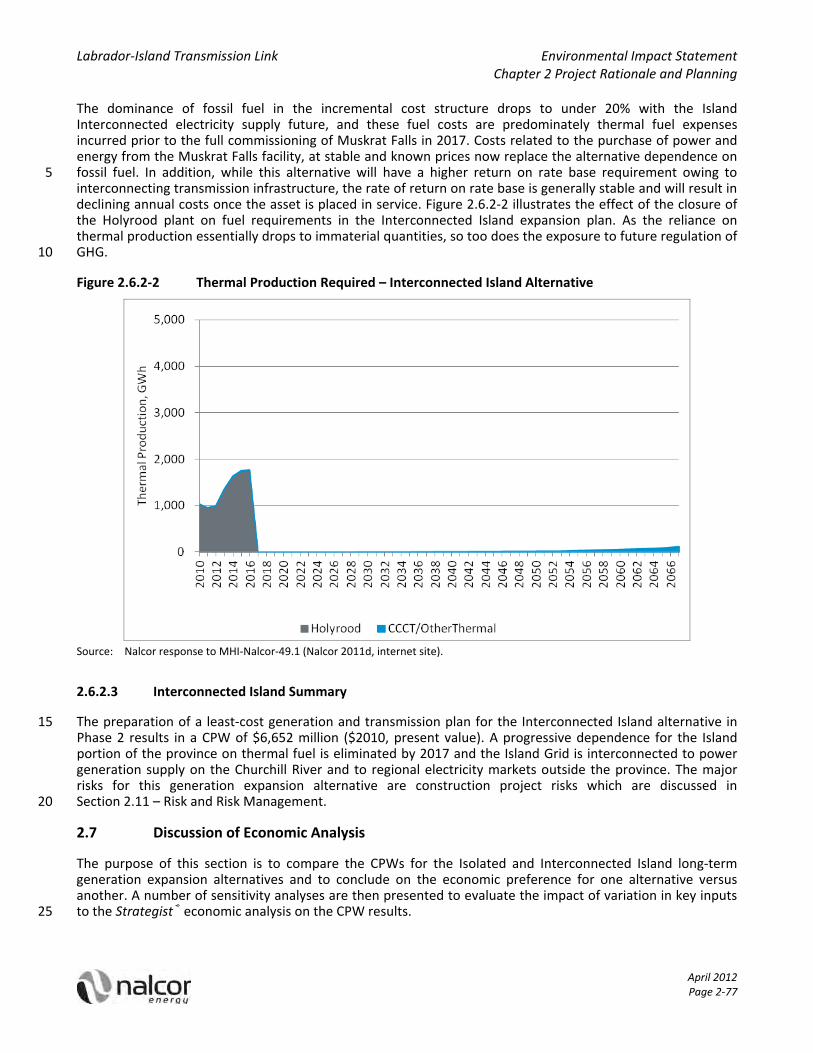
Labrador‐Island Transmission Link Environmental Impact Statement Chapter 2 Project Rationale and Planning
April 2012 Page 2‐77
The dominance of fossil fuel in the incremental cost structure drops to under 20% with the Island Interconnected electricity supply future, and these fuel costs are predominately thermal fuel expenses incurred prior to the full commissioning of Muskrat Falls in 2017. Costs related to the purchase of power and energy from the Muskrat Falls facility, at stable and known prices now replace the alternative dependence on fossil fuel. In addition, while this alternative will have a higher return on rate base requirement owing to 5 interconnecting transmission infrastructure, the rate of return on rate base is generally stable and will result in declining annual costs once the asset is placed in service. Figure 2.6.2‐2 illustrates the effect of the closure of the Holyrood plant on fuel requirements in the Interconnected Island expansion plan. As the reliance on thermal production essentially drops to immaterial quantities, so too does the exposure to future regulation of GHG. 10
Figure 2.6.2‐2 Thermal Production Required – Interconnected Island Alternative
Source: Nalcor response to MHI‐Nalcor‐49.1 (Nalcor 2011d, internet site).
2.6.2.3 Interconnected Island Summary
The preparation of a least‐cost generation and transmission plan for the Interconnected Island alternative in 15 Phase 2 results in a CPW of $6,652 million ($2010, present value). A progressive dependence for the Island portion of the province on thermal fuel is eliminated by 2017 and the Island Grid is interconnected to power generation supply on the Churchill River and to regional electricity markets outside the province. The major risks for this generation expansion alternative are construction project risks which are discussed in Section 2.11 – Risk and Risk Management. 20
2.7 Discussion of Economic Analysis
The purpose of this section is to compare the CPWs for the Isolated and Interconnected Island long‐term generation expansion alternatives and to conclude on the economic preference for one alternative versus another. A number of sensitivity analyses are then presented to evaluate the impact of variation in key inputs to the Strategist® economic analysis on the CPW results. 25

Labrador‐Island Transmission Link Environmental Impact Statement Chapter 2 Project Rationale and Planning
April 2012 Page 2‐78
The CPW for the Isolated Island alternative, at $8,810 million, compared against the CPW for the Interconnected Island alternatives, at $6,652 million, yields an economic preference for the Interconnected electricity supply alternative of $2,158 million (2010$). The change in cost structure, from a progressive dependence on international fossil fuels to one funding local power infrastructure, is achieved with the Interconnected Island alternative and at a lower long run cost for consumers (see Section 2.8 for a discussion 5 of impacts on wholesale and retail rates). The comparative CPWs for the two alternatives are summarized in Table 2.7‐1 below.
Table 2.7‐1 Comparison of Generation Expansion Alternatives: Cumulative Present Worth by Cost Component (Present Value 2010$, millions)
CPW Component Isolated Island Interconnected Island Difference
Operating and Maintenance $634 $376 ($258)
Fossil Fuels $6,048 $1,170 ($4,878)
Existing Power Purchases $743 $676 ($67)
Muskrat Falls Power Purchases n/a $2,682 $2,682
Depreciation $553 $450 ($103)
Return On Rate Base $831 $1,297 $466
Total CPW $8,810 $6,652 ($2,158)
Source: Nalcor (2011a, internet site). 10
From an economic perspective, the construction of the Project is justified based on the lower CPW compared to the alternative of not constructing the Project and going forward with the Isolated Island generation expansion plan. As illustrated in Table 2.7‐1, the primary source of the difference in CPW that results in the preference for the Interconnected Island alternative is the difference between the cost of fuel in the Isolated Island alternative and the cost of the Muskrat Falls PPA. 15
2.7.1 Sensitivity Analysis
The generation expansion CPW analysis for the Island grid has numerous input and economic and financial levers. A sensitivity analysis, wherein the value for a key input variable is increased or decreased to determine its effect on a reference case result, provides useful information concerning the robustness of the analytical results and investment preferences arising therefrom. During the course of the analysis, a number of 20 sensitivities have been prepared. These sensitivities were related to fuel costs (including carbon costs), capital costs, load forecasting, the importation of energy from the Upper Churchill in 2041 and other variables.
2.7.1.1 Fuel Costs and Carbon Pricing
Table 2.7.1‐1 below illustrates the results of the sensitivity analyses regarding fuel price forecasts using various fuel price scenarios as well as a sensitivity analysis on the effects of carbon pricing. 25

Labrador‐Island Transmission Link Environmental Impact Statement Chapter 2 Project Rationale and Planning
April 2012 Page 2‐79
Table 2.7.1‐1 Fuel Price Sensitivity Analysis (Cumulative Present Worth 2010$, millions)
Isolated Island Interconnected Island Preference for
Interconnected Island
Reference Case $8,810 $6,652 ($2,158)
PIRA High World Oil Forecast $12,822 $7,348 ($5,474)
PIRA Low World Oil Forecast $6,221 $6,100 ($120)
PIRA May 2011 Update For Reference Oil Price Forecast
$9,695 $6,889 ($2,806)
Carbon Pricing on Fossil Fuel $9,324 $6,669 ($2,655)
Source: Nalcor (2011a, internet site).
2.7.1.2 Capital Costs
Table 2.7.1‐2 illustrates the results of the sensitivity analyses regarding the capital cost estimate where capital costs are increased by 25% and 50%. 5
Table 2.7.1‐2 Capital Cost Sensitivity Analysis (Cumulative Present Worth 2010$, millions)
Isolated Island Interconnected Island Preference for
Interconnected Island
Reference Case $8,810 $6,652 ($2,158)
Muskrat Falls and Labrador‐Island Transmission Link Capital Cost +25%
$8,810 $7,627 ($1,183)
Muskrat Falls and Labrador‐Island Transmission Link Capital Cost +50%
$8,810 $8,616 ($194)
Source: Nalcor (2011a, internet site).
2.7.1.3 Load Forecasting and Conservation and Demand Management
Other important variables affecting the economic analysis are the load forecasting assumptions and the use of CDM. Table 2.7.1‐3 provides the results of several sensitivity analyses relevant to load forecasting. 10
Table 2.7.1‐3 Summary of Cumulative Present Worth Sensitivity Analysis for Load Forecasting and Conservation and Demand Management with Respect to Reference Case and Preference (Present Value 2010$, millions)
Isolated Island Interconnected
Island Preference for
Interconnected Island
Reference Case $8,810 $6,652 ($2,158)
Moderate Conservation (375 GWh/yr by 2031) $8,363 $6,652 ($1,711)
Aggressive Conservation (750 GWh/yr by 2031) $7,935 $6,652 ($1,283)
Loss of 880 GWh/yr 2013 Forward $6,625 $6,217 ($408)
Loss of 1086 GWh/yr 2013 Forward $6,121 $6,121 $1(a)
Low Load Growth (50% of 2010 PLF post Vale) $7,380 $6,618 ($763)
Source: Nalcor (2011a, internet site). (a) Difference due to rounding. 15

Labrador‐Island Transmission Link Environmental Impact Statement Chapter 2 Project Rationale and Planning
April 2012 Page 2‐80
2.7.1.4 Churchill Falls Deferred Link
The generation expansion alternative of continuing to maintain operations on the Isolated Island grid until the expiry of the Churchill Falls contract and the deferred construction of the Labrador‐Island Transmission Link was also analysed within Strategist®. The results of this analysis are summarized in Table 2.7.1‐4.
Table 2.7.1‐4 Summary of Cumulative Present Worth Sensitivity Analysis for a Deferred Link from 5 Churchill Falls with Respect to Reference Case and Preference (Present Value 2010 $, millions)
Isolated Island Interconnected Island Preference for
Interconnected Island
Reference Case $8,810 $6,652 ($2,158)
Holyrood to 2041, then Churchill Falls at Market Price
$7,935 $6,652 ($1,283)
Source: Nalcor (2011a, internet site).
To allow for additional life extension capital for Holyrood to enable reliable operations to 2041, a total additional expenditure provision of $200 million (in‐service cost) for each of the three thermal units was 10 included in Isolated Island Alternative costs. The Labrador‐Island Transmission Link capital was escalated for an in‐service of 2041 and the pricing assumption for Churchill Falls energy was the projected regional New York market price. The CPW preference of $1.3 billion continued to prevail for the Interconnected Island alternative as compared to a deferred Interconnection in 2041 with access to Churchill Falls thereafter for an energy source. 15
In addition to the CPW preference of the Interconnected Island alternative, there were uncertainties and risks with the viability of the deferred interconnection alternative when it was evaluated against Nalcor’s supply option evaluation criteria:
1) Security of Supply and Reliability 20
There is inherent uncertainty around guaranteeing the availability of supply from Churchill Falls in 2041 because it is difficult to determine the environmental and policy frameworks that will be in place 30+ years out. There are other issues surrounding the Churchill Falls asset with respect to Hydro Quebec, as Nalcor is not the sole shareholder of the Churchill Falls operation.
There is also significant risk associated with maintaining reliable supply through continued life extension 25 measures for the Holyrood generating station through to 2041. At that time, the first two units at Holyrood will be 70 years old.
2) Cost to Ratepayers
Deferral of the interconnection would result in significantly higher rates for Island consumers between now and 2041 and does not provide rate stability to Island consumers. This is because rates are tied to highly 30 volatile fossil fuel prices for the first 30+ years of the study period along with escalating maintenance costs for Holyrood and an increasing likelihood that replacement of the plant will be required prior to 2041.
3) Environmental Compliance
Island customers will remain dependent on fossil fuel generation for the first 30+ years of the study resulting in continued and increasing GHG emissions. Given the Government of Canada’s decision to introduce GHG 35 emissions regulation for coal fired generating stations, Nalcor’s ability to refurbish Holyrood without conforming to GHG emissions regulation is doubtful, and replacement of the plant may be required between now and 2041.
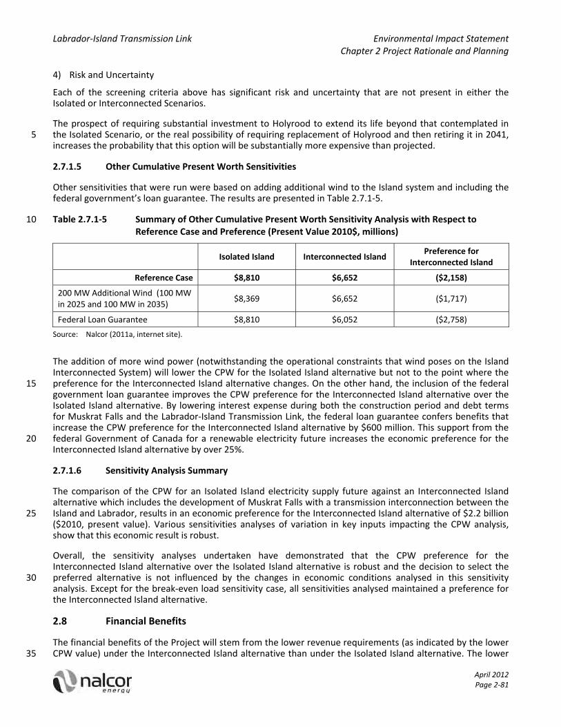
Labrador‐Island Transmission Link Environmental Impact Statement Chapter 2 Project Rationale and Planning
April 2012 Page 2‐81
4) Risk and Uncertainty
Each of the screening criteria above has significant risk and uncertainty that are not present in either the Isolated or Interconnected Scenarios.
The prospect of requiring substantial investment to Holyrood to extend its life beyond that contemplated in the Isolated Scenario, or the real possibility of requiring replacement of Holyrood and then retiring it in 2041, 5 increases the probability that this option will be substantially more expensive than projected.
2.7.1.5 Other Cumulative Present Worth Sensitivities
Other sensitivities that were run were based on adding additional wind to the Island system and including the federal government’s loan guarantee. The results are presented in Table 2.7.1‐5.
Table 2.7.1‐5 Summary of Other Cumulative Present Worth Sensitivity Analysis with Respect to 10 Reference Case and Preference (Present Value 2010$, millions)
Isolated Island Interconnected Island Preference for
Interconnected Island
Reference Case $8,810 $6,652 ($2,158)
200 MW Additional Wind (100 MW in 2025 and 100 MW in 2035)
$8,369 $6,652 ($1,717)
Federal Loan Guarantee $8,810 $6,052 ($2,758)
Source: Nalcor (2011a, internet site).
The addition of more wind power (notwithstanding the operational constraints that wind poses on the Island Interconnected System) will lower the CPW for the Isolated Island alternative but not to the point where the preference for the Interconnected Island alternative changes. On the other hand, the inclusion of the federal 15 government loan guarantee improves the CPW preference for the Interconnected Island alternative over the Isolated Island alternative. By lowering interest expense during both the construction period and debt terms for Muskrat Falls and the Labrador‐Island Transmission Link, the federal loan guarantee confers benefits that increase the CPW preference for the Interconnected Island alternative by $600 million. This support from the federal Government of Canada for a renewable electricity future increases the economic preference for the 20 Interconnected Island alternative by over 25%.
2.7.1.6 Sensitivity Analysis Summary
The comparison of the CPW for an Isolated Island electricity supply future against an Interconnected Island alternative which includes the development of Muskrat Falls with a transmission interconnection between the Island and Labrador, results in an economic preference for the Interconnected Island alternative of $2.2 billion 25 ($2010, present value). Various sensitivities analyses of variation in key inputs impacting the CPW analysis, show that this economic result is robust.
Overall, the sensitivity analyses undertaken have demonstrated that the CPW preference for the Interconnected Island alternative over the Isolated Island alternative is robust and the decision to select the preferred alternative is not influenced by the changes in economic conditions analysed in this sensitivity 30 analysis. Except for the break‐even load sensitivity case, all sensitivities analysed maintained a preference for the Interconnected Island alternative.
2.8 Financial Benefits
The financial benefits of the Project will stem from the lower revenue requirements (as indicated by the lower CPW value) under the Interconnected Island alternative than under the Isolated Island alternative. The lower 35
Labrador‐Island Transmission Link Environmental Impact Statement Chapter 2 Project Rationale and Planning
April 2012 Page 2‐82
revenue requirements means, all things being equal, that wholesale rates (and thus retail rates) will be lower under the Interconnected Island alternative than under the Isolated Island alternative.
2.8.1 Wholesale Rates
To forecast the annual financial costs for utility operations, and for a longer term electricity rate trend analysis, NLH undertakes an analysis of what its financial costs are for each and every year of the analysis period. While 5 the majority of NLH’s costs are related to the Island power grid, it also incurs costs for its customers served from the Labrador power grid and from isolated diesel systems. Regulated costs incurred to serve Labrador grid and diesel system customers have been identified and excluded from this revenue requirement analysis. This annual revenue requirement can be summarized as the sum of the following general cost categories:
operating and maintenance expenses; 10
fossil fuel costs;
purchase power expenses from third or related parties;
annual capital charges, comprised of:
depreciation; and
return on rate base, comprised of: 15
o interest expenses; and
o return on equity.
all other miscellaneous net cost items.
NLH’s total revenue requirement in any given year in the planning period entails building up the costs for existing operating expenses and capital assets, with the incremental operating expenses and capital charges 20 for a future long‐term generation expansion plan. This is accomplished with the Revenue Requirement Model (RRM). The output of the RRM is an annual revenue requirement due from customers where prices are taken to be set such that revenues are perfectly matched to costs.
As applicable, the RRM uses the same corporate data as those used by Strategist® for production costing (e.g., load forecast, fuel prices, capital, cost of capital, escalation) in the determination of customer revenue 25 requirement. This dual input process across two separate modeling environments provides an inherent check on the integrity of the Strategist® results.
To develop the annual revenue requirements the RRM draws together a wide range of financial data such as:
net book value by class for existing assets;
depreciation schedules for existing assets; 30
operating budgets for existing operations;
forecasts for sustaining capital from 5 and 20 year capital plans;
various rate base items such as deferred charges, inventories and exchange losses;
existing debt, cost and term;
cost of new debt; 35
cost of equity; and
budgeted revenues.

Labrador‐Island Transmission Link Environmental Impact Statement Chapter 2 Project Rationale and Planning
April 2012 Page 2‐83
The inputs from Strategist® to RRM will be unique to each alternative generation expansion plan under study and analysis. The general categorization of Strategist® input costs to RRM are:
In‐Service capital costs for a new generation plant, whether required to maintain appropriate generation planning criteria or replacement capital for an obsolete plant;
operating costs associated with all new generation plants; 5
energy production by type (thermal, hydroelectric, wind); and
purchased energy and associated costs.
For regulated utilities, return on rate base includes a profit component for shareholders (return on equity) and a cost component for lenders (cost of debt). The recovery of these costs in customer rates enables the utility to finance assets used in the provision of electrical service. For each new generation plant identified by 10 Strategist®, the RRM will finance the asset, place it into rate base, and set up a depreciation charge applicable for that class of assets. The return on rate base is calculated on total rate base for the company. While the cost of debt and equity capital are used in a consistent manner with Strategist®, the RRM has additional analysis detail on an annual basis for new debt issues (short or long‐term), targeted capital structure, dividend policies and weighted cost of capital. 15
There are key regulated capital parameters that are brought together to enable the calculation for the return on rate base:
Debt‐equity ratio: the capital structure for the company establishes the appropriate levels of debt and equity capitalization. Capital structure is normally approved by the regulator. The target debt ratio for NLH revenue requirement purposes has been set at 75% consistent with its current targets. The target equity 20 ratio has been set at 25%.
Debt: The cost of debt is a function of both the embedded cost of existing debt and the cost of projected new debt. The historical or embedded cost of debt for NLH is approximately 8.8%. Going forward, the cost of debt will take into account new debt. Projections for the cost of new NLH debt are tied to forecasts prepared by the Conference Board of Canada. The forecasted long‐term average cost of new NLH debt is 25 7.3%.
Equity: Going forward, Government directive is that the return on equity for NLH will be set on a consistent basis with Newfoundland Power. The forecast longer term average return on equity for regulated utilities is expected to be in the range of 9% to 10%. The return on equity will be no more, or no less, than a regulated industry standard. 30
WACC: Combining capital structure weighting with its cost by capital component results in a weighted cost of capital of 8%, which is also used consistently in Strategist® and taken as the discount rate for analytical purposes.
The total revenue requirement for any given year is the sum of that year’s operating costs, power purchases, fuel expenses, depreciation and return on rate base. Combining the total annual revenue requirement from 35 customers with total wholesale energy to be delivered as per the 2010 PLF provides a projection of the overall wholesale rate trends for the electricity supply futures under analysis. These trends are illustrated in Table 2.8.1‐1.
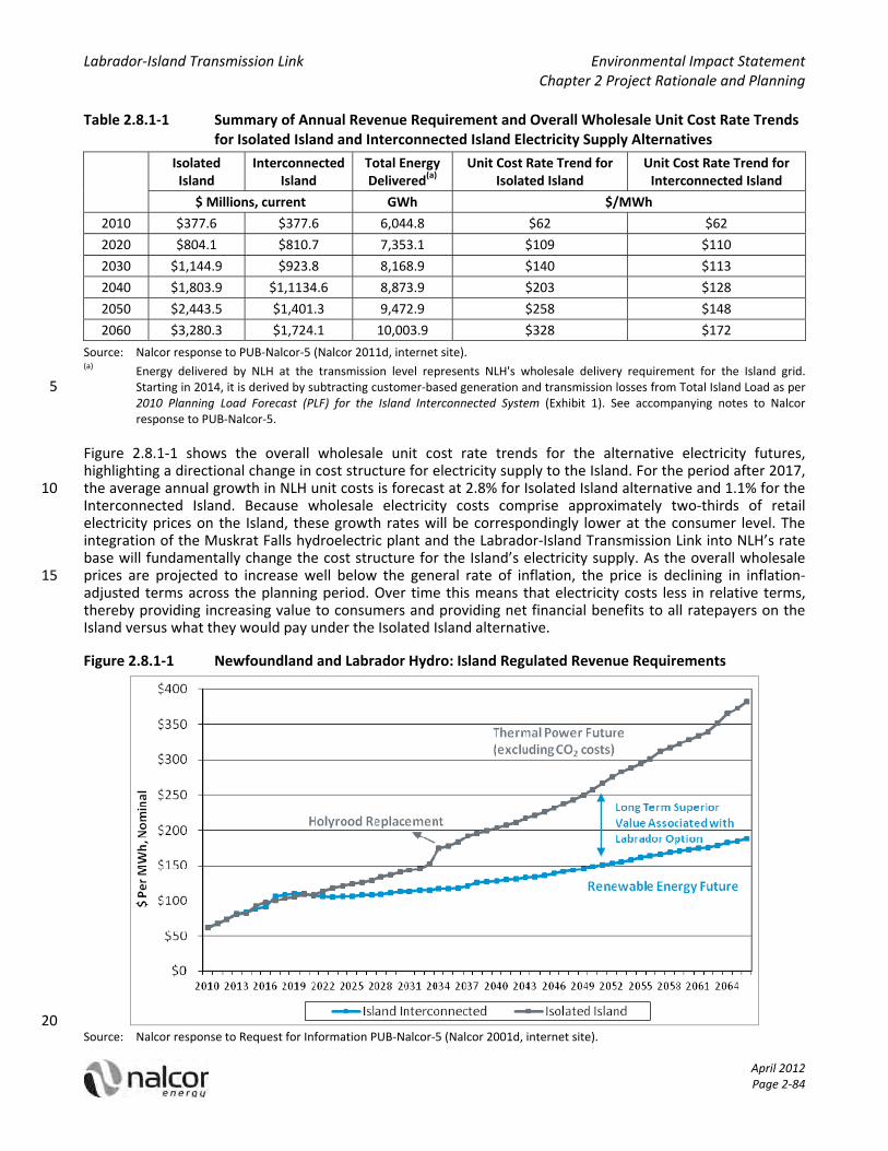
Labrador‐Island Transmission Link Environmental Impact Statement Chapter 2 Project Rationale and Planning
April 2012 Page 2‐84
Table 2.8.1‐1 Summary of Annual Revenue Requirement and Overall Wholesale Unit Cost Rate Trends for Isolated Island and Interconnected Island Electricity Supply Alternatives
Isolated Island
Interconnected Island
Total Energy Delivered(a)
Unit Cost Rate Trend for Isolated Island
Unit Cost Rate Trend for Interconnected Island
$ Millions, current GWh $/MWh
2010 $377.6 $377.6 6,044.8 $62 $62
2020 $804.1 $810.7 7,353.1 $109 $110
2030 $1,144.9 $923.8 8,168.9 $140 $113
2040 $1,803.9 $1,1134.6 8,873.9 $203 $128
2050 $2,443.5 $1,401.3 9,472.9 $258 $148
2060 $3,280.3 $1,724.1 10,003.9 $328 $172
Source: Nalcor response to PUB‐Nalcor‐5 (Nalcor 2011d, internet site). (a) Energy delivered by NLH at the transmission level represents NLH's wholesale delivery requirement for the Island grid.
Starting in 2014, it is derived by subtracting customer‐based generation and transmission losses from Total Island Load as per 5 2010 Planning Load Forecast (PLF) for the Island Interconnected System (Exhibit 1). See accompanying notes to Nalcor response to PUB‐Nalcor‐5.
Figure 2.8.1‐1 shows the overall wholesale unit cost rate trends for the alternative electricity futures, highlighting a directional change in cost structure for electricity supply to the Island. For the period after 2017, the average annual growth in NLH unit costs is forecast at 2.8% for Isolated Island alternative and 1.1% for the 10 Interconnected Island. Because wholesale electricity costs comprise approximately two‐thirds of retail electricity prices on the Island, these growth rates will be correspondingly lower at the consumer level. The integration of the Muskrat Falls hydroelectric plant and the Labrador‐Island Transmission Link into NLH’s rate base will fundamentally change the cost structure for the Island’s electricity supply. As the overall wholesale prices are projected to increase well below the general rate of inflation, the price is declining in inflation‐15 adjusted terms across the planning period. Over time this means that electricity costs less in relative terms, thereby providing increasing value to consumers and providing net financial benefits to all ratepayers on the Island versus what they would pay under the Isolated Island alternative.
Figure 2.8.1‐1 Newfoundland and Labrador Hydro: Island Regulated Revenue Requirements
20 Source: Nalcor response to Request for Information PUB‐Nalcor‐5 (Nalcor 2001d, internet site).

Labrador‐Island Transmission Link Environmental Impact Statement Chapter 2 Project Rationale and Planning
April 2012 Page 2‐85
2.8.2 Retail Rates
NLH has also provided initial estimates for the retail consumer rate effect arising from the alternative generation expansion plans for the Island. Table 2.8.2‐1 provides the impact on the average consumer rate for the Island grid resulting from the transition of wholesale costs through to retail. NLH has not factored in periodic rate increases attributable to the retail distribution utility. In addition, while these rate estimates were 5 prepared at Decision Gate 2 (see Section 2.10) before the subsequent retail tax change announced by the Provincial Government, the cumulative percentage change for retail rates would not change.These projected rate impacts are attributable only to the alternative electricity supply futures as analyzed through the preceding revenue requirement analysis.
Table 2.8.2‐1 Projected Impact on Average Consumer Rate for the Island Grid 10
Isolated Island Alternative ($/MWh) Interconnected Island Alternative ($/MWh)
Overall NLH
Wholesale Rate
Utility Wholesale
Rate
Utility Retail Rate
Cumulative Retail Rate Increase
Overall NLH Wholesale
Rate
Utility Wholesale
Rate
Utility Retail Rate
Cumulative Retail Rate Increase
2011 $68 $64 $112 ‐ $68 $64 $112 ‐
2012 $73 $71 $120 7% $73 $71 $120 7%
2013 $81 $83 $133 19% $81 $83 $133 19%
2014 $83 $85 $136 21% $84 $86 $137 22%
2015 $92 $95 $146 30% $88 $92 $143 27%
2016 $97 $103 $154 37% $91 $96 $147 31%
2017 $100 $106 $158 41% $107 $113 $164 47%
2018 $104 $110 $161 44% $108 $115 $166 48%
2019 $106 $112 $164 46% $110 $118 $169 51%
2020 $109 $116 $168 49% $110 $118 $170 51%
2030 $140 $149 $198 77% $113 $123 $174 55%
2040 $203 $213 $252 125% $128 $138 $189 68%
Source: Nalcor response to PUB‐Nalcor‐5 and accompanying notes (Nalcor 2011d, internet site).
The favourable change in cost structure associated with the Interconnected Island alternative translates directly through to the average retail rate for all domestic customers on the Island grid. Under the Isolated Island alternative, the average domestic rate is projected to be about 37% higher in 2016 than in 2011. As the respective cost structures for the future supply alternatives begin their diverging trends beginning around 15 2020, the value of an Interconnected Island alternative begins to accumulate. By 2040, the cumulative rate increase for Island domestic consumers attributable to the Interconnected Island alternative is projected at 68%, in contrast to a cumulative rate increase of 125% for the Isolated Island.
2.8.3 Summary
The preparation of NLH’s annual revenue requirement includes all operating and annualized capital costs 20 associated with each respective generation planning alternative, and in addition, all common operating and capital related costs from NLH’s existing operations not directly included in the Strategist® analysis. The overall

Labrador‐Island Transmission Link Environmental Impact Statement Chapter 2 Project Rationale and Planning
April 2012 Page 2‐86
wholesale rate for NLH is derived by dividing its annual wholesale cost by its annual wholesale energy deliveries. The trend in NLH wholesale unit costs is largely the same until 2017 regardless of long‐term electricity supply alternative, primarily because of the association with fuel prices and the consumption of fuel at Holyrood. Beyond 2020, the cost trends for Isolated and Interconnected Island generation expansion alternatives begin to diverge, reflecting the change in NLH cost structure under each respective case. Unit cost 5 trends for the Isolated Island alternative increase at an annual rate of change that exceeds the general inflation rate. By contrast, the Interconnected Island wholesale rate trend is stable with an annual percentage change that tracks below the general rate of inflation, thus offering increasing value to consumers over time.
2.9 Environmental Benefits of the Project
Nalcor’s analysis of the Interconnected Island (Project) and Isolated Island (no Project) alternatives did not 10 include a cost for GHG emissions. The emissions associated with the two alternatives are significantly different, based on forecasted fuel requirements for each scenario. The GHG emissions associated with the two alternatives are presented in Table 2.9‐1, while fuel consumption for NLH’s generation for the two alternatives is shown in Table 2.9‐2.
Table 2.9‐1 GHG Emissions for Newfoundland and Labrador Hydro’s Generation Planning 15 Alternatives (’000s tonnes)
Year Interconnected Island Isolated Island
2010 820 820
2011 756 756
2012 791 791
2013 1,078 1,078
2014 1,292 1,273
2015 1,382 1,294
2016 1,395 1,188
2017 2 1,219
2018 2 1,266
2019 2 1,217
2020 2 1,259
2025 1 1,522
2030 4 1,831
2035 5 1,814
2040 8 1,826
2045 10 2,005
2050 13 2,187
2055 22 2,345
2060 38 2,504
2065 59 2,658
Source: NLH System Planning.

Labrador‐Island Transmission Link Environmental Impact Statement Chapter 2 Project Rationale and Planning
April 2012 Page 2‐87
Table 2.9‐2 Fuel Consumption for Newfoundland and Labrador Hydro’s Generation Planning Alternatives (’000s barrels)
Year Isolated Island Interconnected Island
#6 Fuel #2 Fuel #6 Fuel #2 Fuel
2010 1,636 13 1,636 13
2011 1,510 10 1,510 10
2012 1,580 11 1,580 11
2013 2,147 21 2,147 21
2014 2,529 33 2,566 34
2015 2,587 36 2,742 39
2016 2,362 29 2,768 40
2017 2,421 31 3 1
2018 2,512 35 3 1
2019 2,415 33 3 1
2020 2,498 36 3 1
2025 2,997 67 ‐ 3
2030 3,537 158 ‐ 8
2035 1,460 2,452 ‐ 12
2040 ‐ 4,116 ‐ 18
2045 ‐ 4,521 ‐ 23
2050 ‐ 4,930 ‐ 30
2055 ‐ 5,287 ‐ 49
2060 ‐ 5,646 ‐ 86
2065 ‐ 5,992 ‐ 132
Source: NLH System Planning.
2.10 Risks and Risk Management
Given the scope and scale of the Project and its associated capital cost, Nalcor has implemented a 5 comprehensive risk management framework for the Project. Specific project‐level risk management processes, tools and resources have been implemented for the Project underneath the umbrella of Nalcor’s corporate Enterprise Risk Management program.
Consistent with the “Project Influence Curve” shown in Figure 2.10‐1, Nalcor has made extensive efforts in the early planning phases to identify, evaluate and implement opportunities to capture and maximize value that 10 can be extracted from the Project. Nalcor believes that early risk (both opportunity and threats) planning is the key driving factor in increasing the predictability of the underlying business case for the Project, and has taken extensive steps to ensure the application of best practice for risk planning.

Labrador‐Island Transmission Link Environmental Impact Statement Chapter 2 Project Rationale and Planning
April 2012 Page 2‐88
Figure 2.10‐1 Project Influence Curve
Source: Westney Consulting Group Inc. (Westney) (2008).
To this effect, Nalcor engaged Westney Consulting Group Inc. (Westney) to assist with the full implementation of a holistic risk management program with the Project. Westney are well known within the capital project 5 industry for their leading‐edge ideologies and approaches to addressing risks as a means to improve the predictability of the investment decision.
As illustrated in Figure 2.10‐2 Nalcor has adopted Westney’s Risk Resolution® methodology as the backbone of its risk management process for the Project.
Figure 2.10‐2 Nalcor’s Application of Westney’s Risk Resolution Methodology 10
IDENTIFY & FRAMEDEVELOP RESOLUTION
STRATEGIESRESOLVE & MITIGATE
• RISK DISCOVERY
• RISK ASSESSMENT
• RISK DEFINITION
• HOLISTIC COLLABORATION
• STRATEGIC DECISION‐MAKING & PLANNING
• RISK BROKERING
• RISK MONITORING & SURVEILLANCE
• Risk Heat Map
• Risk Frames
• Risk Analysis
• Risk‐Conditioned Investment Value
• Mitigation & Risk Action Plan & LACTI Charts
• Risk‐Driven Strategic Project Plan
• Risk Balance Sheet
• Risk – Resolved Agreements
• Risk Collar
Source: Westney (2008).

Labrador‐Island Transmission Link Environmental Impact Statement Chapter 2 Project Rationale and Planning
April 2012 Page 2‐89
Westney’s Risk Resolution® methodology represents a departure from the conventional approach to project risk management whereby risk analysis is focused on tactical risks. According to Westney, conventional project risk management fails to consider larger “strategic” risks that have had a predominant influence on mega‐projects in recent years. As illustrated in Figure 2.10‐3, these strategic risks have both large level of volatility and exposure. 5
Figure 2.10‐3 Relationships between Risk Exposure and Volatility
Source: Westney (2009).
Tactical risks and strategic risks are differentiated below:
Tactical Risks: 10
Definition Risks – These risks are associated with the degree of design development and planning definition for the given project scope, including such items as rock quantities, changing design criteria, location‐driven factors, etc.
Performance Risks – These risks are associated with normal / reasonably expected variations in owner and contractor performance, including such items as construction productivity risk, weather delays, 15 material pricing, etc.
Strategic Risks:
Background (external) Risks – These are typically associated with changes in scope, market conditions, location factors, commercial or partner requirements and behaviours.
Labrador‐Island Transmission Link Environmental Impact Statement Chapter 2 Project Rationale and Planning
April 2012 Page 2‐90
Organization (internal) Risks – These risks are typically associated with an asymmetry between size, complexity, and difficulty of projects and the organization’s ability to deliver.
2.10.1.1 Risk Management Approach and Methodology
Application of the Risk Resolution® methodology began when the Project was in its earliest, formative stage and before major business decisions or commercial commitments were made. This methodology started with 5 the identification and framing of all business and project risks with a technique called Risk Framing, which provides a means of assessing risk exposure prior to finalizing input parameters into the economic model used for investment evaluation. Through the use of interviews, surveys and analyses, major sources of risk and possible mitigation strategies were identified. Scenarios were created to represent the best‐ and worst‐case outcomes for each type of risk, and then used as input to purpose‐built, Monte‐Carlo simulation models for 10 cost and schedule that provide a range of possible values for Risk Exposure as input into risk‐informed decision making.
Nalcor’s specific risk management programs for the Project are built upon a framework that includes five (5) categories:
Commercial: Including risks to how the capital project will produce revenue via PPAs with suppliers, off‐15 takers, transmission access and tariffs, reservoir production rates, etc.
Financial: Including risks to how the project’s capital investment will be paid for via arrangements with partners, lenders, etc.
Regulatory & Stakeholder: Includes risks regarding regulatory approvals, Aboriginal consultations and agreements, stakeholder engagement, etc. 20
Technical: Including risks of the technology to be used to create the facilities required to produce the expected revenue, and the physical scope of those facilities.
Execution: Including risks to the organization and contracting strategies for performing the engineering, procurement, construction, installation and start‐up, and the plans for managing those activities.
2.10.1.2 Risk Management Philosophy 25
The underlying risk management philosophy adopted by Nalcor has been to package and allocate Project risks to the party who can most effectively manage the risks. The ability of Nalcor to allocate these risks will be very much dependent on the risk appetite of the various stakeholders (e.g., contractors, off‐takers, insurance underwriters, etc.). A Risk Resolution Team was formed in 2007 to determine the optimal resolution strategy for the identified risks. Since then, this multi‐faceted and disciplinary team has successfully developed and 30 implemented mitigation strategies and plans for a number of risks to the Project.
Nalcor has extensively used risk‐informed decision‐making techniques to facilitate decision quality assurance for all aspects of the business case evaluation and Project planning. While Nalcor considers it to be impractical to think that it can identify and manage all risks to which the Project may be exposed, the risk‐informed decision‐making approach facilitates decision analysis that is inclusive of all risk and uncertainty 35 considerations.
2.10.1.3 Gateway Process
Quality assurance for decision making, as a mechanism to improve project predictability, has been incorporated within the planning and execution of the Project by implementing Nalcor’s structured stage‐gate process – the Gateway Process. The Gateway Process divides the lifecycle of the Project into several phases 40 starting at opportunity identification and concluding at start‐up of the production facility. Each Phase has a list of pre‐defined deliverables deemed essential to make a risk‐informed decision at the end of that Phase, referred to as a Gate.

Labrador‐Island Transmission Link Environmental Impact Statement Chapter 2 Project Rationale and Planning
April 2012 Page 2‐91
A due diligence review is required prior to the decision at each Gate. The due diligence review provides an independent review of the status, progress, plans, issues and risks on each Project Plane, then integrates these into the overall assessment of project risk exposure. These results drive risk‐informed decisions and plans on each Project Plane.
As illustrated in Figure 2.10.1‐1, Nalcor has leveraged the Risk Resolution® methodology as a key component of 5 its process to facilitate risk‐informed decision making within the Phases and each Gate of the Gateway Process.
Figure 2.10.1‐1 Risk‐informed Decision Making Approach
Risk Framingand
Analysis
Technical
Regulatory / Stakeholder
Financial
Execution
Risk‐Informed Decisions& De‐Risking Strategies
FinancialRisks
Regulatory &Stakeholder Risks
TechnicalRisks
ExecutionRisks
Risk Exposure‐ Capital‐ Schedule
‐ Financing‐ Production‐ Revenue
CommercialRisks
Commercial
Risk Framingand
Analysis
Technical
Regulatory / Stakeholder
Financial
Execution
Risk‐Informed Decisions& De‐Risking Strategies
FinancialRisks
Regulatory &Stakeholder Risks
TechnicalRisks
ExecutionRisks
Risk Exposure‐ Capital‐ Schedule
‐ Financing‐ Production‐ Revenue
CommercialRisks
Commercial
Source: Nalcor.
2.10.1.4 Project Specific Risks 10
Extensive risk planning exercises by Nalcor have resulted in the identification and development of mitigation strategies for a number of tactical and strategic project risks. Several of these key risks are discussed below.
Schedule Delays
Schedule delays may occur during either the pre‐sanction (Gate 3) period or during the construction execution phase. Nalcor has identified a number of tactical and strategic risks that may result in schedule delays. These 15 include, but are not limited to:
securing PPAs;
securing transmission access agreements;
negotiation of Aboriginal agreements;
achieving release from EA; 20
availability of qualified engineering consultants;
availability and retention of skilled construction labour and supervision;
availability of experienced contractors;
uncertain geotechnical conditions;
winter construction limitations; 25
late design change; and

Labrador‐Island Transmission Link Environmental Impact Statement Chapter 2 Project Rationale and Planning
April 2012 Page 2‐92
site access and logistics.
Consistent with the Risk Resolution® methodology, Risk Frames for these risks have been developed, which thoroughly define the risk and mitigation plans. These Risk Frames include a view of unmitigated and mitigated exposure to each risk, which is used as input to a purpose‐built Monte‐Carlo simulation model for schedule that provide a range of possible values for Risk Exposure as input into risk‐informed decision making. All 5 economic modelling for the Project have considered a range of probabilistic schedule completion dates when assessing the business investment. Westney has leveraged its proprietary PRIMS® modeling technique to facilitate the modeling of schedule risks.
Regulatory Risk
As discussed above, the justification of the Project on energy terms is based partially on the evolution of 10 electricity markets where GHG emissions are restricted. Changes to the regulatory regime therefore represent a risk, as the competitiveness of the Project in the marketplace will change relative to that of other generation alternatives. In particular, a relaxation of proposed GHG emission rules would re‐introduce coal fired generation as a viable alternative. In light of the stated policies of both federal and provincial governments, this is considered to be a low risk at this time. 15
Nalcor continues to actively monitor regulatory policy decisions that may impact the Project so as to effectively ensure the consideration of this risk during Project decision making.
Interest Rates
Prior to Decision Gate 3, the Project will have established and secured equity financing, and remaining financing will be provided via debt markets. To mitigate any risk related to interest rate exposure, the Project 20 intends to finance using conventional fixed rate financing obtained in bond markets and / or bank financing where floating rate exposure is eliminated via the purchase of interest rate swaps, effectively creating a fixed interest rate for the debt secured. Accordingly, interest rate risk is mitigated through use of this financing strategy. Project economics have been prepared using an assumption for a fixed interest rate that is viewed as reasonable by the Project and its financial advisors at the date of completing this report. Another component 25 of the risk management strategy for project financing is the negotiation of a loan guarantee from the federal government.
Construction Cost Risk
Consistent with the approach discussed in this section, Nalcor has gone through an extensive process to identify and assess potential construction cost risk, encompassing the four categories of risks: Definition Risks, 30 Performance Risks, Background (external) Risks, and Organization (internal) Risks. Following a detailed qualitative review of identified risks, key risks were further assessed using quantitative methods including the use of Monte‐Carlo simulation techniques. When combined with the schedule delay analysis, the results included a range of possible outcomes that is used to make informed decisions on pragmatic levels to include for Estimate Contingency and Strategic Risk Exposure that have been included in economic modeling for the 35 Project. Westney has provided Monte‐Carlo simulation modeling tools and techniques to assist in the completion of this analysis.
Consistent with Nalcor’s governance plans for the Project, all capital cost and schedule estimates are prepared consistent with industry recognized best practice so as to ensure that all business planning and investment evaluation activities are completed using information commensurate with the level of technical and execution 40 detail available. Capital cost estimates prepared for the purposes of business planning and investment evaluation will be comprised of three distinct components as illustrated and defined in Figure 2.10.1‐2.
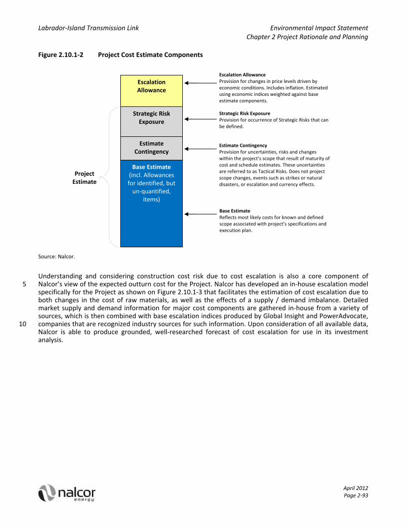
Labrador‐Island Transmission Link Environmental Impact Statement Chapter 2 Project Rationale and Planning
April 2012 Page 2‐93
Figure 2.10.1‐2 Project Cost Estimate Components
Source: Nalcor.
Understanding and considering construction cost risk due to cost escalation is also a core component of Nalcor’s view of the expected outturn cost for the Project. Nalcor has developed an in‐house escalation model 5 specifically for the Project as shown on Figure 2.10.1‐3 that facilitates the estimation of cost escalation due to both changes in the cost of raw materials, as well as the effects of a supply / demand imbalance. Detailed market supply and demand information for major cost components are gathered in‐house from a variety of sources, which is then combined with base escalation indices produced by Global Insight and PowerAdvocate, companies that are recognized industry sources for such information. Upon consideration of all available data, 10 Nalcor is able to produce grounded, well‐researched forecast of cost escalation for use in its investment analysis.
Escalation Allowance
Strategic Risk Exposure
EstimateContingency
Base Estimate(incl. Allowances for identified, but un‐quantified,
items)
Escalation AllowanceProvision for changes in price levels driven by economic conditions. Includes inflation. Estimated using economic indices weighted against base estimate components.
Strategic Risk ExposureProvision for occurrence of Strategic Risks that can be defined.
Estimate ContingencyProvision for uncertainties, risks and changes within the project’s scope that result of maturity of cost and schedule estimates. These uncertainties are referred to as Tactical Risks. Does not project scope changes, events such as strikes or natural disasters, or escalation and currency effects.
Base EstimateReflects most likely costs for known and defined scope associated with project’s specifications and execution plan.
Project Estimate
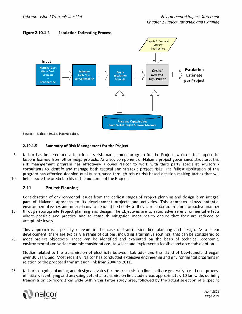
Labrador‐Island Transmission Link Environmental Impact Statement Chapter 2 Project Rationale and Planning
April 2012 Page 2‐94
Figure 2.10.1‐3 Escalation Estimating Process
Nominal Cost(Base Cost Estimate
+Contingency)
EstimateCash Flow
per Commodity
ApplyEscalationFormula
CapitalDemand
Adjustment
Price and Capex IndicesFrom Global Insight & PowerAdvocate
Supply & DemandMarket
Intelligence
Input
EscalationEstimateper Project
Source: Nalcor (2011a, internet site).
2.10.1.5 Summary of Risk Management for the Project
Nalcor has implemented a best‐in‐class risk management program for the Project, which is built upon the 5 lessons learned from other mega‐projects. As a key component of Nalcor’s project governance structure, this risk management program has effectively allowed Nalcor to work with third party specialist advisors / consultants to identify and manage both tactical and strategic project risks. The fullest application of this program has afforded decision quality assurance through robust risk‐based decision making tactics that will help assure the predictability of the outcome of the Project. 10
2.11 Project Planning
Consideration of environmental issues from the earliest stages of Project planning and design is an integral part of Nalcor’s approach to its development projects and activities. This approach allows potential environmental issues and interactions to be identified early so they can be considered in a proactive manner through appropriate Project planning and design. The objectives are to avoid adverse environmental effects 15 where possible and practical and to establish mitigation measures to ensure that they are reduced to acceptable levels.
This approach is especially relevant in the case of transmission line planning and design. As a linear development, there are typically a range of options, including alternative routings, that can be considered to meet project objectives. These can be identified and evaluated on the basis of technical, economic, 20 environmental and socioeconomic considerations, to select and implement a feasible and acceptable option.
Studies related to the transmission of electricity between Labrador and the Island of Newfoundland began over 30 years ago. Most recently, Nalcor has conducted extensive engineering and environmental programs in relation to the proposed transmission link from 2006 to 2011.
Nalcor’s ongoing planning and design activities for the transmission line itself are generally based on a process 25 of initially identifying and analyzing potential transmission line study areas approximately 10 km wide, defining transmission corridors 2 km wide within this larger study area, followed by the actual selection of a specific
Labrador‐Island Transmission Link Environmental Impact Statement Chapter 2 Project Rationale and Planning
April 2012 Page 2‐95
routing a ROW averaging approximately 60 m wide. At each stage, progressively narrower spatial scales and greater detail, based on technical, economic, social and environmental considerations and constraints, are applied. This process is described further below.
Project planning and design are currently at a stage of having identified a proposed 2 km wide corridor for the overland transmission line and a 500 m wide corridor for the proposed Strait of Belle Isle submarine cable 5 crossing. The corridors will be the subject of further detailed engineering analysis, environmental review and Aboriginal, stakeholder and public consultation, and will remain the focus of the Project’s EA and associated consultations. The eventual transmission line itself will, however, once fully designed, occupy only a narrow cleared area within this overall study area. At that time the transmission corridor itself will cease to have any real relevance or meaning. 10
Following further engineering analysis, environmental review and consultation, and pending EA approval, a specific route for the transmission line will eventually be selected from within this larger 2 km wide corridor described above. The transmission line will be constructed along this route within a ROW averaging approximately 60 m in width. This eventual transmission route will be selected with consideration of technical, environmental and socioeconomic factors, including the results of the EA, and will be subject to further 15 consultation and permitting.
2.11.1 Transmission Study Area Selection
As an initial step, Nalcor identified a 10 km wide transmission line study area from the lower Churchill River in Central Labrador to Soldiers Pond on the Island of Newfoundland’s Avalon Peninsula. This exercise was based initially on a transmission proposal first made in the late 1970s, and involved considerable further analysis 20 considering relevant changes in technology, the natural and human landscapes and additional information available since that time, including the extensive engineering and environmental work undertaken by Nalcor since 2006.
Study area selection was completed using 1:50,000 scale mapping and digital topographic data, and was undertaken with a view to reducing the line length, while at the same time identifying and avoiding key known 25 technical, environmental and socio‐cultural issues and constraints such as difficult topography and meteorological conditions, protected and other known environmentally sensitive areas.
For the Labrador component of the on‐land transmission line, study area selection was undertaken to identify a pathway within Labrador that would minimize the overall length of the transmission line, and which would take advantage of the Trans‐Labrador Highway (TLH) to provide construction and maintenance access, while at 30 the same time avoiding unfavourable topography such as large waterbodies, hills and wetlands.
For the Island component, physical environment conditions and constraints were key technical considerations on the Northern Peninsula. HVdc transmission lines are sensitive to salt spray from the maritime environment, so it is necessary to locate the line further inland from the coast than much of the existing highway and transmission lines along the western side of the peninsula. It was also necessary to avoid, as possible, the 35 mountainous terrain at the centre of the peninsula. From the southern end of the Northern Peninsula, an attempt was made to minimize the length of the transmission line across north‐central and eastern Newfoundland, while also attempting to take advantage of existing access routes and to avoid unfavourable terrain and existing protected areas. Southeast of Terra Nova National Park, the study area was selected to follow existing transmission lines and roadways to and across the Avalon Peninsula. 40
In the marine environment, several options for the Strait of Belle Isle submarine cable crossings have been considered over the years, including a range of possible landing sites as well as various potential cable routings between them. In the period 2007‐2011 Nalcor has undertaken comprehensive survey programs in the Strait of Belle Isle, the objectives of which have been to identify suitable cable crossing corridors and landing points in the Strait. Information on geology, bathymetry, oceanography, ecology, fisheries, archaeology and other 45 factors were gathered and used as inputs to the survey programs, which has involved detailed side scan and multibeam sonar surveys and sub‐bottom profiles, underwater video surveys, drilling programs and other

Labrador‐Island Transmission Link Environmental Impact Statement Chapter 2 Project Rationale and Planning
April 2012 Page 2‐96
studies to better understand the geological and marine environments in the region. This eventually led to the identification and evaluation of a number of potential cable landings sites on both sides of the Strait, as well as several marine crossing approaches and corridor options, as described below.
2.11.2 Transmission Corridor Selection
Following the selection and detailed analysis of the on‐land transmission line study area described above, a 5 preferred 2 km wide transmission corridor was identified, along with various alternative corridor segments for particular areas.
Similar to the evaluation and selection of a transmission study area, corridor selection was completed with consideration of a number of factors, but at a finer spatial scale. These included attempting to:
minimize the length of the transmission line to the degree possible and practical; 10
avoid unfavourable meteorological conditions (such as heavy icing and / or strong winds);
avoid difficult terrain where possible;
minimize the requirement for new access roads and trails;
minimize watercourse and wetland crossings;
avoid interactions with communities, protected areas and other known environmentally and socially 15 important areas where possible and practical; and
avoid areas of known archaeological and historical importance.
At the time of commencement of the EA, the Labrador component of the Project included a proposed converter station facility at Gull Island on the lower Churchill River, as well as a proposed transmission corridor extending from Gull Island to the Strait of Belle Isle. In mid‐November 2010, Nalcor advised the provincial and 20 federal governments that it would also be assessing the potential option of locating the Project’s Labrador converter station at or near the Muskrat Falls site on the lower Churchill River, as well as an associated transmission corridor that would extend from Muskrat Falls to the Trans‐Labrador Highway Phase 3 (TLH3), and then follow generally along the south side of the highway to approximately its southernmost point before meeting and continuing along the previously identified corridor from that location to the Strait of Belle Isle. 25
This Muskrat Falls to the Strait of Belle Isle transmission corridor has since become the preferred and proposed option for the Project, and is thus the main focus of the EA described in this report. The currently proposed transmission corridor on the Island that is the subject of the EIS generally reflects that which was presented when the EA process was initiated in 2009 (see below).
With regard to the proposed Strait of Belle Isle submarine cable crossings, the information gathered through 30 the above referenced studies led to the initial identification of two potential 500 m wide subsea corridors in which to place the cables under the seabed and across the Strait. These were selected primarily because they would provide natural protection for the cables, giving access to deep water and making use of natural seabed features to shelter the cables in deep valleys and trenches to minimize the possibility of iceberg contact or interaction with fishing activity. Based on these identified corridors, several alternative landing sites were 35 initially identified and considered on the Labrador side, including Forteau Point (the currently preferred option) and L’Anse Amour, whereas on the Newfoundland side, the originally identified potential cable landing sites were at Mistaken Cove and Yankee Point.
Since that time, Nalcor has continued with its project planning and engineering work, and in doing so, has proceeded to evaluate other possible design options and alternatives for the proposed Strait of Belle Isle 40 submarine cable crossing. This is common with any major development project, and included additional engineering and field investigations in 2010 and 2011, which have resulted in an evolution of the proposed design concept for the Strait of Belle Isle cable crossing.
Labrador‐Island Transmission Link Environmental Impact Statement Chapter 2 Project Rationale and Planning
April 2012 Page 2‐97
Nalcor is continuing to focus on Forteau Point as the proposed Labrador cable landing site, given its location and topography and site conditions. Although nearby L’Anse Amour site option was initially identified as an option as well, Nalcor has opted to not move forward with this location due to several factors, including the concerns of local residents that Project activity at this site may have an adverse effect on tourism infrastructure and activity at this location. 5
On the Newfoundland side of the Strait of Belle Isle, ongoing engineering work has also identified Shoal Cove as a site for the cable landing. This location has since become Nalcor’s preferred location, as it provides quicker and easier access to deep water through the on‐land horizontal directional drill (HDD) technology that is planned to be used to install the cables from these locations. This, in turn, has substantial benefits in terms of Project design and overall reliability. 10
The Strait of Belle Isle component of the Project is therefore based on the proposed installation of cables between Forteau Point (Labrador) and Shoal Cove (Newfoundland), as described in detail in Chapter 3 of this EIS. The three cables are planned to be installed from these on‐land locations using HDD technology, out to and under the Strait for up to several kilometres. From there the HDD drill holes will pierce the seabed and the cables will be placed on the seabed within a single marine corridor (rather than two) across the Strait. This 15 single marine corridor is essentially an amalgamation of the two marine cable corridors initially identified and described above, utilizing portions of each corridor along with a new, short segment into the Shoal Cove area.
Further information on the nature and outcomes of Nalcor’s identification and evaluation of proposed and / or alternative concepts and locations for various other aspects and components of the Project (including, for example, the proposed converter stations, electrodes, etc.) is provided in the following sections. 20
2.12 Alternatives Means of Carrying Out the Project
As an important and valuable planning tool, EA is intended to help inform and influence project design, and in doing so, to help address the potential environmental outcomes of proposed development projects. The EA process therefore allows for the identification, analysis and evaluation of potential alternative project concepts and approaches, to help directly incorporate environmental considerations into project planning at an early 25 stage.
As such, and as required under provincial and federal EA legislation and the associated EIS Guidelines and Scoping Document (Government of Newfoundland and Labrador and Government of Canada 2011), the EIS therefore also considers possible alternative means of carrying out the project that are technically and economically feasible, and the potential environmental effects of any such alternative means. 30
As indicated earlier, and as described in further detail in Chapter 3, the proposed Project includes the following key components:
an ac‐dc converter station at Muskrat Falls near the lower Churchill River in Central Labrador;
an overhead transmission line from Muskrat Falls to the Strait of Belle Isle (approximately 400 km);
marine cable crossings of the Strait of Belle Isle with associated infrastructure; 35
an overhead transmission line from the Strait of Belle Isle to Soldiers Pond on the Island’s Avalon Peninsula (approximately 700 km);
a dc‐ac converter station at Soldiers Pond, with some associated Island system upgrades; and
electrodes, or high capacity grounding systems, in the Strait of Belle Isle (Labrador) and Conception Bay (Newfoundland), connected to their respective converter stations by small overhead transmission lines. 40
The Project, particularly during its construction phase, will also include various additional components and works, including access trails, camps, marshalling and lay‐down areas, quarries and borrow pits, and other temporary infrastructure and associated activities.
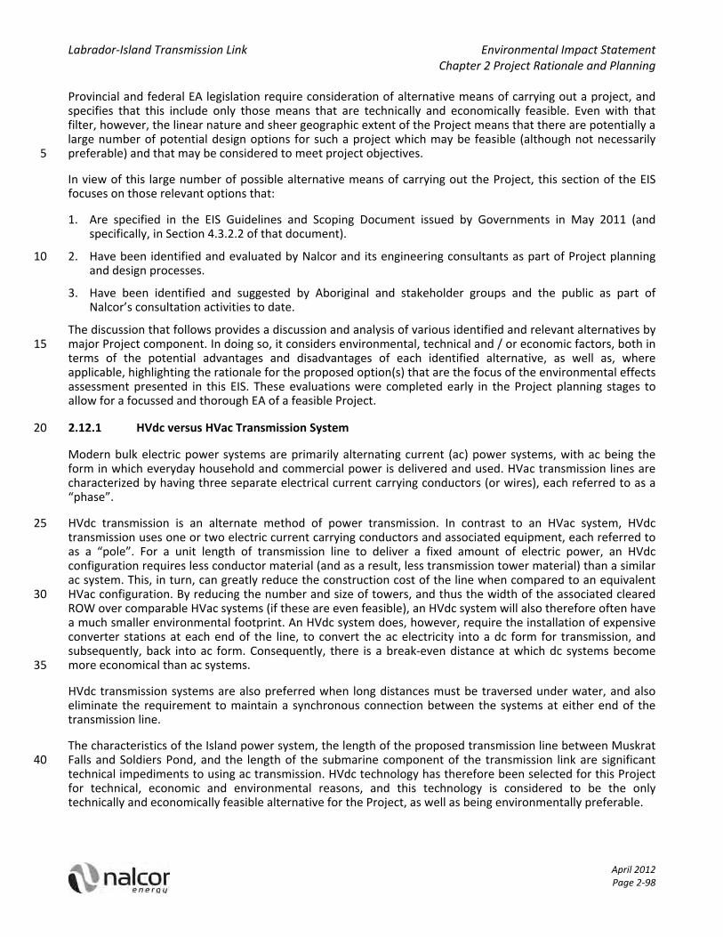
Labrador‐Island Transmission Link Environmental Impact Statement Chapter 2 Project Rationale and Planning
April 2012 Page 2‐98
Provincial and federal EA legislation require consideration of alternative means of carrying out a project, and specifies that this include only those means that are technically and economically feasible. Even with that filter, however, the linear nature and sheer geographic extent of the Project means that there are potentially a large number of potential design options for such a project which may be feasible (although not necessarily preferable) and that may be considered to meet project objectives. 5
In view of this large number of possible alternative means of carrying out the Project, this section of the EIS focuses on those relevant options that:
1. Are specified in the EIS Guidelines and Scoping Document issued by Governments in May 2011 (and specifically, in Section 4.3.2.2 of that document).
2. Have been identified and evaluated by Nalcor and its engineering consultants as part of Project planning 10 and design processes.
3. Have been identified and suggested by Aboriginal and stakeholder groups and the public as part of Nalcor’s consultation activities to date.
The discussion that follows provides a discussion and analysis of various identified and relevant alternatives by major Project component. In doing so, it considers environmental, technical and / or economic factors, both in 15 terms of the potential advantages and disadvantages of each identified alternative, as well as, where applicable, highlighting the rationale for the proposed option(s) that are the focus of the environmental effects assessment presented in this EIS. These evaluations were completed early in the Project planning stages to allow for a focussed and thorough EA of a feasible Project.
2.12.1 HVdc versus HVac Transmission System 20
Modern bulk electric power systems are primarily alternating current (ac) power systems, with ac being the form in which everyday household and commercial power is delivered and used. HVac transmission lines are characterized by having three separate electrical current carrying conductors (or wires), each referred to as a “phase”.
HVdc transmission is an alternate method of power transmission. In contrast to an HVac system, HVdc 25 transmission uses one or two electric current carrying conductors and associated equipment, each referred to as a “pole”. For a unit length of transmission line to deliver a fixed amount of electric power, an HVdc configuration requires less conductor material (and as a result, less transmission tower material) than a similar ac system. This, in turn, can greatly reduce the construction cost of the line when compared to an equivalent HVac configuration. By reducing the number and size of towers, and thus the width of the associated cleared 30 ROW over comparable HVac systems (if these are even feasible), an HVdc system will also therefore often have a much smaller environmental footprint. An HVdc system does, however, require the installation of expensive converter stations at each end of the line, to convert the ac electricity into a dc form for transmission, and subsequently, back into ac form. Consequently, there is a break‐even distance at which dc systems become more economical than ac systems. 35
HVdc transmission systems are also preferred when long distances must be traversed under water, and also eliminate the requirement to maintain a synchronous connection between the systems at either end of the transmission line.
The characteristics of the Island power system, the length of the proposed transmission line between Muskrat Falls and Soldiers Pond, and the length of the submarine component of the transmission link are significant 40 technical impediments to using ac transmission. HVdc technology has therefore been selected for this Project for technical, economic and environmental reasons, and this technology is considered to be the only technically and economically feasible alternative for the Project, as well as being environmentally preferable.

Labrador‐Island Transmission Link Environmental Impact Statement Chapter 2 Project Rationale and Planning
April 2012 Page 2‐99
2.12.2 Converter Stations and Their Locations
At each end of the proposed HVdc system, the Project includes converter station facilities to convert the power from ac to dc (at Muskrat Falls, Labrador) and then from dc back to ac (at Soldiers Pond, Newfoundland).
The Labrador converter station is proposed to be located on the south side of the Churchill River at Muskrat 5 Falls, adjacent to the switchyard for the Lower Churchill Hydroelectric Generation Project, from which the electricity to be transmitted by the Project will be supplied. Although earlier Project concepts saw the Labrador converter station at Gull Island, Nalcor also explored the option of locating the converter station at the Muskrat Falls site. This has become the preferred option for the Project, as the converter station needs to be located as close as possible to the generating facility, and because there is currently no technical or economic 10 benefit of having the converter facility at any other location. Moreover, no other location has been identified that would have different types or degrees of environmental issues and likely effects associated with it, nor have any alternatives been suggested through the EA and associated consultation processes.
A converter station is also required at or near the termination of the HVdc system on the Island to convert the dc electricity transmitted across the line back into ac form. The proposed transmission link extends to the 15 Avalon Peninsula of the Island because this is the region where much of the province’s population resides, and thus, the location of the province's highest electrical demand.
The Newfoundland converter station is proposed to be located at Soldiers Pond, the convergence point of several existing high voltage transmission lines on the Avalon Peninsula. It therefore represents an ideal location at which to inject the electricity transmitted by the Project into the Island grid. For this reason, 20 Soldiers Pond has been the preferred and proposed site for the dc‐ac converter station throughout all of the previous development scenarios and attempts over the past decades. Again, there is no identified technical, economic or environmental rationale or benefit of having the converter facility at any other location.
2.12.3 Strait of Belle Isle Cables: Crossing Approaches
As part of its ongoing planning and design work for the Project, Nalcor assessed two potential concepts for 25 crossing the Strait of Belle Isle:
1. Seabed Crossing: Drilling out to and under the Strait for certain distances, and from there placing cables on the seafloor and protecting them with rock berms, with details as follows:
three (two plus one spare) Mass Impregnated cables;
specific cable routes within the identified marine corridor selected to avoid iceberg scour on the 30 seabed and minimize potential for interaction with external influences and activities;
dedicated HDD holes from each landing site for up to several kilometres (out to nominally 70 m water depth) for each cable (6 HDD holes, approximately 12 km in total); and
each cable protected by a dedicated rock berm (30 km long) between the seafloor exit locations, with approximately 1 million tonnes of rock in total. 35
2. Cable Tunnel Crossing: Placing cables in an approximately 4 to 5 m diameter tunnel under the Strait of Belle Isle.
three (two plus one spare) Mass Impregnated cables;
an approximately 21 km long tunnel (including 17 to 18 km subsea), tunnel depth at approximately 200 m below sea level; 40
approximately 5 to 6 m outside diameter using a tunnel boring machine; and

Labrador‐Island Transmission Link Environmental Impact Statement Chapter 2 Project Rationale and Planning
April 2012 Page 2‐100
tunnel fully lined (necessary for water ingress management and long‐term tunnel stability) with a 4 to 5 m inside diameter.
Over the past number of years, Nalcor has completed detailed analysis and evaluation on both of these potential alternatives. This has included extensive on‐land investigations and marine surveys, detailed technical and economic assessments, risk analyses, and the engagement and advice of national and 5 international experts in these techniques and recent experience with them.
Based on extensive analysis and evaluation, and serious consideration of both options, Nalcor has decided to proceed with the seabed crossing approach for the Project. Various factors were considered in making this determination, including because it represents the option that is:
1. Technically preferred: The seabed option uses a proven approach and techniques. HDD technology is well 10 known and has advanced significantly in recent years. Considerable Eastern Canada and global marine installation experience and expertise exist with regard to rock placement and cable laying. Drilling and seismic investigations have identified major faults, rock formations with various degrees of permeability, and areas of geological uncertainty, which present significant challenges and risks for cost, schedule and safety. 15
2. Financially preferred: The estimated total capital cost of the seabed option is less, as compared to a cable tunnel. There is a high degree of confidence in cost and schedule for the seabed crossing option, whereas the experience with subsea tunnels and tunnels in general is that geological faults and other conditions and unknowns often result in significant cost overruns.
3. Safer to construct and operate: The HDD drilling and marine installation activities associated with the 20 seabed option use standard construction techniques that are regularly employed globally with well‐known safety considerations. In contrast, there are significant concerns about water ingress and other issues during tunnel construction, which pose unacceptable safety issues and risks.
The Cable Tunnel Crossing alternative is therefore not considered to be a technically and economically feasible alternative for the Strait of Belle Isle submarine cable crossing component of the Project. 25
2.12.4 Strait of Belle Isle Cables: Potential Landing Sites and Cable Corridor(s)
In moving forward with the Seabed Crossing approach for the Strait of Belle Isle submarine cables, Nalcor has identified and evaluated a number of potential cable landing sites and associated submarine cable corridors across the Strait over the years. These include possible sites at L’Anse au Clair, Forteau Bay, Forteau Point, L’Anse Amour and others on the Labrador side, and at Yankee Point, Winter Cove, Mistaken Cove, Sandy Cove, 30 Shoal Cove and others on the Island side, as well as various others, and potential cable routings between them. Indeed, the original (2009) Project concept for the proposed Strait of Belle Isle cables saw the preliminary identification of potential cable landing sites at Forteau Point, Labrador and Mistaken Cove, Newfoundland (with alternatives at L'Anse Amour and Yankee Point in Labrador and on the Island, respectively). From there, multiple cables would have been placed in two marine corridors across the Strait. 35
Nalcor has since refined the Project concept to focus on a single proposed marine corridor between Forteau Point (Labrador) and Shoal Cove (Newfoundland). The rationale for the selection of this option is as follows:
The location of Forteau Point on the southern Labrador coast helps to minimize the required crossing distance of the Strait, while also providing good site conditions and topography for the HDD process.
The selection of Forteau Point is also in keeping with the stated preference of stakeholders, so as to avoid 40 important potential socio‐cultural issues and interactions with residents and tourism activity at L'Anse Amour.
Due to its adjacent bathymetry, drilling from the Shoal Cove site provides the best and quickest access to the deeper water, so as to reduce the risk of interactions between the cables and icebergs.

Labrador‐Island Transmission Link Environmental Impact Statement Chapter 2 Project Rationale and Planning
April 2012 Page 2‐101
The proposed placement of the three cables within a single (rather that multiple) cable corridor helps to reduce the overall extent and footprint of the Project in the marine environment, and therefore, its potential effects on its biophysical and socioeconomic components (marine fish and fish habitat, fishing activity, etc.).
The planned use of an HDD approach from on‐land and out to and under the seabed for up to several 5 kilometres on each side of the Strait is also environmentally preferred over other options, such as trenching, as it helps to avoid activity and associated disturbances on the seabed and in and near the water column.
Notwithstanding the environmental benefits associated with the proposed cable landing sites and corridor option, a key rationale for their selection has been to optimize system reliability. Given the key role that the 10 power transmitted through this Project will play in meeting the energy needs to the Island and other jurisdictions, it is imperative that it be designed, constructed and operated at a very high level of reliability. The design option that is feasible and which maximizes this reliability is therefore desired and must be pursued – and so Nalcor will be continuing with its detailed engineering investigations and design on the basis of this option alone. 15
No other cable landing sites or corridors have been identified that would have different types or degrees of environmental issues and likely effects associated with them, nor have any other alternatives been suggested through the EA’s associated consultation processes.
2.12.5 Electrodes
In an HVdc transmission system, the combination of an ac‐dc converter, dc transmission line, and dc‐ac 20 converter is known as a “pole”. This Project has been designed as a bipole system, comprised of two transmission paths and two converters of opposite polarity at each end of the circuit. In order for the HVdc system to operate, a return path permitting the flow of current is required at all times. During normal operation, the two conductors between the two converters provide these paths, and if both poles are in service, the system can operate at capacity. 25
Electrodes, or high capacity grounding systems, are required to be installed at each end of the HVdc transmission system and connected to their respective converter stations. Although there is no direct physical connection between them, the electrodes utilize the earth (or ocean) as a return path in the event that one of the conductors becomes temporarily unavailable.
The Project includes the proposed installation of electrodes in Labrador and on the Island. During normal 30 Project operations, small amounts of electrical current will flow through the electrode (<1 % of system capacity), as the electrode lines carry small unbalanced currents between the poles more or less continuously. In certain circumstances, the HVdc system can operate in a mono‐pole mode during a normal fault (such as when one pole is out of service for maintenance, for up to 100% of design current). Total use of the electrode expected during normal faulting is 10 to 20 hours per year. 35
Extended electrode use would occur, however, during a significant system failure event, such as if two submarine cables were out of service, or if one overhead line conductor cannot be used. Project design is seeking to minimize the potential for and duration of any such events. The purpose, nature and likely use of the Project’s electrodes are described in further detail in Chapter 3 of this EIS.
To provide an acceptable return path, an important design consideration for the installation of such electrodes 40 is ensuring that they are adequately grounded. The electrodes must be established such that conductivity is not obstructed by insulating material, and in general, rock and soil are relatively poor conductors of electricity. Obtaining effective connections therefore often requires the electrodes to be installed in water with suitable salinity. Given the geology of the proposed installation sites at Muskrat Falls and Soldiers Pond, the Project design includes the installation and use of electrodes in the marine environment. 45

Labrador‐Island Transmission Link Environmental Impact Statement Chapter 2 Project Rationale and Planning
April 2012 Page 2‐102
Nalcor originally contemplated the use of sea electrodes installed in Lake Melville in Labrador as well as in Holyrood Bay, Newfoundland, and this concept was reflected in the 2009 EA Registration and Project Description document submitted to initiate the EA process. Further technical review has identified potential issues with these locations, however, including concerns regarding the required salinity levels for the electrode to function properly. Moreover, concerns were also raised by stakeholders during Nalcor’s EA consultation 5 activities regarding the potential presence of a wood‐pole line to Lake Melville and the presence of a sea electrode at this location, including with regard to environmental, visual and access issues. As a result, Nalcor has subsequently revised its Project planning, and no longer proposes to place sea electrodes in Lake Melville or Holyrood Bay.
The current Project concept would see the use of "shore electrodes" at locations on the Labrador side of the 10 Strait of Belle Isle and Conception Bay where the electrode elements will be placed within a wharf or breakwater‐like structure installed adjacent to the shoreline. These locations were identified and selected through an extensive planning and analysis exercise that included consideration of a range of technical, economic and environmental factors and considerations, including: proximity to the proposed converter station site; existing site access and suitability, including any previous development at the site; local 15 infrastructure presence and requirements; detailed electric field simulations using information on required electrode duty, safe voltage gradients, local soils and geology, and anticipated resistivities.
As a result of these analyses, the selected locations for the Project’s electrode components are as follows:
1. Labrador electrode: L’Anse au Diable (Strait of Belle Isle); and
2. Newfoundland electrode: Dowden’s Point (Conception Bay). 20
A wood‐pole transmission line connecting the Labrador converter station to the Strait of Belle Isle electrode will follow the same route / ROW as the HVdc transmission line itself from the lower Churchill River to the submarine cable landing site at the Strait. From there it will generally follow the existing Labrador Straits highway and / or power lines north‐east to the electrode site. Similarly, a wood‐pole line from the Soldiers Pond converter station to the Conception Bay shore electrode will generally follow along existing transmission 25 lines and / or roadways in that region. Nalcor is also studying the feasibility of installing the electrode line on the same structures as the HVdc transmission line between Muskrat Falls and the submarine cable landing site. A final decision will be made during detailed design.
These proposed electrode locations and layouts are currently being brought into the detailed engineering analysis and design phase of the Project, as they have been identified as being technically and economically 30 feasible, and because they meet the Project design requirements and objectives. It is not feasible to carry multiple such options into the detailed engineering and design phase, and given that no site‐specific environmental concerns have been identified through the EA and associated consultations to date, there is no identified environmental rationale for further changing the current planning and design of this aspect of the Project. 35
2.12.6 Overland Transmission Corridor
Project planning and design have identified a proposed 2 km wide corridor for the overland transmission line, extending from Muskrat Falls in Labrador to Soldiers Pond on the Island.
As a linear development, there is potentially an infinite number of alternative transmission corridor routes which may be considered, some of which may, to varying degrees, be considered technically and / or 40 economically feasible, although, not necessarily preferable or environmentally better. The above sections have generally described the process through which the currently proposed transmission corridor was selected, including the proactive consideration of environmental factors.
Labrador‐Island Transmission Link Environmental Impact Statement Chapter 2 Project Rationale and Planning
April 2012 Page 2‐103
In view of this large number of possible transmission corridor options, the following focuses on those relevant options that:
1. are specified in the EIS Guidelines and Scoping Document issued by Governments in May 2011;
2. have been identified and evaluated by Nalcor and its engineering consultants as part of the Project planning and design process; and / or 5
3. have been identified and suggested by Aboriginal and stakeholder groups and the public as part of Nalcor’s consultation activities to date.
The EIS Guidelines and Scoping Document (Government of Newfoundland and Labrador and Government of Canada 2011) make specific reference to the consideration of the following transmission corridor options:
1. Following the Trans‐Labrador Highway Phase 2 (TLH2) and TLH3 along its entirety across southern 10 Labrador to the Strait of Belle Isle.
This option would add approximately 150 km of additional length to the proposed transmission line, which would increase construction costs in the order of $100 million or more, as well as increasing the length of transmission line required for maintenance. It is therefore not considered to be an economically feasible alternative for the Project. 15
2. Following a portion of the TLH3, in combination with new corridor(s) across southern Labrador to the Strait of Belle Isle.
This option reflects the currently proposed Project that is the subject of this EA.
3. Alternative corridors across the Long Range Mountains, including to the Cat Arm Hydroelectric Project and then following the existing Cat Arm Hydroelectric Project transmission corridor south. 20
A Cat Arm corridor option is not possible for several reasons.
The ice loads on the east side of the Northern Peninsula are known to be even higher than those on the west side. From 1977 to 1987, NLH carried out a Climatological Monitoring Program in the region, including installation of a test tower on the eastern side of the Long Range Mountains in the late 1970s. That tower saw significant accumulation of glaze ice and suffered severe damage in its first year, which 25 was repeated in year 2, leading to an immediate technical recommendation that this not be considered a technically feasible option for the Project.
Constructing the line down from the highlands on the east side of the Northern Peninsula would be difficult, and would necessitate crossing the floodplains of the Main River where the line would be much more visible. 30
The presence of the existing transmission lines from Cat Arm through the narrow valley coming south in that area constrains the ability to construct another large transmission line through that area.
As a result, this is not considered to be an economically or technically feasible alternative.
Other identified transmission corridor options on the Northern Peninsula of the Island are described below. 35
The alternative on‐land transmission corridor segments that have been identified and which are subject to further environmental analyses in this EIS are listed and described in Table 2.12.6‐1 and illustrated in Figure 2.12.6‐1, Figure 2.12.6‐2 and Figure 2.12.6‐3.

Labrador‐Island Transmission Link Environmental Impact Statement Chapter 2 Project Rationale and Planning
April 2012 Page 2‐104
Table 2.12.6‐1 Identified Alternative Transmission Line Corridor Segments
Project Alternative (# / Name) Description
A1: Gull Island to Strait of Belle Isle Originally identified transmission corridor in Labrador. No longer under consideration.
A2: North‐west of Strait of Belle Isle
Alternative Segment
Alternate transmission corridor segment near the end of Labrador portion of the transmission corridor, just east of the Quebec border and north of the Strait of Belle Isle.
A3: Point Amour
Alternative Segment
Alternate transmission corridor segment to possible Point Amour cable landing site on Labrador side of the Strait of Belle Isle.
A4: Strait of Belle Isle Newfoundland Side
Alternative Segment
Alternate transmission corridor segment near the beginning of the Island portion of the transmission corridor, near the Strait of Belle Isle.
A5: Great Northern Peninsula (GNP) North‐east
Alternative Segment
Alternate transmission corridor segment to the east of the proposed corridor on the northeastern side of the Northern Peninsula.
A6: GNP West‐central
Alternative Segment
Alternate transmission corridor segment to the west of the proposed corridor near the centre of the Northern Peninsula.
A7: GNP Eastern Long Range Mountain Crossing
Alternative Segment
Alternate transmission corridor segment to the east of the proposed corridor where the corridor crosses the Long Range Mountains.
A7: GNP Eastern Long Range Mountain Crossing
Alternative Segment + A8: GNP International Appalachian Trail Newfoundland and Labrador Alternative Segment
Another alternate transmission corridor segment in the Long Range Mountains area. Suggested by International Appalachian Trail ‐ NL. Makes use of most of A7 (above) and deviates further east for a section.
A9: Birchy Lake Alternative Segment Short alternate transmission corridor segment in the Birchy / Sandy Lakes area of west‐central Newfoundland.
A10: Newfoundland and Labrador Outfitters Association Alternative Segment
Alternate transmission corridor segment in west‐central Newfoundland. Suggested by the NL Outfitters Association.
A11: Avalon Alternative Segment Short alternate transmission corridor segment in the east‐central portion of the Avalon Peninsula

St r ai t
o f Be l le
I sl e
Trans Labrador Highway (Phas
e 3)
Red Bay
Forteau St. Anthony
Mary's Harbour
North West River
Port Hope Simpson
Happy Valley-Goose Bay
L'Anse au Diable
0 20 40
Kilometres
FIGURE 2.12.6-1
Alternative Transmission Corridor Segments - Central and Southeastern Labrador
±
G u l f
o f
S t . L a w r e n c e
A t l a n t i c
O c e a n
L A B R A D O R
Q U E B E C
"S Converter Station
Proposed Transmission Corridor
" Shoreline Electrode
A2: North-west of Strait of Belle Isle
A3: Point Amour
Existing Roads
Muskrat Falls
0913341043-PD-022-GIS

L'Anse au Diable
Shoal Cove!
St. AnthonyForteau
Baie Verte
Flower's Cove
L'Anse-au-Loup
L'Anse-au-Clair
0 20 40
Kilometres
FIGURE 2.12.6-2
Alternative Transmission Corridor Segments - Northern Peninsula
±
A4: Strait of Belle Isle Newfoundland Side
A5: Great Northern Peninsula North-east
A6: Great Northern Peninsula West-central
A7: Great Northern Peninsula EasternLong Range Mountain Crossing
A8: Great Northern Peninsula InternationalAppalachian Trail Newfoundland and Labrador
Proposed Transmission Corridor
Existing Roads
N E W F O U N D L A N D
0913341043-PD-023A-GIS
G u l f
o f
S t . L a w r e n c e

St. John's
Clarenville
Dowden'sPoint
Gander
Grand Falls-Windsor
0 25 50
Kilometres
FIGURE 2.12.6-3
Alternative Transmission Corridor Segments - Central and Eastern Newfoundland and Avalon Peninsula
±A t l a n t i c
O c e a n
N E W F O U N D L A N D
"S Converter Station
Proposed Transmission Corridor
" Shoreline Electrode
A9: Birchy Lake
A10: Newfoundland and LabradorOutfitters Association
A11: Avalon
Existing Roads
SoldiersPond
0913341043-PD-023B-GIS

Labrador‐Island Transmission Link Environmental Impact Statement Chapter 2 Project Rationale and Planning
April 2012 Page 2‐108
In Chapters 11‐14 and 16 of this EIS, the initial and detailed environmental effects assessment is focussed first on the proposed (preferred) Project design concept (as described in detail in Chapter 3). From there, the various alternative transmission corridor segments listed in Table 2.12‐6‐1 are then assessed through a comparison to the predicted environmental effects of the proposed transmission corridor that is the subject of the preceding detailed environmental effects assessment. In doing so, this analysis considers and describes 5 whether and how the potential environmental effects of each alternative segment would likely be different in nature and degree from those of the segment of the proposed transmission corridor that it would replace.
2.12.7 Project Construction and Maintenance: Approaches, Sequencing and Infrastructure
The Project, particularly during its construction phase, will also include various additional components and works, including access roads and trails (including associated stream crossings), camps, marshalling and lay‐10 down areas, quarries and borrow pits, and other temporary infrastructure and associated activities.
Chapter 3 (Project Description) provides an overview of the general nature and number / scope of the Project’s associated construction and operations components and activities, at a level of detail that reflects the current stages of Project planning and design, and which is appropriate and typical for EA purposes. As a result of this stage of planning and design, however, specific locations and designs for these aspects of the Project have not 15 been developed and finalized, and accordingly, proposed and alternative designs cannot be presented and evaluated in an EIS. These will be evaluated and selected as part of the detailed engineering design of the Project, and many of these activities and elements will in fact be determined later by the eventual construction contractor(s) involved, with final approval by Nalcor.
This eventual design process will include consideration of Project requirements, including technical and 20 economic factors (e.g., distances, volumes, etc.), as well as environmental considerations and the results of the EA process, including its mitigation commitments, and any associated terms and conditions of EA approval. Other principles to be included in the detailed design and site selection process will include attempts to make use of existing access, infrastructure, quarry sites, and other developed areas wherever possible and practical.
The following additional alternatives are also listed specifically in the EIS Guidelines and Scoping Document 25 (Government of Newfoundland and Labrador and Government of Canada 2011):
a. Alternative means of accessing the corridor including, but not limited to, helicopter, permanent access roads, temporary access roads and ice roads:
Access to every tower site is required for construction
Local conditions contribute to the access selected, including remoteness, terrain, availability of nearby 30 existing access, watercourses, etc.
Although helicopters reduce ground travel, the logistical requirements are substantial, given that heavy lift helicopters consume 1900 to 2100 L of fuel per hour, and have a relatively low economical flying time per round trip. Considerations for the use of helicopters for the erection of towers include: i) the cost, ii) the requirement for large lay down areas to allow for the assembly of many towers prior 35 to flight to ensure maximization of helicopter usage, and iii) the large fuel storage requirements. Thus, helicopters are contemplated for specific areas where access is extremely difficult, such as section of southeastern Labrador, as well as the Long Range Mountains on the Northern Peninsula.
Since construction for the Project will be year round, transport of materials in the winter using winter trails and roads will be assessed and optimized where possible. The use of ice roads is not 40 contemplated for this Project.
An access trail along the transmission line ROW, as well as periodic access points to this trail will be established and maintained throughout Project Operations.
As no permanent infrastructure will exist on the transmission line ROW other than the line itself, permanent access roads will not be established in remote areas. There will, however, be access roads 45

Labrador‐Island Transmission Link Environmental Impact Statement Chapter 2 Project Rationale and Planning
April 2012 Page 2‐109
built in areas that may require additional access where a trail would be inadequate given the amount of material that will be required to be distributed. There will also be permanent access roads constructed for key infrastructure such as the electrodes and converter stations.
b. Alternative clearing methods, including mechanical and manual clearing:
ROW clearing will be carried out in accordance with standard utility practices and procedures, and will 5 involve the removal of all vegetation that exceeds 2 m at maturity.
Vegetation will be removed primarily by mechanical harvesters, with chain saws or other hand‐held equipment potentially used in small areas (e.g., along watercourses).
Given the size of the area required to be cleared and the volume of wood along the ROW (an approximately 1,100 km long by 60 m wide area), the use of mechanical harvesters is the only 10 technically and economically viable means of clearing the ROW.
c. Construction sequence:
The process for the construction of transmission lines is standard and defined by the sequence of required steps and elements, as follows: ROW clearing and access, material distribution, tower foundation installation, tower assembly and erection, and conductor stringing. 15
Due to the linear nature of transmission lines, construction activities can typically be conducted in succession and concurrently. The start of each activity is often staggered to allow crews to move down the transmission line route completing each construction phase ahead of the next. In addition, work programs can begin and proceed separately in different segments of the line, through a series of strategically placed and timed work fronts. 20
Chapter 3 presents an overview of the Project construction process and schedule. The specific timing and sequencing of all specific aspects of Project construction will again be defined as part of the detailed engineering design of the Project, and will primarily be determined by the eventual construction contractor(s) involved with final approval by Nalcor.
d. Construction labour force accommodation: 25
As described in Chapter 3, the construction workforce will be housed in a series of work camps located throughout the province at strategic locations along and near the transmission line ROW.
All camps will be established and operated in accordance will all applicable regulations and permits, including those related to environmental and human (health and hygiene) considerations.
This Project design decision has been made by Nalcor based on Project requirements, as well as the 30 stated preferences of stakeholders through EA consultations, to reduce interactions between the Project workforce and local communities, as well as to prevent potential effects on the tourism industry by filling up hotel and other accommodations throughout the province during the peak tourist season.
e. Alternative means of controlling vegetation within the ROW, including both mechanical and chemical 35 means:
Nalcor will incorporate the HVdc transmission line into its integrated vegetation management program for its transmission and distribution systems.
Vegetation will be controlled manually / mechanically, as well as through the selective application of vegetation‐control agents in certain areas. 40
As described in Chapter 3, the use of herbicides for vegetation control on transmission line ROWs is a common and highly regulated activity in NL and elsewhere, and is required for this Project given the overall length and scale of the ROW, as well as to ensure effective control of certain species.

Labrador‐Island Transmission Link Environmental Impact Statement Chapter 2 Project Rationale and Planning
April 2012 Page 2‐110
Any and all such herbicide use will be subject to approval from the Department of Environment and Conservation, and will be undertaken in full compliance with the Pesticides Control Regulations. As is standard practice, there will be a public notification and an evaluation of any environmental sensitivities wherever herbicides are to be used. Vegetation control personnel will be appropriately trained and qualified. 5
2.13 Eventual Transmission Line Routing and Detailed Project Design
An important principle of EA is that it should occur at a relatively early stage of, and therefore influence and seek to improve, Project planning and design. Therefore, in conjunction and concurrent with the EA process, Nalcor will be continuing with its technical and environmental analysis of the identified transmission corridors to identify and eventually select a specific routing for the transmission line. 10
This analysis includes a constraints mapping exercise, which involves the compilation of information on the existing natural and human environments within the transmission corridor, to identify and evaluate key environmental and socioeconomic factors and issues for consideration in the eventual route selection process. Inputs to this analysis and planning process will include existing and available information on the biophysical and socioeconomic environments, any additional information collected and issues identified as part of the EA 15 process, as well as the results of the associated public and stakeholder consultations and any associated terms and conditions of EA approval (e.g., requirements to avoid certain environmental components in eventual route selection).
Based on the results of the above, further engineering analysis and aerial and ground surveys in the final design stage, a preferred transmission line route (for an on‐land ROW averaging approximately 60 m wide) will 20 be selected. Again, this route will be evaluated and selected with consideration of technical, environmental and socioeconomic factors through the environmental and engineering work described above. The current transmission corridor is intended to form the basis for eventual detailed route selection, subject to further refinement as Project engineering and environmental work continues.
Once identified, and prior to final Project design and construction, Nalcor will conduct public consultations to 25 present these transmission line routing(s) to the interested public and stakeholders. This will serve as a final check on its overall environmental acceptability, and allow for any final amendments to address any important remaining environmental issues, as required and possible.
Detailed engineering and design for all Project components and activities has recently commenced, and will continue throughout and beyond the EA process. It includes consideration of Project requirements, including 30 technical and economic factors, as well as environmental considerations. Some aspects of Project planning (e.g., temporary camp locations, marshalling yard locations), will be determined by the eventual construction contractor(s) involved, with final approval from Nalcor.
It is also important to note that many such Project components and activities will require specific environmental permits and / or other provincial, federal and municipal authorizations (see Chapter 3). 35
The post‐EA permitting process will provide the opportunity for relevant regulatory departments and agencies to receive and review these detailed designs, and to establish specific terms and conditions to avoid or reduce environmental effects. Nalcor and / or its contractors will identify, apply for and adhere to all require permits and other authorizations that are required for Project construction and / or operations.
2.14 Project Management Systems and Policies 40
2.14.1 Environmental Management System
This Project will be constructed and operated in accordance with an Environmental Management System (EMS), through which its associated environmental protection measures and mitigations will be managed and
Labrador‐Island Transmission Link Environmental Impact Statement Chapter 2 Project Rationale and Planning
April 2012 Page 2‐111
controlled. An EMS monitors environmental performance and integrates environmental management into a company's daily operations, long‐term planning and other quality management systems.
Nalcor and its subsidiaries have chosen the ISO 14001 EMS standard developed by the International Organization for Standardization (ISO). This decision has resulted in continual improvement of environmental performance, while fulfilling the corporation’s mandate to provide customers with cost‐effective and reliable 5 power. Existing Nalcor facilities, including Churchill Falls, have been individually registered by an external auditor (Quality Management Institute (QMI)) as compliant with the ISO 14001 standard.
Nalcor’s existing EMS includes the following components:
Environmental Policy: A statement of what is intended to be achieved from an EMS. It determines if all environmental activities are consistent with objectives. 10
Environmental Risk Identification: Identification and documentation of the actual and potential environmental effects of operations. This is achieved through undertaking an environmental audit. A similar process will be undertaken as part of the planning process for the Project. All planned activities will be audited and the potential environmental risks identified.
Objectives and Targets: The environmental audit forms the basis for environmental objectives and targets. 15 To continually improve, targets will be regularly reviewed. Project‐specific objectives and targets will be set.
Consultation: Staff and community consultation are carried out before, during and after establishment of the EMS. This was necessary to obtain the compliance of all staff to be involved in, and committed to, the EMS. 20
Operational and Emergency Procedures: All procedures are reviewed for compatibility with environmental objectives and targets. Any changes are included with the documentation.
Environmental Management Plan: This details the methods and procedures to be used to meet objectives and targets.
Documentation: All objectives, targets, policies, responsibilities and procedures are documented along 25 with information on environmental performance.
Responsibilities and Reporting Structure: Responsibilities are allocated to staff and management so that the EMS is implemented effectively.
Training: Staff undergo environmental awareness training to familiarize them with their responsibilities for implementing the EMS and with the overall environmental policy and objectives. 30
Review Audits and Monitoring Compliance: Review audits are undertaken regularly to determine if the EMS is achieving its objectives and to refine operational procedures to meet this goal. In order to determine if regulatory and other requirements are being met, regular environmental monitoring is conducted as necessary.
Continual Improvement: An important component is continual improvement. An EMS comes into its best 35 use when used to review progress towards the targets and objectives set by a company to protect the environment. The procedures set in place to meet these objectives are constantly examined to see if they can be improved or if systems that are more effective can be introduced.
The Project will build upon the existing EMS system in place while implementing Project‐specific objectives and targets based on the identification of potential environmental effects. 40
Labrador‐Island Transmission Link Environmental Impact Statement Chapter 2 Project Rationale and Planning
April 2012 Page 2‐112
2.14.2 Environmental Protection and Mitigation
In addition to the concept of reducing or avoiding environmental outcomes through Project planning and design, environmental protection planning is an integral part of Nalcor’s construction, and Operations and Maintenance programs.
2.14.2.1 Environmental Protection Plan(s) 5
As described previously, Nalcor and its subsidiaries currently operate an extensive electricity transmission system in NL. This includes interconnected electrical power systems on the Island and in Labrador as well as isolated distribution systems throughout rural areas of the province. As a corporation with extensive experience in constructing and maintaining transmission infrastructure in NL, Nalcor has state‐of‐the‐art and proven policies and procedures related to environmental protection and management which will be 10 implemented during the construction and operation of this proposed Project.
An Environmental Protection Plan (EPP) is an important tool for consolidating environmental information in a format that provides sufficient detail for the implementation of environmental protection measures in the field during construction, and Operations and Maintenance. An EPP provides concise instructions to personnel regarding protection procedures and descriptions of techniques to reduce potential environmental effects 15 associated with any Project activity. The main objectives are to:
consolidate information for planning;
ensure environmental standards are current and complied with;
provide details of corporate commitments to environmental protection and planning; and
provide guidelines for field activities and decision‐making on environmental issues relevant to 20 construction, and Operations and Maintenance activities.
EPPs have been developed and implemented for the Project’s environmental and engineering field studies. These address issues relating to environmental orientation, storage and handling of fuel, waste disposal, vessel operation, hunting and fishing, field policies, encounters with wildlife, discovery of historic resources, spills and forest fires. 25
Depending on construction sequencing, one or several activity‐specific EPPs will be prepared and implemented for the Project’s construction phase. Each EPP will be a field‐useable document, addressing provisions that will avoid or reduce environmental effects which may be associated with construction. As appropriate, each EPP will include items relating to vegetation clearing, grubbing and grading, storage and handling of fuel, blasting, quarrying, dust control, waste and sewage disposal, work in water, contingency plans for unplanned events 30 such as spills, rehabilitation and compliance monitoring.
2.14.3 Safety, Health and Environmental Emergency Response Plan
In the Construction, and Operations and Maintenance of a large transmission infrastructure project, an accidental release or other unplanned event is an unlikely, but possible, event. Nalcor proactively identifies potential emergency situations and develops response procedures, including Safety, Health and Environmental 35 Emergency Response Plans (SHERPs).
The purpose of a SHERP is to identify responsibilities in the event of an unplanned incident, including the accidental release of oil or other hazardous material, on‐site or during transportation, and to provide the information required for the effective response and reporting of such an incident. Nalcor will conform to both provincial and federal legislation with the intent of meeting both its legal and corporate responsibilities. 40

Labrador‐Island Transmission Link Environmental Impact Statement Chapter 2 Project Rationale and Planning
April 2012 Page 2‐113
The establishment and maintenance of emergency response procedures addresses the:
protection and maintenance of human health and safety;
identification of the potential for accidents and emergency situations;
planned response to accidents and emergency situations; and
prevention and mitigation of potential environmental effects associated with accidents and emergency 5 situations.
SHERPs were also developed and implemented for the Project’s environmental and engineering studies. Depending on construction sequencing, one or several site / activity‐specific SHERPs will be prepared and implemented for the Project.
Project‐specific SHERPs will address roles and responsibilities, personal protective equipment, materials 10 storage, driving safety, working at heights, working near or over water, working near or on ice, vessel operation and safety, animal encounters, emergency response communications, spill response, personnel injury response, search and rescue, fire and explosion response, and vehicle / vessel accidents.
The development and use of EPPs and SHERPs related to Project construction, and Operations and Maintenance are discussed in further detail in Chapter 3 (Project Description). These will include the various 15 relevant environmental effect mitigation measures included in this EIS and associated documentation, as well as the relevant terms and conditions associated with any EA approval and subsequent permits.
2.14.4 Project Benefits Strategy
The economic benefits of the Project will be substantial, and Nalcor is committed to ensuring these benefits are experienced throughout NL. 20
On July 14, 2010, the Lower Churchill Construction Projects Benefits Strategy was released by the provincial government. A Benefits Strategy was to developed for Project work that is performed in the province to help ensure employment and contrct opportunities for the people of NL during the construction phase of both the Labrador‐Island Transmission Link and the Lower Churchill Hydroelectric Project.
The Benefits Strategy outlines the kinds of activities and procedures which will be followed by Nalcor, its 25 contractors and sub‐contractors regarding employment and business benefits, and is similar to benefits arrangements that the province has had in place for oil and mining companies to ensure that work is performed in the province for the benefit of industry and employees.
The strategy addresses the at least 21.5 million person hours of construction employment estimated to be associated with the two proposed hydroelectric developments at Gull Island and Muskrat Falls, as well as the 30 Labrador‐Island Transmission Link, and at least 6.5 million engineering and project management person hours, as well as specific Gender Equity and Diversity Programs.
Some of the highlights of the Benefits Strategy relevant to this Project include:
Project Management
Project management activities associated with the projects will be executed in the province. 35
The Engineering, Procurement and Construction Management (EPCM) contractor will establish its own engineering, procurement, construction management and overall project management office in the province with appropriate personnel and decision‐making authority.

Labrador‐Island Transmission Link Environmental Impact Statement Chapter 2 Project Rationale and Planning
April 2012 Page 2‐114
Engineering and Project Management
The Lower Churchill Construction Project team and its EPCM contractors and sub‐contractors will perform all engineering and project management, with the possible exception of specialized engineering, for the project in the province.
All reasonable efforts will be made to have specialized engineering performed in the province. In the event 5 there is specialized engineering undertaken outside the province, Nalcor‐Lower Churchill Project will ensure that such work is done in full collaboration with and is integrated into the local engineering effort.
No less than the following number of engineering and project management hours for the Transmission Link will take place within the province: 1.0 million person hours.
Procurement and Contracting 10
Procurement will be managed from the Lower Churchill Project and its EPCM contractor offices in the province.
Nalcor‐Lower Churchill Project and its EPCM contractor will be responsible for the following:
issue all Requests for Proposals and procurement related documents;
primary point of contact for all inquiries regarding contracts and procurement; 15
co‐ordinate supplier development activities;
make all decisions related to procurement;
issue procurement awards; and
conduct all meetings with suppliers related to procurement.
Contractors and sub‐contractors will be aware of, and must comply with, the applicable terms of the 20 benefits strategy.
Nalcor‐Lower Churchill Project will conduct appropriately‐timed supplier development workshops to ensure local suppliers and contractors can prepare for bidding and establish business relationships. Workshops will be held on both the Island and Labrador.
Construction and Assembly 25
No less than the following number of construction and assembly person hours for the Transmission Link will take place in the province: 2.5 million person hours
A construction hiring protocol will be established for construction.
Gender Equity
Nalcor‐Lower Churchill Project will implement a gender equity program, including a women’s employment 30 plan.
The program will establish quantitative goals and emphasize continuous improvement which will increase access and employment for women.
Diversity
The objectives of the diversity program will be to address employment equity for the projects, including 35 access to employment for disadvantaged groups.

Labrador‐Island Transmission Link Environmental Impact Statement Chapter 2 Project Rationale and Planning
April 2012 Page 2‐115
Reporting
The Provincial Government will be provided monthly and quarterly reports for the projects’ duration by Nalcor‐Lower Churchill Project.
These reports will include information such as the total number of person hours of work and number of person hours of project management and design work. 5
The nature and content of the Benefits Strategy is described and considered further in the Socioeconomic Environmental Effects Assessment (Chapter 16), and specifically, in the section dealing with Economy, Employment and Business (Section 16.4).
Other relevant Project policies and plans (existing and future) are referenced throughout the following chapters of the EIS as appropriate and applicable to the management of environmental issues and / or the 10 optimization of benefits.

Labrador‐Island Transmission Link Environmental Impact Statement Chapter 2 Project Rationale and Planning
April 2012 Page 2‐116
2.15 References
Aces International Limited. 2001. Holyrood Combined Cycle Plant Study Update (Exhibit 5H). Available at: http://www.pub.nf.ca/applications/MuskratFalls2011/nalcordocs.htm.
AMEC. 2011. Holyrood Thermal Generating Station Condition Assessment & Life Extension Study (Exhibit 44). Available at: http://www.pub.nf.ca/applications/MuskratFalls2011/nalcordocs.htm. 5
Canada Mortgage and Housing Corporation. 2011. Housing Market Outlook: Canada Edition, Third Quarter. Available at: http://www.cmhc‐schl.gc.ca/odpub/esub/61500/61500_2011_Q03.pdf?fr=1319711716485.
Centre for Clean Energy. 2011. How does a thermal power plant work? Available at: http://www.centreforenergy.com/AboutEnergy/Thermal/Overview.asp?page=4. 10
Electric Light & Power. 2009. Wave and Tidal Power Growing Slowly, Steadily.
Encyclopedia Britannica. 2011. Tidal Power Barrage. Available at: http://www.britannica.com/EBchecked/media/125135/Diagram‐of‐a‐tidal‐power‐barrage.
Global Wind Energy Council. 2011. Wind energy technology. Available at: http://www.gwec.net/index.php?id=31. 15
GNL (Government of Newfoundland and Labrador). 1994. An Act to Regulate the Electrical Power Resources of Newfoundland and Labrador 1994. Available at: http://www.assembly.nl.ca/legislation/sr/statutes/e05‐1.htm.
GNL. 2007. Focusing Our Energy: Newfoundland and Labrador Energy Plan. Government of Newfoundland and Labrador. Available at: http://www.nr.gov.nl.ca/nr/energy/plan/index.html. 20
GNL. 2010. The Economic Review 2010. Available at: http://www.economics.gov.nl.ca/ER2010/TheEconomicReview2010.pdf.
GNL. 2011. Newfoundland and Labrador Labour Market Outlook 2020. Available at: http://www.hrle.gov.nl.ca/hrle/publications/LMOutlook2020.pdf.
Government of Canada. 2009. National Forestry Database: Forestry Highlights 2009. Available at: 25 http://nfdp.ccfm.org/highlights_e.php. Accessed: 2011.
Government of Canada. 2010a. Government of Canada to Regulate Emissions from Electricity Sector. Available at: http://www.ec.gc.ca/default.asp?lang=En&n=714D9AAE‐1&news=E5B59675‐BE60‐4759‐8FC3‐D3513EAA841C.
Government of Canada. 2010b. Backgrounder: Canada’s Electricity Story. Available at: 30 http://www.ec.gc.ca/default.asp?lang=En&n=714D9AAE‐1&news=0A6CF209‐AF7A‐4913‐A27F‐527B4ECF811B.
Government of Canada. 2011a. PV Potential and Insolation. Available at: https://glfc.cfsnet.nfis.org/mapserver/pv/pvmapper.phtml?LAYERS=2700,2701,2057,4240&SETS=1707,1708,1709,1710,1122&ViewRegion=‐35 2508487%2C5404897%2C3080843%2C10464288&title_e=PV+potential+and+ insolation&title_f=Potentiel+photovoltaïque+et+ensoleillement&NEK=e.
Government of Canada. 2011b. Atlas of Canada: Diagram of a Hydroelectric Dam. Available at: http://atlas.nrcan.gc.ca/site/english/maps/economic/energy/Dams/hydro.jpg/image_view.

Labrador-Island Transmission Link Environmental Impact Statement Chapter 2 Project Rationale and Planning
April 2012 Page 2-117
Government of Canada. 2011c. Canada Gazette Part I, August 27, 2011 (Exhibit 107). Available at: http://www.pub.nf.ca/applications/MuskratFalls2011/nalcordocs.htm.
Government of Newfoundland and Labrador and Government of Canada. 2011. Environmental Impact Statement Guidelines and Scoping Document, Labrador-Island Transmission Link. Prepared for Nalcor Energy. St. John’s, NL. 5
Government of Saskatchewan. 2011. Government Approves $1.24 Billion Carbon Capture Project, Press Release. Available at: http://www.gov.sk.ca/news?newsId=ae413247-80ce-4c9a-b7e3-4cc39e89da94.
Government of the United States. 2011a. Environmental Protection Agency. Cross State Air Pollution Rule (CSAPR). Available at: http://www.epa.gov/airtransport/.
Government of the United States. 2011b. Department of Energy. How Wind Turbines Work. Available at: 10 http://www1.eere.energy.gov/wind/wind_how.html#inside.
Government of the United States. 2011c. Department of Energy. Guide to Tribal Energy Development: Biomass Energy – Biopower. Available at: http://www1.eere.energy.gov/tribalenergy/guide/biomass_biopower.html.
Hatch Ltd. 2008. CCGT Capital Cost Benchmark Study Final Report (Exhibit CE-46). Available at: 15 http://www.pub.nf.ca/applications/MuskratFalls2011/nalcordocs.htm.
ISO New England. 2011a. 2010 Annual Markets Report. Available at: http://www.iso-ne.com/markets/mkt_anlys_rpts/annl_mkt_rpts/2010/amr10_final_060311.pdf.
ISO New England. 2011b. 2011 Regional System Plan. Available at: http://www.iso-ne.com/trans/rsp/index.html. 20
MHI (Manitoba Hydro International) 2012. Report on Two Generation Expansion Alternatives for the Island Interconnected Electrical System, Volume 1: Summary of Reviews. Available at: http://www.pub.nl.ca/applications/MuskratFalls2011/files/mhi/MHI-Report-VolumeI.pdf
Marbek Resource Consultants Ltd. 2008. Conservation and Demand Management (CDM) Potential Newfoundland and Labrador. 25
Nalcor (Nalcor Energy). 2010a. Muskrat Falls Capex 15% Contingency – Quarterly Capex Summary (Exhibit 5F). Available at: http://www.pub.nf.ca/applications/MuskratFalls2011/nalcordocs.htm..
Nalcor. 2010b. October 2010 Capital Cost Update – Muskrat Falls HVdc Link (Exhibit 5E). Available at: http://www.pub.nf.ca/applications/MuskratFalls2011/nalcordocs.htm..
Nalcor. 2010c. Cashflow Calculations for 2010 Generation Expansion Studies (Exhibit 5). Available at: 30 http://www.pub.nf.ca/applications/MuskratFalls2011/nalcordocs.htm..
Nalcor. 2010d. Operating Cost Estimates (Exhibit 8). Available at: http://www.pub.nf.ca/applications/MuskratFalls2011/nalcordocs.htm..
Nalcor. 2010e. Energy Over the Infeed/ Labrador HVdc Analysis 2010 – Input to NLH Generation Planning Analysis (Exhibit 6B). Available at: 35 http://www.pub.nf.ca/applications/MuskratFalls2011/nalcordocs.htm..
Nalcor. 2011a. Nalcor’s Submission to the Board of Commissioners of Public Utilities with respect to the Reference from Lieutenant-Governor in Council on the Muskrat Falls Project. Available at: http://www.pub.nf.ca/applications/MuskratFalls2011/files/submission/Nalcor-Submission-Nov10-11.pdf. 40

Labrador-Island Transmission Link Environmental Impact Statement Chapter 2 Project Rationale and Planning
April 2012 Page 2-118
Nalcor. 2011b. Cost Escalation Methodology Overview (Exhibit 3 - Part 2). Available at: http://www.pub.nf.ca/applications/MuskratFalls2011/nalcordocs.htm.
Nalcor. 2011c. Nalcor Inflation and Escalation Forecast (Exhibit 3). Available at: http://www.pub.nf.ca/applications/MuskratFalls2011/nalcordocs.htm.
Nalcor. 20011d. Nalcor Responses to Information Requests (PUB-Nalor and MHI-Nalcor). Available at: 5 http://www.pub.nf.ca/applications/MuskratFalls2011/rfi.htm.
Nalcor. 2011e. Muskrat Falls Generation Facility and Labrador – Island Transmission Link: Overview of Decision Gate 2 Capital Cost and Schedule Estimates (Exhibit CE-51). Available at: http://www.pub.nf.ca/applications/MuskratFalls2011/nalcordocs.htm.
Nalcor. 2011f. Hydro PPA Details (Exhibit 6). Available at: 10 http://www.pub.nf.ca/applications/MuskratFalls2011/nalcordocs.htm.
Nalcor. 2011g. Information on Wind Farms, Board Letter July 12th, 2011 (Exhibit 25). Available at: http://www.pub.nf.ca/applications/MuskratFalls2011/nalcordocs.htm.
Nalcor and NLH (Nalcor Energy and Newfoundland and Labrador Hydro). 2010. Thermal Fuel Oil Price Forecast: Reference as of January 2010 (Exhibit 4). Available at: 15 http://www.pub.nf.ca/applications/MuskratFalls2011/nalcordocs.htm.
Nalcor Energy and Churchill Falls (Labrador) Corporation. 2009. Water Management Agreement (Exhibit 17). Available at: http://www.pub.nf.ca/applications/MuskratFalls2011/nalcordocs.htm.
natgas.info. 2011. The Independent Natural Gas Information Site. Available at: http://www.natgas.info/index.html. 20
National Energy Board. 2011. Frequently Asked Questions. Available at: http://www.neb.gc.ca/clf-nsi/rnrgynfmtn/prcng/lctrct/frqntlskdqstn-eng.html.
Navigant Consulting Ltd. 2011. Independent Supply Decision Review (Exhibit 101). Available at: http://www.pub.nf.ca/applications/MuskratFalls2011/nalcordocs.htm
New York Independent System Operator. 2011. Power Trends 2011. Available at: 25 http://www.nyiso.com/public/webdocs/newsroom/power_trends/Power_Trends_2011.pdf.
NLH (Newfoundland and Labrador Hydro). 1996. Reliability Study of Transmission Lines on the Avalon and Connaigre Peninsulas, (Exhibit 85). Available at: http://www.pub.nf.ca/applications/MuskratFalls2011/nalcordocs.htm.
NLH. 2004. An Assessment of Limitations for Non-Dispatchable Generation on the Newfoundland Island 30 System (Exhibit 61). Available at: http://www.pub.nf.ca/applications/MuskratFalls2011/nalcordocs.htm.
NLH. 2008. DC1010 - HVdc System Integration Study (Exhibit CE-3). Available at: http://www.pub.nf.ca/applications/MuskratFalls2011/nalcordocs.htm.
NLH. 2009. Transmission Planning Manual, Rev 2, 2009, (Exhibit 105). Available at: 35 http://www.pub.nf.ca/applications/MuskratFalls2011/nalcordocs.htm.
NLH. 2010a. Summary of Newfoundland and Labrador Hydro 2010 Long Term Planning Load Forecast (Exhibit 27). Available at: http://www.pub.nf.ca/applications/MuskratFalls2011/nalcordocs.htm.

Labrador-Island Transmission Link Environmental Impact Statement Chapter 2 Project Rationale and Planning
April 2012 Page 2-119
NLH. 2010b. Generation Planning Issues: 2010 July Update. System Planning Department (Exhibit 16). Available at: http://www.pub.nf.ca/applications/MuskratFalls2011/nalcordocs.htm.
NLH. 2010c. Island Transmission System Outlook (Exhibit 24). Available at: http://www.pub.nf.ca/applications/MuskratFalls2011/nalcordocs.htm.
NLH. 2010d. PLF Strategist® Generation Expansion Plans (Exhibit 14 Rev. 1). Available at: 5 http://www.pub.nf.ca/applications/MuskratFalls2011/nalcordocs.htm.
NLH. 2011a. Total Island Interconnected Load (Exhibit 58). Available at: http://www.pub.nf.ca/applications/MuskratFalls2011/nalcordocs.htm.
NLH. 2011b. System Operations and Customer Services Departments. St. John’s, NL.
NLH. 2011c. Technical Note: Labrador – Island HVdc Link and Island Interconnected System Reliability (Exhibit 10 106). Available at: http://www.pub.nf.ca/applications/MuskratFalls2011/nalcordocs.htm.
NLH. 2011d. Annual Load Shape (Exhibit 2). Available at: http://www.pub.nf.ca/applications/MuskratFalls2011/nalcordocs.htm.
NLH. 2011e. Newfoundland and Labrador Hydro Generation Expansion Analysis, 2010 Island Isolated and Infeed Scenarios (Exhibit 99). Available at: 15 http://www.pub.nf.ca/applications/MuskratFalls2011/nalcordocs.htm.
NLH. 2011f. PUB Letter July 12 Q4b 50 MW Gas Turbine Budget Estimate Update (Exhibit CE-47). Available at: http://www.pub.nf.ca/applications/MuskratFalls2011/nalcordocs.htm.
NLH. 2011g. Retirements – Existing Units (Exhibit 7). Available at: http://www.pub.nf.ca/applications/MuskratFalls2011/nalcordocs.htm. 20
NLH. 2011h. Thermal Units – Average Heat Rates (Exhibit 9 Rev.1). Available at: http://www.pub.nf.ca/applications/MuskratFalls2011/nalcordocs.htm.
NLH. 2011i. Asset Maintenance Scheduling (Exhibit 11). Available at: http://www.pub.nf.ca/applications/MuskratFalls2011/nalcordocs.htm.
NLH. 2011j. Forced Outage Rates Summary Sheets (Exhibit 12). Available at: 25 http://www.pub.nf.ca/applications/MuskratFalls2011/nalcordocs.htm.
NLH. 2011k. 2010 PLF Strategist Generation Expansion Plans (Exhibit 14). Available at: http://www.pub.nf.ca/applications/MuskratFalls2011/nalcordocs.htm.
NLH and Newfoundland Power. 2008. Five-Year Energy Conservation Plan: 2008-2013.
Ocean Energy Council. 2011. Tidal Energy. Available at: http://www.oceanenergycouncil.com/index.php/Tidal-30 Energy/Tidal-Energy.html.
Pan Maritime Kenny – IHS Energy Alliance. 2001. Technical Feasibility of Offshore Natural Gas and Gas Liquid Development Based on Submarine Pipeline Transportation System (Exhibit 108). Available at: http://www.pub.nf.ca/applications/MuskratFalls2011/nalcordocs.htm.
Quetta Inc. and Associates. 1999. Technical Review of Newfoundland and Labrador Hydro, Final Report. 35
SaskPower. 2011. Boundary Dam Integrated Carbon Capture and Storage (BD3 ICCS) Demonstration Project. Available at: http://www.saskpower.com/sustainable_growth/assets/clean_coal_information_sheet.pdf.
Labrador-Island Transmission Link Environmental Impact Statement Chapter 2 Project Rationale and Planning
April 2012 Page 2-120
SGE Acres limited. 2004. Air Emissions Control Assessment-Holyrood Thermal Generating Station, Final Report (Exhibit 68). Available at: http://www.pub.nf.ca/applications/MuskratFalls2011/nalcordocs.htm.
SNC-Lavalin Inc. 1988. Feasibility Study: Round Pond Hydroelectric Development (Exhibit 5D[ii]). Available at: http://www.pub.nf.ca/applications/MuskratFalls2011/nalcordocs.htm.
SNC-Lavalin Inc. 1989. Feasibility Study Round Pond Development (Exhibit 5D[i]). Available at: 5 http://www.pub.nf.ca/applications/MuskratFalls2011/nalcordocs.htm.
SNC-Lavalin Inc. 2006. Studies for Island Pond Hydroelectric Project (Exhibit 5B). Available at: http://www.pub.nf.ca/applications/MuskratFalls2011/nalcordocs.htm.
SNC-Lavalin Inc. 2007. Feasibility Study for Portland Creek Hydroelectric Development (Exhibit 5C). Available at: http://www.pub.nf.ca/applications/MuskratFalls2011/nalcordocs.htm. 10
SNC-Lavalin Inc. 2008. Island Pond Hydroelectric Project Final Report, Appendix A - Capital Cost Estimates Back-Up (Exhibit CE-57). Available at: http://www.pub.nf.ca/applications/MuskratFalls2011/nalcordocs.htm.
SNC-Lavalin Inc. 2011. Feasibility Study of HTGS Units 1&2 Conversion to Synchronous Condenser - An Evaluation of Run Up Options for Generators (Exhibit CE-56). Available at: http://www.pub.nf.ca/applications/MuskratFalls2011/nalcordocs.htm. 15
Stantec Consulting Ltd. 2008. Precipitator and Scrubber Installation Study HTGS (Exhibit 5L[i]). Available at: http://www.pub.nf.ca/applications/MuskratFalls2011/nalcordocs.htm.
Statistics Canada. 1979-2009. Survey of Household Spending. Available at: http://www.statcan.gc.ca/cgi-bin/imdb/p2SV.pl?Function=getSurvey&SDDS=3508&lang=en&db=imdb&adm=8&dis=2.
Statistics Canada. 1990. Household Facilities and Equipment. Catalogue No. 64-202. Statistics Canada, 20 Household Surveys Division, Ottawa.
Statistics Canada. 2009. Report on Energy Supply and Demand in Canada.
SunEdison. 2011. How Solar Energy Works. Available at: http://www.sunedison.com/how--solar-electricity-works.php.
Tennessee Valley Authority. 2011. Integrated Resource Plan. Available at: 25 http://www.tva.gov/environment/reports/irp/pdf/simple_cycle_turbine.pdf.
The European Wind Energy Association. 2011. How a Wind Turbine Works. Available at: http://www.ewea.org/index.php?id=1922.
The Pembina Institute. n.d. Wind Power Realities. Available at: http://www.pembina.org/docs/re/web-eng-wind-factsheet.pdf. 30
United States Nuclear Regulatory Commission. 2011. NRC: Boiling Water Reactors. Available at: http://www.nrc.gov/reactors/bwrs.html.
University of Bath. 2011. Alternative Sources for Electricity Generation - Wave Power. Available at: http://people.bath.ac.uk/dpk20/Website_files/page0006.htm.
Westney (Westney Consulting Group Inc.). 2008. Are Stages and Gates Destroying Predictability? - The 35 Unintended Consequences of Front-End Loading. Available at: http://www.westney.com/publications/Westney%20Advisor/Are%20Stages%20and%20Gates%20Destroying%20Predictability.pdf.

Labrador-Island Transmission Link Environmental Impact Statement Chapter 2 Project Rationale and Planning
April 2012 Page 2-121
Westney. 2009. Improving the Predictability of the CapEx Portfolio. Available at: http://www.westney.com/publications/Westney%20Advisor/Improving%20the%20Predictability%20of%20the%20CapEx%20Portfolio.pdf.