Embed Size (px)
Citation preview

Ryszard BUCHALIK PTNSS–2015–3450
Daniel BUCZKOWSKI
Grzegorz PRZYBYŁA
Laboratory tests of small power generator driven
by SI engine
This work presents the results of the laboratory tests of low-power generator with an SI engine. Laboratory
studies were conducted to determine the energy performance of the system (electric power, energy efficiency)
and its harmful effects on the environment (emission of CO, HC and NOx). The investigated object is a model
with a power rating of 900 W. The generator is a single-cylinder, four-stroke internal combustion engine with
spark ignition and cylinder capacity of 49cm3. Energy efficiency of the specified variable values of the load
generator was determined. The maximum efficiency value reaches 13%. High levels of carbon monoxide in the
exhaust gas was observed. Furthermore the potential applicability of the generator as a motor drive for micro-
vehicle for the Shell Eco-marathon competition was considered.
Keywords: Power Generator, low power internal combustion engine, the Eco-marathon
Badanie agregatu prądotwórczego małej mocy napędzanego
silnikiem ZI
Niniejsza praca zawiera wyniki badań agregatu prądotwórczego małej mocy z silnikiem ZI. Przeprowadzo-
no badania laboratoryjne mające na celu wyznaczenie parametrów energetycznych układu (moc elektryczna,
sprawność energetyczna) jego szkodliwego oddziaływania na środowisko naturalne (wskaźniki emisji CO, HC
oraz NOx). Badany agregat to model o mocy znamionowej 900 W. Napęd generatora stanowi jednocylindrowy,
czterosuwowy silnik spalinowy z zapłonem iskrowym o pojemności skokowej 49cm3. Określono sprawność ener-
getyczną układu dla zmiennych wartości obciążenia generatora. Maksymalna wartość sprawności kształtuje się
na poziomie 13%. Zaobserwowano bardzo wysoki poziom zawartości tlenku węgla w spalinach. Ponadto okre-
ślono potencjał możliwości zastosowania silnika agregatu jako jednostki napędowej mikropojazdu.
Słowa kluczowe: Agregat, Generator, Silnik spalinowy małej mocy, Eco-marathon
1. Introduction
The aim of this work is to show the important oper-
ating parameters of a small integrated generator
with a spark ignition combustion engine. Such
devices are commonly used to supply the consumer
devices in the absence of a local power source.
They are easily available on the market. The en-
gines that are inside of them are some of the cheap-
est internal combustion engines on the market. The
most commonly used engines inside portable gen-
erators available on the market for electric power
declared from 1kW to several kW are spark-
ignition engines. Gasoline E95 is used as the main
fuel for this kind of engines. There are also units
which are adapted to burn propane-butane gas and
natural gas. Research is also being conducted on the
use of alternative types of fuel, including hydrogen
and gasoline and a mixture of biogas with the addi-
tion of CO2 [1, 2]. Stationary generators whose
power exceeds 20 kW are driven mainly by the
compression-ignition engines, or more often en-
gines fuelled with CNG. No detailed information
concerning the environmental impact of small gen-
erators has been found. The reason is, among oth-
ers, the current lack of increase in restrictions of
emission standards for devices of this type in the
European Union for more than 10 years, in contrast
to the more and more stringent emission standards
for automotive vehicles.
The majority of the market assortment are products
of Chinese companies whose trade names and logos
are assigned by the distributor. First of all, using
them in closed or partially closed spaces is particu-
larly dangerous because of the high content of car-
bon monoxide in the exhaust gas exceeding ap-
proved standards specified for traction motors in
vehicles. The risk of carbon monoxide poisoning
from the generator working in a garage is widely
described in [3]. Several disadvantages of this type
of equipment, in particularly those related to the
impact on the environment, arise mainly, because
of the necessity of ensuring maintenance free op-
eration, an appropriate level of reliability and ease
Article citation info:
BUCHALIK R., BUCZKOWSKI D., PRZYBYŁA G. Laboratory tests of small power generator driven by SI engine. Combustion Engines.
2015, 162(3), 752-759. ISSN 2300-9896.
752

of maintenance, simultaneously provides a low
market price of the final product. Power generators
are often used in harsh environments with high
susceptibility to failure or complete destruction as a
result of mechanical damage and impurities present
in the fuel and air supply.
Manufacturers and/or distributors report their pa-
rameters of power generators in a very limited way.
2. Differences in parameters depending
on the application of the drive unit
2.1 Stationary application
Internal combustion engines for stationary applica-
tions are mainly used to generate electric power.
The drive motors of this type of devices often work
at a constant speed, or in relatively small, well
defined range. The size of energy parameters ob-
tained by these devices is optimized in terms of a
narrow working area. Often, these units have a
constant value of the ignition timing. As already
mentioned, the smallest SI engines driving genera-
tors are not covered by more stringent emission
standards for many years. The current Phase III / IV
emission standards relating to stationary engines
contains requirements relating mainly to the com-
pression-ignition engines with brake power above
19kW. Extra Stage IV was used only to further
reduce emissions of NOx.
On 25 September 2014, the European Commission
proposed a Stage V emission standards intended for
implementation in 2015. Except for raising of exist-
ing standards proposed step will focus on the small-
est engines whose power is below 19kW taking into
account spark ignition engines [4].
Standards that are currently used in the European
Union are consistent with standards in the United
States, established by the United States Environ-
mental Protection Agency to reduce emissions,
include the smallest group of engines with spark
ignition, which the tested generator was also subject
to.
These standards define the permissible emission of
HC + NOx, CO and the minimum expected useful
life [4,5]. According to the above standards, the
limitations concerning the group of devices includ-
ing the engine under consideration are as follows:
HC + NOx ≤ 50 g / kWh and CO ≤ 805 g / kWh.
Typically, units of the same producers, with the
same parameters are distributed on other markets.
There is no difference in motors but only in inverter
systems that generate voltage. Economic reasons
require a possibly high level of unification for en-
gines and constructions.
2.2 Tractional application
Internal combustion engines for traction applica-
tions, including usage in vehicles, must have the
ability to work in a wide speed range, while ensur-
ing the appropriate parameters. These parameters
may vary depending on the speed range, but their
characteristics should fulfil performance criteria, in
particular for ensuring the proper dynamics of the
vehicle. The most important of these are: torque,
power, fuel consumption, exhaust emissions, noise
levels and vibrations. Traction motors must be able
to start in a very short time and quickly reach nom-
inal parameters in a wide range of possible envi-
ronments, by which is meant both the characteris-
tics of the track with the speed, as well as the phys-
ical and chemical properties of fuel and also ambi-
ent and delivered air to the engine. Stringent emis-
sion standards in most developed and developing
countries cause a continuous improvement of inter-
nal combustion engine construction.
The Euro 6 standard defines the current require-
ments for the composition of the exhaust gases. The
tested engine was also analysed in terms of using it
to drive micro-vehicle. At the current stage of re-
search, considerations are limited to the measure-
ment points in which the unit operates with the
factory electronic control unit. This analysis is
related to the initial phase of preparation for the
vehicle that will take part in the competition Shell
Eco-marathon. The value of motion resistance forc-
es was calculated based on the shape of the body,
assumptions referring to the propulsion system and
the characteristics of the road.
Vehicles of this type usually run on the modified
bicycle or motorcycle wheels with a flat profile
tires. Based on the assumed data, the engine operat-
ing point was selected corresponding to the condi-
tions on the track. Engines used by the teams taking
part in this competition are similar to the unit which
is the subject of research, but often modified by
changing the way of powering from carburetor to
fuel injection. Both injection methods, into the
intake manifold or directly into the combustion
chamber, are in use. Mounting them in a vehicle
also requires special algorithms and methods for
controlling the throttle, engine management and
advance ignition timing.
The Shell Eco-marathon is essentially a competition
of student teams. The main focus is to minimize the
specific fuel consumption referred to the travelled
distance. These structures are not suitable for use
on public roads. Driving dynamics, comfort, grip,
passive and active safety are not important issues
during the competition. Suspensions of such cars
usually do not have a damping elements (except for
tires). The driver is usually in the partially horizon-
tal position.
753
3. Test bench and the scope of research
3.1 Object of research
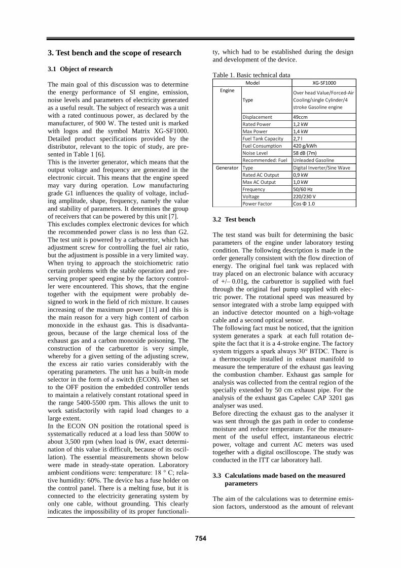
The main goal of this discussion was to determine
the energy performance of SI engine, emission,
noise levels and parameters of electricity generated
as a useful result. The subject of research was a unit
with a rated continuous power, as declared by the
manufacturer, of 900 W. The tested unit is marked
with logos and the symbol Matrix XG-SF1000.
Detailed product specifications provided by the
distributor, relevant to the topic of study, are pre-
sented in Table 1 [6].
This is the inverter generator, which means that the
output voltage and frequency are generated in the
electronic circuit. This means that the engine speed
may vary during operation. Low manufacturing
grade G1 influences the quality of voltage, includ-
ing amplitude, shape, frequency, namely the value
and stability of parameters. It determines the group
of receivers that can be powered by this unit [7].
This excludes complex electronic devices for which
the recommended power class is no less than G2.
The test unit is powered by a carburettor, which has
adjustment screw for controlling the fuel air ratio,
but the adjustment is possible in a very limited way.
When trying to approach the stoichiometric ratio
certain problems with the stable operation and pre-
serving proper speed engine by the factory control-
ler were encountered. This shows, that the engine
together with the equipment were probably de-
signed to work in the field of rich mixture. It causes
increasing of the maximum power [11] and this is
the main reason for a very high content of carbon
monoxide in the exhaust gas. This is disadvanta-
geous, because of the large chemical loss of the
exhaust gas and a carbon monoxide poisoning. The
construction of the carburettor is very simple,
whereby for a given setting of the adjusting screw,
the excess air ratio varies considerably with the
operating parameters. The unit has a built-in mode
selector in the form of a switch (ECON). When set
to the OFF position the embedded controller tends
to maintain a relatively constant rotational speed in
the range 5400-5500 rpm. This allows the unit to
work satisfactorily with rapid load changes to a
large extent.
In the ECON ON position the rotational speed is
systematically reduced at a load less than 500W to
about 3,500 rpm (when load is 0W, exact determi-
nation of this value is difficult, because of its oscil-
lation). The essential measurements shown below
were made in steady-state operation. Laboratory
ambient conditions were: temperature: 18 ° C; rela-
tive humidity: 60%. The device has a fuse holder on
the control panel. There is a melting fuse, but it is
connected to the electricity generating system by
only one cable, without grounding. This clearly
indicates the impossibility of its proper functionali-
ty, which had to be established during the design
and development of the device.
Table 1. Basic technical data
3.2 Test bench
The test stand was built for determining the basic
parameters of the engine under laboratory testing
condition. The following description is made in the
order generally consistent with the flow direction of
energy. The original fuel tank was replaced with
tray placed on an electronic balance with accuracy
of +/– 0.01g, the carburettor is supplied with fuel
through the original fuel pump supplied with elec-
tric power. The rotational speed was measured by
sensor integrated with a strobe lamp equipped with
an inductive detector mounted on a high-voltage
cable and a second optical sensor.
The following fact must be noticed, that the ignition
system generates a spark at each full rotation de-
spite the fact that it is a 4-stroke engine. The factory
system triggers a spark always 30° BTDC. There is
a thermocouple installed in exhaust manifold to
measure the temperature of the exhaust gas leaving
the combustion chamber. Exhaust gas sample for
analysis was collected from the central region of the
specially extended by 50 cm exhaust pipe. For the
analysis of the exhaust gas Capelec CAP 3201 gas
analyser was used.
Before directing the exhaust gas to the analyser it
was sent through the gas path in order to condense
moisture and reduce temperature. For the measure-
ment of the useful effect, instantaneous electric
power, voltage and current AC meters was used
together with a digital oscilloscope. The study was
conducted in the ITT car laboratory hall.
3.3 Calculations made based on the measured
parameters
The aim of the calculations was to determine emis-
sion factors, understood as the amount of relevant
XG-SF1000
Type
Over head Value/Forced-Air
Cooling/single Cylinder/4
stroke Gasoline engine
Displacement 49ccm
Rated Power 1,2 kW
Max Power 1,4 kW
Fuel Tank Capacity 2,7 l
Fuel Consumption 420 g/kWh
Noise Level 58 dB (7m)
Recommended: Fuel Unleaded Gasoline
Type Digital Inverter/Sine Wave
Rated AC Output 0,9 kW
Max AC Output 1,0 kW
Frequency 50/60 Hz
Voltage 220/230 V
Power Factor Cos Φ 1.0
Model
Engine
Generator
754
substances contained in the exhaust gas referred to
the sustained obtained electric energy and emission
factors referred to the mass of fuel consumed. The
useful result of the test is in this case electric power
output of the unit. Dry flue gas stream, and stream
of the specific components in the exhaust gases was
calculated based on the stoichiometric combustion
calculation, and the measured quantity of consumed
fuel. Using the exhaust gas composition analysis
the average ratio of the excess combustion air dur-
ing the measurement was determined. The compo-
sition of gasoline and its calorific value were adopt-
ed in accordance with literature data contained in
[8,9]. - 85% C; 15% -H (mass fractions); the calo-
rific value of 42,600 kJ / kg. The results were cor-
rected by the experimentally determined correction
taking into account the fuel evaporation from the
reservoir. The grid voltage bulbs were used as pow-
er receivers. In the analysis of the results only resis-
tive load character was adopted, which is consistent
with reality. Transmission cables were routed di-
rectly to the receivers using the shortest route.
Measuring instruments were included in the circuit
close to the output connector of the unit. The noise
generated by the unit measured at a distance of one
meter from the motor in many spatial directions
was in the range 79 - 83.2 dB(A) for speeds in the
range of 4000-5500 rpm covering the vast majority
of the generator field. This measurement was car-
ried out without the housing.
Emission factors Ei were calculated, meaning the
weight of expelled component relative to the
amount of mass of burned fuel. In the following
formulas 𝑖 is one of the respondent exhaust compo-
nents, which were: CO, CO2, HC.,
𝐸𝑖 = [𝑖] 𝑛′𝑐
[𝐶𝑂]+[𝐶𝑂2]+[𝐻𝐶] 𝑀𝑖 [
𝑔𝑖
𝑘𝑔𝑝𝑎𝑙.] (1)
where:
[𝑖] – the volume fraction of component in the dry
flue gas
𝑀𝑖,𝑔
𝑘𝑚𝑜𝑙 – the molar mass of exhaust component
𝑛′𝑐 ,𝑘𝑚𝑜𝑙
𝑘𝑔𝑝𝑎𝑙. – the molar amount of carbon in fuel
Emission factor ei identifying the expelled mass of
the component related to obtained useful effect, in
this case the electric power.
𝑒𝑖 = 𝑚𝑖˙
𝑁𝑒𝑙 [
𝑔𝑖
𝑘𝑊ℎ𝑒] (2)
where:
𝑚𝑖̇ ,𝑔𝑖
ℎ – the mass flow of the exhaust component
𝑁𝑒𝑙 , 𝑘𝑊 – the generated electric power, kW, calcu-
lated by multiplying the voltage and current.
𝑚𝑖̇ = 𝐸𝑖 𝑚𝑝̇
where:
𝑚𝑝̇ ,𝑘𝑔𝑝𝑎𝑙.
𝑠 – the mass fuel flow
Another calculated parameter was the efficiency of
the electricity generation.
𝜂𝑒𝑙 =𝑁𝑒𝑙
𝑊𝑑 𝑚𝑝̇ (3)
where:
𝑊𝑑 ,𝑘𝐽
𝑘𝑔 – the net calorific value of the fuel
3.4 Calculation related to usage as a vehicle
engine
The next stage of the calculation concerned the
application of the motor to drive the micro-vehicle.
It was made based on the shape of the body de-
signed by the team, which authors of this work are
members of. Needed values to calculation were
assumed in accordance with the experience based
on the participation of the faculty team in previous
editions of the competition: drag coefficient = 0.32
cx (obtained by CFD), the cross sectional area A =
1.2m2, the weight of the vehicle (including the
driver) m = 180kg, the rolling resistance coefficient
f = 0.005. The air density ρa = 1.2 kg/m3, density of
the fuel ρpal = 0.75 kg/dm3 [9]. According to the
rules of the contest, the minimum average speed is
23 km / h - the exact value assumed in the calcula-
tions, w = 6.39 m / s. Aerodynamic resistance was
defined as:
𝐹𝑎 = 𝑐𝑥 𝐴 𝜌𝑎 𝑤2
2 [𝑁] (4)
where:
𝑤,𝑚
𝑠 – the speed of the object relative to the fluid
𝑐𝑥 , − the drag coefficient 𝐴, 𝑚2 – the cross sectional area
𝜌𝑎,𝑘𝑔
𝑚3 – the air density
Rolling resistance was defined as:
𝐹𝑟 = 𝑚 𝑔 𝑓 𝑐𝑜𝑠𝛼 [𝑁] (5)
where:
𝑚, 𝑘𝑔 – the weight of the vehicle (including the
driver)
𝑓, − – the rolling resistance coefficient
𝑔,𝑚
𝑠2 – the gravitational acceleration
𝛼, ° – the angle of the track
The total resistance force for movement was calcu-
lated as the sum of the aerodynamic and rolling
resistance.
𝐹𝑟 + 𝐹𝑎 = 𝐹𝑜𝑟 [𝑁] (6)
The power of motion resistance, taking into account
the vehicle speed was calculated.
755

𝐹𝑜𝑟 𝑤 = 𝑁𝑜𝑟 [𝑊] (7)
Distance possible to drive using one litre of fuel
was determined assuming that the running track is
flat, that is perpendicular to the force of gravity (α =
0). Furthermore, it was assumed that the efficiency
of the transmission is equal to the efficiency of the
electricity generating system. Indices were calculat-
ed as emissions per kilometer.
𝑒𝑑 = 𝑁𝑜𝑟
𝑤 𝑒𝑖 [
𝑔𝑖
𝑘𝑚] (8)
The excess of the power needed to overcome the
hill was calculated as well as the power needed to
achieve assumed acceleration.
𝐹𝑤 = 𝑚 𝑔 𝑠𝑖𝑛𝛼 [𝑁]
𝑁𝑤 = 𝐹𝑤 𝑤 [𝑊] (9)
where:
𝑁𝑤 , 𝑊 – the power to overcoming the slope angle α
𝐹𝑤, 𝑁 – the climbing resistance force
𝑁𝑝 = 𝑚 𝑎 𝑤 [𝑊] (10)
where:
𝑁𝑝, 𝑊 – the excess of power in order to accelerate
𝑎,𝑚
𝑠2 – assumed instantaneous acceleration
4. Research results and calculations
4.1 Parameters that characterize the work of the
unit:
Figures 1-3 below presents the results of emission
factors of the individual exhaust components.
Fig. 1. Summary of CO emission factors for ECON
mode ON / OFF
Fig. 2. HC emission factors ECON mode ON / OFF
Fig. 3. NOx emission factors for the ECON mode
ON / OFF
In addition to these values also the temperature in
the exhaust manifold was determined.
Fig. 4. Exhaust gas temperature dependence of load
on the device
The following figures illustrate the parameters
characterizing the energy conversion process.
Fig. 5. Specific fuel consumption in relation to the
load in both modes
756

Fig. 6. Efficiency of electricity generation by the
generator
Fig. 7. Relation between the fuel air ratio and elec-
tric power
Voltage inverter system maintained by the ECON
mode set to OFF remained in the range of 220-
230V for the power consumption of no more than
700W. Further increase in load resulted in a signifi-
cant decrease in voltage, and therefore it was not
possible to obtain an output of more than 750 W.
On ECON mode ON, the maximum achievable
power was similar, but voltage in a stable operating
range was lower - 210-220V.
Built-in anti-overload circuit activated on the cur-
rent flow of approximately 4.0A (contrary to 4.4A
written on the script placed on the housing). This
would give the maximum power declared by the
manufacturer, if the voltage would be maintained at
appropriate level. The maximum power of the unit,
providing stable and satisfactory electrical parame-
ters to operate most consumer devices was 700W.
Determined power of motion resistance, taking into
account assumed speed, and the sum of rolling and
aerodynamic drag, is about 120W (7).
𝑁𝑜𝑟 ≅ 120𝑊
The efficiency of the unit at the point where it gen-
erates the output of 100 W was about 3.5% at
ECON mode set to on (3). It is assumed that the
transmission efficiency of the vehicle is equal to the
efficiency of the part generating electricity. Accord-
ing to the assumptions, the distance travelled on
one litre of fuel will be about 80km.
The above considerations are valid for steady state,
constant speed, without taking into account wind
and other factors that may occur. Calculations were
made of the required excess of the power (without
taking into account resistance of motion Nor) in
order to obtain a specific acceleration at a speed of
23 km / h (10). Table 3 presents the results of these
calculations.
Table 3. The power required to obtain the specific
accelerations at a speed of 23 km/h
a [m/s2] Np [W]
0,1 115
0,2 230
0,3 345
0,4 460
0,5 575
0,6 690
Table 4 presents the excess of power Nw needed to
overcome the hill depending on the slope expressed
by angle of inclination α at a constant speed of 23
km/h (9).
Table 4. The required power needed to overcoming
the hill at a speed of 23 km / h
α [deg] Nw [W]
1 197
2 394
3 590
4 787
Table 5 Shows the emission of harmful substances
by a vehicle referred to the distance travelled while
driving on a flat road at a speed of 23 km/h.
Table 5. Road emissions of selected exhaust com-
ponents at a speed of 23 km/h
Component 𝑒𝑑 [g/100km]
CO 378
CO2 2331
HC 49
NOx 8
5. Conclusions
On the basis of calculated values for the tested
power generator it has been stated that the unit
meets the emission standards established by the
European Commission and United States Environ-
mental Protection Agency. There is significant
impact on the efficiency of the unit (3) according to
electrical load among others due to the throttling
method of adjustment. There are noticeable differ-
757

ences in efficiency depending on the working mode
of the unit (ECON ON / OFF).
Emissions of harmful components related to the
electric power decreased with increasing load, the
only exception was the nitrogen oxides. The course
of the curve describing them in Figure 3 and the
temperature of the exhaust gas in the exhaust mani-
fold in Figure 4 show some convergence. The in-
creasing concentration of nitrogen oxides was due
to the temperature increase which was due to con-
siderable loads close to the maximum. Another
factor contributing to the formation of nitrogen
oxides concentration at high level (obtained during
the field test) was the excess of air fuel ratio air
[11]. During operation, the generator on ECON
ON mode for load below 200W instability was
observed. This situation corresponds to the rotation
of less than 4400 rpm. Simultaneously the engine
misfire was observed, which is the reason of high
fuel air ratio together with poor quality of combus-
tion process. This was also seen as a significant
increase in CO and HC emissions. These phenome-
na can be seen in Figures 1 and 2. In all measure-
ments the CO was at a high level. As mentioned
earlier the unit usually operates in the field of rich
mixtures. At the same time oxygen contained in the
exhaust gas was observed to be about 0.5% for
loads higher than 200W.
One of the possible solutions aimed at improving
the efficiency of the tested engine is to control the
ignition timing. Together with the more efficient
algorithm of controlling the throttle it is suspected
that this would increase engine efficiency, reduce
vibration and reduce emissions.
Modifications of the supply system such as re-
placement carburettor by injection system, which
provided a significant reduction in CO and HC in
the exhaust gas, have been analysed by previous
researchers [10].
Currently control system supported by the LPT port
of the computer and microcontroller is being devel-
oped.
Calculations for use in micro vehicle were made.
Estimated distance possible to drive on one liter of
fuel was about 80 km. This result was compared
with the results from the previous years of the Shell
Eco-marathon competition. The results are at the
last or one of the last places. During a continuous
movement, with the assumed speed on flat terrain,
about 10% of the tested engine maximum power is
used.
These values do not take account of the planned
modification. Achievable maximum acceleration
and grade ability go beyond the demands of the
competition. Therefore another engine with less
power was proposed - eg. Honda GX-35.
Acknowledgements:
This work was supported by the project: “Competent mechanical engineers for energy sector”, POKL.04.01.02-
00-131/12, implemented at the Silesian University of Technology.
Bibliography
[1] D. Sa´ inz, P.M. Die´guez, C. Sopena 1, J.C.
Urroz, L.M. Gandı´a, Conversion of a
commercial gasoline vehicle to run bi-fuel
(hydrogen-gasoline), International Journal of
Hydrogen Energy, vol. 37, pp. 1781 -1789,
2012.
[2] Ju Suk Byun, Jungsoo Park, Predicting the
performance and exhaust NOX emissions of a
spark-ignition engine generator fuelled with
methane based biogases containing various
amounts of CO2, Journal of Natural Gas
Science and Engineering, vol. 22, pp. 196-202,
2015.
[3] Liangzhu Wang, Steven J. Emmerich, Andrew
K. Persily, Cheng-Chun Lin, Carbon monoxide
generation, dispersion and exposure from
indoor operation of gasoline-powered electric
generators under actual weather conditions,
Building and Environment, vol. 56, pp. 283-
290, 2012.
[4] European Commission, Non-Road mobile
machinery emissions [online], Directives
97/68/EC - 2012/46/EU, available of
08.04.2015.
Access online:
http://ec.europa.eu/growth/sectors/automotive/
environment-protection/non-road-mobile-
machinery/index_en.htm
[5] US Environmental Protection Agency, Nonroad
Spark-Ignition Engines 19 Kilowatts and
Below -- Exhaust Emission Standards [online],
available of 14.05.2015.
Access online:
http://www.epa.gov/otaq/standards/nonroad/sm
allsi-exhaust.htm
[6] Yongkang Changheng Tools Co., Ltd., Product
Detail, Digital Inverter Generator (XG-
SF1000) Access online: http://cnchangheng.en.made-in-
758
china.com/product/KoeErkIMEYcd/China-
Digital-Inverter-Generator-XG-SF1000-.html [7] Norbert Broniek, Agregaty Prądotwórcze
[online], Porady Fachowego Elektryka,
available of 10.04.2015.
Access online:
http://www.epssystem.pl/pdf/agregaty.pdf
[8] Jan Szargut, Termodynamika, Wydanie 7,
Warszawa, Wydawnictwo Naukowe PWN,
2012, ISBN 978-83-01-13086-2.
[9] Właściwości benzyny bezołowiowej 95
Eurosuper produkowanej przez PKN ORLEN
S.A [online], ORLEN PetroTank, available of
10.04.2015. Access online: http://www.orlen-
petrotank.pl/PL/PolitykaJakosci
[10] Adrian Irimescu, Gabriel Vasiu, Gavrila Trif
Tordai, Performance and emissions of a small
scale generator powered by a spark ignition
engine with adaptive fuel injection control,
Applied Energy, vol. 121, pp. 196–206, 2014.
[11] Sławomir Luft, Podstawy budowy silników,
Wydanie 2, Warszawa, Wydawnictwo
Komunikacji i Łączności, 2006, ISBN 83-206-
1629
Buczkowski Daniel – Student of Silesian
University of Technology at the Faculty of
Energy and Environmental Engineering.
email: [email protected]
Buchalik Ryszard – Student of Silesian
University of Technology at the Faculty of
Energy and Environmental Engineering.
email: [email protected]
Grzegorz Przybyła, PhD. – Faculty of
Power and Environmental Engineering, Silesian University of Technology, Gliwice,
Poland. email: [email protected]
759