Embed Size (px)
Citation preview

VARDHAMAN COLLEGE OF ENGINEERING
STRENGTH OF MATERIALS LAB 1
LABORATORY MANUAL
STRENGTH OF MATERIALS
DEPARTMENT OF
CIVIL ENGINEERING
VARDHAMAN COLLEGE OF ENGINEERING (Autonomous)
(Permanently Affiliated to JNTUH, Approved by AICTE, New Delhi & Accredited by NBA)
Shamshabad – 501218, Hyderabad.

VARDHAMAN COLLEGE OF ENGINEERING
STRENGTH OF MATERIALS LAB 2
LIST OF EXPERIMENTS:
1) Tension test 5
2) Bending test on (Steel / Wood) Cantilever beam. 9
3) Bending test on simple support beam. 11
4) Impact test 13
5) Spring test 17
6) Torsion test 20
7) Hardness test 21
8) Compression test on wood or concrete 28
9) Verification of Maxwell’s Reciprocal theorem on beams. 30
10) Shear test 31
11) Use of electrical resistance strain gauges 33

VARDHAMAN COLLEGE OF ENGINEERING
STRENGTH OF MATERIALS LAB 3
MANDATORY INSTRUCTIONS
1. Students should report to the labs concerned as per the timetable.
2. Record should be updated from time to time and the previous experiment must be
signed by the faculty in charge concerned before attending the lab.
3. Students who turn up late to the labs will in no case be permitted to perform the
experiment scheduled for the day.
4. After completion of the experiment, certification of the staff in-charge concerned in
the observation book is necessary.
5. Students should bring a notebook of about 100 pages and should enter the
readings/observations/results into the notebook while performing the experiment.
6. The record of observations along with the detailed experimental procedure of the
experiment performed in the immediate previous session should be submitted and
certified by the staff member in-charge.
7. Not more than FIVE students in a group are permitted to perform the experiment on
a set up.
8. The group-wise division made in the beginning should be adhered to, and no mix up
of student among different groups will be permitted later.
9. The components required pertaining to the experiment should be collected from
Lab- in-charge after duly filling in the requisition form.
10. When the experiment is completed, students should disconnect the setup made by
them, and should return all the components/instruments taken for the purpose.
11. Any damage of the equipment or burnout of components will be viewed seriously
either by putting penalty or by dismissing the total group of students from the lab
for the semester/year.
12. Students should be present in the labs for the total scheduled duration.
13. Students are expected to prepare thoroughly to perform the experiment before
coming to Laboratory.
14. Procedure sheets/data sheets provided to the students groups should be maintained
neatly and are to be returned after the experiment.

VARDHAMAN COLLEGE OF ENGINEERING
STRENGTH OF MATERIALS LAB 4
15. DRESS CODE:
i. Boys - Formal dress with tuck in and shoes.
ii. Girls - Formal dress (salwar kameez).
Iii. Apron in blue color for both boys and girls.
iii. Wearing of jeans is strictly prohibited

VARDHAMAN COLLEGE OF ENGINEERING
STRENGTH OF MATERIALS LAB 5
EXPERIMENT NO: 01
TENSION TEST
AIM: - To conduct tension test on a mild steel bar to find its
(i) Yield stress (ii) ultimate stress (iii) breaking stress (iv) percentage elongation (v)
percentage reduction in area of cross section and (vi) Young's modulus of Elasticity for
steel material.
APPARATUS: -Tension testing machine (5 to 400 KN capacity); vernier calipers, and
extensometer.
GENERAL : The two essential parts of a testing machine are
(i) a means for applying load to specimen and
(ii) a means for measuring the applied load. In addition to these basic features there
are a variety of, accessory parts such as those for gripping or supporting 'the test
pieces, controllers, recorders, speed indicators and shock absorbers.
The load may be applied by mechanical means through these of screw-gear
mechanism in which case the machines are referred to as hydraulic jack; the machine is
called a hydraulic machine. Some machines are designed for one kind of test only such
as compression or tension. However if a machine is designed to test a specimen in
tension, compression, flexure, ahanr etc., it is called universal testing machine. (U. T
.M)
DESCRIPTION: - In the tension testing machine, the load is applied through the use of
screw-gear mechanism. The machine consists of base and vertical channels, which
support the load measuring unit. The base houses the drive unit. The drive is affected
by an eccentric motor whose stroke is transmitted through set of pulleys to the spindle.
Load can also be applied manually by rotating loading wheel: when pull is applied to
specimen, the pendulum gets deflected from its vertical position in proportion to pull
applied and the tensile force is indicated on the dial by the drag pointer. To record the
curve of the test, the machine is equipped with autographic recorder. To prevent
sudden fall of the pendulum rod on rupture of the specimen, the damping unit is
provided which ensures that thependulul1l red slowly goes back to its vertical position.
When the pendulum rod falls back, the drag pointer rod remains in its position to'
indicate maximum strength developed during the strength.
The machine has three loading ranges, 1 ton, 2.5 ton, and 5 ton. Attaching
weight discs, on the pendulum rod sets, the measuring ranges.
0 – 1.0 ton = disc A
0 - 2.5ton =>discs A+B+C

VARDHAMAN COLLEGE OF ENGINEERING
STRENGTH OF MATERIALS LAB 6
0 -5.0 ton => discs A+B+C+D+E+F
The autographic recorder consists of an aluminum drum on which a graph paper
is wound. Curve is drawn with a pen connected to the pendulum rod through rack.
On drum, the tensile force is recorded on horizontal axis and the elongation is
recorded in the direction of vertical axis. If the graph paper is taken off and turned
by'90 degrees, the curves are obtained in the usual representation i.e. load on y-axis
and extension on x-axis.
PROCEDURE:
(1) Considering the breaking strength of the test specimen select a proper loading
range out of the three ranges provided on the machine. Place suitable weight discs on
the pendulum at the back of the machine.
(2) Depending on the dimensions of the test specimen, appropriate gripping jaws
should be installed in grip housing.
(3) Measure the diameter of the specimen and mark gauge length accurately.
(4) Fix the specimen in the center of grips. Fix the extensometer to the specimen.
(5) Set drag pointer and dial gauges in extensometer to zero.
(6) Note the elongation reading for each suitable increment to load until the specimen
yields. The yielding of the specimen is observed from the fast movement of the
extensometer needle for no increment of load. At this stage extensometer is removed.
The load increases gradually and reaches a maximum value called ultimate load. After'
reaching the ultimate load, specimen breaks. Note this breaking load.
The readings may be tabulated in a tabular form as shown below.
TABULATION: -
S.No
Load
applied
In kg
Extensometer reading Stress
in Kq/cm2 Strain
E in
Kg/cm2 In div In cm

VARDHAMAN COLLEGE OF ENGINEERING
STRENGTH OF MATERIALS LAB 7
Using stress strain values, stress strain curve is drawn. Young's modulus of
Elasticity is calculated from the graph.
Load at yield point in kg from graph =
Yield stress in kg/cm2 = Load at yield point / original c/s area
Ultimate load in kg =
Ultimate stress in kglcm2 = Ultimate load / original c/s area
Breaking load in kg =
Breaking stress in kg/om2 = Breaking Load / original c/s area
% Elongation = Change in length x 100 / Original length
% Reduction in area of cross section = A - Al x 100
A
A - Initial area of c/s
Al - Area of c/s at the broken section =
Least Count of vernier calipers = 0.002,
TABULATION FOR MEASUREMENT OF DIAMETER: -
Trail No Main scale reading
in cm
M.S.R
Vernier scale
coincidence in div
V.S.C
Diameter = M.S.R + L.C x
V.S.C in cm

VARDHAMAN COLLEGE OF ENGINEERING
STRENGTH OF MATERIALS LAB 8
Average diameter in cm =
RESULT: The ultimate strength of given test specimen is_______N/mm2.

VARDHAMAN COLLEGE OF ENGINEERING
STRENGTH OF MATERIALS LAB 9
EXPERIMENT NO: 02
CANTILEVER BEAM
AIM: Determination of young’s modulus of the material cantilever beam.
APPARATUS: Cantilever beam, hanger with weights deflection gauge, vernier calipers
and meter scale.
PROCEDURE:
(1) Measure the dimension of the beam i.e. the length ‘L’ the distance between the
face of fixed support and the free end, width ‘b’ and depth ‘d’.
(2) Fix the dial gauge at the free end of the beam for measuring the deflection with the
needle just touching the bottom of the beam
(3) Place the hanger at a measured distance ‘L1’ from the fixed support. Record reading
on the dial gauge. Successively place the additional weight on the hanger. Record the
reading of the dial gauge when each weight is added.
(4) Repeat experiment by decreasing the weights and tabulated the reading.
S.No Load
Applied
Dial gauge reading Deflection =
Avg. Loading
in Div x L.C
Young’s
modulus
E=
N/mm2 Kg N During
loading
in Div
During
unloading
in Div
Average
loading in
Div
Calculations:
The young’s modulus of the beam is calculated using the formula given below
δ = WL13+WL1
2(L- L1)
3EI 2EI

VARDHAMAN COLLEGE OF ENGINEERING
STRENGTH OF MATERIALS LAB 10
Applying the above formula, the value of ‘E’ is
E = WL13+WL1
2(L- L1 )
3 δ I 2 δ I
Where I = Moment of the inertia of the cross section of the beam = bd3 mm4
12
Observation: Length of the beam L =
Width of the beam b =
Depth of the beam d =
Distance of the load W from the fixed end, L1 =
NOTATION: -
A - Fixed support
B - Free end (At this point dial gauge should be fixed to measure deflection)
L - Length of the span (The distance between the face affixed support and the free end)
W - Load applied
L1 - The distance of the load from the fixed support
RESULT: Young’s modulus of Elasticity ‘E’ of the material of the beam is
_______N/mm2.

VARDHAMAN COLLEGE OF ENGINEERING
STRENGTH OF MATERIALS LAB 11
EXPERIMENT NO: 03
SIMPLY SUPPORTED BEAM
AIM: Determination of Young’s Modulus of the material simply supported beam.
APPARATUS: Simply supported beam, hanger with weights, deflection gauge, vernier calipers
and meter scale
PROCEDURE:-
1. Measure the dimension of the beam i.e. the length 'L’ the between knife edge supports,
width 'b' and depth‘d’
2. Fix the dial gauge at the center of the beam for measuring deflection. The needle of the
dial gauge should touch the bottom of the beam.
3. Place the hanger at a measured distance L1 from any support. Record reading on the dial
gauge. Successively place the additional weight is added. Record the reading of the dial
gauge when each weight is added.
4. Repeat experiment by decreasing the weights and tabulated the reading.
S.No Load Applied Dial gauge reading Deflection =
Avg. loading
in Div x L.C
Young’s
modulus E
= N/mm2
Kg N During
loading
in Div
During
unloading
in Div
Average
loading
in Div
Calculations:
The formula for deflection ‘δ’ at the centre for the ‘w’ applied at a distance ‘a’ from one
and is δ = WL3
48EI

VARDHAMAN COLLEGE OF ENGINEERING
STRENGTH OF MATERIALS LAB 12
Moment of inertia of the cross section of the beam, ‘I’ = bd3 mm4
12
Applying the above formula, the value of ‘E’ is E = WL3
48δI
Notation:
A – Left support
B – Right Supported
L – Length of the spam
W – Load applied.
RESULT: Young’s modulus of Elasticity ‘E’ of the material of the beam is ______N/mm2.

VARDHAMAN COLLEGE OF ENGINEERING
STRENGTH OF MATERIALS LAB 13
EXPERIMENT NO: 04
IMPACT TEST- IZOD
AIM: To conduct Izod Impact Test on a given specimen to determine the toughness of
the material of the specimen.
APPARATUS: Impact testing machine, 10x10 square specimen, vernier calipers
DESCRIPTION OF THE MACHINE: The machine combines the facility for performing
different standard impact tests such as
1. Izod Test
2. Charpy Test.
The materials, which can be tested on this machine, include Steel, Copper, Brass and
Alloys.
MACHINE SPECIFICATIONS: Machine has the fallowing ranges
(a) 307.6 J for Charpy impact test and
(b) 164.6 J for Izod impact test.
The machine has a pendulum of specified weight and effective length of O.8I5m.
For each of the test, the appropriate grips and striking tool have to be used.
The test essentially consists of holding the specimen at the at the position with proper
grip, raising the pendulum through a specified angle releasing it to strike the specimen
to cause fracture and measuring the energy lost in breaking the specimen. The energy
lost is directly read on the dial.
TECHNICAL DATA:
Weight of the pendulum = 20.59 kg.
Angle of drop pendulum = 900
Effective length of pendulum = 0.815 m
Energy at impact = 20.59 x 9.81 x 0.815 x (1- Cos 90°) = 164.6 J
The dial is gradated to read directly the energy lost at impact.
SPECIMEN FOR IZOD TEST: Izod specimen made out of 10 mm square has V-notch of
2mm depth with included angle of 45° at the section where it is required to fracture by
impact.
PROCEDURE:
1. Keep the pendulum in its initial position and lock it.
2. Fix the proper striker firmly to the pendulum.

VARDHAMAN COLLEGE OF ENGINEERING
STRENGTH OF MATERIALS LAB 14
3. Keep the specimen in position in such a way that the notch on the specimen facing
the pendulum.
4. Release the pendulum and note down the reading of the pointer on the dial which is
the energy absorbed by the specimen at fracture.
EVALUATION TEST: The impact strength of the specimen is given by I=K/A
Where, K = the energy absorbed by the specimen
A = Area of cross section of the specimen below the notch, m2
PRECAUTIONS:
1. Before releasing the pendulum, students should make sure that nobody is
standing in the swing zone of the pendulum.
RESULT: 1. Energy absorbed by the specimen at fracture is______ J.
2. Impact strength of the specimen is________ J/mm2.

VARDHAMAN COLLEGE OF ENGINEERING
STRENGTH OF MATERIALS LAB 15
EXPERIMENT NO: 05
IMPACT TEST – CHARPY
AIM: To conduct Charpy Impact Test on a given specimen to determine the toughness
of material of the specimen.
APPARATUS: Impact testing machine, 10x10 square specimen, vernier calipers
DESCRIPTION OF THE MACHINE:
The machine combines the facility for performing different
Standard impact tests such as 1. Izod Test
2. Charpy Test.
The materials that can be tested on this machine include Steel, Copper, Brass and
Alloys.
MACHINE SPECIFICATIONS: Machine has the fallowing ranges.
(a) 307.6 J for Charpy impact test and
(b) 164.6 J for Izod impact test.
The machine has a pendulum of specified weight and effective length of
0.815m. For each of the test, the appropriate grips and striking tool have to be used.
The test essentially consists of holding the specimen at the at the position with
proper grip, raising the pendulum through a specified angle releasing it to strike the
specimen to cause fracture and measuring the energy lost in breaking the specimen.
The energy lost is directly read on the dia1.
Technical data:
Weight of the pendulum = 21.79 kg.
Angle of drop of pendulum = 140°
Effective length of pendulum = 0.815111
Energy at impact = 21.79 x 9.81 x 0.815 x (1- Cos 140°) = 307.6
The dial is graduated to read directly the energy lost at Impact.
SPECIMEN FOR CHARPY TEST: Specimen for charpy is made out of 10 mm square rod
having V -notch of 2mm depth with included angle of 45° at the section where it is
required to fracture by impact.
PROCEDURE:
1. Keep the pendulum in its initial position and lock it.

VARDHAMAN COLLEGE OF ENGINEERING
STRENGTH OF MATERIALS LAB 16
2. Fix the proper striker firmly to the pendulum.
3. Place the specimen on specimen support touching end stop. The specimen should be
placed in such a way that the notch on the specimen is averted to the direction of
impact of the pendulum.
4. Release the pendulum and note down the reading of the pointer on the dial which is
the energy absorbed by the specimen at fracture.
EVALUATION TEST: The impact strength of the specimen is given by I=K/A
Where, K = the energy absorbed by the specimen, J
A = Area of cross section of the specimen below the notch, m2
PRECAUTIONS:
1. Before releasing the pendulum, students should make sure that nobody is
standing in swing zone of the pendulum.
RESULT: 1. Energy absorbed by the specimen at fracture is______ J.
2. Impact strength of the specimen is________ J/mm2.

VARDHAMAN COLLEGE OF ENGINEERING
STRENGTH OF MATERIALS LAB 17
EXPERIMENT NO: 06
SPRING TEST
AIM: To determine the modulus of rigidity of material of the spring.
APPARATUS: Spring testing machine, spring, Vernier.
THEORY: Springs are elastic members, which distort under load and regain their original
shape when load is removed. They are used in railway carriages, motorcars, scooters,
motorcycles, rickshaws, governors etc.
DIFFERENT TYPES OF SPRINGS:
1. Closely - coiled springs &Tension helical springs
2. Open-coiled springs & Compression springs
3. Full- elliptical leaf springs.
4. Semi - elliptical leaf springs.
5. Cantilever leaf springs
6. Circular springs.
Depending on their use, springs perform the following functions:
1. Absorb shock or impact loading as in carriage springs.
2. Store energy as in Clock springs.
3. Supply forces to and to control motions as in brakes and clutches
4. Measure forces as in spring balance.
5. Absorb the vibrations.
Springs are usually made of either High carbon steel (0.7% to 1.0%) or Medium
carbon alloy steels, Phosphor bronze, Brass and 18/8 Stainless steel. Other metal alloys
are also used for corrosion resistance.
Deflection of a closely - coiled spring of circular cross section is given by,
δ = 8 W D3 n / Gd4
Where W = Load applied on the spring,
D = Mean diameter of the coil of the spring,
d = Diameter of the spring wire,

VARDHAMAN COLLEGE OF ENGINEERING
STRENGTH OF MATERIALS LAB 18
n = Number of turns of the spring coil,
G = Modulus of rigidity of the spring material.
PROCEDURE:
1. Measure the Mean diameter (D) of the coil and wire diameter (d) of the
spring using Vernier calipers.
2. Count the number of turns (n) of the spring
3. Insert the spring in the two jaws of the spring testing machine
4. Apply the load slowly with the help of handle until the spring deflects by say 5mm
and note down the load on the respective dial corresponding to the pendulum load
setup.
5 .Repeat the experiment and tabulate the readings.
OBSERVATIONS: Mean diameter of the coil of the spring, D =
Diameter of the spring wire, d =
No. of turns of the spring, n =
Tabular Column:
S.No Load W Deflection,
δ in mm
Stiffness
K = W/δ
Modulus of
rigidity,
G = 8 WD3 n/δd4
N Kg

VARDHAMAN COLLEGE OF ENGINEERING
STRENGTH OF MATERIALS LAB 19
Calculations: The rigidity modulus of the spring material is calculated as follows:
G = 8 WD3 n/δd4
PRECAUTIONS:
1. Take the reading from the scale corresponding to the set pendulum weight.
2. Apply the load gradually.
3. Remove the load carefully and remove the spring.
RESULT: Average rigidity modulus of the spring material is ___________ N/mm2.

VARDHAMAN COLLEGE OF ENGINEERING
STRENGTH OF MATERIALS LAB 20
EXPERIMENT NO: 07
TORSION TEST
AIM: To determine the Modulus of rigidity of the material of the given specimen using
torsion testing machine.
APPARATUS: Torsion testing machine, specimen, vernier calipers.
PRINCIPLE: When a straight circular bar of a given material is subjected to a torque 'T',
the angle of twist 'θ' in radians over a length 'L' of the bar is given by
θ = (T x L) / (G x J)
Where J = Polar moment of inertia = (П d4)/ 32
DESCRIPTION OF THE MACHINE: The torsion testing machine consists of two sturdy
stands on which the base frame is firmly fixed. The driving chuck is fixed on base frame
to the left end of the machine, torque indicator and the stationary chuck is fixed on the
right end of machine. The torque applied by the motor or hand wheel is transferred to
the pendulum, which in turn gets deflected. A dummy pointer (red) is provided on the
dial to indicate the amount of torque required for breaking the specimen A dash pot is
provided in the dynamometer panel which serves for slow release of load when the
specimen breaks. An angle-measuring disc is provided to facilitate the measurement of
angle of twist.
PROCEDURE:
1. Measure the diameter and length of the specimen.
2. Adjust the pendulum weight and corresponding range on the dial according to the
specimen to be tested.
3. Fix one end of the specimen in the driving chuck.
4. Move the trolley towards, the fixed chuck and fix the other end of the specimen.
5. Adjust the angle measuring disc and the torque-measuring dial to zero.
6. Apply the torque by rotating the hand wheel. Note down the value of the torque for
each 10 of the angle of twist.
7. Repeat the step 6 and take five readings.
8. Tabulate the readings.
RESULT: Modulus of rigidity of the material______________

VARDHAMAN COLLEGE OF ENGINEERING
STRENGTH OF MATERIALS LAB 21
EXPERIMENT NO: 08
ROCKWELL HARDNESS TEST
AIM: To determine the hardness number of different materials such as Steel, Brass and
Copper.
APPARATUS: Rockwell hardness testing machine, Specimen, Allen key, Indentor.
THEORY: Hardness of material is the property by virtue of which it offers resistance to
indentation or penetration or abrasion by other bodies. Hardness can be measured in
following ways.
1. Scratch hardness
2. Rebound hardness-Shore'scleroscope
3. Penetration hardness-Vickers, Rockwell and Brinnel.
Penetration hardness is the one, which is determined in this test. The test
essentially consists of first applying a small or minor load on the specimen through an
indentor. A major load is then added to the minor load and is allowed to act on the
indentor. The dashpot arrangement provided in the machine enables slow application
of the load with out shock or impact .The load will cause both plastic and elastic
deformation on the specimen. When the major load is removed, there is a recovery of
elastic deformation and the plastic deformation in the specimen is a measure of its
hardness, though the actual mode of measuring the hardness defers from method to
method.
DESCRIPTION OF MACHINE: The machine has a cast iron body and has a small platform
over which the test specimen is placed. The plat form is supported by a cylindrical stem,
which has a screw out side. The stem and the platform can be fixed in a centralized
position. The dial gauge, which is mounted in the front of the machine, is in contact
with the loading lever and gives the indentation or penetration of the indentor on the
specimen.
There are two types of indentors supplied with the machine.
1. 1/16 inch (l.5875mm) diameter steel ball indentor.
2. Diamond type indentors with 120° cone angle.
The total 1oad to be applied varies with type of indentor. In all the tests the
initial or minor load is 10 kg. This can be applied by raising the flat form using the hand
wheel so that the indicator presses the specimen that causes the deflection of the dial
gauge pointer. The hand wheel is rotated until the large and small pointers of dial
VARDHAMAN COLLEGE OF ENGINEERING
STRENGTH OF MATERIALS LAB 22
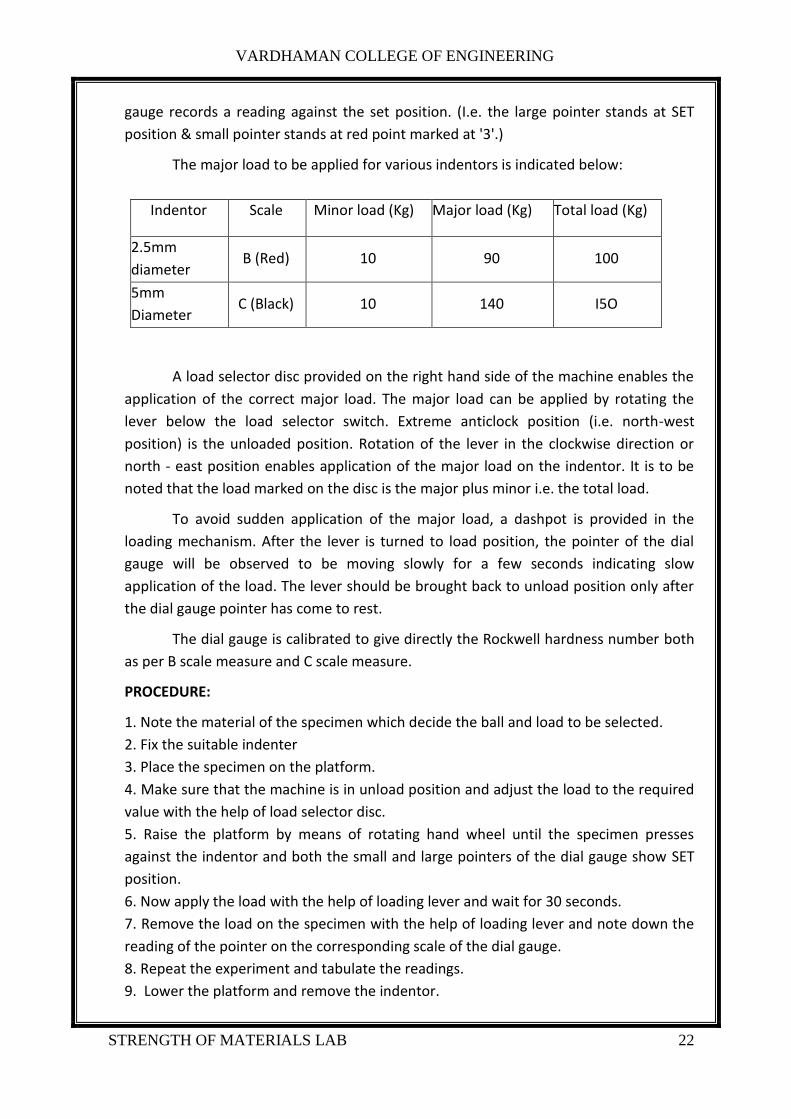
gauge records a reading against the set position. (I.e. the large pointer stands at SET
position & small pointer stands at red point marked at '3'.)
The major load to be applied for various indentors is indicated below:
Indentor Scale Minor load (Kg) Major load (Kg) Total load (Kg)
2.5mm
diameter B (Red) 10 90 100
5mm
Diameter C (Black) 10 140 I5O
A load selector disc provided on the right hand side of the machine enables the
application of the correct major load. The major load can be applied by rotating the
lever below the load selector switch. Extreme anticlock position (i.e. north-west
position) is the unloaded position. Rotation of the lever in the clockwise direction or
north - east position enables application of the major load on the indentor. It is to be
noted that the load marked on the disc is the major plus minor i.e. the total load.
To avoid sudden application of the major load, a dashpot is provided in the
loading mechanism. After the lever is turned to load position, the pointer of the dial
gauge will be observed to be moving slowly for a few seconds indicating slow
application of the load. The lever should be brought back to unload position only after
the dial gauge pointer has come to rest.
The dial gauge is calibrated to give directly the Rockwell hardness number both
as per B scale measure and C scale measure.
PROCEDURE:
1. Note the material of the specimen which decide the ball and load to be selected.
2. Fix the suitable indenter
3. Place the specimen on the platform.
4. Make sure that the machine is in unload position and adjust the load to the required
value with the help of load selector disc.
5. Raise the platform by means of rotating hand wheel until the specimen presses
against the indentor and both the small and large pointers of the dial gauge show SET
position.
6. Now apply the load with the help of loading lever and wait for 30 seconds.
7. Remove the load on the specimen with the help of loading lever and note down the
reading of the pointer on the corresponding scale of the dial gauge.
8. Repeat the experiment and tabulate the readings.
9. Lower the platform and remove the indentor.

VARDHAMAN COLLEGE OF ENGINEERING
STRENGTH OF MATERIALS LAB 23
S.No. Specimen Indentor Load Scale Used R.H.N
PRECAUTIONS:
1. The hand load must be applied only when the loading lever is in un-load position
2. The pointer in the smaller should not cross the red spot (Le. '3') during the
application of primary or hand load.
RESULT: The average RHN of the specimen is _________

VARDHAMAN COLLEGE OF ENGINEERING
STRENGTH OF MATERIALS LAB 24
EXPERIMENT NO: 09
BRINNEL HARDNESS
AIM: To determine the Brinnel hardness number of the given materials such as Steel,
Brass and Copper.
APPARATUS: Brinnel hardness testing machine, Microscope, Specimen, Allen key,
Indentor.
THEORY: Hardness of material is the property by virtue of which it offers resistance to
indentation or penetration or abrasion by other bodies. Hardness can be measured in
fallowing ways.
1. Scratch hardness
2. Rebound hardness-Shore'scleroscope
3. Penetration hardness-Vickers, Rockwell and Brinnel.
Penetration hardness is the one, which is determined in this test. The test
essentially consists of first applying a small 0r minor load on the specimen through an
indicator. A major load is then added to the minor load and is allowed to act on the
indenter. The dashpot arrangement provided in the machine enables slow application
of the load without shock or impact. Hardness in the case of Rockwell test is directly
based on the depth of plastic deformation under the major load. Also it depends on the
load and type of indenter used. This is not the case with Brinnel hardness test.
Brinnel Hardness Number (B.H.N) = PIA
Where, P= Total load applied in kg,
A = Surface area of the indentation measured in mm2
Only hard steel balls of diameter ranging from 1 mm to 10 mm are used as indentors.
For the same material same B.H.N value will be obtained irrespective of the total load
and indentor diameter used. Usual diameters of indentors used in practice are of
2.5mm, 5mm, and 10mm. The standard combinations of load and the diameter of the
ball that may be used on various materials are indicated below.
S.NO PD2 Ratio Representative material
1 30 Steel, Cast iron
2 10 Copper alloys
3 60 to 20 Copper, Aluminium

VARDHAMAN COLLEGE OF ENGINEERING
STRENGTH OF MATERIALS LAB 25
4 Less than 20 Lead, Tin and their alloys
The loads to be selected for different indentors are calculated as follows:
Example 1: Let the specimen made of Steel.
If D = 10mm, desirable value of P = 30 X 102= 3000 kg.
IfD = 2.5 mm, desirable value of P = 30 x 2.52 = 187.5 kg.
Example 2: Let the specimen made of copper alloy.
If D = 5mm, desirable value of P = 10 X 52 = 250 kg.
DESCRIPTION OF MACHINE: The machine has a cast iron body and has a small platform
over which the test specimen is placed. The plat form is supported by a cylindrical stem,
which has a screw out side. The stem and the platform can be fixed in a centralized
position. The dial gauge, which is mounted in the front of the machine, is in contact
with the loading lever and gives the indentation or penetration of the indentor on the
specimen.
There are two types of indentors supplied with the machine.
1. 2.5 mm diameter steel ball indentor.
2. 5 mm diameter steel ball indentor
The total load to be applied differs with indentor. In all the tests the initial or
minor load is 10 kg. This can be applied by raising the flat form using the hand wheel so
that the indicator presses the specimen that causes the deflection of the dial gauge
pointer. The hand wheel is rotated until the large and small pointers of dial gauge
records a reading against the set position. (Le. the large pointer stands at SET position
& small pointer stands at red point marked at '3'.)
Indentor P/D2
Ratio
Load. P
(kg)
2.5mm diameter 30 187.5
5mm Diameter 10 250
A load selector disc provided on the right hand side of the machine enables the
application of the correct major load. The major load can be applied by rotating the
lever below the load selector switch. Extreme anticlock position (i.e. north-west
position) is the unloaded position. Rotation of the lever in the clockwise direction or
north - east position enables application of the major load on the indentor. It is to be
noted that the load marked on the disc is the major plus minor i.e. the total load.

VARDHAMAN COLLEGE OF ENGINEERING
STRENGTH OF MATERIALS LAB 26
To avoid sudden application of the major load a dashpot is provided in the
loading mechanism. After the lever is turned to load position, the pointer of the dial
gauge will be observed to be moving slowly for a few seconds indicating slow
application of the load. The lever should be brought back to unload position only after
the dial gauge pointer has come to rest.
PROCEDURE:
l. Note the material of the specimen which decide the ball and load to be selected.
2. Fix the suitable indenter
3. Place the specimen on the platform.
4. Make sure that the machine is in unloading position and adjust the load to the
required value with the help of load selector disc.
5. Raise the platform by means of rotating hand wheel until the specimen presses
against the indenter and both the small and large pointers of the dial gauge show SET
position.
6. Apply the load with the help of loading lever and wait for 30 seconds.
7. Now unload the machine and take the specimen out.
8. Measure the diameter‘d’ of the indentation using Brinnel Microscope
9. Repeat the experiment and tabulate the readings.
S.No. Specimen
Load
Applied
(kg)
Diameter of
the
indentor
D in mm
Diameter of
the
indentation
d in mm
Surface area of
Indentation in mm2
A=ПD[D-√D2 –d2 ]
B·H.N

VARDHAMAN COLLEGE OF ENGINEERING
STRENGTH OF MATERIALS LAB 27
Precautions:
1. The hand load must be applied only when the loading lever is in un-load position
Result: The average B.H.N of the specimen is _____________

VARDHAMAN COLLEGE OF ENGINEERING
STRENGTH OF MATERIALS LAB 28
EXPERIMENT NO: 10
COMPRESSIVE STRENGTH ON BRICK
AIM: To determine the compressive strength of a given test sample by compression testing
machine.
APPARATUS: Compression testing machine, test sample brick, steel rule, vernier calipers.
DESCRIPTION:
1. The machine is designed for testing red bricks, cement concrete cubes and
cylinders.
2. The load is applied through a adjustable hydraulic assembly.
3. The loader platen is on the hydraulic ram and the upper having a spherical seating
is adjustable hydraulic assembly.
4. The machine is provided with an air release valve and the load is automatically
indicated on a hydraulic pressure gauge reading 0-100Tonnes.
PROCEDURE:
1. Place the test sample to be tested on the bottom platen centering it with the
help of guidelines provided on bottom platen.
2. Close the release valve tight in clockwise direction.
3. Bring the central screw operating the handle such bthat the palten is in contact
with the top of the test specimen.
4. Place the hand operating lever on the pumping unit .
5. When operate the handle up and down, with this the hydraulic ram rises
gradually, thus compressing the test sample.
6. Simultaneously the pointers of the pressure gauge progress gradually on the dial.
7. When the sample breaks, the red pointer of the pressure gauge stays put at the
load where the sample breaks and the black pointer comes back to ‘0’.
8. The load indicated by the red pointer is the breaking load of the test sample.
9. Open the release valve for the hydraulic ram to settle down.
10. Calculate the compression strength of the test sample by the formula.
Compressive strength= breaking load/ Area of the test sample
11. Remove the test sample and restart a fresh test.
TABULAR COLOUMN:
S.N0. AREA OF CROSS
SECTION(mm2)
BREAKIN LOAD (N) COMPRESSIVE STRENGTH
(N/mm2)

VARDHAMAN COLLEGE OF ENGINEERING
STRENGTH OF MATERIALS LAB 29
OBSERVATIONS:
Material used=
Name of the cross section=
Compressive strength (Fc)= Breaking load (P) / Cross sectional area
PRECAUTIONS:
1. Keep the machine clean and free dust, dirty etc.
2. Frequently check the hydraulic oil level in the pumping unit.
3. After every test, remove fragments of the test sample.
NOTE:
1. The cross sectional area of cylinder test sample A= (π/4)*D2
2. Cross sectional area of sample (A)= Length* Width
RESULT: The compressive strength of the given test sample is________ N/mm2.

VARDHAMAN COLLEGE OF ENGINEERING
STRENGTH OF MATERIALS LAB 30
EXPERIMENT NO: 11
VERIFICATION OF MAXWELL’S RECIPROCAL THEOREM
AIM: To verify the Maxwell’s reciprocal theorem on simply supported beam.
APPARATUS: Beam of one meter, dial gauge, steel rule.
THEORY: Maxwell reciprocal theorem states that the deflection at point B is same when the
load applied at B.
PROCEDURE:
1. The beam is bended between the supports.
2. Mark the lengths L/4, L/2, 3L/4 on the beam plane the weight at L/4 and dial gauge
at 3L/4.
3. The loads are loaded in the hanger and deflections are found in the dial guage.
4. Now the dial guage is placed at L/4 and the weight at 3L/4.
5. Readings are noted down.
TABULAR COLOUMN:
DEFLECTION AT L/4
S.NO LOAD DEFLECTION WHILE
LOADING
DEFLECTION WHILE
UNLOADING
DEFLECTION AT 3L/4
S.NO LOAD DEFLECTION WHILE
LOADING
DEFLECTION WHILE
UNLOADING
PRECAUTIONS:
1. The loads and dialguage are placed carefully.
2. While under loading the deflection gauge should be at zero.
3. Avoid external loads and needless vibrations.
RESULT: The Maxwell’s reciprocal theorem on simply supported beam is verified.

VARDHAMAN COLLEGE OF ENGINEERING
STRENGTH OF MATERIALS LAB 31
EXPERIMENT NO: 12
SHEAR TEST
AIM: -To determined Shear Test of Steel.
APPARATUS:
1. Universal testing machine.
2. Shear test attachment.
3. Specimens.
THEORY: Place the shear test attachment on the lower table, this attachment consists of
cutter. The specimen is inserted in shear test attachment & lift the lower table so that the
zero is adjusted, then apply the load such that the specimen breaks in two or three pieces. If
the specimen breaks in two pieces then it will be in single shear & if it breaks in three pieces
then it will be in double shear.
PROCEDURE:
1. Insert the specimen in position and grip one end of the attachment in the upper
portion and one end in the lower portion.
2. Switch on the main switch of universal testing machine machine.
3. The drag indicator in contact with the main indicator.
4. Select the suitable range of loads and space the corresponding weight in the
pendulum and balance it if necessary with the help of small balancing weights.
5. Operate (push) buttons for driving the motor to drive the pump.
6. Gradually move the head control level in left-hand direction till the specimen
shears.
7. Down the load at which the specimen shears.
8. Stop the machine and remove the specimen
OBESERVATION:
Diameter of the Rod, D = ….. mm
Cross-section area of the Rod (in double shear) = 2x π/4X D2 =.. mm2
Load taken by the Specimen at the time of failure , W = N
Strength of rod against Shearing = ƒx2x π/4X D2 ƒ =W / 2X π/4X D2 N/mm2
PRECAUTION:
1. The measuring range should not be changed at any stage during the test.
2. The inner diameter of the hole in the shear stress attachment should be slightly

VARDHAMAN COLLEGE OF ENGINEERING
STRENGTH OF MATERIALS LAB 32
greater than that of the specimen.
3. Measure the diameter of the specimen accurately.
RESULT: The Shear strength of mild steel specimen is found to be……………… N/mm2

VARDHAMAN COLLEGE OF ENGINEERING
STRENGTH OF MATERIALS LAB 33
EXPERIMENT NO: 13
TYPES OF STRAIN GAUGES
AIM: To Study various types of strain Gauges.
THEORY : A strain Gauge may be defined as any instrument or device that is employed to
measure the linear deformation over a given gauge length, occurring in the material of a
structure during the loading of structures. This definition is quite broad. In fact it covers the
range of instruments included between the linear scale & the precise optical & electrical
gauges now available. The many types of strain gauges available are quite varied both in
applications & in the principle invalid in their magnification, systems. Depending upon the
magnification system the strain gauges may be classified as follows:
1) Mechanical
1. Wedge & screw
2. Lever - simple & compound
3. Rock & pinion
4. Combination of lever & rack & pinion
5. Dial indicators
2) Electrical
1. Inductance
2. Capacitance
3. Piezoelectric & piezoresiotue
Accuracy & repeatability -: Sensitive does not ensure accuracy. Usually the very sensitive
instruments are quite prone to error unless they are employed with utmost care. Before
selecting a particular type of gauge following factors must also be carefully evaluated.
1) Readalutity
2) Ease of mounting
3) Required operator skill
4) weight
5) frequency response
6) cost.

VARDHAMAN COLLEGE OF ENGINEERING
STRENGTH OF MATERIALS LAB 34
Mechanical Strain Gauges:-
Wedge & screw orignification:-
The wedge gauge is simply a triangular plate with its longer sides related at 1:10 slope when
inserted between two shoulders dipped to the test specimen, extension could be detected
nearest 0.05 mm .A single screw extensometer which is one of the pioneer instruments
used for measurement of strain. The magnification in this instrument is accomplished solely
by a screw micrometer a measures the relative motion of two coaxial tubes
1. Magnetic
2. Acoustical
3. Pneumatic
4. Scratch type
5. Photo stress
Characteristic of a strain gauge:-
A strain gauge has the following four basic characteristics
1. Gauge length: - The gauge size for a mechanical strain gauge is characterized by the
distance between two knife edges in contact with the specimen & by width of a movable
knife edges non linear strum which should be as small as possible in that case.
2. Sensitivity: It is the smallest value of strain which can be read on the scale associated
with strain gauge .Sensitivity can be defined in two way
Smallest reading of scale
i) Deformation sensitivity = ------------------------------------
Multiplication factor
Deformation sensitivity
ii) Strain sensitivity = ------------------------------------
Base length
Range: - This represents the maximum strain which can be recorded without resetting or
replacing the strain gauge. The range & sensitivity are
1) Simple Mechanical lever magnification:-
VARDHAMAN COLLEGE OF ENGINEERING
STRENGTH OF MATERIALS LAB 35
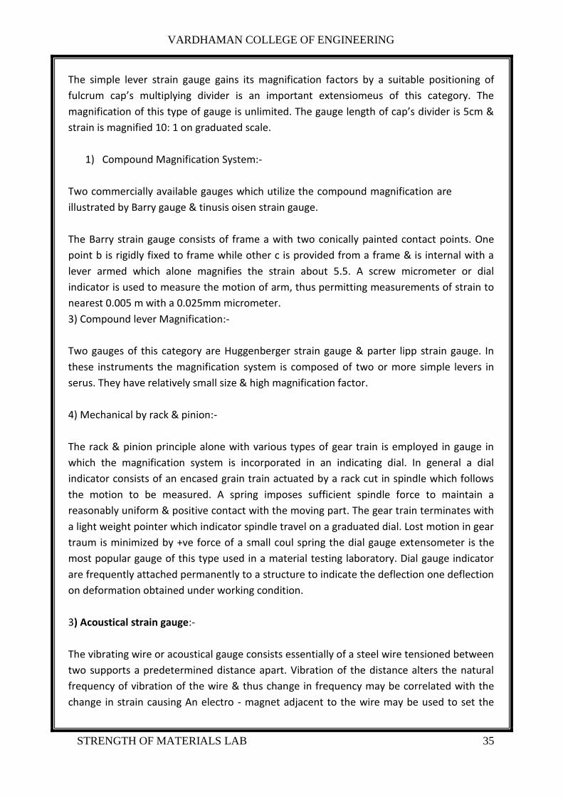
The simple lever strain gauge gains its magnification factors by a suitable positioning of
fulcrum cap’s multiplying divider is an important extensiomeus of this category. The
magnification of this type of gauge is unlimited. The gauge length of cap’s divider is 5cm &
strain is magnified 10: 1 on graduated scale.
1) Compound Magnification System:-
Two commercially available gauges which utilize the compound magnification are
illustrated by Barry gauge & tinusis oisen strain gauge.
The Barry strain gauge consists of frame a with two conically painted contact points. One
point b is rigidly fixed to frame while other c is provided from a frame & is internal with a
lever armed which alone magnifies the strain about 5.5. A screw micrometer or dial
indicator is used to measure the motion of arm, thus permitting measurements of strain to
nearest 0.005 m with a 0.025mm micrometer.
3) Compound lever Magnification:-
Two gauges of this category are Huggenberger strain gauge & parter lipp strain gauge. In
these instruments the magnification system is composed of two or more simple levers in
serus. They have relatively small size & high magnification factor.
4) Mechanical by rack & pinion:-
The rack & pinion principle alone with various types of gear train is employed in gauge in
which the magnification system is incorporated in an indicating dial. In general a dial
indicator consists of an encased grain train actuated by a rack cut in spindle which follows
the motion to be measured. A spring imposes sufficient spindle force to maintain a
reasonably uniform & positive contact with the moving part. The gear train terminates with
a light weight pointer which indicator spindle travel on a graduated dial. Lost motion in gear
traum is minimized by +ve force of a small coul spring the dial gauge extensometer is the
most popular gauge of this type used in a material testing laboratory. Dial gauge indicator
are frequently attached permanently to a structure to indicate the deflection one deflection
on deformation obtained under working condition.
3) Acoustical strain gauge:-
The vibrating wire or acoustical gauge consists essentially of a steel wire tensioned between
two supports a predetermined distance apart. Vibration of the distance alters the natural
frequency of vibration of the wire & thus change in frequency may be correlated with the
change in strain causing An electro - magnet adjacent to the wire may be used to set the

VARDHAMAN COLLEGE OF ENGINEERING
STRENGTH OF MATERIALS LAB 36
wire in vibration & this wire movement will then generate on oscillating electrical signal .
The signal may be compared with the pitch adjustable standard wire , the degree of
adjustment necessary to match of two signal frequencies being provided by a tensioning
screw on the slandered wove calibration of this screw allows direct determination of
change of length of a measuring gauge to be made once the standard gauge has been tuned
to match the frequency of measuring wire.
The visual display produced is a cko renders adjustment easier. Tuning is now more usually
accomplished by feeding the two signal in to two pours of plates of an oscillogram & making
use of the luscious figure formation to balance the frequencies. Matching of tones is
simplified & made more accurate.
The fundame
1 p p e l A
f = ----- ---- ---- -----
2 L m 2l L
A = Cross sectional area
E = Young’s modulus of were
h = length of vibrating were
m = mass per unit length of were
p = tensioning force is were
w = increment in length of vibrating were