Embed Size (px)
Citation preview

LABORATORY MANUAL OF ENGINEERING MECHANICS LAB
Sr. No. Experimental Title
1 Verification of reciprocal theorem of deflection using a simply
supported beam
2 Deflections of a truss -horizontal de flections & vertical deflections of
various joints of a pin-jointed truss
3 Elastic displacements (vertical & horizontal) of curved members
4 Experimental and analytical study of 3 hinged arch and influence line for
horizontal thrust
5 Experimental and analytical study of behavior of struts with
various end conditions
6 To determine elastic properties of a beam
7 Experiment on a two-hinged arch for horizontal thrust & influence line
for Horizontal thrust
8 Experimental and analytical study of deflections for unsymmetrical
bending of a Cantilever beam

OBJECTIVE: Verification of reciprocal theorem of deflection using a simply
supported beam.
Requirements: 1. Model of a simply supported beam 2. Dial gauge
3. Weights
4. Steel scale
Theory:
Maxwell theorem in its simplest form states that deflection of any point A of
any elastic structure due to load P at any point B is same as the deflection of beam due
to same load applied at A. It is, therefore easily derived that the deflection curve for a
point in a structure is the same as the deflected curve of the structure when unit
load is applied at the point for which the influence curve was obtained.
Layout Diagram:
A B C D
X Y
A B C D
X’ Y
’
’

Procedure:
1. Apply a load either at the centre of the simply supported span or at the free end of the
beam, the deflected form can be obtained.
2. Measure the height of the beam at certain distance by means of a dial gauge before and
after loading and determine the deflection before and after at each point separately.
3. Now move a load along the beam at certain distance and for each positions of the load,
the deflection of the point was noted where the load was applied in step1. This deflection
should be measured at each such point before and after the loading, separately.
4. Plot the graph between deflection as ordinate and position of point on abscissa the plot
for graph drawn in step 2 and 3. These are the influence line ordinates for deflection of
the beam.
Observation Table :
Results:
∆c =∆d` ∆d==∆c`
Conclusion:
Reciprocal theorem is verified.

Precautions:
i. Apply the loads without any jerk.
ii. Perform the experiment at a location, which is away from any external disturbance.
iii. Ensure that the supports are rigid.
iv. Gently tap the dial gauge before observing the readings.
OBJECTIVE: Deflections of a truss -horizontal deflections & vertical deflections of
various joints of a pin-jointed truss.
Requirements: 1. Truss Apparatus. 2. Weights, 3. Hanger. 4. Dial Gauge, Scale. 5. Vernier caliper.
Theory: The deflection of a node of a truss under a given loading is determined by: δ = Σ (TUL/AE)
Where, δ = deflection at the node point. T = Force in any member under the given loading.
U = Force in any member under a unit load applied at the point where the deflection is
required. The unit load acts when the loading on the truss have been removed and acts in the same direction in which the deflection is required. L = Length of any member. A = Cross sectional area of any member. E = Young’s modulus of elasticity of the material of the member.
Here, (L/AE) is the property of the member, which is equal to its extension per unit load. It may be determined for each member separately by suspending a load from it and noting the extension.
Layout Diagram:

Procedure: 1. Detach each spring from the member. Plot extension against load by suspending load from
the spring and nothing the extension. From the graph, obtain the extension per unit load (stiffness).
2. For initial position of the truss, load each node with 0.5 kg load to activate each member.
Now place the dial gauges in position for measuring the deflections and note down the initial
reading in the dial gauges. 3. Also put additional load of 1kg, at L1, 2kg, L2, and 1kg at L3, and note the final reading in
the dial gauges. The difference between the two readings will give the desired deflection at the nodal points. Central deflection y. 4. Calculate the deflection for the three nodes L1, L2, and L3 from the formula given in Eq. (1)
and compare the same with the experimental values obtained in step 3. 5. Draw the Willot - Mohr diagram for deflection and compare the deflection so obtained experimentally and analytically.
Observation Table :
Experimental Deflection Values
S.No. Node Deflection L1 L2 L3
1 Initial dial gauge
reading ( mm )
2 Additional loads
( kg )
3 Final dial gauge
Reading ( mm )
4 Deflection (3) - (1)
(mm)
Results: The theoretical and experimental deflection in various members is found same.
Precautions:
i. Apply the loads without any jerk.
ii. Measure the deflection to the nearest of a millimeter. iii. Perform the experiment at a location, which is away from any external disturbance.
iv. Ensure that the supports are rigid.

OBJECTIVE: Elastic displacements (vertical & horizontal) of curved members
Requirements:
The apparatus consists of a steel bar which is used as different curved members’ viz.
circle, semi circle with straight arm, quadrant of a circle and quadrant of a circle with straight
arm. The bottom ends of the members are fixed to the base to impart rigidity to the structures.
Under the application of a load at free end its horizontal and vertical deflection is measured with
the help of a dial gauges.
Theory:
The theorem used to find elastic displacement is the Castiglione’s First Theorem which
states that ‘Partial derivative of the total strain in energy of a structure with respect to any force
gives the displacement of the point of its application in the direction of the force. The total strain
energy of the structure is determined in terms of all other loads with their actual values and a
fict itious load at the point at which the deflection is required acting in the direction of the
deflection. After particle differentiation with respect to P, the actual value (if P is an actual load) of
zero is substituted for P. The result is the deflection required
Layout Diagram:
a. Quadrant of a circle :
Fixed at A and free at B (radius R) and subjected to a concentrated load W at free end.

b. Quadrant with a straight leg
From A to B, quadrant of a circle of radius R, from B to C straight length
c. Semi circle with straight arm
From A to C semi circle of radius R, A to B straight length of y

Procedure:
1. Place an init ial load of 200gm on the hanger. Fix the dia l gauge for horizontal and
vertical deflections. Set the dial gauge to zero. Assume this position as initial.
2. Add load at the following rates and tabulate the values of the dial gauge readings.
3. In the cases of quadrant, quadrant with straight arm and semi circle, 200gm steps and in
the case of circle, 1kg steps.
4. Measure the vertical displacement in y-axis and the horizontal displacement in x-axis for
each loading positions.
5. Repeat the process for desired no. of times for different set of loads.
6. Measure the same parameters for unloading the weights.
Observation Table :

Result: Measure the value of R and straight length in each case. Find width and breadth of steel
section and calculate the value of I.
Precautions:
i. Apply the loads without any jerk.
ii. Perform the experiment at a location, which is away from any external dis turbance.
iii. Ensure that the supports are rigid.
iv. Gently tap the dial gauge before observing the readings.
v. The load applied should be within the allowed limits for the apparatus.

OBJECTIVE: Experimental and analytical study of 3 hinged arch and influence
line for horizontal thrust.
Requirements:
A three hinged arch is statically determined with the axial thrust assisting in maintaining
the stability. The model has a span of 100cm and rise of 25cm with hinges at supports and
crown. One of the ends rests on rollers along the horizontal span of the applications of load. This
marked at the equidistant for the application of load. This being a statically determined structure,
the horizonta l thrust developed under the action of any load system can be theoretically
calculated and will also be measured directly by neutralization of the outward movement of the
roller end.
Theory:

Layout Diagram:
Procedure: 1. Balance the self weight of the arch by putting load on the thrust hanger till the
appropriate equilibrium conditions are obtained. The moveable end of the arch is
positioned such that it shows a tendency to move inside on tapping the supporting table.
2. Place a few loads on the arch in any chosen positions. Balance these by placing additional
weights on the hanger for horizontal thrust. The additional weights on the thrust hanger
give the experimental value of the horizontal thrust.
3. Measure the distances a1, a2 and a3 from A with respect to the loads applied, W1, W2
and W3.
Observation Table:
Observations:
Span of the arch, L =
Central rise, r =
Initial load on the thrust hanger for balancing=

Result: Compare the horizontal thrust obtained theoretically with the values obtained
experimentally.
Precautions:
i. Apply the loads without any jerk.
ii. Perform the experiment at a location, which is away from any external disturbance.
iii. Ensure that the supports are rigid.
iv. The load applied should be within the allowed limits for the apparatus.
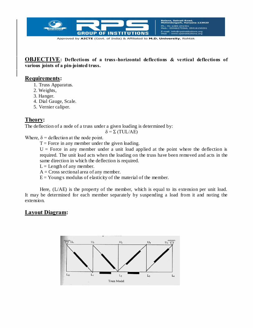
OBJECTIVE: Experimental and analytical study of behavior of struts with various end
conditions.
Requirements:
Apparatus consists of four spring steel columns, which are put along a vertical wooden
board. These four columns have different end conditions as below:
1. Both ends pinned
2. Both ends fixed
3. One end pinned and other fixed
4. One end fixed and other end free
Layout Diagram:
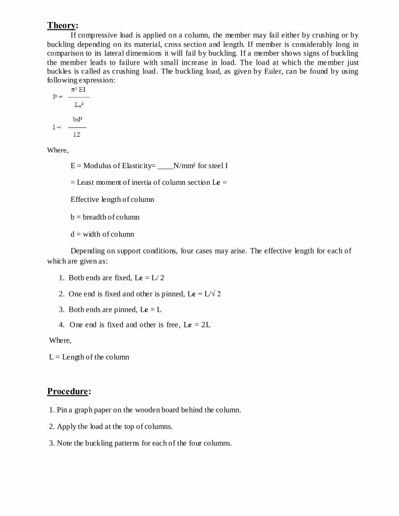
Theory: If compressive load is applied on a column, the member may fail either by crushing or by
buckling depending on its material, cross section and length. If member is considerably long in comparison to its lateral dimensions it will fail by buckling. If a member shows signs of buckling
the member leads to failure with small increase in load. The load at which the member just buckles is called as crushing load. The buckling load, as given by Euler, can be found by using following expression:
Where,
E = Modulus of Elasticity= ____N/mm² for steel I
= Least moment of inertia of column section Le =
Effective length of column
b = breadth of column
d = width of column
Depending on support conditions, four cases may arise. The effective length for each of
which are given as:
1. Both ends are fixed, Le = L/ 2
2. One end is fixed and other is pinned, Le = L/√ 2
3. Both ends are pinned, Le = L
4. One end is fixed and other is free, Le = 2L
Where,
L = Length of the column
Procedure:
1. Pin a graph paper on the wooden board behind the column.
2. Apply the load at the top of columns.
3. Note the buckling patterns for each of the four columns.

4. Trace the deflected shapes of the columns over the graph paper. Mark the points of change of
curvature of the curves and measure the effective or equivalent length for each case separately.
5. Calculate the theoretical effective lengths and thus buckling loads by the expressions given
above and compare them with the observed values
Observation:
Result:
1. Calculate the buckling load for each case
2. Study the shape of the curve and the points of buckling traced at the graph paper

OBJECTIVE: To determine elastic properties of a beam
Requirements:
The apparatus consists of a flexible beam supported by two rigid supports equally distant
from the ends of the beam. This set up provides two over hangs at the ends of the beam. The beam
has notches separated by 0.1 meter distance. Two hangers are provided at the free ends of the beam
to suspend the loads at the ends.
Layout Diagram:
Theory:
We know that
Where,
a = length of overhang on each side
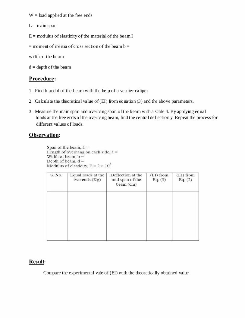
W = load applied at the free ends
L = main span
E = modulus of elasticity of the material of the beam I
= moment of inertia of cross section of the beam b =
width of the beam
d = depth of the beam
Procedure: 1. Find b and d of the beam with the help of a vernier caliper
2. Calculate the theoretical value of (EI) from equation (3) and the above parameters.
3. Measure the main span and overhang span of the beam with a scale 4. By applying equal
loads at the free ends of the overhang beam, find the central deflection y. Repeat the process for
different values of loads.
Observation:
Result:
Compare the experimental vale of (EI) with the theoretically obtained value

Precautions:
i. Apply the loads without any jerk.
ii. Perform the experiment at a location, which is away from any external disturbance.
iii. Ensure that the supports are rigid.
iv. The load applied should be within the allowed limits for the apparatus
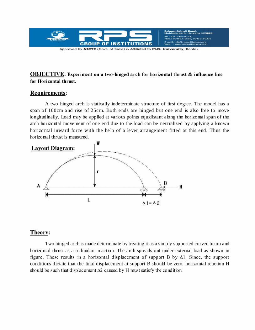
OBJECTIVE: Experiment on a two-hinged arch for horizontal thrust & influence line
for Horizontal thrust.
Requirements:
A two hinged arch is statically indeterminate structure of first degree. The model has a
span o f 100cm and rise of 25cm. Both ends are hinged b ut one end is also free to move
longitudinally. Load may be applied at various points equidistant along the horizontal span of the
arch horizontal movement of one end due to the load can be neutralized by applying a known
horizontal inward force with the he lp of a lever arrangement fitted at this end. Thus the
horizontal thrust is measured.
Layout Diagram:
Theory:
Two hinged arch is made determinate by treating it as a simply supported curved beam and
horizontal thrust as a redundant reaction. The arch spreads out under external load as shown in
figure. These results in a horizontal displacement of support B by ∆1. Since, the support
conditions dictate that the final displacement at support B should be zero, horizontal reaction H
should be such that displacement ∆2 caused by H must satisfy the condition.
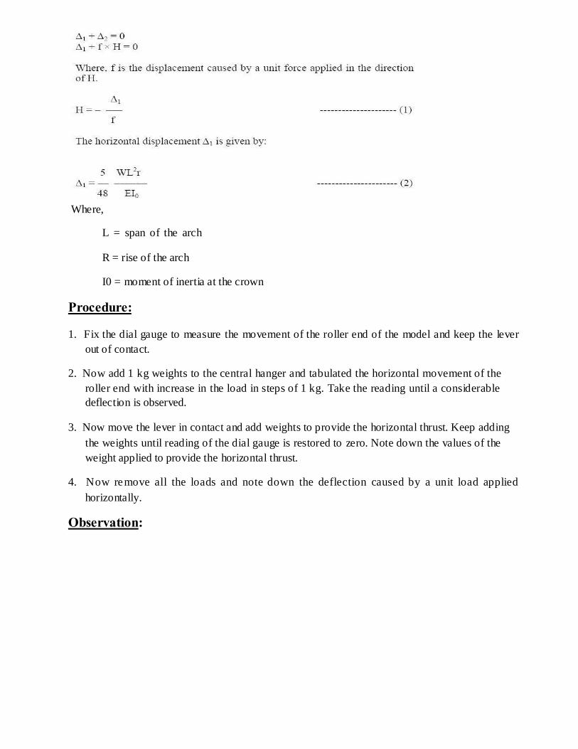
Where,
L = span of the arch
R = rise of the arch
I0 = moment of inertia at the crown
Procedure:
1. Fix the dial gauge to measure the movement of the roller end of the model and keep the lever
out of contact.
2. Now add 1 kg weights to the central hanger and tabulated the horizontal movement of the
roller end with increase in the load in steps of 1 kg. Take the reading until a considerable
deflection is observed.
3. Now move the lever in contact and add weights to provide the horizontal thrust. Keep adding
the weights until reading of the dial gauge is restored to zero. Note down the values of the
weight applied to provide the horizontal thrust.
4. Now remove all the loads and note down the deflection caused by a unit load applied
horizontally.
Observation:

Result:
Compare and analyze the value of horizontal thrust observed with the values obtained
theoretically.
Precautions:
i. Apply the loads without any jerk.
ii. Perform the experiment at a location, which is away from any external disturbance.
iii. Ensure that the supports are rigid.
iv. The load applied should be within the allowed limits for the apparatus.

OBJECTIVE: Experimental and analytical study of deflections for unsymmetrical bending
of a Cantilever beam.
Requirements:
The apparatus consists of an angle of size 1"×1"×1/8" or in equivalent metric units of
length 80cm is tied as a cantilever beam. The beam is fixed at one end such that the rotation of 45º
intervals can be given and clamped such that the principle axis of its cross section may be inclined
at any angle with the horizontal and vertical planes.
Also arrangement is provided to apply vertical load at free end of the cantilever and to measure
horizontal and vertical deflection of the free end.
Layout Diagram:
Theory:
One of the basic assumptions in deriving the flexural formula F = My/I is that the plane
of load is perpendicular to the neutral axis. Every cross-section has got two mutually
perpendicular principle axis of inertia, about one of which he moment of inertia is the maximum
and about the other a minimum. In can be shown that a symmetrical axis of cross section is one
of the principle axis and one at right angles to the same will be the other principle axis.

For beams having unsymmetrical cross section such as angle (L) or channel (I) sections, if the
place of loading is not coincident with or parallel to one of the principle axis, unsymmetrical or
non-uniplaner bending.
In this experiment for a cantilever beam, the plane of loading is always kept vertical and the angle
iron cantilever beam itself is rotated through angles in steps of 45°.
Procedure:
1. Clamp the beam at zero position and suspend a 500gm load from the hanger and take this as
zero loading on the beam to activate the member.
2. Attach and adjust the d ia l gauge at the free end to measure vert ica l and hor izonta l
displacements.
3. Load the beam in steps of 1kg up to 3kg and each time note down the deflection.
4. Apply the loads gradually without jerk.
5. Repeat steps 1 to 4 turning the beam through 45º intervals.
6. Plot a graph for the deflection observed against the load applied. Ideally the graph should
produce a straight line.
Observation:

Result:
Study the pattern of bending of the beam with the help of the graph
Precautions:
i. Apply the loads without any jerk.
ii. Perform the experiment at a location, which is away from any external disturbance.
iii. Ensure that the supports are rigid.
iv. Gently tap the dial gauge before observing the readings.
v. The load applied should be within the allowed limits for the apparatus.