Embed Size (px)
Citation preview
Experiment 1
Laboratory Hardware and Tools
Each day, our lives become more dependent on ‘embedded systems’, digital information tech-
nology that is embedded in our environment. Try making a list and counting how many devices
with embedded systems you use in a typical day. Here are some examples: if your clock radio
goes off, and you hit the snooze button a few times in the morning, the first thing you do in your
day is interact with an embedded system. Heating up some food in the microwave oven and
making a call on a cell phone also involve embedded systems. That is just the beginning. Here
are a few more examples: turning on the television with a hand held remote, playing a hand
held game, using a calculator, and checking your digital wristwatch. All those are embedded
systems devices that you interact with.
Exponentially increasing computing power, ubiquitous connectivity and the convergence of tech-
nology have resulted in hardware/software systems being embedded within everyday products
and places. The last few years has seen a renaissance of hobbyists and inventors building
custom electronic devices. These systems utilize off-the-shelf components and modules whose
development has been fueled by a technological explosion of integrated sensors and actuators
that incorporate much of the analog electronics which previously presented a barrier to system
development by non-engineers. Microcontrollers with custom firmware provide the glue to bind
sophisticated off-the-shelf modules into complex custom systems.
What are Embedded Systems?
Embedded systems are combination of hardware and software combined together to perform
a dedicated task. Usually, they are used to control a device, a process or a larger system.
Some examples of embedded systems include those controlling the structural units of a car,
the automatic pilot and avionics of aircraft, telematic systems for traffic control, the chipset
and software within a set-top box for digital TV, a pacemaker, chips within telecommunication
switching equipment, ambient devices, and control systems embedded in nuclear reactors. The
block diagram of embedded system is shown in Figure 1.1
Lab Objective
Development of an embedded system requires that combination of both hardware and software
components should perform their assigned tasks under the predefined circumstances. This
lab provides a series of experiments aimed at teaching hardware interfacing and embedded
4

5
Microcontroller
Processor
RAM
ROM ADC
I/O Ports
Bus
DACAnalog
Signals
Chemical
Electrical,
Mechanical,
or Other
devices
Embedded System
Figure 1.1: Block diagram of an embedded system
programming skills. We follow the bottom up approach by starting with simpler tasks and
gradually building on that to develop a complete embedded system.
Prerequisites for Lab
This lab is designed for the students having some experience in ‘C’ programming, but no prior
experience with embedded systems. In this lab, we assume that you have basic understanding
of digital logic design and analog electronics.
Hardware Required
Hardware required for the experiments in this lab is listed below:
1. Stellaris Launchpad Board based on LM4F120H5QR microcontroller
2. Expansion Board based on different electronic components required to perform lab assign-
ments.
Stellaris Launchpad Board
The key component used in the tutorials is the Stellaris Launchpad board produced by Texas In-
struments (TI). The board, illustrated in Figure 1.2, includes a user configurable LM4F120H5QR
micro-controller with 256 KB flash and 32 KB RAM as well as integrated circuit debug interface
(ICDI). With appropriate software running on the host it is possible to connect to the LM4F120
processor to download, execute and debug user code.
In Figure 1.2, there is a horizontal white line slightly above the the midpoint. Below the line are
the LM4120H5QR, crystal oscillators, user accessible RGB LED, user accessible push-buttons
and a reset push button. Above the line is the hardware debugger interface including a 3.3V

6 CHAPTER 1. LABORATORY HARDWARE AND TOOLS
Power SelectSwitch Green Power LED
USB Connector(Power/ICDI)
Reset Switch
RGB User LED
Stellaris®LM4F120H5QRMicrocontroller
User Switch 2User Switch 1
USB Micro-BConnector(Device)
MSP430™LaunchPad-CompatibleBoosterPack Interface
Stellaris® LaunchPadBoosterPack XLInterface (J1, J2, J3,
and J4 Connectors)
MSP430™LaunchPad-CompatibleBoosterPack Interface
Stellaris® LaunchPadBoosterPack XLInterface (J1, J2, J3,
and J4 Connectors)
Chapter 1SPMU289A–August 2012–Revised December 2012
Board Overview
The Stellaris® LM4F120 LaunchPad Evaluation Board (EK-LM4F120XL) is a low-cost evaluation platformfor ARM® Cortex™-M4F-based microcontrollers. The Stellaris LaunchPad design highlights theLM4F120H5QR microcontroller USB 2.0 device interface and hibernation module. The StellarisLaunchPad also features programmable user buttons and an RGB LED for custom applications. Thestackable headers of the Stellaris LM4F120 LaunchPad BoosterPack XL interface demonstrate how easyit is to expand the functionality of the Stellaris LaunchPad when interfacing to other peripherals withStellaris BoosterPacks and MSP430™™ BoosterPacks. Figure 1-1 shows a photo of the StellarisLaunchPad.
Figure 1-1. Stellaris LM4F120 LaunchPad Evaluation Board
MSP430, Code Composer Studio are trademarks of Texas Instruments.Stellaris is a registered trademark of Texas Instruments.Cortex is a trademark of ARM Limited.ARM, RealView are registered trademarks of ARM Limited.Microsoft, Windows are registered trademarks of Microsoft Corporation.All other trademarks are the property of their respective owners.
4 Board Overview SPMU289A–August 2012–Revised December 2012Submit Documentation Feedback
Copyright © 2012, Texas Instruments Incorporated
Figure 1.2: Launchpad Board
voltage regulator and other components. The regulator converts the 5V supplied by the USB
connection to 3.3V for the processors and also available at the board edge connectors.
All the pins of Stellaris Launchpad are brought out to well labeled headers as we shall see the pin
labels directly correspond to the logical names used throughout the documentation rather than
the physical pins associated with the particular part/package used. This use of logical names is
consistent across the family and greatly simplifies the task of designing portable software.
The LM4F120H5QR is a member of the Stellaris processors and offers 80 MHz Cortex-M4 pro-
cessor with FPU, a variety of integrated memories and multiple programmable GPIO. This
board provides far more computation and I/O horsepower than is required for the tasks per-
formed in the lab. Furthermore, the LM4F120H5QR microcontroller is code-compatible to all
members of the extensive Stellaris family, providing flexibility to fit precise needs.
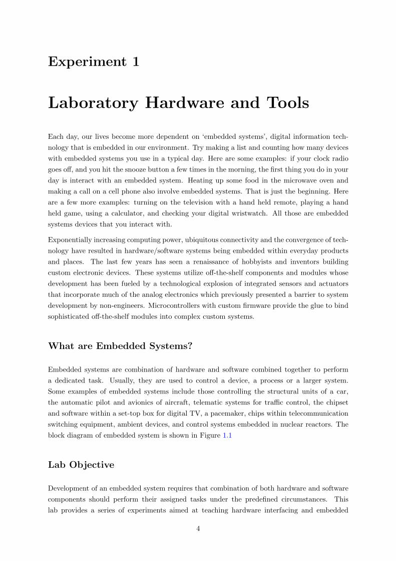
Expansion Board
The headers on the Launchpad can be used to connect the external peripherals and electronic
devices to develop a custom application. Like other expansion boards, we designed our own
expansion board for Stellaris Launchpad to explore different applications that our MCU can
support. This board helps students get familiar with different peripherals of MCU by interacting
with simple electronic components like seven segment display, 16x2 character LCD, temperature
sensor (LM35), analog potentiometer, MAX232 and DB9 connector for interfacing UART using
7
(a) UET Launchpad expansion board (b) Launchpad mounted on expansion board
Figure 1.3: UET Launchpad Expansion board
level shifter, real time clock (DS1307) for I2C interfacing. Figure 1.3 shows the expansion board
with and without launchpad mounted on it
Stellaris LM4F Series Overview
The LM4F120 microcontrollers are based on the ARM Cortex-M4 core. The Cortex-M4 differs
from previous generations of ARM processors by defining a number of key peripherals as part of
the core architecture including interrupt controller, system timer and, debug and trace hardware
(including external interfaces). This additional level of integration means that system software
such as real-time operating systems and hardware development tools such as debugger interfaces
can be common across the family of processors.
The LM4F microcontroller provides a wide range of connectivity features such as CAN, USB
Device, SPI/SSI, I2C, UARTs. It supports high performance analog integration by providing
two 1MSPS 12-bit ADCs and analog and digital comparators. It has best-in-class power con-
sumption with currents as low as 370µA/MHz, 500µs wakeup from low-power modes and RTC
currents as low as 1.7µA. This Stellaris series offers a solid road map with higher speeds, larger
memory and ultra low currents.

8 CHAPTER 1. LABORATORY HARDWARE AND TOOLS
Table 1-2. Stellaris LM4F120H5QR Microcontroller Features
DescriptionFeature
ARM Cortex-M4F processor coreCore
80-MHz operation; 100 DMIPS performancePerformance
256 KB single-cycle Flash memoryFlash
32 KB single-cycle SRAMSystem SRAM
2KB of EEPROMEEPROM
Internal ROM loaded with StellarisWare® softwareInternal ROM
Communication Interfaces
Eight UARTsUniversal Asynchronous Receivers/Transmitter (UART)
Four SSI modulesSynchronous Serial Interface (SSI)
Four I2C modules with four transmission speeds including high-speedmode
Inter-Integrated Circuit (I2C)
CAN 2.0 A/B controllersController Area Network (CAN)
USB 2.0 DeviceUniversal Serial Bus (USB)
System Integration
ARM® PrimeCell® 32-channel configurable μDMA controllerMicro Direct Memory Access (µDMA)
Six 16/32-bit GPTM blocks and six 32/64-bit Wide GPTM blocksGeneral-Purpose Timer (GPTM)
Two watchdog timersWatchdog Timer (WDT)
Low-power battery-backed Hibernation moduleHibernation Module (HIB)
Six physical GPIO blocksGeneral-Purpose Input/Output (GPIO)
Analog Support
Two 12-bit ADC modules with a maximum sample rate of one millionsamples/second
Analog-to-Digital Converter (ADC)
Two independent integrated analog comparatorsAnalog Comparator Controller
16 digital comparatorsDigital Comparator
One JTAG module with integrated ARM SWDJTAG and Serial Wire Debug (SWD)
64-pin LQFPPackage
Industrial (-40°C to 85°C) temperature rangeOperating Range
Figure 1-2 on page 47 shows the features on the Stellaris LM4F120H5QR microcontroller. Notethat there are two on-chip buses that connect the core to the peripherals. The Advanced PeripheralBus (APB) bus is the legacy bus. The Advanced High-Performance Bus (AHB) bus provides betterback-to-back access performance than the APB bus.
January 19, 201346Texas Instruments-Advance Information
Architectural Overview
Figure 1.4: Stellaris LM4F120H5QR Microcontroller Features
LM4F120H5QR Microcontroller Overview
The Stellaris LM4F120H5QR microcontroller combines complex integration and high perfor-
mance with the features shown in Figure 1.4.
The Cortex-M4 core architecture consists of a 32-bit processor with a small set of key periph-
erals. The Cortex-M4 core has a Harvard architecture meaning that it uses separate interfaces
to fetch instructions and data. This helps ensure the processor is not memory starved as it
permits accessing data and instruction memories simultaneously. From the perspective of the
CM4, everything looks like memory it only differentiates between instruction fetches and data
accesses. The interface between the Cortex-M4 and manufacturer specific hardware is through
three memory buses ICode, DCode, and System which are defined to access different regions
of memory.
The block diagram of Stellaris Launchpad evaluation board in Figure 1.5 gives an overview of
how the Stellaris ICDI and other peripherals are interfaced with microcontroller.

9
Stellaris ICDIJTAG/SWD
UART0
VDD
USB Debug Connector
Power SelectSwitch
Power Management
GPIO
ICD
I
XTAL
RESETRESETSWITCH
OSC0
OSC1
LM4F120H5QR
Figure 1.5: Block Diagram of Stellaris Launchpad Board
Stellaris Development Tools
Getting Started With the Stellaris EK-LM4F120XL LaunchPad Workshop - Code Composer Studio 2 - 3
Stellaris Development Tools
Development Tools for Stellaris MCUs
Eval Kit License
30-day full function.
Upgradeable
32KB code size limited.
Upgradeable
32KB code size limited.
Upgradeable
Full function. Onboard
emulation limited
Compiler GNU C/C++ IAR C/C++ RealView C/C++ TI C/C++
Debugger / IDE gdb / Eclipse
C-SPY / Embedded Workbench
µVision CCS/Eclipse-based suite
What is CCS?...
Figure 1.6: Stellaris Development Tools
Stellaris Development Tools
To develop an application and run it on Stellaris Launchpad, a software is required to write
our code, debug it and download it to the device. Fortunately, many IDEs are available for
the application development of Stellaris Launchpad. Figure 1.6 shows different IDEs available
for Stellaris development. In this lab, we will use Sourcery Codebench as our development
tool.

10 CHAPTER 1. LABORATORY HARDWARE AND TOOLS
Setup Keil µVision to Write Code
1. Run the software by clicking the icon on desktop, if available, or by clicking on Start →All Programs →Keil µVision. An interface similar to one shown in Figure 1.7 will
open.
Figure 1.7: Keil interface on start
2. Click on Project tab and choose New µVision Project from the drop-down list as shown
in Figure 1.8
Figure 1.8: Create new µVision project

11
3. Select and create a directory, then assign a name to your project (project name can
be different from folder name) then click on Save. Do not make a directory, file
or project name with a space in it. A space will prevent simulation from working
properly.
Figure 1.9: Type the name of the project in Keil and save it
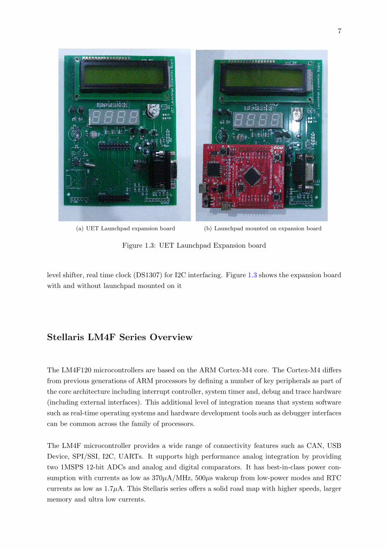
4. To select a microcontroller double click on Texas Instruments and select TM4C1233H6PM.
Click OK.(See Figure 1.10 and 1.11)
Figure 1.10: Select the manufacturer of your microcontroller
12 CHAPTER 1. LABORATORY HARDWARE AND TOOLS
Figure 1.11: Select the part number for your microcontroller
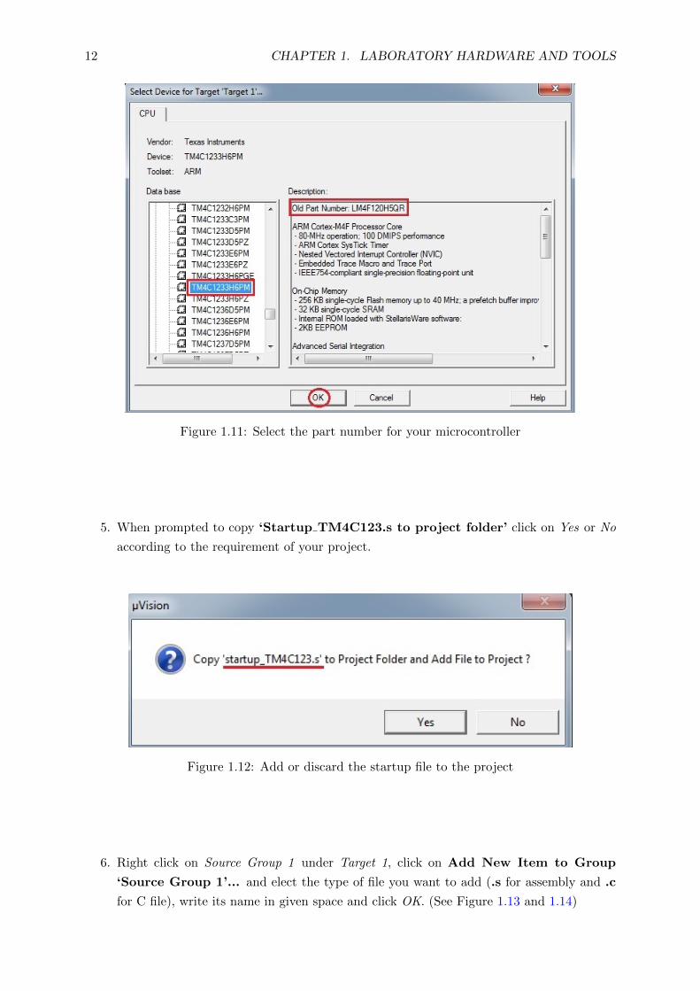
5. When prompted to copy ‘Startup TM4C123.s to project folder’ click on Yes or No
according to the requirement of your project.
Figure 1.12: Add or discard the startup file to the project
6. Right click on Source Group 1 under Target 1, click on Add New Item to Group
‘Source Group 1’... and elect the type of file you want to add (.s for assembly and .c
for C file), write its name in given space and click OK. (See Figure 1.13 and 1.14)

13
Figure 1.13: Add new file to the project
Figure 1.14: Select file type and save the new file
7. Double click on the file name under Source Group 1 in Project window to open it in the
editor pane. Here, you can write and edit the code.

14 CHAPTER 1. LABORATORY HARDWARE AND TOOLS
Figure 1.15: Edit the file in the text editor window
8. Next step after writing the code is to build your code. As shown in Figure 1.16 click
on Project menu and select Build Target from the drop down list. You can also build
your project by clicking Build button in Build bar. Build Output window at displays the
errors, warning and build messages during build process. Double-click a message to open
the corresponding source file. Build button translates modified or new source files and
generates the executable file. The Rebuild command translates all source files regardless of
modifications. Simulation highlighted at the bottom signifies that we are not downloading
our code on hardware.
Figure 1.16: Build the project
9. After successsfully building the code, you can run the program through the Debug menu.
As shown in Figure 1.17 select the Start/Stop Debug Session option from the debug menu

15
or press the debug button. Click on “OK” for the pop up window showing “EVALUATION
MODE, Running with Code Size Limit: 32K”.
Figure 1.17: Build the project
10. Open your uVision to full screen to have a better and complete view. In Figure 1.18
the left hand side window shows you the registers and the right side window shows the
program code. There are some other windows open. You may adjust the size of them to
see better. Run the program step by step as shown in, you can observe the change of the
values in the registers. Click on the Start/Stop Debug Session again to stop executing the
program.
Figure 1.18: Debug window in Keil