Embed Size (px)
Citation preview
1
Ruediger Heim, Ivo KrauseFraunhofer Institute for Structural Durability and System Reliability LBF
ABSTRACT
Automotive engineering is continously moving toward the integration of different processes for accelerating ve-hicle development. Since the products become more and more a system, the methods to assist this transformation process become even more complicated.
Experimental proof is an essential measure for reliability, robustness and quality. Since many vehicle components are relevant for operational safety, these parts must not fail causing an accident. This has to be ensured by experi-mental methods such as rig based durability tests. Hence, service load simulation & evaluation becomes an instru-ment to actively guide the product development process, rather than to release newly developed parts only. If both, loading as well as assembly interaction are incorporated in a realistic manner, cost and time are saved due to the elimination of specialized on-track measurements.
Hence, lab based fatigue evaluation is presented as an in-tegrated part of the overall vehicle development process. For wheel & hub assemblies as well as complete axle sys-tems, the LBF durability test procedures are introduced, covering rotating and load transfer components.
INTRODUCTIONVehicle development becomes accelerated by the inte-gration of different methods and processes to further shorten the design creation time in all stages. This is done within a time frame, which is 18 to 24 months today – from verified data release up to the start of production (SOP). Hence, vehicle development is by far more than the ve-hicle-level refinement from early stage “mule” testing to the production-ready car. The overall process relies on its ability to collaborate on lab, track and analytical tests to concurrently design, develop and validate the vehicle as an integrated set of subsystems, such as body, chassis or powertrain.
Traditionally, vehicle development was performed by design, prototype build & test and re-design sequenti-ally, that was carried out on expensive full vehicle level. A couple of years ago, this was changed toward a target setting & cascading process, including synthesis and con-firmation stages. Benefitially, this enables the OEM to get the tier-1 suppliers integrated into this process as well. To keep it manageable, the overall requirement is to main-
tain communication and to bring math and hardware peo-ple together. Starting with the target setting process, the vehicle development can be performed properly to achie-ve balanced properties in all areas (fig. 1.).
Fig. 1. – Graphical representation of (un)balanced vehicle properties
While target setting as well as cascading the design re-quirements are analytical processes solely, design synthe-sis and optimization are supported by physical testing. This is essential for verification and alignment, captur-ing effects, that cannot be covered by math models suf-ficiently. These are e.g. wear, corrosion, joint fatigue or residual stresses, which are component and/or assembly properties, that become introduced by manufacturing, assembly or operational use.
THE VALUE OF EARLY STAGE RIG TESTING
BASIC VEHICLE DEVELOPMENT PROCESSSince the integrated design & development process starts with a break-down from corporate product requirements to component targets, this phase is dominated by the use of math models & methods. On the component level, the design iteration and optimization is performed by apply-ing component-specific loads and constraints. The design synthesis starts with a collection of components, which build an assembly group or a sub-system. This is the first step bringing individual parts, their relationship and as-sembly tolerances together. Hence the top level systems are gradually built by component and sub-system synthe-sis (fig. 2.).
This stepwise process enables the car manufacturer to virtually simulate & optimize as well as to track time and costs efficiently. Concurrently to these activities, con-firmation testing may start as prototype parts become available. The type of tests will change as the product’s design becomes mature and the product moves from conceptual to final design.
LABORATORY BASED DURABILITY TESTING – METHODS AND BACKGROUND

2
Fig. 2. – “V-shaped” basic development process
Early stage testing is benefitial for vehicle attributes, which can be evaluated on sub-system level, such as du-rability and fatigue life. While NVH and crash-worthiness have to be tested and fine tuned strictly on vehicle le-vel, structural durability requirements can be targetted beyond component level. Performing assembly and sub-structure durability tests lead to an early vehicle attribute confirmation without running full vehicle tests. Hence, the cost expensive confirmation prototypes can be used for evaluating other attributes or simply be eliminated. Even the product validation and quality testing phase can be shortened, if the pre-tested groups still represent the design content accordingly. This is possible because the design loads can be evaluated deterministically to a cer-tain content, and even the transient dynamic characteris-tic of road load data can be handled by statistics properly. This enables the car manufacturer to start with the dura-bility tests without having dedicated road load data.
Since platform commonality is a major strategy to gene-rate customized derivatives by a limited number of basic structures, the sub-system durability testing can be ap-plied to the shared design content benefitially: The plat-form components can be evaluated separately from the derivatives to some content.
As an essential input for defining the early stage test pro-cedures, boundary conditions as well as test & validation loads have to be generated. Since vehicle suspension systems are relatively well defined in terms of input load mechanism and load transfer characteristics, the suspen-sion durability can be tested independently from chassis,
powertrain or vehicle body (fig. 3.).
Fig. 3. – Suspension system & wheel end
This ensures some flexibility in terms of vehicle develop-ment timing as well as there is the opportunity to statisti-cally evaluate the durability behaviour of safety relevant components such as wheels, hubs or suspension struts and links.
PRODUCT RELIABILITYWhile product reliability is usually defined as the ability to perform the intended mission without failing, the requi-rement for safety relevant parts is, that they must not fail – even in the case of special events, which induce loads beyond normal operational profile. Hence, besides from normal service loads, rare occurences have to be taken into account, such as curbstone or obstacle crossing. The-se manoeuvres shall not reduce the durable life of the components, which means, that the design limit has to be extended to the structural yield point (fig. 4.).
Fig. 4. – Special event loading by obstacle crossing
Beyond structural yielding, the damage content of a sin-gle event becomes so severe, that the durable life will be reduced subsequently. These misuse loads are not part of the structural durability testing, but have to be applied without resulting in brittle fracture.

3
Dealing with reliability – especially for safety relevant parts and assemblies – necessarily has to cope with an universally agreed definition of product failure. This may seem a bit curios, but identical tests performed on the same product may generate an evaluation, that is com-pletely different simply because people have their own definition of product failure. Since complex products can have a large number of distinct failure modes, a certain degree of flexibility is called for in the failure definition: Hence, it may be benefitial to have a multi-tiered failure evaluation process, which takes into account time and se-verity.
• Type I – Failure causing severe operational incidents, which are definitely not allowed for safety relevant parts• Cracks in the wheel disc area, endangering the struc-tural integrity of the wheel • Type II – Intervention as an unplanned occurrence, that requires the user to interact on maintenance level• Loss of wheel bolt tension force, which potentially causes serious wheel stud failures and therefore gener-ates a type I issue subsequently• Type III – Event, which is not failure related, but of engineering interest due to its frequency of occurence
Actually a type I issue must not occur for safety relevant components throughout the complete lifetime. While this lifetime is limited to e.g. 175,000 miles (300,000 km) for passenger cars, vans and small trucks, the structural inte-grity has to be kept all time. Since small initial cracks can-not be avoided at the end-of-life level entirely, the crack propagation characteristics have to be examined careful-ly as well. This is performed by enlarged tests, which co-ver the duration beyond the formal requirements.By means of 3 samples the performance of the basic population is evaluated for rotating suspension compo-nents, using appropriate safety and risk factors based on the assumption of Gaussian distribution for load and strength characteristics (fig. 5.).
Fig. 5. – Definition of safety factor by means of statistics
When looking at wheel and suspension components, one major difference is their kinematics: While the wheel end is forced by the rotational degree of freedom, the sus-pension is acting in translational direction primarily. For early stage testing these different load mechanism lead to different test procedures, and consequently to differ-ent test rig setup. By using appropriate load & boundary conditions, wheel and suspension systems can be tested in a service-like mode.
DURABILITY EVALUATION FOR WHEELS & HUBSFor rotating components, such as wheel, hub and bearing, the test procedure has to be designed according to the complex kinematics and load transfer path. Hence, simpli-fied procedures – like the rotating bending test for wheels – can be applied for assessment or comparison tests, but not for product validation and qualification. Since product validation has to ensure, that all of the design goals have been met, the test mode has to cope with service-like loa-ding and assembly interaction. For the complete wheel end the operational mode can be simulated by using a bia-xial test machine: Therefore, the assembly of the rotating components is completed by a tire, which acts as the load transfer element rolling inside a drum (fig. 6.).
Fig. 6. – Setup of Biaxial Wheel & Hub Test Rig (LBF patent)
Biaxial actuators forcing vertical as well as lateral loads inside the system, which are representing operational forces realistically. Hence, different load sequences are necessary, which partially act as pure vertical loading, while other sequences contain a superposition of vertical and lateral forces.
This procedure was developed 25 years ago at Fraunhofer LBF, and it became a standard for many European OEM and suppliers as well as it is introduced as an SAE recom-mended practise. Major lab test manufacturer such as

4
MTS Systems Corporation or Fraunhofer LBF itself have been built more than 40 Biaxial Wheel & Hub Test Ben-ches (ZWARP) world wide. The drum diameter is realized in three different sizes; hence test benches for using tires from 12” up to >22.5” are applicable (fig 7.).
Since the test mode is kinematically reversed compared to the road operation, the load mechanism is generally quasi-static. But, this is used to stress all structural are-as circumferentially, not to peak load certain areas ran-domly: The time duration of the individual load sequences have to be adjusted to cover at least one wheel revoluti-on. From practical point of view, the load vs. time history is generated by compiling the stochastic nature of road transport utilization into load block sequences.
Fig. 7. – Running the Biaxial Wheel & Hub Test Rig (ZWARP)
Therefore, it is necessary to analyze the life-cycle and usa-ge loading content carefully. With regard to the usage loa-ding for rotating components, the major manoeuvres are straight driving and cornering operations, while brake as well as acceleration torque do not induce severe dama-ge for traditional wheel or hub design directly. Actually torque loading has to be considered for effects on the wheel bolts, but this is beyond the content of this paper.
LOAD FILE DEVELOPMENTThe statistical examination of road & on-track measure-ments show, that straight driving is the predominate part of the usage spectra, while cornering is about 4% of the total vehicle mileage only. For cornering operation, there is a strong correlation between vertical and lateral forces acting on the tire footprint. Hence, the test load sequen-ces representing cornering operations can be derived from vehicle dynamics relatively easily.Different to this, at rough road driving the lateral forces are not correlated to the superimposed vertical loading. Hence, the test load spectra has to use representative load sequences applying inboard as well as outboard forces, which become added to the vertical loads. In this
way, a generic load spectra can be developed, which is statistically adequate to the usage spectra, if peak loading as well as shape and content of the cumulative load cyc-le distribution are represented accurately. By means of analytical damage calculation, the test spectra is derived from this generic load spectra. Since overstress accelera-tion of the test spectra could cause severe impact on the damage mechanism by generating stresses beyond the structural yield limit, the more appropriate strategy is to apply usage rate acceleration: Therefore, the shape and content of the cumulative distribution are modified to re-duce the time duration needed for the durability evalua-tion process. The test spectra represents a compressed load program in terms of number of load cycles, while keeping the damage content of the generic load spectra. The continuous test spectra is then practically applied as a sequence of different load blocks, which are stochasti-cally ordered (fig. 8.).
Fig. 8. – Vehicle design and test spectra
For the Biaxial Wheel & Hub Test Rig different load files have been developed, which represent the damage con-tent of various usage spectra globally. Since most Euro-pean vehicle manufacturer used to use Germany’s famous 13.6-mile Nurburgring race track, offering unique combi-nations of curves, bumps and velocity changes, Fraun-hofer LBF developed its Eurocycle load file by processing some signal content from these on-track measurements (fig. 9.).
Fig. 9. – Load sequences from LBF Eurocycle load file
Hence, LBF’s Eurocycle is a generic load program covering 17.75 miles (30 km) for passenger cars and 38.5 miles (65 km) for commercial trucks per lap, including a dedicated portion from the Nurburgring. These individual laps are repeated according to the content of the full test spectra,
5
which is between 4,730 miles (8,000 km) for passenger cars and 11,830 miles (20,000 km) for truck applications. By applying an average speed of 50 to 59 mph (85 to 100 kph) in the test bench, the total test time is shortened to about 4 to 10 days for each sample instead of performing time & cost intensive on-track durability tests.
Since the LBF Eurocycle load program is covering almost all different usage spectra for road transport of European customers, it can be used without dedicated road load data acquisition, simply by adjusting load parameters ac-cording to the rated wheel load and the specific vehicle type. A generic load file related to passenger cars and small truck applications in North America has been re-cently developed by the SAE. The capability of the Biaxial Wheel & Hub Test Rig to reproduce virtually any combi-nation of vertical and lateral loads has been successfully used to develop pretty specialized load files for the acce-lerated test of rotating components for e.g. farm machi-nes as well.
Because the individual components such as wheel, hub and bearing are assembled as they will be in the vehicle, the assembly interaction and properties are covered rea-listically. This is increasingly important as the wheel end system becomes more complex by feature integration as well as design and weight optimization.
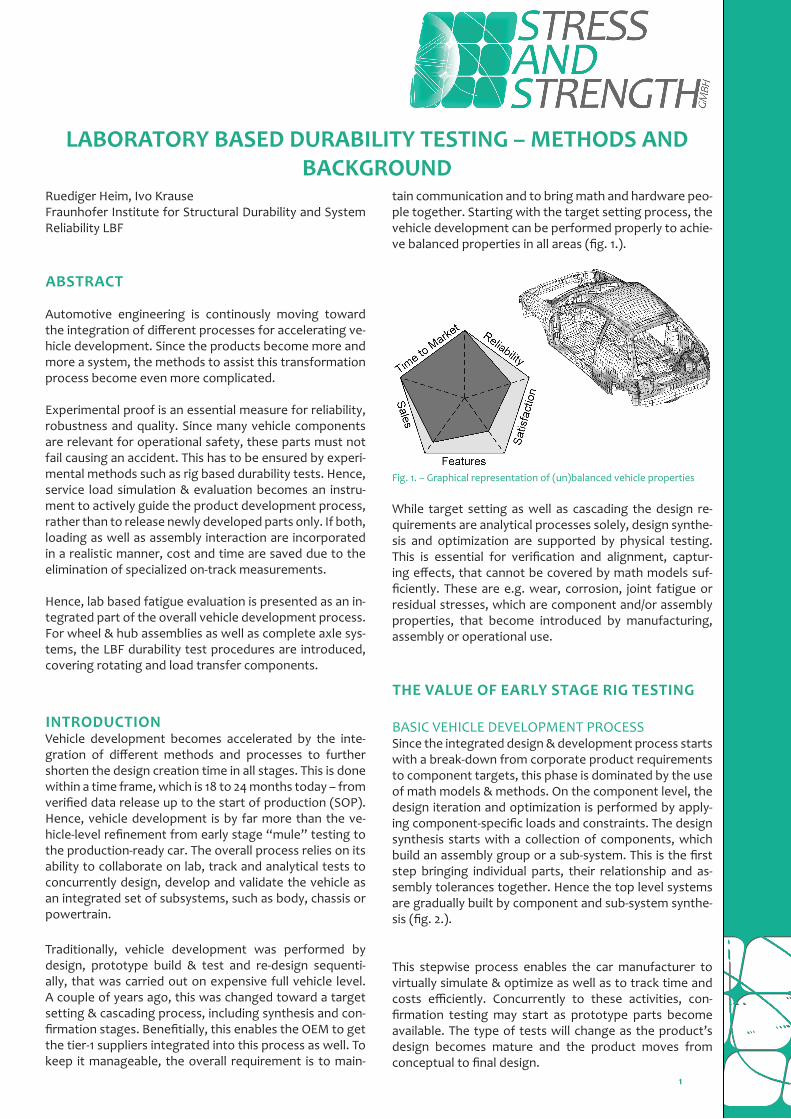
Practical applications show the unique quality of test re-sults, which are pretty close to operational failures. Since the complex load mechanism of the complete wheel end is reproduced accurately, the critical areas in terms of fa-tigue failure are fully detected (fig. 10.).
Fig. 10. – Crack at vent hole section examined by ZWARP testing
After vehicle load data is available, the load file for biaxial wheel testing can be iterated according to the informati-on update. This helps to generate and control the range
of applicable test parameters as well.Using reliability targets as well as probability data coming from the usage spectra and product failures, the number of samples to be tested as well as the test duration can be evaluated. Since the fatigue failure rate of structural components can be described by Gaussian distribution quite well, the mathematical background of a reliability engineering program for wheels and hubs is pretty much straight forward. Converting the Gaussian distribution to the more general Weibull mathematics means, that the Weibull shape parameter b is in the range of 3.2 to 3.6. Then the parameter set to cope with a statistically suffici-ent overall test content can be derived accordingly. Since rolling contact fatigue is based on a different damage be-haviour, for the evaluation of the bearing performance in the Biaxial Test Facility (ZWARP) the test duration is diffe-rent. This can be simply matched by using a Weibull shape parameter b equal to 1.5 to 2.0 approximately.
MATH MODELINGActually, this – in terms of loading and boundary condi-tions well defined process can be successfully approached for math modeling as well. While the interfaces between the individual components are described geometrically, the load input by the tire is transformed to math based distributed forces, which are identified by experimental strain analyses. Therefore, the strain-gauge signal vs. wheel revolution is monitored for relevant areas of the complete assembly.
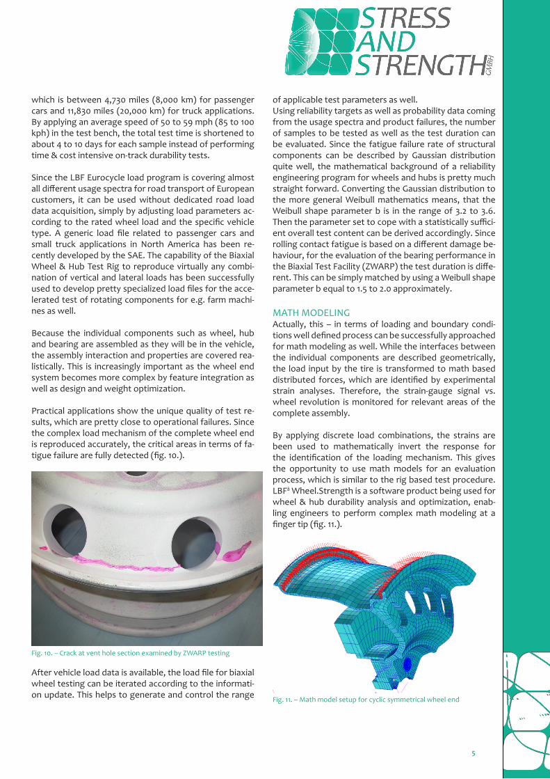
By applying discrete load combinations, the strains are been used to mathematically invert the response for the identification of the loading mechanism. This gives the opportunity to use math models for an evaluation process, which is similar to the rig based test procedure. LBFâ Wheel.Strength is a software product being used for wheel & hub durability analysis and optimization, enab-ling engineers to perform complex math modeling at a finger tip (fig. 11.).
Fig. 11. – Math model setup for cyclic symmetrical wheel end
6
The system specific solution actually is the definition of the loading to the wheel, which is equivalent to that based on the tire characteristics, as well as the durability post-processor to compute the required fatigue strength (RFS). This is a scalar value calculated for each node of the math model to evaluate the minimum fatigue strength lo-cally needed.
SUSPENSION DURABILITY EVALUATIONThe process of developing physical load cases for the re-presentation of the total usage spectra can be adapted to suspension testing as well. Therefore, at least braking has to be added to vehicle straight driving and cornering. Few vehicle specific operations, such as small radius trai-ler turning or off-road conditions have to be applied if necessary. Again, the total usage spectra is been repre-sented by overlaying the cumulative load cycles of the in-dividual manoeuvres. While the shape and the content of these individual spectra can be evaluated relatively well, the peak loading – and therefore the start point of the cu-mulative distribution – is hardly to be assessed accurately, especially for dedicated manoeuvres such as off-road use or small radius trailer turning. But, comparative measure-ments or predecessor load data can be used to extrapola-te on the peaks as well as using math models, which have to cover the major vehicle parameters.
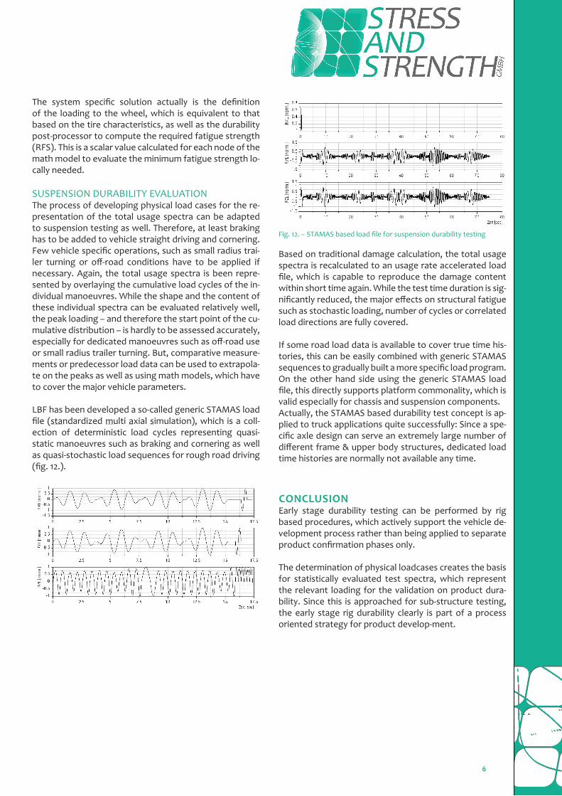
LBF has been developed a so-called generic STAMAS load file (standardized multi axial simulation), which is a coll-ection of deterministic load cycles representing quasi-static manoeuvres such as braking and cornering as well as quasi-stochastic load sequences for rough road driving (fig. 12.).
Fig. 12. – STAMAS based load file for suspension durability testing
Based on traditional damage calculation, the total usage spectra is recalculated to an usage rate accelerated load file, which is capable to reproduce the damage content within short time again. While the test time duration is sig-nificantly reduced, the major effects on structural fatigue such as stochastic loading, number of cycles or correlated load directions are fully covered.
If some road load data is available to cover true time his-tories, this can be easily combined with generic STAMAS sequences to gradually built a more specific load program. On the other hand side using the generic STAMAS load file, this directly supports platform commonality, which is valid especially for chassis and suspension components. Actually, the STAMAS based durability test concept is ap-plied to truck applications quite successfully: Since a spe-cific axle design can serve an extremely large number of different frame & upper body structures, dedicated load time histories are normally not available any time.
CONCLUSIONEarly stage durability testing can be performed by rig based procedures, which actively support the vehicle de-velopment process rather than being applied to separate product confirmation phases only.
The determination of physical loadcases creates the basis for statistically evaluated test spectra, which represent the relevant loading for the validation on product dura-bility. Since this is approached for sub-structure testing, the early stage rig durability clearly is part of a process oriented strategy for product develop-ment.

7
CONTACTMain author: Ruediger Heim
Fraunhofer Institute for Structural Durability and System Reliability – LBF
Head of Competence Centre
Service Load Simulation and Evaluation
Bartningstr. 47; D-64289 Darmstadt, Germany
E-Mail: [email protected]